Product datasheet - Sky-brokers.com
Product datasheet - Sky-brokers.com
Product datasheet - Sky-brokers.com

Create successful ePaper yourself
Turn your PDF publications into a flip-book with our unique Google optimized e-Paper software.
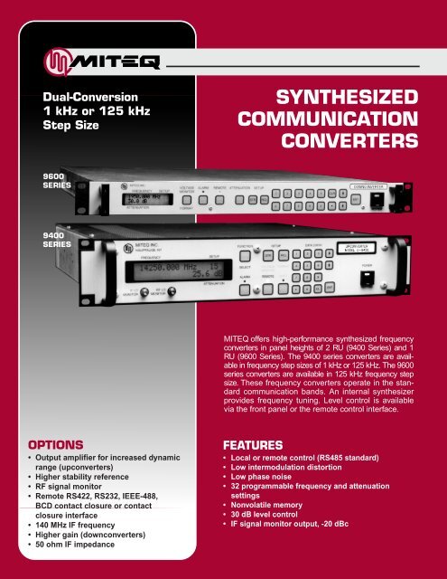
Dual-Conversion<br />
1 kHz or 125 kHz<br />
Step Size<br />
SYNTHESIZED<br />
COMMUNICATION<br />
CONVERTERS<br />
9600<br />
SERIES<br />
9400<br />
SERIES<br />
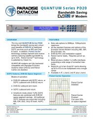
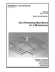
MITEQ offers high-performance synthesized frequency<br />
converters in panel heights of 2 RU (9400 Series) and 1<br />
RU (9600 Series). The 9400 series converters are available<br />
in frequency step sizes of 1 kHz or 125 kHz. The 9600<br />
series converters are available in 125 kHz frequency step<br />
size. These frequency converters operate in the standard<br />
<strong>com</strong>munication bands. An internal synthesizer<br />
provides frequency tuning. Level control is available<br />
via the front panel or the remote control interface.<br />
OPTIONS<br />
• Output amplifier for increased dynamic<br />
range (upconverters)<br />
• Higher stability reference<br />
• RF signal monitor<br />
• Remote RS422, RS232, IEEE-488,<br />
BCD contact closure or contact<br />
closure interface<br />
• 140 MHz IF frequency<br />
• Higher gain (downconverters)<br />
• 50 ohm IF impedance<br />
FEATURES<br />
• Local or remote control (RS485 standard)<br />
• Low intermodulation distortion<br />
• Low phase noise<br />
• 32 programmable frequency and attenuation<br />
settings<br />
• Nonvolatile memory<br />
• 30 dB level control<br />
• IF signal monitor output, -20 dBc
SPECIFICATIONS<br />
UPCONVERTER<br />
DOWNCONVERTER<br />
Type Dual conversion Dual conversion<br />
Tunability Second local oscillator only First local oscillator only<br />
Frequency sense No inversion No inversion<br />
Input characteristics<br />
Frequency 70 ±20 MHz (140 ±40 MHz optional) Refer to model numbers and tables<br />
Impedance 75 ohms (50 ohms optional) 50 ohms<br />
Return loss 26 dB minimum 20 dB minimum<br />
Signal monitor -20 dBc nominal Option 2A<br />
LO leakage N/A -80 dBm maximum<br />
Output characteristics<br />
Frequency Refer to model numbers and tables 70 ±20 MHz (140 ±40 MHz optional)<br />
Impedance 50 ohms 75 ohms (50 ohms optional)<br />
Return loss 20 dB minimum 26 dB minimum<br />
Power output -5 dBm nominal (up to +20 dBm with +15 dBm typical, +10 dBm minimum<br />
(1 dB <strong>com</strong>pression) optional output amplifiers, refer to options)<br />
Signal monitor Option 2A -20 dBc nominal<br />
Transfer characteristics<br />
Noise figure 20 dB typical, 25 dB maximum 10 dB typical, 12 dB maximum,<br />
*12 dB typical, 15 dB maximum<br />
Gain 11 dB nominal (at minimum attenuation) 30 dB nominal (higher gain optional)<br />
Image rejection 80 dB minimum 80 dB minimum<br />
Level stability ±0.25 dB/day maximum at constant temp. ±0.25 dB/day maximum at constant temp.<br />
Amplitude response ±0.25 dB/±20 MHz, ±0.20 dB/±18 MHz ±0.25 dB/±20 MHz, ±0.20 dB/±18 MHz<br />
Group delay (±18 MHz) 0.03 ns/MHz maximum linear, 0.03 ns/MHz maximum linear,<br />
0.01 ns/MHz 2 maximum parabolic, 0.01 ns/MHz 2 maximum parabolic,<br />
1 ns peak-to-peak maximum ripple 1 ns peak-to-peak maximum ripple<br />
Intermodulation distortion With two -20 dBm output signals, With two -10 dBm output signals,<br />
(third order) 50 dBc minimum 60 dBc minimum<br />
AM/PM conversion 0.1°/dB maximum to -15 dBm output 0.1°/dB maximum to +5 dBm output<br />
Gain slope 0.02 dB/MHz maximum 0.02 dB/MHz maximum<br />
Spurious outputs<br />
For converters with RF frequencies below 8.5 GHz<br />
Signal related 65 dBc minimum 65 dBc minimum<br />
Signal independent -90 dBm maximum -90 dBm maximum<br />
-80 dBm maximum (Option 11A) -75 dBm maximum (Option 16A)<br />
-70 dBm maximum (Option 11B) -65 dBm maximum (Option 16C)<br />
For converters with RF frequencies above 8.5 GHz<br />
Signal related 60 dBc minimum 60 dBc minimum<br />
Signal independent -90 dBm maximum -90 dBm maximum<br />
-80 dBm maximum (Option 11A) -75 dBm maximum (Option 16A)<br />
-75 dBm maximum (Option 11B) -65 dBm maximum (Option 16C)<br />
Gain adjustment 30 dB, local and remote control 30 dB, local and remote control<br />
Gain adjustment step size 0.2 dB 0.2 dB<br />
Frequency stability ±2 x 10 -8 , 0 to 50°C ±2 x 10 -8 , 0 to 50°C<br />
(higher stability options available),<br />
(higher stability options available),<br />
±5 x 10 -9 /day typical ±5 x 10 -9 /day typicial<br />
(fixed temp. after 24 hour on time)<br />
(fixed temp. after 24 hour on time)<br />
Upconverter mute 60 dB N/A<br />
Phase noise See table for curve and graph designations See table for curve and graph designations
DOWNCONVERTERS<br />
2 RU (3.5 INCHES) DOWNCONVERTERS – 9400 SERIES<br />
Input Frequency 125 kHz Step Size 1 kHz Step Size Phase Noise<br />
(GHz) Model Number Model Number Characteristics<br />
0.95 – 1.45 D-9400-1 D-9400-1-1K Curve 3<br />
0.95 – 1.75 D-9400-3 D-9400-3-1K Curve 3<br />
0.95 – 2.05 D-9400-5 D-9400-5-1K Curve 3<br />
1.5 – 1.8 D-9400-2 D-9400-2-1K Curve 1<br />
1.7 – 2.4 D-9400-4 D-9400-4-1K Curve 3<br />
2.2 – 2.3 D-9400 D-9400-1K Curve 1<br />
3.0 – 4.2 D-9401-2 D-9401-2-1K Curve 2<br />
3.4 – 4.2 D-9401-1 D-9401-1-1K Curve 2<br />
3.62 – 4.205 D-9402 D-9402-1K Curve 1<br />
4.5 – 4.8 D-9402-2 D-9402-2-1K Curve 1<br />
5.845 – 6.430 D-9404 D-9404-1K Curve 1<br />
6.4 – 7.2 D-9405-1 D-9405-1-1K Curve 2<br />
7.25 – 7.75 D-9405 D-9405-1K Curve 2<br />
7.9 – 8.4 D-9406 D-9406-1K Curve 2<br />
8.0 – 8.5 D-9407 D-9407-1K Curve 2<br />
10.7 – 11.7 D-9408-2 D-9408-2-1K Curve 2<br />
10.7 – 12.0 D-9408-5 D-9408-5-1K Curve 3<br />
10.7 – 12.75 D-9408-6* D-9408-6-1K* Curve 3<br />
10.95 – 11.7 D-9408 D-9408-1K Curve 3<br />
10.95 – 12.2 D-9408-1 D-9408-1-1K Curve 4<br />
10.95 – 12.75 D-9408-3* D-9408-3-1K* Curve 4<br />
11.45 – 12.75 D-9409-3 D-9409-3-1K Curve 4<br />
11.46 – 11.96 D-9409-2 D-9409-2-1K Curve 3<br />
11.7 – 12.2 D-9409 D-9409-1K Curve 3<br />
11.7 – 12.75 D-9409-1 D-9409-1-1K Curve 3<br />
12.2 – 12.75 D-9410 D-9410-1K Curve 3<br />
13.75 – 14.5 D-9411-1 D-9411-1-1K Curve 3<br />
14.0 – 14.5 D-9411 D-9411-1K Curve 3<br />
17.3 – 17.8 D-9412 D-9412-1K Curve 4<br />
17.3 – 18.1 D-9412-1 D-9412-1-1K Curve 4<br />
17.3 – 18.4 D-9412-2 D-9412-2-1K Curve 4<br />
1 RU (1.75 INCHES) DOWNCONVERTERS – 9600 SERIES<br />
Input Frequency 125 kHz Step Size Phase Noise<br />
(GHz) Model Number Characteristics<br />
0.95 – 1.45 D-9600-1 Curve 3<br />
0.95 – 1.75 D-9600-3 Curve 3<br />
1.5 – 1.8 D-9600-2 Curve 1<br />
2.2 – 2.3 D-9600 Curve 1<br />
3.4 – 4.2 D-9601-1 Curve 2<br />
3.62 – 4.205 D-9602 Curve 1<br />
4.5 – 4.8 D-9602-2 Curve 1<br />
6.4 – 7.2 D-9605-1 Curve 2<br />
7.25 – 7.75 D-9605 Curve 2<br />
10.95 – 11.7 D-9608 Curve 3<br />
10.95 – 12.75 D-9608-3* Curve 4<br />
11.7 – 12.2 D-9609 Curve 3<br />
12.2 – 12.75 D-9610 Curve 3<br />
* References noise figure under “Downconverter Specifications” section
UPCONVERTERS<br />
2 RU (3.5 INCHES) UPCONVERTERS – 9400 SERIES<br />
Output Frequency 125 kHz Step Size 1 kHz Step Size Phase Noise<br />
(GHz) Model Number Model Number Characteristics<br />
0.95 – 1.45 U-9448 U-9448-1K Curve 3<br />
0.95 – 1.75 U-9448-1 U-9448-1-1K Curve 3<br />
0.95 – 2.05 U-9448-3 U-9448-3-1K Curve 3<br />
1.5 – 1.8 U-9448-2 U-9448-2-1K Curve 1<br />
3.4 – 4.2 U-9451-1 U-9451-1-1K Curve 2<br />
3.62 – 4.205 U-9451 U-9451-1K Curve 1<br />
5.725 – 6.725 U-9453-6 U-9453-6-1K Curve 2<br />
5.845 – 6.430 U-9453 U-9453-1K Curve 1<br />
5.85 – 6.485 U-9453-3 U-9453-3-1K Curve 1<br />
5.85 – 6.665 U-9453-1 U-9453-1-1K Curve 2<br />
5.85 – 6.725 U-9453-5 U-9453-5-1K Curve 2<br />
5.95 – 6.725 U-9453-4 U-9453-4-1K Curve 2<br />
6.7 – 7.1 U-9453-2 U-9453-2-1K Curve 2<br />
7.9 – 8.4 U-9454 U-9454-1K Curve 2<br />
10.95 – 12.75 U-9455-3 U-9455-3-1K Curve 4<br />
11.7 – 12.2 U-9455 U-9455-1K Curve 3<br />
12.2 – 12.75 U-9455-1 U-9455-1-1K Curve 3<br />
12.75 – 13.25 U-9455-2 U-9455-2-1K Curve 3<br />
12.75 – 13.25/14.0 – 14.5 U-9456-1 U-9456-1-1K Curve 4<br />
12.75 – 13.25/13.75 – 14.5 U-9456-5 U-9456-5-1K Curve 4<br />
13.75 – 14.5 U-9456-3 U-9456-3-1K Curve 3<br />
13.75 – 14.8 U-9456-6 U-9456-6-1K Curve 3<br />
14.0 – 14.5 U-9456 U-9456-1K Curve 3<br />
14.0 – 14.75 U-9456-2 U-9456-2-1K Curve 3<br />
14.5 – 14.8 U-9456-4 U-9456-4-1K Curve 3<br />
17.3 – 17.8 U-9457 U-9457-1K Curve 4<br />
17.3 – 18.1 U-9457-1 U-9457-1-1K Curve 4<br />
17.3 – 18.4 U-9457-2 U-9457-2-1K Curve 4<br />
1 RU (1.75 INCHES) UPCONVERTERS – 9600 SERIES<br />
Output Frequency 125 kHz Step Size Phase Noise<br />
(GHz) Model Number Characteristics<br />
5.845 – 6.430 U-9653 Curve 1<br />
5.85 – 6.475 U-9653-3 Curve 1<br />
6.7 – 7.1 U-9653-2 Curve 1<br />
7.9 – 8.4 U-9654 Curve 2<br />
12.75 – 13.25 U-9655-2 Curve 3<br />
13.75 – 14.5 U-9656-3 Curve 3<br />
14.0 – 14.5 U-9656 Curve 3<br />
17.3 – 17.8 U-9657 Curve 4<br />
17.3 – 18.1 U-9657-1 Curve 4<br />
17.3 – 18.4 U-9657-2 Curve 4
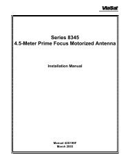
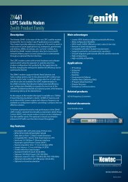
9600 SERIES (1 RU) – REAR PANEL<br />
AC voltage<br />
input/fuse<br />
IF monitor output<br />
connector<br />
Local oscillator<br />
frequency/power<br />
monitor test points<br />
RF signal monitor<br />
output connector<br />
(Option 2A only)<br />
Summary<br />
alarm<br />
connector<br />
Remote<br />
interface<br />
connector<br />
Reference<br />
frequency<br />
adjust<br />
Ground lug<br />
IF<br />
connector<br />
RF<br />
connector<br />
Redundancy<br />
alarm<br />
connector<br />
Remote<br />
interface<br />
connector<br />
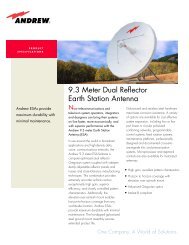
9400 SERIES (2 RU) – REAR PANEL<br />
AC voltage<br />
input/fuse<br />
Fan<br />
Remote<br />
interface<br />
connector<br />
Internal reference<br />
output connector<br />
(Option 23B only)<br />
Summary<br />
alarm<br />
connector<br />
IF monitor<br />
output<br />
connector<br />
RF signal monitor<br />
output connector<br />
(Option 2A only)<br />
Ground lug<br />
Internal/external<br />
reference<br />
select switch<br />
(Option 23C only)<br />
Remote<br />
interface connector<br />
(RS485, RS422 only)<br />
Reference<br />
frequency adjust<br />
Redundancy<br />
alarm<br />
connector<br />
External reference input<br />
connector (Options 23A,<br />
23B, 23C, 23D only)<br />
RF<br />
connector<br />
IF<br />
connector<br />
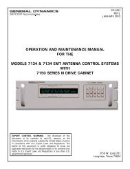
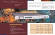
PHASE NOISE<br />
These phase noise curves are indicative of<br />
typical performance for a group of converters.<br />
If specific phase noise data is required for a<br />
converter, please consult the factory.<br />
TYPICAL PHASE NOISE CHARACTERISTICS (1.0 Hz BANDWIDTH)<br />
-30<br />
IESS-308/309<br />
-50<br />
4<br />
-70<br />
3<br />
-90<br />
2<br />
-110<br />
1<br />
-130<br />
PHASE NOISE (dBc/Hz)<br />
-150<br />
10 100 1K 10K 100K 1M 10M<br />
FREQUENCY OFFSET FROM CARRIER (Hz)
OPTIONS (CONT.)<br />
17. Remote control.<br />
A. RS422.<br />
B. RS485 (supplied as standard).<br />
C. RS232.<br />
D. Contact closure selection of up to sixteen preprogrammed frequencies.<br />
F. IEEE-488.<br />
G. BCD contact closure.<br />
18. Multiple IF outputs (D-9401-1, D-9401-2 only).<br />
18-2: Two IF outputs.<br />
18-3: Three IF outputs.<br />
18-4: Four IF outputs.<br />
18-5: Five IF outputs.<br />
18-6: Six IF outputs.<br />
18-7: Seven IF outputs.<br />
18-8: Eight IF outputs.<br />
19. Input prime voltage -48 VDC.<br />
Connector MS3102E10SL-3P<br />
Pin A: -48 VDC<br />
Pin B: Common<br />
Pin C: Chassis ground<br />
20. Switchable 70 MHz and 140 MHz IF frequencies (9400 Series only).<br />
Two IF connectors provided at rear panel (BNC female). Selection of IF frequency is available from<br />
the front panel and over the remote bus. Unit panel height is 5.25”.<br />
22. Dedicated remote control panel.<br />
Provides remote control and status over a dedicated RS485 bus. Option 17B (RS485 remote bus)<br />
must be ordered.<br />
23. 5 MHz reference configuration (9400 Series only).<br />
A. No internal 5 MHz reference is provided. A rear panel BNC female connector is provided for<br />
external 5 MHz input (+4 ±3 dBm).<br />
B. An internal 5 MHz reference is provided. The internal 5 MHz reference is brought out of and<br />
back into the rear panel with a “U link” coaxial cable (BNC connectors). This allows, after “U<br />
link” removal, insertion of an external 5 MHz reference input (+4 ±3 dBm).<br />
C. Internal/external reference selection.<br />
An SPDT switch is used to select either the internal 5 MHz reference or an external 5 MHz reference.<br />
External 5 MHz reference input is through a rear panel BNC female connector (+4 ±3<br />
dBm). Reference selection is controlled from a rear panel toggle switch.<br />
D. Automatic reference switchover.<br />
An internal 5 MHz reference and rear panel connector for external reference input (+4 ±3 dBm)<br />
is provided. The converter oscillators will lock to the external reference. If external reference is<br />
not present, the converter oscillators will automatically lock to the internal reference.<br />
Notes:<br />
Missing option numbers are not applicable to this product.<br />
For literature describing local control (front panel) and remote control (bus protocols), refer to<br />
MITEQ’s Technical Note 25T010 (9400 Series) and 25T009 (9600 Series).
OPTIONS<br />
2. A. RF signal monitor.<br />
Rear panel RF connector (SMA) with -20 dBc nominal level.<br />
4. A. 140 MHz IF frequency.<br />
Bandwidth: 80 MHz minimum<br />
Flatness: 0.75 dB/76 MHz<br />
Group delay (±36 MHz)<br />
Linear: 0.025 ns/MHz<br />
Parabolic: 0.0035 ns/MHz 2<br />
Ripple: 1 ns peak-to-peak<br />
IF return loss (140 ±40 MHz): 20 dB minimum<br />
Gain slope: 0.04 dB/MHz maximum (10 MHz minimum)<br />
B. 160 MHz IF frequency (D-9401-1, D-9401-2 only).<br />
Bandwidth: 100 MHz minimum<br />
Flatness: 1.0 dB/100 MHz<br />
Group delay (±50 MHz)<br />
Linear: 0.02 ns/MHz<br />
Parabolic: 0.0028 ns/MHz 2<br />
Ripple: 1 ns peak-to-peak<br />
IF return loss (160 ±50 MHz): 20 dB minimum<br />
Gain slope: 0.04 dB/MHz maximum (10 MHz minimum)<br />
5. Group delay equalization.<br />
A. 70 MHz IF, 1.0 ns peak-to-peak maximum ±18 MHz.<br />
B. 140 MHz IF, 2.0 ns peak-to-peak maximum ±36 MHz.<br />
C. 160 MHz IF, 3.0 ns peak-to-peak maximum ±50 MHz (D-9401-1, D-9401-2 only).<br />
8. LO level alarm (9400 Series only).<br />
Summary alarm is generated for loss of power in any of the required local oscillators.<br />
10. Higher frequency stability reference.<br />
A. ±1 x 10 -8 , 0 to 50°C,<br />
5 x 10 -9 /day typical (fixed temperature after 24 hour on time).<br />
B. ±5 x 10 -9 , 0 to 50°C,<br />
1 x 10 -9 /day typical (fixed temperature after 24 hour on time).<br />
C. ±2 x 10 -9 , 0 to 50°C,<br />
1 x 10 -9 /day typical (fixed temperature after 24 hour on time).<br />
11. Increased output power (upconverters).<br />
A. 5 dBm minimum power output 1 dB <strong>com</strong>pression, IF/RF gain is 20 dB typical.<br />
B. 10 dBm minimum power output 1 dB <strong>com</strong>pression, IF/RF gain is 30 dB typical for C- and X-band,<br />
and 26 dB typical for Ku-band.<br />
Specification of signal independent spurious increases with increase in IF/RF gain (e.g., if without<br />
option, specification is -90 dBm maximum, an increase of 10 dB in gain (Option 11A) will result in<br />
signal independent spurious of -80 dBm maximum).<br />
15. 50 ohm IF impedance.<br />
16. Higher gain option (downconverters).<br />
A. 45 dB nominal RF/IF gain.<br />
C. 55 dB nominal RF/IF gain.<br />
Specification of signal independent spurious increases with increase in RF/IF gain (e.g., if without<br />
option, specification is -90 dBm maximum, an increase of 15 dB in gain (Option 16A) will result in<br />
signal independent spurious of -75 dBm maximum).
SYNTHESIZED<br />
COMMUNICATION CONVERTERS<br />
PRIMARY POWER REQUIREMENTS<br />
Voltage .................................................. 100, 120, 220, 230/240 VAC +10%, -13%<br />
(rear panel selectable), 250 VAC maximum<br />
Frequency ............................................. 47–63 Hz<br />
Power consumption............................... 120 W typical<br />
SUMMARY ALARM<br />
Contact closure/open for DC voltage alarm<br />
Contact closure/open for DC voltage and/or LO alarm<br />
PHYSICAL<br />
Weight ................................................... 20 pounds nominal<br />
Overall dimensions................................ 19" x 3.5" panel x 22" maximum (chassis depth 20")<br />
1.75” panel height for 9600 Series<br />
Rear panel connectors<br />
RF...................................................... N female for RF below 10.0 GHz,<br />
SMA female for RF above 10.0 GHz<br />
IF ....................................................... BNC female<br />
IF signal monitor................................ BNC female<br />
Remote interface ............................... DEM-9S for RS485 and RS422,<br />
DB-25P for RS232,<br />
DB-25S for contact closure, and BCD contact closure,<br />
IEEE-488 receptacle for GPIB<br />
Summary alarm ................................. DE-9P<br />
Redundancy alarm ............................ DE-9P<br />
LO frequency/power monitor ............ SMA female (front panel 9400 Series)<br />
ENVIRONMENTAL<br />
Operating<br />
Ambient temperature......................... 0 to 50°C<br />
Relative humidity ............................... Up to 95% at 30°C<br />
Atmospheric pressure ....................... Up to 10,000 feet<br />
Nonoperating<br />
Ambient temperature......................... -50 to +70°C<br />
Relative humidity ............................... Up to 95% at 40°C<br />
Atmospheric pressure ....................... Up to 40,000 feet<br />
Shock and vibration........................... Normal handling by <strong>com</strong>mercial carriers<br />
D-148F<br />
100 Davids Drive, Hauppauge, NY 11788<br />
TEL.: (631) 436-7400 • FAX: (631) 436-7431/436-7430<br />
www.miteq.<strong>com</strong>