Enviroguard Manual B Engine
Enviroguard Manual B Engine
Enviroguard Manual B Engine

Create successful ePaper yourself
Turn your PDF publications into a flip-book with our unique Google optimized e-Paper software.
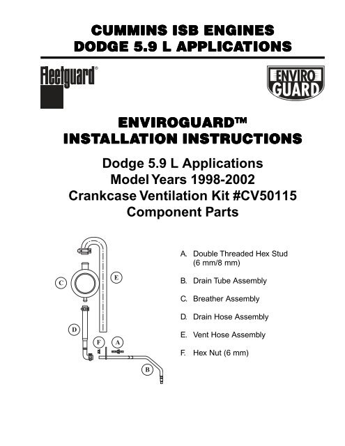
CUMMINS ISB ENGINES<br />
DODGE 5.9 L APPLICATIONS<br />
ENVIROGUARD<br />
INSTALLA<br />
ALLATION INSTRUCTIONS<br />
Dodge 5.9 L Applications<br />
Model Years 1998-2002<br />
Crankcase Ventilation Kit #CV50115<br />
Component Parts<br />
A. Double Threaded Hex Stud<br />
(6 mm/8 mm)<br />
C<br />
MADE IN USA<br />
U.S. PATENT NO. 8,380,730<br />
E<br />
B. Drain Tube Assembly<br />
CV50115<br />
C. Breather Assembly<br />
D. Drain Hose Assembly<br />
D<br />
F<br />
A<br />
E. Vent Hose Assembly<br />
F. Hex Nut (6 mm)<br />
B
Installation Steps - Dodge 5.9 L <strong>Engine</strong><br />
2<br />
1<br />
Removing the Existing Breather Vent System<br />
Step 1 - Disconnect the vent hose and bottle from the<br />
existing breather vent assembly. Clean the front of the<br />
engine to remove dirt and debris. Remove the hex nut<br />
from the stud holding the “P” clip and bottle in place.<br />
Remove the bottle from the “P” clip. Retain the clip<br />
and the hex nut. Both will be used later when<br />
installing the new vent hose.<br />
1<br />
1<br />
“P” Clip<br />
Steps 1 & 2<br />
Step 2 - Remove the existing breather vent assembly<br />
from the engine gear cover plate by turning the<br />
assembly in a counter clockwise direction. (The<br />
assembly has threads on the inner body and is screwed<br />
into the cover plate.)<br />
3<br />
Step 3 - Once the assembly has been removed, clean<br />
the mounting surface and threaded opening to ensure<br />
all oil and dirt have been removed.<br />
Step 4 - Remove the existing hex bolt from the gear<br />
cover plate as shown. From the front of the engine, the<br />
location of the bolt is directly right of the existing stud.<br />
4<br />
Steps 3 & 4<br />
Installing the New Crankcase Ventilation System<br />
and Drain Tube Assembly<br />
A<br />
5<br />
Step 5 - Install the double threaded hex stud (8 mm<br />
end) into the bolt opening on the gear cover plate.<br />
Tighten the stud until it is seated tightly against<br />
the plate.<br />
Use Pin to<br />
Clear Port<br />
Steps 5, 6 and 7<br />
7<br />
7<br />
6<br />
Plug<br />
Step 6 - Locate the open dipstick port boss at the bottom<br />
of the cylinder block (above the pan rail). The open<br />
port boss is at the front of the engine. Clean the area<br />
thoroughly. To gain better access to this area of the<br />
engine, remove the mounting bolts and “P” clips<br />
holding the electrical harness in place.<br />
Step 7 - Locate the frost plug in the port boss and<br />
remove it carefully to ensure no foreign contaminants<br />
enter the crankcase. After removing the plug, insert a<br />
.375 inch (9.5 mm) pin into the opening to ensure the<br />
hole is free of any foreign matter. The opening must<br />
be completely free of any obstructions (burrs and<br />
dirt) before proceeding.
10<br />
B<br />
9<br />
8<br />
Step 8 - Position the drain tube assembly and insert<br />
the end with the O-ring into the open port boss. Push<br />
the tubing into the port boss until the O-ring is fully<br />
seated against the bead on the drain tube. To ensure<br />
the O-ring properly seals against the port boss,<br />
apply oil to the ring.<br />
Step 9 - Rotate the drain tube assembly, positioning<br />
the bracket attached to the tubing over the end of the<br />
original hex stud.<br />
Steps 8, 9 and 10<br />
Step 10 - Ensure the bracket is positioned correctly<br />
over the hex stud as shown. Secure the bracket with<br />
the hex nut (6 mm) removed earlier. Replace the<br />
electrical harness by reattaching the “P” clips to<br />
the engine with the mounting bolts removed earlier.<br />
Installing the Breather Assembly<br />
C<br />
Step 11 - Install the new breather assembly by first<br />
applying a small amount of oil to the inner gasket<br />
surface of the breather assembly.<br />
11<br />
Inner Gasket<br />
Surface (White)<br />
Step 11<br />
C<br />
12<br />
Step 12 - Position the breather assembly in the cover<br />
plate opening and thread the assembly into the opening<br />
by turning it in a clockwise direction. Continue turning<br />
until the assembly is seated against the cover plate and<br />
the one inch OD (25 mm) vent opening is pointing<br />
straight up.<br />
Step 12
Installing the Drain Hose Assembly<br />
Step 13 - Attach the top of the drain hose onto the<br />
breather assembly. Position the clamp at the top of the<br />
hose and secure with the clamp.<br />
14<br />
13<br />
D<br />
Steps 13 & 14<br />
Step 14 - Next, position the lower end of the drain<br />
hose over the metal drain tube assembly.<br />
To attach the drain hose to the drain tube, push the<br />
elbow portion of the drain hose over the drain tube by<br />
releasing tension on the hose clamp. The drain hose<br />
should cover at least 1 inch of the drain tube. Secure<br />
with the clamp. Inspect to ensure the drain hose<br />
assembly is free of any kinks or bends.<br />
16<br />
15<br />
E<br />
Installing the Vent Hose Assembly<br />
Step 15 - Attach the vent hose assembly to the top outlet<br />
of the breather assembly. Position the clamp at the<br />
bottom of the hose and secure with the clamp.<br />
F<br />
Step 16 - Slip the original “P” clip over the end of the<br />
vent hose. Position the hose and clip to the right of the<br />
original hex stud. Position the clip over the new stud;<br />
secure with the hex nut provided.<br />
Inspect the vent hose to ensure it is pointed downward<br />
and is free of any kinks or bends. Ensure the vent hose<br />
is clear of the fan or any other rotating parts.<br />
Post Installation<br />
After installing the kit, start the engine and check<br />
for any oil leaks. Periodically, check all connections<br />
(hoses, oil drain tubes) to ensure the system is<br />
functioning properly.<br />
Steps 15 & 16<br />
No maintenance is required after installation.<br />
LT32519<br />
March 2003<br />
©Fleetguard, Inc. 2003<br />
Printed in U.S.A.<br />
For more information, call Customer Assistance<br />
at 1-800-22FILTER (1-800-223-4583, fax 1-800-999-8664)<br />
or visit us at www.fleetguard.com