UMTS Network Architecture - Tektronix
UMTS Network Architecture - Tektronix
UMTS Network Architecture - Tektronix

You also want an ePaper? Increase the reach of your titles
YUMPU automatically turns print PDFs into web optimized ePapers that Google loves.
<strong>UMTS</strong> Protocols and Protocol Testing<br />
▲<br />
Primer<br />
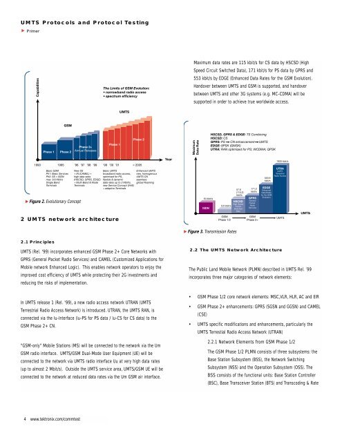
Maximum data rates are 115 kbit/s for CS data by HSCSD (High<br />
Speed Circuit Switched Data), 171 kbit/s for PS data by GPRS and<br />
553 kbit/s by EDGE (Enhanced Data Rates for the GSM Evolution).<br />
Handover between <strong>UMTS</strong> and GSM is supported, and handover<br />
between <strong>UMTS</strong> and other 3G systems (e.g. MC-CDMA) will be<br />
supported in order to achieve true worldwide access.<br />
▲<br />
Figure 2. Evolutionary Concept<br />
2 <strong>UMTS</strong> network architecture<br />
▲<br />
Figure 3. Transmission Rates<br />
2.1 Principles<br />
<strong>UMTS</strong> (Rel. '99) incorporates enhanced GSM Phase 2+ Core <strong>Network</strong>s with<br />
GPRS (General Packet Radio Services) and CAMEL (Customized Applications for<br />
Mobile network Enhanced Logic). This enables network operators to enjoy the<br />
improved cost efficiency of <strong>UMTS</strong> while protecting their 2G investments and<br />
reducing the risks of implementation.<br />
2.2 The <strong>UMTS</strong> <strong>Network</strong> <strong>Architecture</strong><br />
The Public Land Mobile <strong>Network</strong> (PLMN) described in <strong>UMTS</strong> Rel. ´99<br />
incorporates three major categories of network elements:<br />
In <strong>UMTS</strong> release 1 (Rel. '99), a new radio access network UTRAN (<strong>UMTS</strong><br />
Terrestrial Radio Access <strong>Network</strong>) is introduced. UTRAN, the <strong>UMTS</strong> RAN, is<br />
connected via the Iu-Interface (Iu-PS for PS data / Iu-CS for CS data) to the<br />
GSM Phase 2+ CN.<br />
"GSM-only" Mobile Stations (MS) will be connected to the network via the Um<br />
GSM radio interface. <strong>UMTS</strong>/GSM Dual-Mode User Equipment (UE) will be<br />
connected to the network via <strong>UMTS</strong> radio interface Uu at very high data rates<br />
(up to almost 2 Mbit/s). Outside the <strong>UMTS</strong> service area, <strong>UMTS</strong>/GSM UE will be<br />
connected to the network at reduced data rates via the Um GSM air interface.<br />
• GSM Phase 1/2 core network elements: MSC,VLR, HLR, AC and EIR<br />
• GSM Phase 2+ enhancements: GPRS (SGSN and GGSN) and CAMEL<br />
(CSE)<br />
• <strong>UMTS</strong> specific modifications and enhancements, particularly the<br />
<strong>UMTS</strong> Terrestial Radio Access <strong>Network</strong> (UTRAN)<br />
2.2.1 <strong>Network</strong> Elements from GSM Phase 1/2<br />
The GSM Phase 1/2 PLMN consists of three subsystems: the<br />
Base Station Subsystem (BSS), the <strong>Network</strong> Switching<br />
Subsystem (NSS) and the Operation Subsystem (OSS). The<br />
BSS consists of the functional units: Base Station Controller<br />
(BSC), Base Transceiver Station (BTS) and Transcoding & Rate<br />
4 www.tektronix.com/commtest
<strong>UMTS</strong> Protocols and Protocol Testing<br />
▲<br />
Primer<br />
Adaptation Unit (TRAU). The NSS consists of the functional<br />
units: Mobile Services switching Center (MSC), Visitor Location<br />
Register (VLR), Home Location Register (HLR), Equipment<br />
Identity Register (EIR) and the Authentication Center (AC). The<br />
MSC provides functions such as switching, signaling, Paging,<br />
and Inter-MSC Handover. The OSS consists of Operation &<br />
Maintenance Centers (OMC), which are used for remote and<br />
centralized Operation, Administration and Maintenance tasks.<br />
2.2.2 <strong>Network</strong> Elements from GSM Phase 2+<br />
GPRS (General Packet Radio Services)<br />
The most important evolutionary step of GSM towards <strong>UMTS</strong> is<br />
GPRS. GPRS introduces Packet Switching (PS) into the GSM<br />
Core <strong>Network</strong> and allows direct access to Packet Data<br />
<strong>Network</strong>s (PDN). This enables high data rate PS transmission<br />
well beyond the 64 kbit/s limit of ISDN through the GSM CN, a<br />
necessity for <strong>UMTS</strong> data transmission rates of up to 2 Mbit/s.<br />
GPRS prepares and optimizes the CN for high data rate PS<br />
transmission, as does <strong>UMTS</strong> with UTRAN over the RAN. Thus,<br />
GPRS is a prerequisite for the <strong>UMTS</strong> introduction.<br />
Two functional units extend the GSM NSS architecture for<br />
GPRS PS services: the Gateway GPRS Support Node (GGSN)<br />
and the Serving GPRS Support Node (SGSN).<br />
The GGSN has functions comparable to a GMSC. The SGSN<br />
resides at the same hierarchical level as a VMSC/VLR and<br />
therefore performs comparable functions such as routing and<br />
mobility management.<br />
CAMEL (Customized Applications for Mobile network<br />
Enhanced Logic)<br />
CAMEL enables worldwide access to operator specific<br />
GSM BSS<br />
BTS<br />
TRAU<br />
A<br />
VLR<br />
PSTN<br />
Um<br />
Abis<br />
BSC<br />
IWF TC<br />
MSC<br />
GMSC<br />
ISDN<br />
BTS<br />
Uu<br />
UTRAN<br />
CSE VLR HLR AuC<br />
External<br />
<strong>Network</strong>s<br />
Node B<br />
Iu CS<br />
Gb<br />
UE<br />
(USIM)<br />
Iub<br />
RNC<br />
Iu PS<br />
SGSN<br />
Gn<br />
GGSN<br />
Gi<br />
PDN<br />
e.g. Internet,<br />
Intranet, X.25<br />
Node B<br />
Iur<br />
USIM & SIM for<br />
GSM, <strong>UMTS</strong> &<br />
<strong>UMTS</strong>/GSM<br />
Terminals<br />
Iub<br />
Iu<br />
▲<br />
Node B<br />
Figure 4. <strong>UMTS</strong> Phase 1 <strong>Network</strong><br />
RNC<br />
GSM Phase 2+ Core <strong>Network</strong><br />
IWF/TC: Interworking Function/Transcoder<br />
www.tektronix.com/commtest<br />
5
<strong>UMTS</strong> Protocols and Protocol Testing<br />
▲<br />
Primer<br />
Intelligent <strong>Network</strong> (IN) applications such as Prepaid, Call<br />
Screening, and Supervision. CAMEL is the primary GSM Phase<br />
2+ enhancement for the introduction of the <strong>UMTS</strong> Virtual<br />
Home Environment (VHE) concept. VHE is a platform for<br />
flexible service definition (collection of Service Creation Tools)<br />
that enables the operator to modify or enhance existing<br />
services and/or to define new services. Furthermore, VHE<br />
enables worldwide access to these operator-specific services<br />
in every GSM and <strong>UMTS</strong> PLMN and introduces Location Based<br />
Services (by interaction with GSM/<strong>UMTS</strong> Mobility Management).<br />
A CAMEL Service Environment (CSE) and a new CCS7<br />
protocol, the CAMEL Application Part (CAP) are required on the<br />
CN to introduce CAMEL.<br />
2.2.3 <strong>Network</strong> Elements from <strong>UMTS</strong> Phase 1<br />
As mentioned above, <strong>UMTS</strong> differs from GSM Phase 2+ mostly<br />
in the new principles for air interface transmission (W-CDMA<br />
instead of TDMA/FDMA). Therefore, a new radio access<br />
network called UTRAN must be introduced with <strong>UMTS</strong>. Only<br />
minor modifications, such as allocation of the transcoding<br />
function (TC) for speech compression to the CN, are needed in<br />
the Core <strong>Network</strong> to accommodate the change. The TC<br />
function is used together with an Interworking Function (IWF)<br />
for protocol conversion between the A and the Iu-CS interfaces.<br />
UTRAN (<strong>UMTS</strong> Terrestrial Radio Access <strong>Network</strong>)<br />
The <strong>UMTS</strong> standard can be seen as an extension of existing<br />
networks. Two new network elements are introduced in<br />
UTRAN, Radio <strong>Network</strong> Controller (RNC) and Node B. UTRAN is<br />
subdivided into individual Radio <strong>Network</strong> Systems (RNS), where<br />
each RNS is controlled by a Radio <strong>Network</strong> Controller (RNC).<br />
The RNC is connected to a set of Node B elements, each of<br />
which can serve one or several cells.<br />
Existing network elements, such as MSC, SGSN and HLR, can<br />
be extended to adopt the <strong>UMTS</strong> requirements, but RNC, Node<br />
B and the handsets must be completely new designs. RNC will<br />
become the replacement for BSC, and Node B fulfills nearly<br />
the same functionality as BTS. GSM and GPRS networks will<br />
Node B<br />
Iub<br />
RNC<br />
Radio <strong>Network</strong><br />
Controller<br />
Iub<br />
GSM Phase 2+<br />
Core <strong>Network</strong><br />
Uu<br />
Iu<br />
UE<br />
User<br />
Equipment<br />
Node B<br />
Iur<br />
MSC<br />
SGSN<br />
Iu<br />
Iub<br />
RNC<br />
Radio <strong>Network</strong><br />
Controller<br />
Node B<br />
<strong>UMTS</strong> Terrestrial Radio Access <strong>Network</strong><br />
▲<br />
Figure 5. UTRAN <strong>Architecture</strong><br />
6 www.tektronix.com/commtest
<strong>UMTS</strong> Protocols and Protocol Testing<br />
▲<br />
Primer<br />
be extended and new services will be integrated into an overall<br />
If another RNC is involved in the active connection through an<br />
network that contains both existing interfaces such as A, Gb,<br />
Inter-RNC Soft Handover, it is declared a Drift RNC (DRNC). The<br />
Abis and new interfaces that include Iu, Iub and Iur.<br />
DRNC is only responsible for the allocation of Code resources.<br />
<strong>UMTS</strong> defines four new open interfaces:<br />
• Uu: User Equipment (UE) to Node B (UTRA, the <strong>UMTS</strong> W-<br />
CDMA air interface)<br />
• Iu: RNC to GSM Phase 2+ Core <strong>Network</strong> interface<br />
A reallocation of the SRNC functionality to the former DRNC is<br />
possible (SRNS Relocation). The term Controlling RNC (CRNC)<br />
is used to define the RNC that controls the logical resources of<br />
its UTRAN access points.<br />
(MSC/VLR or SGSN)<br />
Iu-CS for circuit switched data<br />
Iu-PS for packet switched data.<br />
Node B is the physical unit for radio transmission/reception<br />
with cells. Depending on sectoring (Omni-/Sector Cells) one or<br />
more cells may be served by a Node B. A single Node B can<br />
• Iub: RNC to Node B interface<br />
support both FDD and TDD modes, and it can be co-located<br />
• Iur: RNC to RNC interface; not comparable to any<br />
interface in GSM<br />
The Iu, Iub and Iur interfaces are based on ATM transmission<br />
principles.<br />
with a GSM BTS to reduce implementation costs. Node B<br />
connects with the UE via the W-CDMA Uu radio interface and<br />
with the RNC via the Iub ATM-based interface. Node B is the<br />
ATM termination point.<br />
The Radio <strong>Network</strong> Controller (RNC) enables autonomous Radio<br />
Resource Management by UTRAN. It performs the same<br />
functions as the GSM Base Station Controller (BSC), providing<br />
central control for the Radio <strong>Network</strong> System (RNS) elements<br />
(RNC and Node Bs).<br />
The main task of Node B is the conversion of data to/from the<br />
Uu radio interface, including Forward Error Correction FEC,<br />
Rate Adaptation, W-CDMA Spreading/De-Spreading, and QPSK<br />
Modulation on the air interface. It measures quality and<br />
strength of the connection and determines the Frame Error<br />
The RNC handles protocol exchanges between Iu, Iur, and Iub<br />
interfaces and is responsible for centralized Operation &<br />
Rate (FER), transmitting these data to the RNC as a<br />
Measurement Report for Handover and Macro Diversity<br />
Maintenance of the entire RNS with access to the<br />
Operation SubSystem (OSS). Because the interfaces<br />
are ATM-based, the RNC switches ATM cells<br />
between them. The user’s circuit-switched and<br />
packet switched data coming from Iu-CS and Iu-PS<br />
interfaces are multiplexed together for multimedia<br />
transmission via Iur, Iub, and Uu interfaces to and<br />
Uu<br />
Uu<br />
Node B<br />
Uu<br />
Iub<br />
UTRAN: TS 25.401<br />
from the User Equipment (UE).<br />
Node B<br />
D-RNC<br />
The RNC uses the Iur interface, which has no<br />
equivalent in GSM BSS, to autonomously handle<br />
100% of the Radio Resource Management (RRM),<br />
eliminating that burden from the Core <strong>Network</strong>.<br />
Serving control functions such as Admission, RRC<br />
connection to the UE, Congestion and<br />
S-RNC<br />
• Combining/Splitting<br />
• Active Set<br />
• RR Allocation<br />
Core <strong>Network</strong> CN<br />
Iub<br />
Iu<br />
RNC<br />
Iub<br />
Node B<br />
• Only RR Allocation<br />
Iur<br />
RNC Functions:<br />
• Autonomous RRM<br />
• ATM Switching & Multiplexing<br />
• Control Over RNS<br />
• O&M Interface<br />
RNC<br />
Iu<br />
Handover/Macro Diversity are managed entirely by a<br />
single Serving RNC (SRNC).<br />
▲<br />
Figure 6. RNC Functions<br />
www.tektronix.com/commtest<br />
7
<strong>UMTS</strong> Protocols and Protocol Testing<br />
▲<br />
Primer<br />
Combining. The Node B is also<br />
responsible for the FDD Soft<br />
Handover. This Micro Diversity<br />
combining is carried out<br />
independently, eliminating the need<br />
for additional transmission capacity<br />
in the Iub.<br />
The Node B also participates in<br />
Power Control, as it enables the UE<br />
to adjust its power using DL TPC<br />
commands via the Inner Loop Power<br />
Control on the basis of UL Transmit<br />
Power Control TPC information. The<br />
predefined values for Inner Loop<br />
Power Control are derived from the<br />
RNC via Outer Loop Power Control.<br />
▲<br />
Uu<br />
Node B<br />
Iub<br />
RNC<br />
Figure 7. Node B Functions<br />
Physical Node<br />
• Connected via Uu/Iub<br />
• Support of 1/several cells<br />
• FDD and/or TDD Mode operation<br />
• ATM Termination (Iub)<br />
• Data conversion for Uu transmission<br />
• Inner Loop PC<br />
• Measurement reports<br />
• FDD: Micro-Diversity (Softer HoV)<br />
The <strong>UMTS</strong> UE is based on the same principles as the GSM MS<br />
– the separation between ME and the <strong>UMTS</strong> SIM card (USIM).<br />
The following figure shows the user equipment functions.<br />
UE<br />
UE as Node B Counterpart:<br />
• FEC (Encoding & Interleaving)<br />
• Power Control (Open & Inner Loop)<br />
• Radio Measurement (FER, SIR, Quality & Power)<br />
• Spreading/De-spreading<br />
• Modulation/De-modulation<br />
UE as RNC Counterpart:<br />
• BEC (Acknowledged Mode; NRT)<br />
• RRC (Radio Resource Control)<br />
• Handover (CS) & Cell Selection (PS)<br />
• De-/Ciphering<br />
• ...<br />
Node B<br />
RNC<br />
UE<br />
UE as CN Counterpart:<br />
• Mobility Management (Location Registration, Authentication,<br />
IMEI Check, Attach/Detach)<br />
• Session Management (PDP) Context De-/Activation)<br />
• Bearer Negotiation/Service Request<br />
• ...<br />
MSC/VLR/EIR<br />
SGSN<br />
▲<br />
Figure 8. UE Functions<br />
The UE is the counterpart to the various network elements in<br />
many functions and procedures.<br />
8 www.tektronix.com/commtest