ECI1 DUAL MONO INTEGRATED AMPLIFIER - Electrocompaniet
ECI1 DUAL MONO INTEGRATED AMPLIFIER - Electrocompaniet
ECI1 DUAL MONO INTEGRATED AMPLIFIER - Electrocompaniet

You also want an ePaper? Increase the reach of your titles
YUMPU automatically turns print PDFs into web optimized ePapers that Google loves.
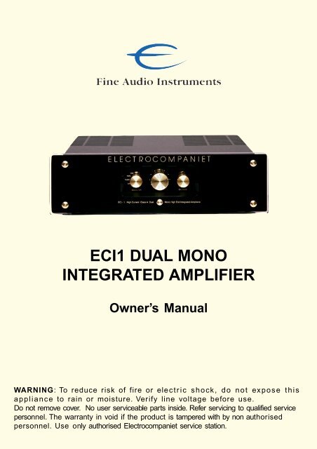
<strong>ECI1</strong> <strong>DUAL</strong> <strong>MONO</strong><br />
<strong>INTEGRATED</strong> <strong>AMPLIFIER</strong><br />
Owner’s Manual<br />
WARNING: To reduce risk of fire or electric shock, do not expose this<br />
appliance to rain or moisture. Verify line voltage before use.<br />
Do not remove cover. No user serviceable parts inside. Refer servicing to qualified service<br />
personnel. The warranty in void if the product is tampered with by non authorised<br />
personnel. Use only authorised <strong>Electrocompaniet</strong> service station.
Welcome to the world of <strong>Electrocompaniet</strong><br />
We sincerely thank you for selecting an amplifier from <strong>Electrocompaniet</strong>. We hope<br />
you will enjoy years of listening pleasure and true high end musical performance<br />
from your audio system. Kindly read this owners manual to familiarise yourself with<br />
the set before operation.<br />
The <strong>Electrocompaniet</strong> Story<br />
<strong>Electrocompaniet</strong> was founded in 1973 in Oslo, Norway, to manufacture an amplifier<br />
designed by Per Abrahamsen. The design were based upon a new approach to<br />
transistor amplifier design developed by Dr. Matti Otala and Jan Lohstro.<br />
It had long been recognised that transistor amplifiers had a characteristic sound that<br />
many audiophiles and music lovers found unnatural.<br />
Dr. Otala and Mr. Lohstro analysed transistor amplifiers to determine what actually<br />
created the “transistor sound” in general transistorised designs. The results of their<br />
innovative design work were incorporated in the first <strong>Electrocompaniet</strong> design, the<br />
legendary 25 watt amplifier.<br />
This product were the first commercial transistor amplifier to use this new design<br />
approach, and the amplifier was immediately recognised as dramatically more musical<br />
sounding than any other transistor amplifier. The same design philosophy, has<br />
been constantly updated by additional research and development. This philosophy<br />
form the basis of all the current <strong>Electrocompaniet</strong> Ampliwire and Preampliwire Dual<br />
Mono Balanced designs.<br />
<strong>Electrocompaniet</strong> have always given extensive listening test of all it’s designs the<br />
highest priority. Every product designed by our engineers must meet the varied and<br />
exacting standards of the listening panel, carefully selected to represent a cross<br />
section of musical taste and experience. <strong>Electrocompaniet</strong> designs go back and<br />
forth between the design laboratory and the listening panel until both engineers and<br />
listeners are completely satisfied, and ensured the that the design has met it’s<br />
technical and sonic objectives.<br />
All <strong>Electrocompaniet</strong> products are handmade by highly skilled technicians, and<br />
extensively tested for maximum performance and reliability.<br />
Final adjustments are made only after an extended period of operation to insure the<br />
best possible performance under conditions similar to those of actual use.<br />
<strong>Electrocompaniet</strong> Ampliwire and Preampliwire are sold in more than 25 countries ,<br />
providing the ultimate listening pleasure to dedicated music lovers world-wide.
The design features of Ampliwire ECI 1<br />
After the <strong>Electrocompaniet</strong> 25 watt amplifier had established a new standard for<br />
transistor amplifiers, research was undertaken to find ways to make the amplifier<br />
even better, and to extend its highly musical sound quality to more powerful amplifier<br />
designs. The engineers at <strong>Electrocompaniet</strong> were not satisfied by only reducing the<br />
commonly recognised types of distortion to low levels. They recognised that distortion<br />
appears in many forms, and that distortion was still audible in listening tests even<br />
when conventional categories of distortion were at astonishingly low levels.<br />
Traditionally, designers increased feedback to make a larger portion of the output<br />
signal control the amplifiers response. Our listening tests showed us that simply<br />
applying more feedback was not the answer. In fact, as one kind of distortion went<br />
down, other parameters would be adversely affected, leading to an overall<br />
degradation of sound quality. We knew that the other conventional design approach<br />
of eliminating feedback completely was not the answer either, because this would<br />
cause high distortion levels, and as a result would produce a “woolly” sound.<br />
The answer to the dilemma was found in a novel approach to feedback theory. We<br />
developed a feedback concept that allowed local feedback to be applied around<br />
individual stages of the amplifier circuit. This approach allowed us to avoid the sonic<br />
disadvantages of overall feedback from output to input. The concept was further<br />
developed to reduce phase- and interphase distortion between stages of the<br />
amplifier as well. We were able to concentrate the loop feedback on the stages of the<br />
amplifier where it resulted in audible improvement.<br />
Stability margins were also expanded because feedback no longer affected the frequency<br />
response. The use of this concept of individual gain blocks - complex in<br />
design but simple in function - allowed us to reduce distortion to minute values in all<br />
the products.<br />
The amplifier is divided into two separate sections or gain blocks. The input block is<br />
a transconductance amplifier without overall feedback. This avoids large output<br />
current being fed back to the input, and mixed with the minute input signal. The output<br />
block is a transresistance amplifier with parallel feedback. This is done to prevent<br />
higher frequencies than the feedback loop can handle, from entering the loop. An<br />
approach like this will prevent Transient Inter modulation Distortion (TIM) and<br />
Slewing Induced Distortion (SID), eliminating the need for an extremely wide<br />
bandwidth.<br />
All stages work in Class A with an efficiency of less than 0,1%. The power supply of<br />
the ECI 1 consists of two 500 VA toroidal transformer. Furthermore, the power<br />
supply consists of a 40.000 micro farad reservoir divided into four 10.000 micro farad<br />
capacitors in parallel with 4,7 and 0,1 micro farad polycarbonate- and polypropylene<br />
capacitors.
Unpacking the amplifier:<br />
Immediately upon receipt of the amplifier, inspect the carton for possible damage<br />
during shipment. If the carton is visibly damaged, a claim must be filed with the carrier<br />
as soon as possible.<br />
Unpack the unit carefully, and please do remember to save all packaging materials<br />
for future shipment. The carton and packaging have been designed to offer the<br />
safest possible protection when transporting your amplifier.<br />
The content of the carton is as follows:<br />
1 pcs <strong>Electrocompaniet</strong> Ampliwire ECI 1<br />
1 pcs AC power cord<br />
1 Owners Manual<br />
1 pcs Spare fuse,5.0 AT slow-blow 5x20mm (120V AC)<br />
2.5 AT slow-blow 5x20mm (220V AC)<br />
The actual spare fuse is located inside the AC 3 pin receptacle.<br />
Connecting the AW ECI 1<br />
Connecting to mains<br />
Check that the mains voltage printed on the rear panel of the amplifier corresponds<br />
with the line voltage in the territory were you intend to use your amplifier.<br />
How to avoid damages<br />
A good operating practice is to turn off all equipment before any connections or<br />
disconnection’s are made. Do not under any circumstances connect or disconnect<br />
equipment when power is turned on. If you insist on connecting or disconnecting<br />
while power is turned on, you should be aware that the design of the RCA plug<br />
generates a large transient when inserting the plug. This could damage both the<br />
speakers and the amplifier.<br />
The rear panel<br />
The rear panel of the Ampliwire ECI 1 contains all input and output connectors. The<br />
printed rear panel clearly indicates the functions of each connector. The preamplifier<br />
section of the ECI 1 is designed for line levels only, and a turntable can not be<br />
connected to the unit. A separate phono stage must be connected between the<br />
turntable and the ECI 1. Any input can be used.<br />
A separate power amplifier may be connected to the connector marked OUT .<br />
This output is controlled by the volume/ balance control.
Operating instructions:<br />
How to turn on your system<br />
You should always turn on your equipment in this order: Signal source devices (CD,<br />
tuner, etc) are turned on first. Allow 30 seconds of preheating before you turn on your<br />
amplifier.When turning your system off, you should start by switching off your<br />
amplifier<br />
and finally your signal source devices<br />
After switching on the amplifier, there will be a 5 seconds delay before the speakers<br />
are connected. This will prevent large turn on/off transients to reach the speakers.<br />
Replacing a blown main fuse:<br />
Always remove the AC cord from the Inlet<br />
The main fuse is located inside a small drawer in the AC inlet of the unit. If, for some<br />
reason the fuse blows, turn the unit off, and remove the AC cord from the inlet.<br />
Open the drawer with a small screwdriver and remove the broken fuse. The spare<br />
fuse is located in the hole in front of the main fuse. Push the new fuse gently out of<br />
the hole, and place it in correct position (where the blown fuse was removed). Push<br />
the drawer gently back to the closed position, connect the power cord and turn the<br />
unit on.<br />
Never replace a blown fuse with other values than printed on the unit.<br />
Warning:<br />
The amplifier will be warm.<br />
Due to the high class A operating point used in the <strong>Electrocompaniet</strong> design, it is<br />
normal that the amplifier feels warm. Proper ventilation will be needed, and the<br />
amplifier should not be covered in. A good rule is to allow 1 - 2 inches of air<br />
sidewise, and 2 - 3 inches above the amplifier.<br />
If placing the amplifier on the floor, be aware of carpets that can obstruct the<br />
ventilation underneath the amplifier.
Service Policy:<br />
When service is needed<br />
Your dealer will have all relevant information about the service centers in your area,<br />
and will ensure that your unit is serviced without delay. It is our general policy to have<br />
your amplifier returned to you within 5 working days. This is an average time, and<br />
could vary locally, depending on the work load at the service center.<br />
If, for some reason, there are no service facilities available in your country, please<br />
ship the amplifier to the following address:<br />
ELECTROCOMPANIET AS<br />
BREIVIKVEIEN 7<br />
N-4120 TAU, NORWAY<br />
FAX +47 51 74 10 10<br />
E-mail : elcomp@electrocompaniet.no<br />
You are responsible for all shipping charges, insurance, re-importation to your country,<br />
and duty arrangements. When shipping a product to the factory for service,<br />
always include the following:<br />
1) A sales slip or other proof of purchase if repair is claimed under<br />
warranty.<br />
2) A proforma invoice with value of the goods, stating that the amplifier<br />
is returned to Norway for repair.<br />
3) An accompanying letter describing faults, symptoms, or problems<br />
with the amplifier.<br />
4) Always ship the amplifier in its original carton and packaging material<br />
to prevent damage in transit.<br />
<strong>Electrocompaniet</strong> will not accept responsibility for any damage caused in transit, no<br />
matter how ever caused.<br />
If you require further information concerning the amplifier operation, or if you have<br />
any questions related to service, please do not hesitate to contact your dealer or<br />
national <strong>Electrocompaniet</strong> distributor.
Technical Specifications ECI 1 :<br />
The following technical data were measured on randomised test objects and are<br />
typical data. All measurements are made with the following equipment:<br />
Distortion analyser:<br />
Tektronix AA501<br />
Oscilloscope: Tektronix 468<br />
Oscillator:<br />
Tektronix SG505<br />
Frequency counter: Rascal 9838<br />
Phase meter:<br />
Hewlett Packard 3575A<br />
Preamplifier section<br />
Input impedance<br />
47 kOhm<br />
THD (1kHz 1V input, 1V output) 0,001%<br />
Max. input<br />
> 14 V RMS<br />
Channel separation (1V output at 1kHz) > 90dB<br />
Equivalent input noise < 3 µV<br />
Output impedance<br />
100 Ohm<br />
Amplifier section<br />
Main voltage 120 V / 240 V. Clipping point of the amplifier is set to a level where total<br />
harmonic distortion (THD) is 0.2 %.<br />
Output Impedance (20 Hz - 20 kHz) < 0,01 Ohm<br />
Input sensitivity for rated output 0.4 V<br />
Max. Peak current<br />
> 80 A<br />
THD (measured at 1 kHz half power, 8 Ohm) < 0,001 %<br />
THD (measured at 1 kHz -1 dB, 8 Ohm) < 0,001 %<br />
Noise (measured with both inputs shorted)<br />
400Hz - 30kHz : 150 µV<br />
10 Hz - 30 kHz : 180 µV<br />
Rated output power<br />
10 % change in line voltage will give app. 20 % change in output power.<br />
8 Ohm 2 x 100 W<br />
4 Ohm 2 x 200 W<br />
2 Ohm 2 x 350 W<br />
Power consumption (no load or signal)<br />
161 W<br />
Dimensions<br />
Width 432 mm / 17 inches<br />
Depth 380mm / 15 inches<br />
Height 125mm / 5 inches<br />
Weight 16Kg / 35.2 lbs.<br />
The manufacturer reserves the right to alter these specifications without further<br />
notice.