Manufacturing Notes for RF2052 - RF Micro Devices
Manufacturing Notes for RF2052 - RF Micro Devices
Manufacturing Notes for RF2052 - RF Micro Devices

You also want an ePaper? Increase the reach of your titles
YUMPU automatically turns print PDFs into web optimized ePapers that Google loves.
<strong>Manufacturing</strong> <strong>Notes</strong> <strong>for</strong> <strong><strong>RF</strong>2052</strong><br />
The in<strong>for</strong>mation in this publication is believed to be<br />
accurate and reliable. However, no responsibility is<br />
assumed by <strong>RF</strong> <strong>Micro</strong> <strong>Devices</strong>, Inc. ("<strong>RF</strong>MD") <strong>for</strong> its use,<br />
nor <strong>for</strong> any infringement of patents, or other rights of<br />
third parties, resulting from its use. No license is<br />
granted by implication or otherwise under any patent or<br />
patent rights of <strong>RF</strong>MD. <strong>RF</strong>MD reserves the right to<br />
change component circuitry, recommended application<br />
circuitry and specifications at any time without prior<br />
notice.<br />
RoHS status based on EUDirective2002/95/EC (at<br />
time of this document revision).<br />
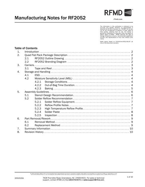
Table of Contents<br />
1. Introduction . . . . . . . . . . . . . . . . . . . . . . . . . . . . . . . . . . . . . . . . . . . . . . . . . . . . . . . . . . . . . . . . . 2<br />
2. Quad Flat Pack Package Description . . . . . . . . . . . . . . . . . . . . . . . . . . . . . . . . . . . . . . . . . . . . . 2<br />
2.1 <strong><strong>RF</strong>2052</strong> Outline Drawing . . . . . . . . . . . . . . . . . . . . . . . . . . . . . . . . . . . . . . . . . . . . . . . 2<br />
2.2 <strong><strong>RF</strong>2052</strong> Branding Diagram . . . . . . . . . . . . . . . . . . . . . . . . . . . . . . . . . . . . . . . . . . . . . 2<br />
3. Carriers. . . . . . . . . . . . . . . . . . . . . . . . . . . . . . . . . . . . . . . . . . . . . . . . . . . . . . . . . . . . . . . . . . . . . 3<br />
3.1 Tape and Reel . . . . . . . . . . . . . . . . . . . . . . . . . . . . . . . . . . . . . . . . . . . . . . . . . . . . . . . . 3<br />
4. Storage and Handling . . . . . . . . . . . . . . . . . . . . . . . . . . . . . . . . . . . . . . . . . . . . . . . . . . . . . . . . . 4<br />
4.1 ESD. . . . . . . . . . . . . . . . . . . . . . . . . . . . . . . . . . . . . . . . . . . . . . . . . . . . . . . . . . . . . . . . . 4<br />
4.2 Moisture Sensitivity Level (MSL) . . . . . . . . . . . . . . . . . . . . . . . . . . . . . . . . . . . . . . . . . 4<br />
4.2.1 Storage Conditions . . . . . . . . . . . . . . . . . . . . . . . . . . . . . . . . . . . . . . . . . . . . . 4<br />
4.2.2 Out-of-Bag Time Duration. . . . . . . . . . . . . . . . . . . . . . . . . . . . . . . . . . . . . . . . 4<br />
4.2.3 Baking . . . . . . . . . . . . . . . . . . . . . . . . . . . . . . . . . . . . . . . . . . . . . . . . . . . . . . . 5<br />
5. Assembly Guidelines . . . . . . . . . . . . . . . . . . . . . . . . . . . . . . . . . . . . . . . . . . . . . . . . . . . . . . . . . . 6<br />
5.1 Stencil Design Recommendation. . . . . . . . . . . . . . . . . . . . . . . . . . . . . . . . . . . . . . . . . 6<br />
5.2 Solder Reflow Recommendation . . . . . . . . . . . . . . . . . . . . . . . . . . . . . . . . . . . . . . . . . 7<br />
5.2.1 Solder Reflow Equipment. . . . . . . . . . . . . . . . . . . . . . . . . . . . . . . . . . . . . . . . 7<br />
5.2.2 Reflow Profile <strong>Notes</strong> . . . . . . . . . . . . . . . . . . . . . . . . . . . . . . . . . . . . . . . . . . . . 7<br />
5.2.3 High Temperature Reflow Profile. . . . . . . . . . . . . . . . . . . . . . . . . . . . . . . . . . 7<br />
5.2.4 Solder Paste . . . . . . . . . . . . . . . . . . . . . . . . . . . . . . . . . . . . . . . . . . . . . . . . . . 8<br />
5.2.5 Inspection . . . . . . . . . . . . . . . . . . . . . . . . . . . . . . . . . . . . . . . . . . . . . . . . . . . . 8<br />
6. Part Removal/Rework . . . . . . . . . . . . . . . . . . . . . . . . . . . . . . . . . . . . . . . . . . . . . . . . . . . . . . . . . 9<br />
6.1 Removal Method . . . . . . . . . . . . . . . . . . . . . . . . . . . . . . . . . . . . . . . . . . . . . . . . . . . . . . 9<br />
6.2 Replacement Method . . . . . . . . . . . . . . . . . . . . . . . . . . . . . . . . . . . . . . . . . . . . . . . . . . 9<br />
7. Summary In<strong>for</strong>mation . . . . . . . . . . . . . . . . . . . . . . . . . . . . . . . . . . . . . . . . . . . . . . . . . . . . . . . . 10<br />
8. Revision History . . . . . . . . . . . . . . . . . . . . . . . . . . . . . . . . . . . . . . . . . . . . . . . . . . . . . . . . . . . . . 10<br />
2052020A<br />
<strong>RF</strong> MICRO DEVICES®, <strong>RF</strong>MD®, Optimum Technology Matching®, Enabling Wireless Connectivity, PowerStar®, POLARIS TOTAL RADIO and UltimateBlue are trademarks of <strong>RF</strong>MD, LLC. BLUETOOTH is a trademark<br />
owned by Bluetooth SIG, Inc., U.S.A. and licensed <strong>for</strong> use by <strong>RF</strong>MD. All other trade names, trademarks and registered trademarks are the property of their respective owners. ©2006, <strong>RF</strong> <strong>Micro</strong> <strong>Devices</strong>, Inc.<br />
7628 Thorndike Road, Greensboro, NC 27409-9421 · For sales or technical<br />
support, contact <strong>RF</strong>MD at (+1) 336-678-5570 or sales-support@rfmd.com.<br />
1 of 10
<strong><strong>RF</strong>2052</strong> <strong>Manufacturing</strong> <strong>Notes</strong><br />
1. Introduction<br />
This manufacturing note is intended <strong>for</strong> surface mount technology (SMT) manufacturing engineers who are currently using the<br />
<strong><strong>RF</strong>2052</strong> <strong>for</strong> prototype or production manufacturing. The in<strong>for</strong>mation provided in this document is meant to assist customers<br />
with the set-up and characterization of their products.<br />
2. Quad Flat Pack Package Description<br />
A quad flat pack - no leads (QFN) package consists of a lead frame base containing one or more die attached to a ground pad<br />
provided in the center of the package. The leads and ground pad are all made from the same Cu material, using an etch process<br />
that <strong>for</strong>ms the leads and ground pad in predetermined configurations and sizes. The assembled device is then coated<br />
with a protective plastic overmold material, which provides mechanical and environmental protection to the package.<br />
The input and output terminations <strong>for</strong> the <strong><strong>RF</strong>2052</strong> are in the <strong>for</strong>m of Cu leads that are <strong>for</strong>med around the periphery of the<br />
package and are coated with a surface finish (8-20 μm thickness).<br />
2.1 <strong><strong>RF</strong>2052</strong> Outline Drawing<br />
2.2 <strong><strong>RF</strong>2052</strong> Branding Diagram<br />
If included on branding diagram, YY indicates year; WW indicates work week; and Trace Code<br />
is a sequential number assigned at device assembly.<br />
2052020A<br />
7628 Thorndike Road, Greensboro, NC 27409-9421 · For sales or technical<br />
support, contact <strong>RF</strong>MD at (+1) 336-678-5570 or sales-support@rfmd.com.<br />
2 of 10
<strong><strong>RF</strong>2052</strong> <strong>Manufacturing</strong> <strong>Notes</strong><br />
3. Carriers<br />
3.1 Tape and Reel<br />
Carrier tape basic dimensions are based on EIA 481. The pocket is designed to hold the part <strong>for</strong> shipping and loading<br />
onto SMT manufacturing equipment, while protecting the body and the solder terminals from damaging stresses. The<br />
individual pocket design can vary from vendor to vendor, but width and pitch will be consistent.<br />
Carrier tape is wound or placed onto a shipping reel either 330 mm (13 inches) in diameter or 178 mm (7 inches) in<br />
diameter. The center hub design is large enough to ensure the radius <strong>for</strong>med by the carrier tape around it does not put<br />
unnecessary stress on the parts.<br />
Prior to shipping, moisture sensitive parts (MSL level 2a-5a) are baked and placed into the pockets of the carrier tape. A<br />
cover tape is sealed over the top of the entire length of the carrier tape. The reel is sealed in a moisture barrier ESD bag<br />
with the appropriate units of desiccant and a humidity indicator card, which is placed in a cardboard shipping box. It is<br />
important to note that unused moisture sensitive parts need to be resealed in the moisture barrier bag. If the reels<br />
exceed the exposure limit and need to be rebaked, most carrier tape and shipping reels are not rated as bakeable at<br />
125°C. If baking is required, devices may be baked according to section 4, table 4-1, of Joint Industry Standard IPC/<br />
JEDEC J-STD-033.<br />
Table 1 provides useful in<strong>for</strong>mation <strong>for</strong> carrier tape and reels used <strong>for</strong> shipping the devices described in this document.<br />
Table 1. Tape and Reel<br />
<strong>RF</strong>MD Part Number<br />
Reel<br />
Diameter<br />
Inch (mm)<br />
Hub<br />
Diameter<br />
Inch (mm)<br />
Width<br />
(mm)<br />
Pocket Pitch<br />
(mm)<br />
Feed<br />
Units per<br />
Reel<br />
<strong><strong>RF</strong>2052</strong>TR13 13 (330) 4 (102) 12 8 Single 2500<br />
<strong><strong>RF</strong>2052</strong>TR7 7 (178) 2.4 (61) 12 8 Single 750<br />
Unless otherwise specified, all dimension tolerances per EIA-481.<br />
Pin 1<br />
Location<br />
Top View<br />
Sprocket holes toward<br />
rear of reel<br />
Part Number<br />
YYWW<br />
Trace Code<br />
Part Number<br />
YYWW<br />
Trace Code<br />
Part Number<br />
YYWW<br />
Trace Code<br />
Part Number<br />
YYWW<br />
Trace Code<br />
Direction of Feed<br />
Figure 1. 5mm x 5mm (Carrier Tape Drawing with Part Orientation)<br />
2052020A<br />
7628 Thorndike Road, Greensboro, NC 27409-9421 · For sales or technical<br />
support, contact <strong>RF</strong>MD at (+1) 336-678-5570 or sales-support@rfmd.com.<br />
3 of 10
<strong><strong>RF</strong>2052</strong> <strong>Manufacturing</strong> <strong>Notes</strong><br />
4. Storage and Handling<br />
4.1 ESD<br />
Electrostatic discharge occurs naturally in the environment. With the increase in voltage potential, the outlets of neutralization<br />
or discharge will be sought. If the acquired discharge route is through a semiconductor device, destructive damage<br />
will result.<br />
ESD countermeasure methods should be developed and used to control potential ESD damage during handling in a factory<br />
environment at each manufacturing site.<br />
<strong><strong>RF</strong>2052</strong> is considered ESD sensitive and needs to be handled accordingly.<br />
<strong>RF</strong>MD recommends utilizing standard ESD precautions (see Reference Documents) when handling these devices.<br />
Reference Documents:<br />
1. JEDEC Standard JESD625-A, “Requirements <strong>for</strong> Handling Electrostatic-Discharge-Sensitive (ESDS) <strong>Devices</strong>.”<br />
2. ANSI/ESD S20.20, “Protection of Electrical and Electronic Parts, Assemblies and Equipment (Excluding Electrically Initiated<br />
Explosive <strong>Devices</strong>).”<br />
NOTE: The <strong><strong>RF</strong>2052</strong> ESD level is documented in the product qualification report that is available from <strong>RF</strong>MD.<br />
4.2 Moisture Sensitivity Level (MSL)<br />
<strong><strong>RF</strong>2052</strong> is a moisture sensitive part. <strong>RF</strong>MD marks the MSL level and peak reflow temperature <strong>for</strong> the device on each<br />
shipping bag and reel label. It is important that the parts are handled according to the conditions indicated.<br />
The handling, baking, and floor life requirements of moisture sensitive parts are discussed in section 4, section 5, and<br />
section 6 of Joint Industry Standard IPC/JEDEC J-STD-033. <strong>RF</strong>MD qualifies the MSL of each device in accordance with the<br />
reflow profile found in the Joint Industry Standard IPC/JEDEC J-STD-020.<br />
If moisture sensitive parts are not applied to a board within the maximum “out-of-bag” or floor life exposure time, then<br />
the parts must be baked according to section 4, table 4-1 of Joint Industry Standard IPC/JEDEC J-STD-033 to remove any<br />
moisture absorbed into the part. The floor life exposures can be extended by storing open component reels in nitrogen or<br />
dry air storage cabinets when not in use.<br />
Prior to any rework it is highly recommended that the PCB be baked in a calibrated oven/chamber <strong>for</strong> 24 hours at 125°C<br />
to remove moisture from assembly. The pre-bake will prevent damage to any components due to moisture vapor pressures<br />
caused during rework. See section 7 <strong>for</strong> additional details on rework procedures.<br />
Reference Documents:<br />
1. IPC/JEDEC J-STD-033, “Joint Industry Standard Handling, Packing, Shipping, and Use of Moisture/Reflow Sensitive<br />
Surface Mount <strong>Devices</strong>.”<br />
2. IPC/JEDEC J-STD-020, “Joint Industry Standard Moisture/Reflow Sensitivity Classification <strong>for</strong> NonHermetic Solid State<br />
Surface Mount <strong>Devices</strong>.”<br />
NOTE: The <strong><strong>RF</strong>2052</strong> MSL level is documented in the product qualification report that is available from <strong>RF</strong>MD.<br />
4.2.1 Storage Conditions<br />
Packages described in this document must be stored in sealed moisture barrier, anti-static bags. Shelf life in a<br />
sealed moisture barrier bag is 12 months at < 40°C and < 90% relative humidity (RH).<br />
4.2.2 Out-of-Bag Time Duration<br />
After unpacking, the device must be soldered to the PCB within the time listed on the moisture barrier bag label.<br />
If the parts are provided in a tape and reel configuration, reels that have not been opened are considered<br />
unused. If multiple reels are provided per bag, the reels should be removed one at a time and the remaining reels<br />
resealed. Any unused parts may be returned to the shelf and stored <strong>for</strong> later use, but the out-of-bag exposure<br />
time allowed <strong>for</strong> the parts will have been reduced by the time previously out of the bag.<br />
2052020A<br />
7628 Thorndike Road, Greensboro, NC 27409-9421 · For sales or technical<br />
support, contact <strong>RF</strong>MD at (+1) 336-678-5570 or sales-support@rfmd.com.<br />
4 of 10
<strong><strong>RF</strong>2052</strong> <strong>Manufacturing</strong> <strong>Notes</strong><br />
4.2.3 Baking<br />
It is not necessary to bake the parts if both above conditions have been satisfied.<br />
Baking must be done if at least one of the conditions described in sections 4.2.1 or 4.2.2 has not been satisfied.<br />
Refer to JEDEC J-STD-033 <strong>for</strong> baking requirements.<br />
Caution: Tape and reel materials typically must be baked <strong>for</strong> a longer time at lower temperatures. If baking is<br />
required, devices may be baked according to section 4, table 4-1, of Joint Industry Standard IPC/JEDEC J-STD-<br />
033.<br />
2052020A<br />
7628 Thorndike Road, Greensboro, NC 27409-9421 · For sales or technical<br />
support, contact <strong>RF</strong>MD at (+1) 336-678-5570 or sales-support@rfmd.com.<br />
5 of 10
<strong><strong>RF</strong>2052</strong> <strong>Manufacturing</strong> <strong>Notes</strong><br />
5. Assembly Guidelines<br />
5.1 Stencil Design Recommendation<br />
The PCB pad pattern designs suggested in the component data sheets are important to successful part mounting and<br />
reliability. In addition to the PCB layout, printed solder paste deposits are critical in achieving a reliable solder joint. The<br />
stencil recommendation below is based on the PCB footprint design found in the product data sheet. Since surface<br />
mount processes vary from company to company, careful process development is recommended. The following provides<br />
some guidelines <strong>for</strong> stencil designs based on <strong>RF</strong>MD’s experience in surface mounting these packages.<br />
The stencil apertures are typically designed to match the PCB pad size and are decreased <strong>for</strong> an overall 10%-20% reduction<br />
in paste area <strong>for</strong> each pad. The thermal pad stencil aperture should be designed to achieve component standoff<br />
height of 2-3mils. This has yielded good solder joint results based on volumes assembled during the product introduction<br />
phase. To aid in the reduction of solder voids and out-gassing, smaller multiple openings in the stencil can be used<br />
instead of one large opening on the thermal pad region. However, eliminating voids completely may not be possible due<br />
to the presence of thermal vias and large component pads. Solder joint acceptability should be based on “Bottom Only<br />
Terminations” in IPC-A-610.<br />
Critical parameters to consider <strong>for</strong> successful solder paste application include the following.<br />
• Accurate registration of the stencil to the PCB during printing.<br />
• Good release of the stencil from the PCB after paste is applied. This is improved with laser- cut trapezoidal openings.<br />
• Proper storage and handling of solder paste based on solder paste vendor guidelines.<br />
• Frequent cleaning of the solder paste stencil to remove residual solder paste.<br />
• Stencil material recommendations: 5 mil (0.127 mm) thick stainless steel and laser-cut stencils with trapezoidal openings<br />
to promote easy release of solder paste.<br />
• NOTE: For half-etch lead packages, the stencil apertures <strong>for</strong> the peripheral leads may be decreased due to less solderable<br />
area of the leads.<br />
0.50 (mm) Typ.<br />
A = 0.58 x 0.25 (mm) Typ.<br />
B = 0.25 x 0.58 (mm) Typ.<br />
C = 3.15 (mm) Sq.<br />
3.50 (mm) Typ.<br />
Pin 32<br />
Pin 1<br />
0.50 (mm) Typ.<br />
A<br />
A<br />
A<br />
B<br />
B B B B B B B<br />
A<br />
A<br />
A<br />
Pin 24<br />
1.75 (mm)<br />
A<br />
A<br />
C<br />
A<br />
A<br />
3.50 (mm)<br />
Typ.<br />
A<br />
A<br />
A<br />
A<br />
0.55 (mm) Typ.<br />
0.55 (mm) Typ.<br />
A<br />
A<br />
B B B B B B B B<br />
Pin 16<br />
1.75 (mm)<br />
Figure 2. Stencil Recommendation<br />
2052020A<br />
7628 Thorndike Road, Greensboro, NC 27409-9421 · For sales or technical<br />
support, contact <strong>RF</strong>MD at (+1) 336-678-5570 or sales-support@rfmd.com.<br />
6 of 10
<strong><strong>RF</strong>2052</strong> <strong>Manufacturing</strong> <strong>Notes</strong><br />
5.2 Solder Reflow Recommendation<br />
This in<strong>for</strong>mation is provided as a guideline to facilitate the successful implementation of a surface mount process customized<br />
to the user’s requirements.<br />
5.2.1 Solder Reflow Equipment<br />
Recommendations provided are based on a 100% convection reflow oven capable of maintaining temperatures<br />
specified in Joint Industry Standard IPC/JEDEC J-STD-020.<br />
5.2.2 Reflow Profile <strong>Notes</strong><br />
An optimized reflow profile depends on several factors such as the solder paste, board density, and type of reflow<br />
equipment used. Additional reflow in<strong>for</strong>mation can be obtained from solder paste vendor data sheets.<br />
It is recommended that any reflow profile be characterized with a fully populated production PCB. Thermocouples<br />
can be used to record temperatures across the surface and any sensitive components on the PCB. Ensure that a<br />
thermocouple is placed in contact with the top surface of any moisture sensitive component to ensure maximum<br />
temperature is not exceeded.<br />
5.2.3 High Temperature Reflow Profile<br />
Maximum reflow temperature is 260°C. The temperature used to classify the MSL level appears on the MSL<br />
label on each shipping bag. <strong>RF</strong>MD uses reflow profiles in accordance with IPC/JEDEC J-STD-020 <strong>for</strong> qualification<br />
with the exception of the maximum reflow temperature of 260°C.<br />
Ramp-up rate<br />
3°C/second max.<br />
Preheat temperature 175 (±25)°C<br />
180 seconds max.<br />
Temperature maintained above 217°C 60-150 seconds<br />
Time within 5°C of actual peak temperature 20-40 seconds<br />
Peak temperature range<br />
260 +0/-5°C<br />
Ramp-down rate<br />
6°C/second max.<br />
Time 25°C to peak temperature<br />
8 minutes max.<br />
Maximum number of reflow cycles < 3<br />
Pre-baking requirements<br />
Refer to JEDEC J-STD-033 if original device package is<br />
unsealed.<br />
Maximum reflow temperature 260°C<br />
Time within 5°C of actual Peak Temp<br />
20-40 seconds<br />
Peak Temp 260 +0/-5°C<br />
Ramp-up rate 3°C/sec max<br />
to 175±25°C<br />
Critical Zone<br />
<strong>RF</strong>MD Reflow Profile<br />
(Not to scale)<br />
Preheat Temp<br />
Temperature °C<br />
200°C Max<br />
Preheat Temp<br />
150°C Min<br />
Preheat Time (min to max)<br />
60-150 secs<br />
above 217°C<br />
Ramp-down rate<br />
6°C/sec max<br />
60-180 seconds<br />
25<br />
0<br />
Time 25°C to Peak Temp<br />
8 minutes max.<br />
Time<br />
Note: All temperature refer to topside of the package, measured on the package body surface. The JEDEC reflow profile is not to scale.<br />
IPC-020b-5-1<br />
Figure 3. Typical High Temperature Reflow Profile<br />
2052020A<br />
7628 Thorndike Road, Greensboro, NC 27409-9421 · For sales or technical<br />
support, contact <strong>RF</strong>MD at (+1) 336-678-5570 or sales-support@rfmd.com.<br />
7 of 10
<strong><strong>RF</strong>2052</strong> <strong>Manufacturing</strong> <strong>Notes</strong><br />
5.2.4 Solder Paste<br />
Solder paste used <strong>for</strong> the <strong>RF</strong>MD high temperature reflow qualification.<br />
Solder paste<br />
Multicore 96SCAGS89 (CR39)<br />
Alloy type<br />
Sn95.5/Ag3.8/Cu0.7<br />
Metal content 88.5%<br />
Solder particle size 45 μm to 20 μm<br />
A no-clean, type 3 solder paste is recommended since it is difficult to completely clean residues under low profile<br />
components after they have been soldered to the PCB. Eliminating residues reduces the possibility of solder<br />
bridging between non-connected pads. This condition is affected by time, temperature, and humidity and will not<br />
be visible during initial inspection after reflow.<br />
5.2.5 Inspection<br />
It is recommended that x-ray inspection be per<strong>for</strong>med <strong>for</strong> any solder joints that are not visible after assembly. The<br />
following analysis and inspection criteria have been shown to result in component attachments that pass all<br />
<strong>RF</strong>MD package qualification procedures:<br />
• Evaluate solder paste printing process. Measure print height, and paste slump.<br />
• Per<strong>for</strong>m visual inspection <strong>for</strong> excess solder on terminal pads be<strong>for</strong>e and after reflow.<br />
• Per<strong>for</strong>m x-ray to inspect <strong>for</strong> proper alignment, solder voids, solder balls, and solder bridging after reflow.<br />
• Check <strong>for</strong> a minimum of 80% solder coverage on pad.<br />
• There should be complete solder coverage on ground pads directly under die locations in component.<br />
• Inspect <strong>for</strong> solder bridging or splatter between I/O pads.<br />
2052020A<br />
7628 Thorndike Road, Greensboro, NC 27409-9421 · For sales or technical<br />
support, contact <strong>RF</strong>MD at (+1) 336-678-5570 or sales-support@rfmd.com.<br />
8 of 10
<strong><strong>RF</strong>2052</strong> <strong>Manufacturing</strong> <strong>Notes</strong><br />
6. Part Removal/Rework<br />
Prior to any rework it is highly recommended that the PCB be baked in a calibrated oven/chamber <strong>for</strong> 24 hours at 125°C<br />
to remove moisture from the assembly. The pre-bake will prevent damage to any components due to moisture vapor pressures<br />
caused during rework.<br />
6.1 Removal Method<br />
• It is recommended that a heat controlled rework station be used.<br />
• The ideal reflow profile <strong>for</strong> part removal should match the one used <strong>for</strong> initial part attachment. Because the rework<br />
area is small, the duration of time the heat is applied after the solder reflows completely can be less than the original<br />
reflow profile as long as the preheat and soak times are the same as the original profile.<br />
• The board should be heated from the bottom side using convective heaters to reduce thermal shock to the PCB.<br />
• Hot air/gas tools fitted with special nozzles should be used to direct the heating to the component area being replaced<br />
and to avoid the heating of adjacent parts during rework.<br />
• Excessive airflow should be avoided to prevent skew and disruption of adjacent components.<br />
• A vacuum lift tool can be used to remove the component once all solder joints have reflowed. Special care must be<br />
taken to ensure total reflow and to prevent pad liftoff.<br />
• Heat guns and soldering irons are not recommended <strong>for</strong> removal or rework.<br />
6.2 Replacement Method<br />
• Be<strong>for</strong>e replacing the component, the PCB land should be properly cleaned.<br />
• Residual solder must be removed and the lands cleaned. The type of paste used in the original assembly determines<br />
the cleaning method.<br />
• The preferred method <strong>for</strong> applying solder paste is a mini stencil that has the same thickness, aperture size and shape<br />
as the one used during initial assembly. The stencil is aligned to the pads and paste applied with a small metal squeegee<br />
blade. If space does not allow a mini stencil, paste can be dispensed directly to the PCB lands, however some process<br />
development is required to determine an appropriate amount of solder paste to ensure successful solder<br />
attachment.<br />
• A no-clean, type 3 solder paste is recommended to prevent trapping residues under the component that cannot be<br />
cleaned after assembly.<br />
• Placement of component can be done using magnification to check alignment. Placement equipment should have the<br />
ability to adjust X, Y, and Z coordinates and provide consistent alignment to pad and component placement pressure.<br />
Small packages will also have some self-centering characteristics due to small mass and will align themselves during<br />
reflow.<br />
• The reflow profile used during the original assembly should be used to attach the new component. If different equipment<br />
or paste is used, the reflow profile will need to be optimized again.<br />
2052020A<br />
7628 Thorndike Road, Greensboro, NC 27409-9421 · For sales or technical<br />
support, contact <strong>RF</strong>MD at (+1) 336-678-5570 or sales-support@rfmd.com.<br />
9 of 10
<strong><strong>RF</strong>2052</strong> <strong>Manufacturing</strong> <strong>Notes</strong><br />
7. Summary In<strong>for</strong>mation<br />
Package size<br />
Package thickness<br />
Package surface finish<br />
Handling requirements<br />
Shelf-life in bag<br />
RoHS status<br />
5mm x 5mm<br />
.95mm (maximum)<br />
8-20 μm thickness<br />
ESD sensitive; moisture sensitive (Ref. JESD625-A; IPC/JEDEC J-STD-033).<br />
12 months at < 40°C and < 90% relative humidity<br />
RoHS compliant<br />
8. Revision History<br />
Revision Date Description<br />
1 06/08 Preliminary release.<br />
A 01/09 Production release.<br />
2052020A<br />
7628 Thorndike Road, Greensboro, NC 27409-9421 · For sales or technical<br />
support, contact <strong>RF</strong>MD at (+1) 336-678-5570 or sales-support@rfmd.com.<br />
10 of 10