µ δ ÏA δc - MITCalc
µ δ ÏA δc - MITCalc
µ δ ÏA δc - MITCalc

Create successful ePaper yourself
Turn your PDF publications into a flip-book with our unique Google optimized e-Paper software.
i<br />
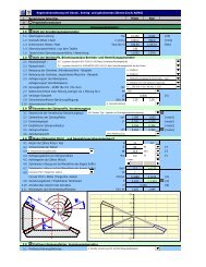
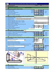
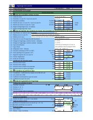
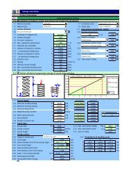
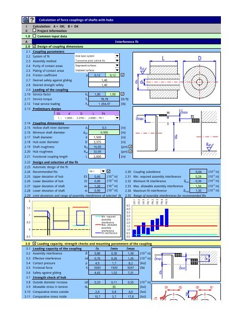
Název Calculation výpočtu of force couplings of shafts with hubs<br />
Calculation: A = OK; B = OK<br />
ii Informace Project information<br />
o projektu<br />
1.0<br />
A<br />
2.0<br />
2.1<br />
2.2<br />
2.3<br />
2.4<br />
2.5<br />
2.6 Friction coefficient<br />
µ 0,12 0,12<br />
2.7<br />
2.8<br />
2.9<br />
2.10 Service factor<br />
K S 1,00 1,00<br />
2.11 Service torque<br />
T S<br />
2.12 Total service loading<br />
F S<br />
2.13<br />
2.14<br />
2.15 Hollow shaft inner diameter<br />
d 0<br />
2.16 Minimum shaft diameter<br />
d min<br />
2.17 Shaft diameter<br />
d<br />
2.18 Hub outer diameter D 3,375<br />
2.19 Shaft roughness<br />
R aS<br />
2.20 Hub roughness<br />
R aH<br />
2.21 Functional coupling length<br />
L<br />
2.22<br />
2.23<br />
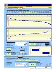
2.24 Recommended fits<br />
FN 1<br />
2.30 Coupling subsidence<br />
0,04 [10 -3 in]<br />
2.25 Upper deviation of hub ES 0,60 [10 -3 in] 2.31 Min. required assembly interference 0,28 [10 -3 in]<br />
2.26 Lower deviation of hub<br />
EI 0,00 [10 -3 in] 2.32 Minimum fit interference<br />
δ min 0,30 [10 -3 in]<br />
2.27 Upper deviation of shaft<br />
es 1,30 [10 -3 in] 2.33 Max. allowable assembly interference 1,56 [10 -3 in]<br />
2.28 Lower deviation of shaft<br />
ei 0,90 [10 -3 in] 2.34 Maximum fit interference δ max 1,30 [10 -3 in]<br />
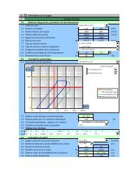
2.29 Limit deviations and range of assembly interference of selected fit 2.35 Range of assembly interferences for recommended fits<br />
2<br />
1,5<br />
1<br />
0,5<br />
0<br />
-0,5<br />
3.0<br />
3.1 Loading capacity of the coupling dc<br />
3.2 Assembly interference δ 0,80<br />
3.3 Effective interference<br />
∆d<br />
3.4 Contact pressure<br />
p<br />
3.5 Frictional force<br />
F f<br />
3.6<br />
3.7<br />
3.8 Outside diameter increase<br />
∆D<br />
3.9 Allowable stress in tension σ A<br />
30<br />
3.10<br />
3.11<br />
Common input data<br />
Design of coupling dimensions<br />
Coupling parameters<br />
System of fit<br />
Assembly method<br />
Purity of contact areas<br />
Plating of contact areas<br />
Desired safety against gliding<br />
Desired strength safety<br />
Loading of the coupling<br />
Preliminary design<br />
Coupling dimensions<br />
Design and selection of the fit<br />
Automatic design of the fit<br />
Comparative stress outside<br />
16,00<br />
32,00<br />
2,000<br />
4,9<br />
5583<br />
2,4<br />
Comparative stress inside 10,7<br />
1,40<br />
78,78<br />
ID. d D L Fit<br />
1,500<br />
1,52<br />
0,11<br />
0,8<br />
3,7<br />
[lb ft]<br />
[in]<br />
[in]<br />
[in]<br />
[in]<br />
[µin]<br />
[µin]<br />
Loading capacity, strength checks and mounting parameters of the coupling<br />
Safety against gliding<br />
Strength check of hub<br />
Hole basis system<br />
Transverse press (shrink fit)<br />
Degreased surfaces<br />
Unplated surfaces<br />
1. | 1.5000 | 3.3750 | 2.0000 | FN 1<br />
0,76<br />
4,42<br />
0,33<br />
1,40<br />
1 264,47<br />
0,5<br />
0,905<br />
Min. required<br />
assembly<br />
interference<br />
Max. allowable<br />
assembly<br />
interference<br />
Fit interference<br />
dmin<br />
0,30<br />
0,26<br />
1,7<br />
1920<br />
Interference fit<br />
[lb]<br />
[in]<br />
4,5<br />
4,0<br />
3,5<br />
3,0<br />
2,5<br />
2,0<br />
1,5<br />
1,0<br />
0,5<br />
0,0<br />
dmax<br />
1,30<br />
1,26<br />
8,2<br />
9247<br />
7,31<br />
0,55<br />
[ksi]<br />
[lb]<br />
[10 -3 in]<br />
[ksi]<br />
4,0 [ksi]<br />
17,8<br />
LN 1<br />
LN 2<br />
LN 3<br />
[10 -3 in]<br />
[10 -3 in]<br />
[ksi]<br />
FN 1<br />
FN 2<br />
FN 3<br />
FN 4<br />
FN 5
3.12<br />
3.13<br />
3.14<br />
Safety<br />
Strength check of shaft<br />
Inside diameter decrease<br />
∆d 0<br />
2,80<br />
0,18<br />
8,14<br />
0,06<br />
1,69<br />
0,30 [10 -3 in]<br />
3.15 Allowable stress in tension σ A<br />
34,8<br />
[ksi]<br />
3.16<br />
3.17<br />
3.18<br />
Comparative stress outside<br />
Comparative stress inside<br />
Safety<br />
5,7<br />
11,1<br />
3,13<br />
1,9<br />
3,8<br />
9,11<br />
9,4<br />
18,4<br />
1,89<br />
[ksi]<br />
[ksi]<br />
3.19 Check of coupling for deformation<br />
3.23 Check of shaft for torsion<br />
3.20 Allowable contact pressure p A 13,5 [ksi] 3.24 Allowable stress in shear<br />
τ A 24,4 [ksi]<br />
3.21 Max. contact pressure<br />
p max 8,2 [ksi] 3.25 Comparative stress<br />
τ 2,9 [ksi]<br />
3.22 Safety<br />
1,65<br />
3.26 Safety<br />
8,45<br />
3.27<br />
3.28<br />
Mounting parameters of the coupling<br />
Transverse press (shrink fit)<br />
3.41 Longitudinal press (force fit)<br />
3.29 Fit With maximum interference<br />
3.42 Fit<br />
With maximum interference<br />
3.30 Assembly clearance<br />
c 0,0015 [in] 3.43 Necessary pressing force<br />
F p 0 [lb]<br />
3.31<br />
3.32<br />
Heat expansion coefficient :<br />
- Hub material (warming)<br />
α H 5 [10 -6 /°F]<br />
3.33 - Shaft material (warming) α S 6,5 [10 -6 /°F]<br />
3.34 - Shaft material (cooling)<br />
α Sc 5 [10 -6 /°F]<br />
3.35 Determination of necessary hub heating temperature<br />
3.36 Shaft temperature<br />
T S 68,0 [°F]<br />
3.37 Necessary hub temperature<br />
T H 441,3 [°F]<br />
3.38 Determination of necessary shaft cooling temperature<br />
3.39 Hub temperature<br />
T H 200,0 [°F]<br />
3.40 Necessary shaft temperature T S -173,3 [°F]<br />
4.0<br />
4.1<br />
Check of the coupling strained by additional load<br />
Loading of the coupling<br />
4.2 Additional radial force<br />
F R 500,00 [lb]<br />
4.3 Additional bending moment<br />
M 20,00 [lb ft]<br />
4.4 Amplitude of the pressure ∆p 0,26<br />
[ksi]<br />
4.5<br />
4.6<br />
Check of the coupling<br />
Medium contact pressure<br />
p<br />
dc<br />
4,9<br />
dmin<br />
1,7<br />
dmax<br />
8,2 [ksi]<br />
4.7 Max. allowable contact pressure p maxA<br />
4.8 Maximum contact pressure p max<br />
4.9 Safety<br />
13,8<br />
5,2 2,0 8,4<br />
2,66 7,06 1,64<br />
[ksi]<br />
[ksi]<br />
4.10 Min. allowable contact pressure p minA<br />
0,4<br />
[ksi]<br />
4.11 Minimum contact pressure<br />
p min 4,7 1,4 7,9 [ksi]<br />
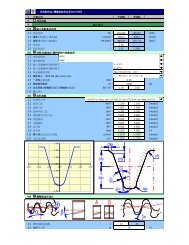
5.0 Check of the coupling at specific working temperature<br />
5.1 Service temperature<br />
T 300,0 [°F]<br />
5.2 Properties of the material<br />
Shaft<br />
Hub<br />
68 °F 300 °F 68 °F 300 °F<br />
5.3 Modulus of elasticity in tension E 30500 28530,0 24700 22790,0 [ksi]<br />
5.4 Heat expansion coefficient<br />
α 6,5 6,90 5 5,50 [10 -6 /°F]<br />
5.5 Poisson number<br />
ν 0,3 0,30 0,28 0,28<br />
5.6 Allowable stress in tension σ A 34,8 29,6 30 28,5 [ksi]<br />
5.7<br />
5.8<br />
Loading capacity of the coupling<br />
Assembly interference<br />
δ<br />
dc<br />
0,80<br />
dmin<br />
0,30<br />
dmax<br />
1,30 [10 -3 in]<br />
5.9 Effective interference<br />
∆d 0,76 0,26 1,26 [10 -3 in]<br />
5.10 Service interference<br />
∆d T 1,25 0,75 1,75 [10 -3 in]<br />
5.11 Contact pressure p T 7,5 4,5 10,5 [ksi]<br />
5.12 Frictional force F fT 8480 5086 11875 [lb]<br />
5.13<br />
5.14<br />
Safety against gliding<br />
6,71 4,02 9,39<br />
Strength check of hub<br />
5.15 Outside diameter increase ∆D T 4,85 4,63 5,07 [10 -3 in]<br />
5.16 Allowable stress in tension σ AT<br />
28,5<br />
[ksi]<br />
5.17<br />
5.18<br />
Comparative stress outside<br />
Comparative stress inside<br />
16,3<br />
3,7<br />
9,8<br />
2,2<br />
22,8<br />
5,2<br />
[ksi]<br />
[ksi]
5.19 Safety<br />
5.20<br />
5.21 Inside diameter decrease<br />
∆d 0T -0,50 -0,62<br />
5.22 Allowable stress in tension σ AT<br />
29,6<br />
5.23<br />
5.24<br />
5.25<br />
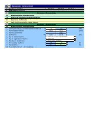
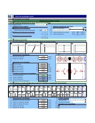
6.0<br />
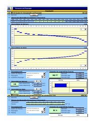
6.1 Desired parameters of the fit<br />
6.6<br />
6.3 Min. required assembly interference 7,10 [µm] Upper deviation<br />
ES 16 [µm]<br />
6.4 Max. allowable assembly interference 39,64 [µm] Lower deviation<br />
EI 0 [µm]<br />
6.5 Automatic search of the fit<br />
6.8 Shaft tolerance zone<br />
B<br />
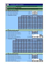
7.0<br />
7.1<br />
7.2<br />
7.3<br />
7.4 Friction coefficient<br />
µ 0,12 0,12<br />
7.5 Form factor<br />
K F<br />
7.6<br />
7.7<br />
7.8<br />
7.9 Service factor<br />
K S 1,00 1,00<br />
7.10 Service torque<br />
T S<br />
7.11 Total service loading<br />
F S<br />
7.12<br />
7.13 Hollow shaft inner diameter<br />
d 0<br />
7.14 Minimum shaft diameter<br />
d min<br />
7.15 Shaft diameter<br />
d<br />
7.16 Min. functional coupling length L min<br />
7.17 Functional coupling length<br />
L<br />
7.18<br />
7.20 Number of connecting bolts<br />
i<br />
7.21<br />
7.22 Mounting prestressing<br />
F 0<br />
7.23 Material of connecting bolt<br />
S Y<br />
7.24<br />
8.0<br />
Strength check of shaft<br />
Comparative stress outside<br />
Comparative stress inside<br />
Safety<br />
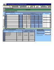
Extended fit selection according to ISO 286<br />
ID | Min. interfer. | Max. interfer.| Fit<br />
1. | 10 | 37 | H6/p5<br />
2. | 15 | 37 | H5/p5<br />
3. | 10 | 33 | H6/p4<br />
4. | 15 | 33 | H5/p4<br />
5. | 10 | 24 | H4/n4<br />
6. | 19 | 33 | H4/p4<br />
7. | 15 | 30 | H5/p3<br />
8. | 23 | 38 | H5/r3<br />
Design of coupling dimensions<br />
Coupling parameters<br />
Hub design<br />
Purity of contact areas<br />
Loading of the coupling<br />
Coupling dimensions<br />
Allowable mounting prestressing<br />
Min. recommended thread size<br />
1,75<br />
1,250<br />
1,250<br />
92,0<br />
1,224<br />
2300,0<br />
Loading capacity and strength checks of the coupling<br />
6.9<br />
6.10<br />
8.1 Loading capacity of the coupling<br />
8.13<br />
es 37 [µm]<br />
ei 26 [µm]<br />
10 [µm]<br />
37 [µm]<br />
8.2 Total clamping (normal) force N 9200,0 [lb] 8.14 Allowable contact pressure<br />
p A 13,5 [ksi]<br />
8.3 Contact pressure<br />
p 5,89 [ksi] 8.15 Max. contact pressure<br />
p max 7,9 [ksi]<br />
8.4 Frictional force<br />
F f 2601,2 [lb] 8.16 Safety<br />
1,72<br />
8.5 Total service loading<br />
F S 1515,9 [lb] 8.17<br />
8.6 Safety against gliding<br />
1,72<br />
8.18 Allowable stress in shear<br />
τ A 24,4 [ksi]<br />
8.7 Check of connecting bolt<br />
8.19 Comparative stress<br />
τ 5,1 [ksi]<br />
8.8 Yield point of the bolt material S Y 92 [ksi] 8.20 Safety<br />
4,82<br />
8.9 Thread size<br />
d 0,3125 [in] 8.21 Check of hollow shaft<br />
0,75<br />
0,5<br />
Mounting prestressing, design of connecting bolt<br />
4<br />
5/16<br />
2,92<br />
8,6 5,2<br />
16,9 10,1 23,6<br />
1,75 2,93<br />
Desired safety against gliding 1,70<br />
Desired strength safety<br />
1,70<br />
78,78<br />
1 515,91<br />
0,905<br />
2278,6 ~ 2326,5<br />
8.10 Tightening torque<br />
M 11,6 [lb ft] 8.22 Allowable stress in tension σ A 34,8 [ksi]<br />
8.11 Comparative stress in bolt core σ 66,9 [ksi] 8.23 Comparative stress<br />
σ 18,7 [ksi]<br />
8.12 Safety at yield point<br />
1,38<br />
8.24 Safety<br />
1,86<br />
p5<br />
Clamping connection<br />
[lb ft]<br />
[lb]<br />
[in]<br />
[in]<br />
[in]<br />
[in]<br />
[in]<br />
[lb]<br />
[lb]<br />
[ksi]<br />
-0,39<br />
12,0<br />
1,25<br />
Additions section<br />
[10 -3 in]<br />
6.2 Basic size<br />
38,10 [mm] 6.7 Hub tolerance zone<br />
A ... Separated hub<br />
Degreased surfaces<br />
SAE 5<br />
1,25<br />
[ksi]<br />
[ksi]<br />
[ksi]<br />
Selection of the fit<br />
H6<br />
Parameters of the selected fit<br />
H6/p5<br />
Upper deviation<br />
Lower deviation<br />
Minimum interference<br />
Maximum interference<br />
Check of coupling for deformation<br />
Check of shaft for torsion<br />
H<br />
p<br />
6<br />
5
9.0<br />
9.1<br />
Comparative table<br />
Interference fit<br />
9.10 Clamping connection<br />
9.2 Shaft diameter<br />
d 1,5 [in] 9.11 Shaft diameter<br />
d 1,25 [in]<br />
9.3 Functional coupling length<br />
L 2 [in] 9.12 Functional coupling length<br />
L 1,25 [in]<br />
9.4 Loading capacity of the coupling : 9.13 Loading capacity of the coupling :<br />
9.5 Min. frictional force<br />
F f 1919,7 [lb] 9.14 Frictional force<br />
F f 2601,2 [lb]<br />
9.6 Safety against gliding<br />
1,52<br />
9.15 Safety against gliding<br />
1,72<br />
9.7 Strength checks of the coupling :<br />
9.16 Strength checks of the coupling :<br />
9.8 Max. contact pressure<br />
p max 8,2 [ksi] 9.17 Max. contact pressure<br />
p max 7,9 [ksi]<br />
9.9 Safety<br />
1,69<br />
9.18 Safety<br />
1,72
![åæ¥å¸¶i ii ? 1.0 1.1 è¨ç®å®ä½1.2 å³éåçP [HP] 1.3 帶輪 ... - MITCalc](https://img.yumpu.com/36097619/1/190x245/aae-ai-ii-10-11-ecrara-1-2-12-aeacp-hp-13-ae-1-4-mitcalc.jpg?quality=85)