Red Tide USB650 Fiber Optic Spectrometer Installation and ...
Red Tide USB650 Fiber Optic Spectrometer Installation and ...
Red Tide USB650 Fiber Optic Spectrometer Installation and ...

Create successful ePaper yourself
Turn your PDF publications into a flip-book with our unique Google optimized e-Paper software.
1.<br />
<strong>Red</strong> <strong>Tide</strong><br />
<strong>USB650</strong> <strong>Fiber</strong> <strong>Optic</strong> <strong>Spectrometer</strong><br />
<strong>Installation</strong> <strong>and</strong> Operation Manual<br />
Document Number 170-00000-RT-02-1106<br />
Offices:<br />
Ocean <strong>Optic</strong>s, Inc. World Headquarters<br />
830 Douglas Ave., Dunedin, FL, USA 34698<br />
Phone 727.733.2447<br />
Fax 727.733.3962<br />
8 a.m.– 8 p.m. (Mon-Thu), 8 a.m.– 6 p.m. (Fri) EST<br />
E-mail: Info@Ocean<strong>Optic</strong>s.com (General sales inquiries)<br />
Orders@Ocean<strong>Optic</strong>s.com (Questions about orders)<br />
TechSupport@Ocean<strong>Optic</strong>s.com (Technical support)
Additional<br />
Offices:<br />
Ocean <strong>Optic</strong>s Asia<br />
137 Xianxia Road, Suite 1802, Changning District, Shanghai, PRC. 200051<br />
Phone 86.21.5206.8686<br />
Fax 86.21.5206.8686<br />
E-Mail Sun.Ling@Ocean<strong>Optic</strong>s.com<br />
Ocean <strong>Optic</strong>s B.V. (Europe)<br />
Geograaf 24, 6921 EW DUIVEN, The Netherl<strong>and</strong>s<br />
Phone 31-(0)26-3190500<br />
Fax 31-(0)26-3190505<br />
E-Mail Info@Ocean<strong>Optic</strong>sBV.com<br />
Copyright © 2001-2006 Ocean <strong>Optic</strong>s, Inc.<br />
All rights reserved. No part of this publication may be reproduced, stored in a retrieval system, or transmitted, by any means, electronic,<br />
mechanical, photocopying, recording, or otherwise, without written permission from Ocean <strong>Optic</strong>s, Inc.<br />
This manual is sold as part of an order <strong>and</strong> subject to the condition that it shall not, by way of trade or otherwise, be lent, re-sold, hired out or<br />
otherwise circulated without the prior consent of Ocean <strong>Optic</strong>s, Inc. in any form of binding or cover other than that in which it is published.<br />
Trademarks<br />
All products <strong>and</strong> services herein are the trademarks, service marks, registered trademarks or registered service marks of their respective owners.<br />
Limit of Liability<br />
Every effort has been made to make this manual as complete <strong>and</strong> as accurate as possible, but no warranty or fitness is implied. The information<br />
provided is on an “as is” basis. Ocean <strong>Optic</strong>s, Inc. shall have neither liability nor responsibility to any person or entity with respect to any loss or<br />
damages arising from the information contained in this manual.
Table of Contents<br />
About This Manual .......................................................................................................... iii<br />
Document Purpose <strong>and</strong> Intended Audience.............................................................................. iii<br />
Document Summary.................................................................................................................. iii<br />
Product-Related Documentation ............................................................................................... iii<br />
Upgrades......................................................................................................................... iv<br />
Chapter 1: Introduction ......................................................................1<br />
Product Overview ............................................................................................................ 1<br />
Features .......................................................................................................................... 2<br />
System Requirements ..................................................................................................... 2<br />
EEPROM Utilization .................................................................................................................. 2<br />
About SpectraSuite.................................................................................................................... 3<br />
Sampling System Overview....................................................................................................... 3<br />
How Sampling Works............................................................................................................ 3<br />
Modular Light Sources <strong>and</strong> Sampling Accessories .............................................................. 3<br />
Shipment Components.................................................................................................... 4<br />
Additional Equipment Needed......................................................................................... 4<br />
Other Accessories Available ........................................................................................... 5<br />
Chapter 2: Installing the <strong>Red</strong> <strong>Tide</strong> .....................................................7<br />
Overview ......................................................................................................................... 7<br />
<strong>Red</strong> <strong>Tide</strong> <strong>Installation</strong>........................................................................................................ 7<br />
Connect Spectroscopic Accessories ............................................................................... 8<br />
External Triggering Options............................................................................................. 8<br />
Chapter 3: Troubleshooting ...............................................................9<br />
Overview ......................................................................................................................... 9<br />
<strong>Red</strong> <strong>Tide</strong> Connected to Computer Prior to SpectraSuite <strong>Installation</strong> .............................. 9<br />
Windows Operating Systems .................................................................................................... 9<br />
Remove the Unknown Device from Windows Device Manager ........................................... 9<br />
Remove Improperly Installed Files........................................................................................ 10<br />
Mac Operating Systems ............................................................................................................ 10<br />
Linux Operating Systems .......................................................................................................... 11<br />
170-00000-RT-02-1106<br />
i
Table of Contents<br />
Appendix A: Calibrating the Wavelength of the <strong>Red</strong> <strong>Tide</strong>...............13<br />
Overview ......................................................................................................................... 13<br />
About Wavelength Calibration......................................................................................... 13<br />
Calibrating the <strong>Spectrometer</strong>........................................................................................... 14<br />
Preparing for Calibration............................................................................................................ 14<br />
Calibrating the Wavelength of the <strong>Spectrometer</strong> ...................................................................... 14<br />
Saving the New Calibration Coefficients: USB Mode ...................................................... 16<br />
Appendix B: External Triggering .......................................................17<br />
Overview ......................................................................................................................... 17<br />
Normal (Free Running).............................................................................................................. 17<br />
External Software Trigger.......................................................................................................... 17<br />
External Hardware Trigger ........................................................................................................ 17<br />
Appendix C: Specifications................................................................19<br />
Overview ......................................................................................................................... 19<br />
How the <strong>Red</strong> <strong>Tide</strong> Works ................................................................................................ 19<br />
<strong>Red</strong> <strong>Tide</strong> Components Table .................................................................................................... 20<br />
<strong>Red</strong> <strong>Tide</strong> Specifications................................................................................................... 21<br />
CCD Detector Specifications..................................................................................................... 21<br />
<strong>Red</strong> <strong>Tide</strong> <strong>Spectrometer</strong> ............................................................................................................. 21<br />
10-Pin Accessory Connector Pinout................................................................................ 23<br />
10-Pin Accessory Connector Pinout Diagram........................................................................... 23<br />
10-Pin Accessory Connector – Pin Definitions <strong>and</strong> Descriptions.............................................. 24<br />
Index.....................................................................................................25<br />
ii<br />
170-00000-RT-02-1106
About This Manual<br />
Document Purpose <strong>and</strong> Intended Audience<br />
This document provides the users of <strong>Red</strong> <strong>Tide</strong> <strong>Spectrometer</strong>s with instructions for setting up, calibrating<br />
<strong>and</strong> performing experiments with their spectrometer.<br />
Document Summary<br />
Chapter<br />
Chapter 1: Introduction<br />
Chapter 2: Installing the <strong>Red</strong> <strong>Tide</strong><br />
Chapter 3: Troubleshooting<br />
Appendix A: Calibrating the<br />
Wavelength of the <strong>Red</strong> <strong>Tide</strong><br />
Appendix B: External Triggering<br />
Appendix C: Specifications<br />
Description<br />
Contains descriptive information about the <strong>Red</strong> <strong>Tide</strong><br />
<strong>Spectrometer</strong> <strong>and</strong> how sampling works. It also provides a list<br />
of system requirements, interface options, <strong>and</strong> shipment<br />
components.<br />
Provides installation instructions.<br />
Contains recommended steps to isolate <strong>and</strong> correct common<br />
problems.<br />
Provides instructions for calibrating the <strong>Red</strong> <strong>Tide</strong><br />
<strong>Spectrometer</strong>.<br />
Contains information about external triggering for the <strong>Red</strong><br />
<strong>Tide</strong>.<br />
Contains technical specifications <strong>and</strong> connector pinouts for the<br />
<strong>Red</strong> <strong>Tide</strong> <strong>Spectrometer</strong>.<br />
Product-Related Documentation<br />
You can access documentation for Ocean <strong>Optic</strong>s products by visiting our website at<br />
http://www.oceanoptics.com. Select Technical → Operating Instructions, then choose the appropriate<br />
document from the available drop-down lists. Or, use the Search by Model Number field at the bottom<br />
of the web page.<br />
• Detailed instructions for SpectraSuite <strong>Spectrometer</strong> Operating Software are located at:<br />
http://www.oceanoptics.com/technical/SpectraSuite.pdf.<br />
• Detailed instructions for external triggering are located at:<br />
http://www.oceanoptics.com/technical/external triggering.pdf.<br />
• Detailed instructions for the Pasco Xplorer GLX are located at:<br />
ftp://ftp.pasco.com/manuals/English/PS/PS-2002/012-08950F/012-08950F.pdf.<br />
170-00000-RT-02-1106<br />
iii
About This Manual<br />
Engineering-level documentation is located on our website at Technical → Engineering Docs.<br />
You can also access operating instructions for Ocean <strong>Optic</strong>s products from the Software <strong>and</strong> Technical<br />
Resources CD that ships with the product.<br />
Upgrades<br />
Occasionally, you may find that you need Ocean <strong>Optic</strong>s to make a change or an upgrade to your system.<br />
To facilitate these changes, you must first contact Customer Support <strong>and</strong> obtain a Return Merch<strong>and</strong>ise<br />
Authorization (RMA) number. Please contact Ocean <strong>Optic</strong>s for specific instructions when returning a<br />
product.<br />
iv<br />
170-00000-RT-02-1106
Chapter 1<br />
Introduction<br />
Product Overview<br />
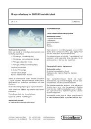
The Ocean <strong>Optic</strong>s <strong>Red</strong> <strong>Tide</strong> <strong>Spectrometer</strong> is a preconfigured, off-the-shelf spectrometer where all of the<br />
optical bench options such as grating, <strong>and</strong> entrance slit size are already selected. The red <strong>Tide</strong> can be used<br />
with various Ocean optics spectrometer accessories, light sources <strong>and</strong> sampling optics to create<br />
application-specific systems for various absorbance, reflection <strong>and</strong> emission applications.<br />
The <strong>Red</strong> <strong>Tide</strong> is low-cost <strong>and</strong> has a small footprint, making it ideal as a general purpose instrument for<br />
budget-conscious teaching <strong>and</strong> research labs. It has a wavelength range of 350–1000 nm <strong>and</strong> uses a<br />
detector with 650 active pixels; that’s 650 data points in one full spectrum, or one data point per<br />
nanometer.<br />
Data programmed into a memory chip on each <strong>Red</strong> <strong>Tide</strong> includes wavelength calibration coefficients,<br />
linearity coefficients, <strong>and</strong> the serial number unique to each spectrometer. Our spectrometer operating<br />
software simply reads these values from the spectrometer — a feature that enables hot swapping of<br />
spectrometers among computers.<br />
The <strong>Red</strong> <strong>Tide</strong> <strong>Spectrometer</strong> connects to a computer via the USB port. When connected through a USB 2.0<br />
or 1.1, the spectrometer draws power from the host computer, eliminating the need for an external power<br />
supply. The <strong>Red</strong> <strong>Tide</strong> also interfaces to Pasco’s Xplorer GLX, a unique combination of datalogger <strong>and</strong> lab<br />
analysis tool that eliminates the need for a computer.<br />
The <strong>Red</strong> <strong>Tide</strong>, like all USB devices, can be controlled by our SpectraSuite software, a completely<br />
modular, Java-based spectroscopy software platform that operates on Windows, Macintosh <strong>and</strong> Linux<br />
operating systems.<br />
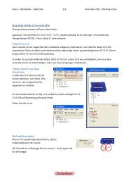
Ocean <strong>Optic</strong>s <strong>Red</strong> <strong>Tide</strong> <strong>Fiber</strong> <strong>Optic</strong> <strong>Spectrometer</strong><br />
170-00000-RT-02-1106 1
1: Introduction<br />
Features<br />
<br />
<br />
<br />
<br />
<br />
<br />
<br />
<br />
<br />
<br />
<br />
<br />
<br />
<br />
Sony ILX511 linear silicon CCD array detector<br />
Responsive from 350 to 1000 nm<br />
Sensitivity of up to 75 photons/count at 400 nm<br />
An optical resolution of ~2.0 (FWHM)<br />
Integration times from 3 ms to 65 seconds (15 seconds typical maximum)<br />
Embedded microcontroller allows programmatic control of all operating parameters<br />
EEPROM storage for<br />
• Wavelength Calibration Coefficients<br />
• Linearity Correction Coefficients<br />
• Other configuration parameters<br />
Low power consumption of only 450 mW<br />
12 bit, 1MHz A/D Converter<br />
3 triggering modes<br />
2 programmable strobe signals for triggering other devices<br />
24-pin connector for interfacing to external products<br />
Programmable for St<strong>and</strong>alone Operation<br />
CE Certification<br />
System Requirements<br />
You can use the <strong>Red</strong> <strong>Tide</strong>’s USB connectivity with any computer that meets the following requirements:<br />
• Operating system is one of the following:<br />
• Windows – 98/Me/2000/XP<br />
• Apple Macintosh – OS X version 10.0 or later<br />
• Linux – <strong>Red</strong> Hat 9 or later, Fedora (any version), Debian 3.1 (Sarge), <strong>and</strong> SUSE (9.0 or<br />
later)<br />
• Ocean <strong>Optic</strong>s’ SpectraSuite software application installed <strong>and</strong> configured for use with the <strong>Red</strong><br />
<strong>Tide</strong>.<br />
EEPROM Utilization<br />
An EEPROM memory chip in each <strong>Red</strong> <strong>Tide</strong> contains wavelength calibration coefficients, linearity<br />
coefficients, <strong>and</strong> a serial number unique to each individual spectrometer. The SpectraSuite software<br />
application reads these values directly from the spectrometer, enabling the ability to “hot-swap”<br />
spectrometers between computers without entering the spectrometer coefficients manually on each<br />
computer.<br />
2 170-00000-RT-02-1106
About SpectraSuite<br />
1: Introduction<br />
SpectraSuite is the latest generation of operating software for all Ocean <strong>Optic</strong>s spectrometers. It is a<br />
completely modular, Java-based spectroscopy software platform that operates on Windows, Macintosh<br />
<strong>and</strong> Linux operating systems. The software can control any Ocean <strong>Optic</strong>s USB spectrometer <strong>and</strong> device,<br />
as well as any other manufacturer’s USB instrumentation using the appropriate drivers.<br />
SpectraSuite is a user-customizable, advanced acquisition <strong>and</strong> display program that provides a real-time<br />
interface to a variety of signal-processing functions. With SpectraSuite, you have the ability to perform<br />
spectroscopic measurements (such as absorbance, reflectance, <strong>and</strong> emission), control all system<br />
parameters, collect <strong>and</strong> display data in real time, <strong>and</strong> perform reference monitoring <strong>and</strong> time acquisition<br />
experiments. Consult the SpectraSuite manual for hardware requirements when using SpectraSuite (see<br />
Product-Related Documentation).<br />
Sampling System Overview<br />
How Sampling Works<br />
Ocean <strong>Optic</strong>s components function in a sampling system as follows:<br />
1. The user stores reference <strong>and</strong> dark measurements to correct for instrument response variables.<br />
2. The light from the light source transmits through an optical fiber to the sample.<br />
3. The light interacts with the sample.<br />
4. Another optical fiber collects <strong>and</strong> transmits the result of the interaction to the spectrometer.<br />
5. The spectrometer measures the amount of light <strong>and</strong> transforms the data collected by the<br />
spectrometer into digital information.<br />
6. The spectrometer passes the sample information to SpectraSuite.<br />
7. SpectraSuite compares the sample to the reference measurement <strong>and</strong> displays processed spectral<br />
information.<br />
Modular Light Sources <strong>and</strong> Sampling Accessories<br />
Ocean <strong>Optic</strong>s offers a complete line of spectroscopic accessories for use with the <strong>Red</strong> <strong>Tide</strong>. Most of our<br />
spectroscopic accessories have SMA connectors for application flexibility. Accordingly, changing the<br />
sampling system components is as easy as unscrewing a connector <strong>and</strong> replacing an accessory. Available<br />
accessories include the following:<br />
• USB-ISS-UV-VIS Integrated Sampling System for Cuvettes (200–1100 nm)<br />
• USB-ISS-VIS Integrated Sampling System for Cuvettes (390–900 nm)<br />
• USB-LS-450 Pulsed Blue LED Module<br />
• USB-DT Deuterium Tungsten Light Source (200–2000 nm)<br />
170-00000-RT-02-1106 3
1: Introduction<br />
Shipment Components<br />
The following information <strong>and</strong> documentation ships with the <strong>Red</strong> <strong>Tide</strong> <strong>Spectrometer</strong>:<br />
<br />
<br />
<br />
Packing List<br />
The packing list is inside a plastic bag attached to the outside of the shipment box (the invoice<br />
arrives separately). It lists all items in the order, including customized components in the<br />
spectrometer (such as the grating, detector collection lens, <strong>and</strong> slit). The packing list also includes<br />
the shipping <strong>and</strong> billing addresses, as well as any items on back order.<br />
USB Cable (USB-CBL-1)<br />
Use this cable to connect your spectrometer to a computer running on a Windows, Mac or Linux<br />
operating system.<br />
Wavelength Calibration Data Sheet<br />
Each spectrometer is shipped with a Wavelength Calibration Data Sheet that contains information<br />
unique to your spectrometer. SpectraSuite Operating Software reads this calibration data from<br />
your spectrometer when it interfaces to a computer via the USB port.<br />
Note<br />
Please save the Wavelength Calibration Data Sheet for future reference.<br />
<br />
Software <strong>and</strong> Technical Resources CD<br />
Each order ships with the Ocean <strong>Optic</strong>s Software <strong>and</strong> Resources CD. This disc contains software,<br />
operating instructions, <strong>and</strong> product information for all Ocean <strong>Optic</strong>s software, spectrometers, <strong>and</strong><br />
spectroscopic accessories. You need Adobe Acrobat Reader version 6.0 or higher to view these<br />
files. Ocean <strong>Optic</strong>s includes the Adobe Acrobat Reader on the Software <strong>and</strong> Technical Resources<br />
CD.<br />
Ocean <strong>Optic</strong>s software requires a password during the installation process. You can locate<br />
passwords for the other software applications on the back of the Software <strong>and</strong> Technical<br />
Resources CD package.<br />
Additional Equipment Needed<br />
<br />
SpectraSuite Operating Software<br />
SpectraSuite is the only spectrometer operating software that works with the <strong>Red</strong> <strong>Tide</strong>. See About<br />
SpectraSuite for more information. The <strong>Red</strong> <strong>Tide</strong> can also be used with the Pasco Xplorer GLX.<br />
4 170-00000-RT-02-1106
1: Introduction<br />
Other Accessories Available<br />
Visit us at www.Ocean<strong>Optic</strong>s.com for a complete list of products available for all of your spectroscopy<br />
needs.<br />
<br />
<br />
<br />
<br />
<br />
<br />
<strong>Fiber</strong>s<br />
Light Sources<br />
Integrated Sampling Systems<br />
Cuvettes<br />
Filter Holders<br />
Lithium Ion Battery Pack<br />
170-00000-RT-02-1106 5
1: Introduction<br />
6 170-00000-RT-02-1106
Chapter 2<br />
Installing the <strong>Red</strong> <strong>Tide</strong><br />
Overview<br />
You must install the SpectraSuite software application prior to connecting the <strong>Red</strong> <strong>Tide</strong> <strong>Spectrometer</strong> to<br />
the computer. The SpectraSuite software installation installs the drivers required for <strong>Red</strong> <strong>Tide</strong> installation.<br />
If you do not install SpectraSuite first, the system will not properly recognize the <strong>Red</strong> <strong>Tide</strong>.<br />
If you have already connected the <strong>Red</strong> <strong>Tide</strong> to a computer running on a Windows platform prior to<br />
installing SpectraSuite, consult Chapter 3: Troubleshooting for information on correcting a corrupt <strong>Red</strong><br />
<strong>Tide</strong> installation.<br />
<strong>Red</strong> <strong>Tide</strong> <strong>Installation</strong><br />
Note<br />
The USB port on a computer can power up to five <strong>Red</strong> <strong>Tide</strong> spectrometer channels.<br />
Systems with more than five channels require a powered USB hub.<br />
► Procedure<br />
Follow the steps below to connect the <strong>Red</strong> <strong>Tide</strong> to a computer via the USB port:<br />
1. Install SpectraSuite on the destination computer. See the SpectraSuite <strong>Spectrometer</strong> Operating<br />
Software <strong>Installation</strong> <strong>and</strong> Operation Manual (see Product-Related Documentation).<br />
2. Locate the USB cable (USB-CBL-1) provided with the <strong>Red</strong> <strong>Tide</strong>.<br />
3. Insert the square end of the cable into the side of the <strong>Red</strong> <strong>Tide</strong>.<br />
4. Insert the rectangular end of the cable into the USB port of the computer.<br />
170-00000-RT-02-1106 7
2: Installing the <strong>Red</strong> <strong>Tide</strong><br />
If you installed SpectraSuite prior to connecting the <strong>Red</strong> <strong>Tide</strong>, the SpectraSuite installs the <strong>Red</strong> <strong>Tide</strong><br />
drivers. If the drivers do not successfully install (or if you connected the <strong>Red</strong> <strong>Tide</strong> to the computer before<br />
installing SpectraSuite), consult Chapter 3: Troubleshooting.<br />
If you have followed the previous steps <strong>and</strong> started SpectraSuite, the spectrometer is already acquiring<br />
data. Even with no light in the spectrometer, there should be a dynamic trace displayed in the bottom of<br />
the graph. If you allow light into the spectrometer, the graph trace should rise with increasing light<br />
intensity. This means the software <strong>and</strong> hardware are correctly installed.<br />
Note the spectrometer(s) that you have installed are listed in the Data Sources pane of your SpectraSuite<br />
software.<br />
Once you install the software <strong>and</strong> hardware, <strong>and</strong> establish your sampling system, you are ready to take<br />
measurements.<br />
Connect Spectroscopic Accessories<br />
To find operating instructions for <strong>Red</strong> <strong>Tide</strong>-compatible products (such as light sources, sampling<br />
chambers, <strong>and</strong> probes), consult the Software <strong>and</strong> Technical Resources CD or the Ocean <strong>Optic</strong>s website at<br />
http://www.oceanoptics.com/technical/operatinginstructions.asp.<br />
External Triggering Options<br />
You can trigger the <strong>Red</strong> <strong>Tide</strong> using a variety of External Triggering options through the 10-pin Accessory<br />
Connector on the spectrometer. See Appendix B: External Triggering for more information.<br />
8 170-00000-RT-02-1106
Chapter 3<br />
Troubleshooting<br />
Overview<br />
The following sections contain information on troubleshooting issues you may encounter when using the<br />
<strong>Red</strong> <strong>Tide</strong> <strong>Spectrometer</strong>.<br />
<strong>Red</strong> <strong>Tide</strong> Connected to Computer Prior to<br />
SpectraSuite <strong>Installation</strong><br />
Windows Operating Systems<br />
If you connected your Ocean <strong>Optic</strong>s <strong>Red</strong> <strong>Tide</strong> device to the computer prior to installing your Ocean<br />
<strong>Optic</strong>s software application on a Windows platform, you may encounter installation issues that you must<br />
correct before your Ocean <strong>Optic</strong>s device will operate properly.<br />
Follow the applicable steps below to remove the incorrectly installed device, device driver, <strong>and</strong><br />
installation files.<br />
Note<br />
If these procedures do not correct your device driver problem, you must obtain the<br />
Correcting Device Driver Issues document from the Ocean <strong>Optic</strong>s website:<br />
http://www.oceanoptics.com/technical/engineering/correctingdevicedriverissues.pdf.<br />
Remove the Unknown Device from Windows Device Manager<br />
► Procedure<br />
1. Open Windows Device Manager. Consult the Windows operating instructions for your computer<br />
for directions, if needed.<br />
2. Locate the Other Devices option <strong>and</strong> exp<strong>and</strong> the Other Devices selection by clicking on the "+"<br />
sign to the immediate left.<br />
170-00000-RT-02-1106 9
3: Troubleshooting<br />
Note<br />
Improperly installed USB devices can also appear under the Universal Serial Bus<br />
Controller option. Be sure to check this location if you cannot locate the unknown device.<br />
3. Locate the unknown device (marked with a large question mark). Right-click on the Unknown<br />
Device listing <strong>and</strong> select the Uninstall or Remove option.<br />
4. Click the OK button to continue. A warning box appears confirming the removal of the Unknown<br />
Device. Click the OK button to confirm the device removal.<br />
5. Disconnect the <strong>Red</strong> <strong>Tide</strong> from your computer.<br />
6. Locate the section in this chapter that is appropriate to your operating system <strong>and</strong> perform the<br />
steps in the following Remove Improperly Installed Files section.<br />
Remove Improperly Installed Files<br />
► Procedure<br />
1. Open Windows Explorer.<br />
2. Navigate to the Windows | INF directory.<br />
Note<br />
If the INF directory is not visible, you must disable the Hide System Files <strong>and</strong> Folders<br />
<strong>and</strong> Hide File Extensions for Known File Types options in Windows Folder Options.<br />
Access Windows Folder Options from Windows Explorer, under the Tools | Folder<br />
Options menu selection.<br />
3. Delete the OOI_USB.INF in the INF directory. If your computer is running either the Windows<br />
2000 or XP operating system, you must also delete the OOI_USB.PNF file in the INF directory.<br />
4. Navigate to the Windows | System32 | Drivers directory.<br />
5. Delete the EZUSB.SYS file.<br />
6. Reinstall your Ocean <strong>Optic</strong>s application <strong>and</strong> reboot the system when prompted.<br />
7. Plug in the USB device.<br />
The system is now able to locate <strong>and</strong> install the correct drivers for the USB device.<br />
Mac Operating Systems<br />
Since there are no device files for the <strong>Red</strong> <strong>Tide</strong> <strong>Spectrometer</strong> in a Mac operating system, you should not<br />
encounter any problems if you installed the spectrometer before the SpectraSuite software.<br />
10 170-00000-RT-02-1106
Linux Operating Systems<br />
3: Troubleshooting<br />
For Linux operating systems, all you need to do is install the SpectraSuite software, then unplug <strong>and</strong><br />
replug in the spectrometer. Technically, the driver files for Linux simply give nonprivileged users<br />
permission to use newly connected hardware. There isn’t any long-term harm to plugging in the device<br />
before installing the software.<br />
170-00000-RT-02-1106 11
3: Troubleshooting<br />
12 170-00000-RT-02-1106
Overview<br />
Appendix A<br />
Calibrating the Wavelength of<br />
the <strong>Red</strong> <strong>Tide</strong><br />
This appendix describes how to calibrate the wavelength of your spectrometer. Though each spectrometer<br />
is calibrated before it leaves Ocean <strong>Optic</strong>s, the wavelength for all spectrometers will drift slightly as a<br />
function of time <strong>and</strong> environmental conditions. Ocean <strong>Optic</strong>s recommends periodically recalibrating the<br />
<strong>Red</strong> <strong>Tide</strong>.<br />
About Wavelength Calibration<br />
You are going to be solving the following equation, which shows that the relationship between pixel<br />
number <strong>and</strong> wavelength is a third-order polynomial:<br />
λ p = I + C 1 p + C 2 p 2 + C 3 p 3<br />
Where:<br />
λ = the wavelength of pixel p<br />
I = the wavelength of pixel 0<br />
C 1 = the first coefficient (nm/pixel)<br />
C 2 = the second coefficient (nm/pixel 2 )<br />
C 3 = the third coefficient (nm/pixel 3 )<br />
R λ = the reference intensity at wavelength λ<br />
You will be calculating the value for I <strong>and</strong> the three Cs.<br />
170-00000-RT-02-1106 13
A: Calibrating the Wavelength of the <strong>Red</strong> <strong>Tide</strong><br />
Calibrating the <strong>Spectrometer</strong><br />
Preparing for Calibration<br />
To recalibrate the wavelength of your spectrometer, you need the following components:<br />
• A light source capable of producing spectral lines<br />
Note<br />
Ocean <strong>Optic</strong>s’ HG-1 Mercury-Argon lamp is ideal for recalibration. If you do not have an<br />
HG-1, you need a light source that produces several (at least 4-6) spectral lines in the<br />
wavelength region of your spectrometer.<br />
• A <strong>Red</strong> <strong>Tide</strong> <strong>Spectrometer</strong><br />
• An optical fiber (for spectrometers without a built-in slit, a 50-µm fiber works best)<br />
• A spreadsheet program (Excel or Quattro Pro, for example) or a calculator that performs thirdorder<br />
linear regressions<br />
Note<br />
If you are using Microsoft Excel, choose Tools | Add-Ins <strong>and</strong> check AnalysisToolPak<br />
<strong>and</strong> AnalysisTookPak-VBA.<br />
Calibrating the Wavelength of the <strong>Spectrometer</strong><br />
► Procedure<br />
Perform the steps below to calibrate the wavelength of the spectrometer:<br />
1. Place SpectraSuite into Scope mode <strong>and</strong> take a spectrum of your light source. Adjust the<br />
integration time (or the A/D conversion frequency) until there are several peaks on the screen that<br />
are not off-scale.<br />
2. Move the cursor to one of the peaks <strong>and</strong> position the cursor so that it is at the point of maximum<br />
intensity.<br />
3. Record the pixel number that is displayed in the status bar or legend (located beneath the graph).<br />
Repeat this step for all of the peaks in your spectrum.<br />
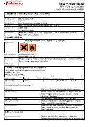
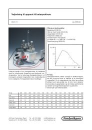
4. Use the spreadsheet program or calculator to create a table like the one shown in the following<br />
figure. In the first column, place the exact or true wavelength of the spectral lines that you used.<br />
In the second column of this worksheet, place the observed pixel number. In the third column,<br />
calculate the pixel number squared, <strong>and</strong> in the fourth column, calculate the pixel number cubed.<br />
14 170-00000-RT-02-1106
A: Calibrating the Wavelength of the <strong>Red</strong> <strong>Tide</strong><br />
Independent<br />
Variable<br />
Dependent<br />
Variables<br />
Values Computed<br />
from the Regression<br />
Output<br />
True Wavelength (nm) Pixel # Pixel # 2 Pixel # 3 Predicted<br />
Wavelength<br />
253.65<br />
296.73<br />
302.15<br />
313.16<br />
334.15<br />
365.02<br />
404.66<br />
407.78<br />
435.84<br />
546.07<br />
576.96<br />
579.07<br />
696.54<br />
706.72<br />
727.29<br />
738.40<br />
751.47<br />
175<br />
296<br />
312<br />
342<br />
402<br />
490<br />
604<br />
613<br />
694<br />
1022<br />
1116<br />
1122<br />
1491<br />
1523<br />
1590<br />
1627<br />
1669<br />
30625<br />
87616<br />
97344<br />
116964<br />
161604<br />
240100<br />
364816<br />
375769<br />
481636<br />
1044484<br />
1245456<br />
1258884<br />
2223081<br />
2319529<br />
2528100<br />
2647129<br />
2785561<br />
5359375<br />
25934336<br />
30371328<br />
40001688<br />
64964808<br />
117649000<br />
220348864<br />
230346397<br />
334255384<br />
1067462648<br />
1389928896<br />
1412467848<br />
3314613771<br />
3532642667<br />
4019679000<br />
4306878883<br />
4649101309<br />
253.56<br />
296.72<br />
302.40<br />
313.02<br />
334.19<br />
365.05<br />
404.67<br />
407.78<br />
435.65<br />
546.13<br />
577.05<br />
579.01<br />
696.70<br />
706.62<br />
727.24<br />
738.53<br />
751.27<br />
Difference<br />
5. Use the spreadsheet or calculator to calculate the wavelength calibration coefficients. In the<br />
spreadsheet program, find the functions to perform linear regressions.<br />
• If using Quattro Pro, look under Tools | Advanced Math<br />
• If using Excel, look under Analysis ToolPak<br />
6. Select the true wavelength as the dependent variable (Y). Select the pixel number, pixel number<br />
squared, <strong>and</strong> the pixel number cubed as the independent variables (X). After executing the<br />
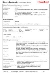
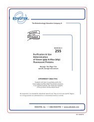
regression, you will obtain an output similar to the one shown below. Numbers of importance are<br />
noted.<br />
Regression Statistics<br />
Multiple R 0.999999831<br />
R Square 0.999999663 R Squared<br />
Adjusted R Square 0.999999607<br />
St<strong>and</strong>ard Error 0.125540214<br />
Observations 22<br />
Intercept<br />
Coefficients St<strong>and</strong>ard Error<br />
Intercept 190.473993 0.369047536 First coefficient<br />
X Variable 1 0.36263983 0.001684745<br />
X Variable 2-1.174416E-05 8.35279E-07<br />
X Variable 3-2.523787E-09 2.656608E-10 Second coefficient<br />
Third coefficient<br />
0.09<br />
0.01<br />
-0.25<br />
0.13<br />
-0.05<br />
-0.04<br />
-0.01<br />
0.00<br />
0.19<br />
-0.06<br />
-0.09<br />
0.06<br />
-0.15<br />
0.10<br />
0.06<br />
-0.13<br />
0.19<br />
170-00000-RT-02-1106 15
A: Calibrating the Wavelength of the <strong>Red</strong> <strong>Tide</strong><br />
7. Record the Intercept, as well as the First, Second, <strong>and</strong> Third Coefficients. Additionally, look at<br />
the value for R squared. It should be very close to 1. If not, you have most likely assigned one of<br />
your wavelengths incorrectly.<br />
Keep these values at h<strong>and</strong>.<br />
Saving the New Calibration Coefficients: USB<br />
Mode<br />
Ocean <strong>Optic</strong>s programs wavelength calibration coefficients unique to each <strong>Red</strong> <strong>Tide</strong> onto an EEPROM<br />
memory chip in the <strong>Red</strong> <strong>Tide</strong>.<br />
You can overwrite old calibration coefficients on the EEPROM if you are using the <strong>Red</strong> <strong>Tide</strong> via the USB<br />
port.<br />
► Procedure<br />
To save wavelength calibration coefficients using the USB mode, perform the following steps:<br />
1. Ensure that the <strong>Red</strong> <strong>Tide</strong> is connected to the computer <strong>and</strong> that you have closed all other<br />
applications.<br />
2. Point your browser to http://www.oceanoptics.com/technical/softwaredownloads.asp <strong>and</strong><br />
scroll down to Microcode. Select USB EEPROM Programmer.<br />
3. Save the setup file to your computer.<br />
4. Run the Setup.exe file to install the software. The Welcome screen appears.<br />
5. Click the Next button. The Destination Location screen appears.<br />
6. Accept the default installation location, or click the Browse button to specify a directory. Then,<br />
click the Next button. The Program Manager Group screen appears.<br />
7. Click the Next button. The Start <strong>Installation</strong> screen appears.<br />
8. Click the Next button to begin the installation. Once the installation finishes, the <strong>Installation</strong><br />
Complete screen appears.<br />
9. Click the Finish button <strong>and</strong> reboot the computer when prompted.<br />
10. Navigate to the USB EEPROM Programmer from the Start menu <strong>and</strong> run the software.<br />
11. Click on the desired <strong>Red</strong> <strong>Tide</strong> device displayed in the left pane of the USB Programmer screen.<br />
12. Double-click on each of the calibration coefficients displayed in the right pane of the USB<br />
Programmer screen <strong>and</strong> enter the new values acquired in Steps 5 <strong>and</strong> 6 of the Calibrating the<br />
Wavelength of the <strong>Spectrometer</strong> section in this appendix.<br />
13. Repeat Step 12 for all of the new values.<br />
14. Click on the Save All Values button to save the information, <strong>and</strong> then Exit the USB Programmer<br />
software.<br />
The new wavelength calibration coefficients are now loaded onto the EEPROM memory chip on the <strong>Red</strong><br />
<strong>Tide</strong>.<br />
16 170-00000-RT-02-1106
Appendix B<br />
External Triggering<br />
Overview<br />
The <strong>Red</strong> <strong>Tide</strong> supports three triggering modes, which are set with the Trigger Mode comm<strong>and</strong>. A detail of<br />
each triggering mode follows.<br />
Normal (Free Running)<br />
In this mode, the <strong>Red</strong> <strong>Tide</strong> uses the user-defined integration clock <strong>and</strong> continuously scans the CCD array.<br />
External Software Trigger<br />
In this mode, the <strong>Red</strong> <strong>Tide</strong> uses the user-defined integration clock; however, the A/D converter is required<br />
to wait until the Trigger Input Signal goes HIGH before it acquires the data at the start of the next<br />
integration period. This is an asynchronous trigger mode that allows the user to define an integration<br />
period.<br />
External Hardware Trigger<br />
In this mode, the <strong>Red</strong> <strong>Tide</strong> uses an internally generated clock to generate the integration period. On the<br />
rising edge of this signal, the internal logic resets the CCD array, integrates for 50ms. This is a<br />
synchronous trigger mode but the integration time is fixed. OEMs can contact Ocean <strong>Optic</strong>s for other<br />
periods.<br />
170-00000-RT-02-1106 17
B: External Triggering<br />
18 170-00000-RT-02-1106
Appendix C<br />
Specifications<br />
Overview<br />
This appendix contains information on spectrometer operation, specifications, <strong>and</strong> system compatibility.<br />
It also includes accessory connector pinout diagrams <strong>and</strong> pin-specific information.<br />
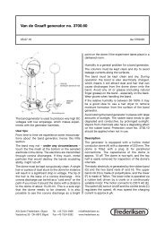
How the <strong>Red</strong> <strong>Tide</strong> Works<br />
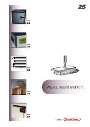
Below is a diagram of how light moves through the optical bench of an <strong>Red</strong> <strong>Tide</strong> <strong>Spectrometer</strong>. The<br />
optical bench has no moving parts that can wear or break; all the components are fixed in place at the time<br />
of manufacture. Items with an asterisk (*) are user-specified.<br />
<strong>Red</strong> <strong>Tide</strong> <strong>Spectrometer</strong> with Components<br />
See <strong>Red</strong> <strong>Tide</strong> Components Table on the following page for an explanation of the function of each<br />
numbered component in the <strong>Red</strong> <strong>Tide</strong> <strong>Spectrometer</strong> in this diagram.<br />
170-00000-RT-02-1106 19
C: Specifications<br />
<strong>Red</strong> <strong>Tide</strong> Components Table<br />
Ocean <strong>Optic</strong>s permanently secures all components in the <strong>Red</strong> <strong>Tide</strong> at the time of manufacture. Only<br />
Ocean <strong>Optic</strong>s technicians can replace interchangeable components, where noted.<br />
Item Name Description<br />
1<br />
SMA 905<br />
Connector<br />
Secures the input fiber to the spectrometer. Light from the input fiber enters the<br />
optical bench through this connector.<br />
2 Slit<br />
3 Filter<br />
A dark piece of material containing a rectangular aperture, which is mounted directly<br />
behind the SMA Connector. The size of the aperture (from 5 µm to 200 µm)<br />
regulates the amount of light that enters the optical bench <strong>and</strong> controls spectral<br />
resolution.<br />
You can also use the <strong>Red</strong> <strong>Tide</strong> without a Slit. In this configuration, the diameter of<br />
the fiber connected to the <strong>Red</strong> <strong>Tide</strong> determines the size of the entrance aperture.<br />
Only Ocean <strong>Optic</strong>s technicians can change the Slit.<br />
Restricts optical radiation to pre-determined wavelength regions. Light passes<br />
through the Filter before entering the optical bench. Both b<strong>and</strong>pass <strong>and</strong> longpass<br />
filters are available to restrict radiation to certain wavelength regions.<br />
Only Ocean <strong>Optic</strong>s technicians can change the Filter.<br />
4<br />
Collimating<br />
Mirror<br />
Focuses light entering the optical bench towards the Grating of the spectrometer.<br />
Specify st<strong>and</strong>ard or SAG+.<br />
Light enters the spectrometer, passes through the SMA Connector, Slit, <strong>and</strong> Filter,<br />
<strong>and</strong> then reflects off the Collimating Mirror onto the Grating.<br />
5 Grating<br />
Diffracts light from the Collimating Mirror <strong>and</strong> directs the diffracted light onto the<br />
Focusing Mirror.<br />
Only Ocean <strong>Optic</strong>s technicians can change the Grating.<br />
6<br />
7<br />
8<br />
Focusing<br />
Mirror<br />
L4 Detector<br />
Collection<br />
Lens<br />
Detector<br />
(UV or VIS)<br />
Receives light reflected from the Grating <strong>and</strong> focuses first-order spectra onto the<br />
detector plane.<br />
An optional component that attaches to the Detector to increase light-collection<br />
efficiency. It focuses light from a tall slit onto the shorter Detector elements.<br />
The L4 Detector Collection Lens should be used with large diameter slits or in<br />
applications with low light levels. It also improves efficiency by reducing the effects<br />
of stray light.<br />
Only Ocean <strong>Optic</strong>s technicians can add or remove the L4 Detection Collection Lens.<br />
Collects the light received from the Focusing Mirror or L4 Detector Collection Lens<br />
<strong>and</strong> converts the optical signal to a digital signal. Each pixel on the Detector<br />
responds to the wavelength of light that strikes it, creating a digital response. The<br />
spectrometer then transmits the digital signal to the SpectraSuite application.<br />
20 170-00000-RT-02-1106
C: Specifications<br />
Item Name Description<br />
9<br />
10<br />
OFLV<br />
Filters<br />
UV4<br />
Detector<br />
Upgrade<br />
OFLV Variable Longpass Order-sorting Filters block second- <strong>and</strong> third-order light.<br />
These filters are optional.<br />
The detector’s st<strong>and</strong>ard window is replaced with a quartz window to enhance<br />
spectrometer performance (99.8%<br />
<strong>Red</strong> <strong>Tide</strong> <strong>Spectrometer</strong><br />
Specification<br />
Dimensions<br />
Weight<br />
Power consumption<br />
Value<br />
89.1 mm x 63.3 mm x 34.4 mm<br />
190 g<br />
90 mA @ 5 VDC<br />
170-00000-RT-02-1106 21
C: Specifications<br />
Specification<br />
Detector<br />
Detector range<br />
Entrance aperture<br />
Order-sorting filters<br />
Focal length<br />
<strong>Optic</strong>al resolution<br />
Stray light<br />
Dynamic range<br />
<strong>Fiber</strong> optic connector<br />
Data transfer rate<br />
Integration time<br />
Interfaces<br />
Operating systems<br />
Analog channels<br />
Value<br />
2048-element linear silicon CCD array<br />
200-1100 nm<br />
25 µm-wide slit<br />
Installed longpass <strong>and</strong> b<strong>and</strong>pass filters<br />
42 mm input; 68 mm output<br />
~2.0 nm FWHM<br />
C: Specifications<br />
10-Pin Accessory Connector Pinout<br />
The <strong>Red</strong> <strong>Tide</strong> features a 10-pin Accessory Connector, located on the front of the unit as shown:<br />
10-Pin Connector<br />
Location of <strong>Red</strong> <strong>Tide</strong> 10-Pin Accessory Connector<br />
10-Pin Accessory Connector Pinout Diagram<br />
When facing the 10-pin Accessory Connector on the front of the vertical wall of the <strong>Red</strong> <strong>Tide</strong>, pin<br />
numbering is as follows:<br />
10-Pin Accessory Connector Pinout Diagram<br />
170-00000-RT-02-1106 23
C: Specifications<br />
10-Pin Accessory Connector – Pin Definitions <strong>and</strong><br />
Descriptions<br />
The following table contains information regarding the function of each pin in the <strong>Red</strong> <strong>Tide</strong>’s 10-Pin<br />
Accessory Connector:<br />
Pin<br />
#<br />
Function Input/Output Description<br />
1<br />
V CC , V USB ,<br />
or 5V IN<br />
Input or<br />
Output<br />
Input power pin for <strong>Red</strong> <strong>Tide</strong> – When operating via USB, this pin<br />
can power other peripherals – Ensure that peripherals comply with<br />
USB specifications<br />
2 RS232 Tx Output<br />
3 RS232 Rx Input<br />
RS232 transmit signal – Communicates with a computer over DB9<br />
Pin 2<br />
RS232 receive signal – Communicates with a computer over DB9<br />
Pin 3<br />
4<br />
Lamp<br />
Enable<br />
Output<br />
TTL signal driven Active HIGH when the Lamp Enable comm<strong>and</strong><br />
is sent to the spectrometer<br />
5<br />
Continuous<br />
Strobe<br />
Output<br />
TTL output signal used to pulse a strobe – Divided down from the<br />
master clock signal<br />
6 Ground Input/Output Ground<br />
7<br />
External<br />
Trigger In<br />
Input<br />
TTL input trigger signal – See External Triggering Options<br />
document for info<br />
8<br />
Single<br />
Strobe<br />
Output<br />
TTL output pulse used as a strobe signal – Has a programmable<br />
delay relative to the beginning of the spectrometer integration<br />
period<br />
9 I 2 C SCL Input/Output The I 2 C clock signal for communications to other I 2 C peripherals.<br />
10 I 2 C SDA Input/Output The I 2 C Data signal for communications to other I 2 C peripherals.<br />
24 170-00000-RT-02-1106
Index<br />
Numbers<br />
F<br />
10-pin accessory connector filter, 20<br />
diagram, 23 focusing mirror, 20<br />
pin definitions, 24<br />
A<br />
accessories, 5, 8<br />
Accessories, 3<br />
accessory connector<br />
pinout, 23<br />
Adobe Acrobat Reader, 4<br />
C<br />
Calibrating, iii, 13<br />
calibration, 13<br />
preparing for, 14<br />
procedure, 14<br />
calibration coefficients<br />
saving in USB mode, 16<br />
CCD, 21<br />
CCD Detector, 20<br />
collimating mirror, 20<br />
Components Table, 20<br />
D<br />
detector, 21<br />
Detector Collection Lens, 20<br />
document<br />
audience, iii<br />
purpose, iii<br />
summary, iii<br />
E<br />
EEPROM, 2<br />
external triggering, 8, 17<br />
grating, 20<br />
<strong>Installation</strong>, 7<br />
installed filter, 20<br />
G<br />
I<br />
L<br />
L2 Detector Collection Lens, 20<br />
Lens, 20<br />
light sources, 3<br />
memory chip, 2<br />
mirror, 20<br />
M<br />
P<br />
packing list, 4<br />
passwords, 4<br />
product-related documentation, iii<br />
<strong>Red</strong> <strong>Tide</strong><br />
specifications, 21<br />
R<br />
170-00000-RT-02-1106 25
Index<br />
S<br />
T<br />
Sampling triggering, 8, 17<br />
Accessories, 3 troubleshooting, 9<br />
System, 3 Linux systems, 11<br />
setup, 7 Mac systems, 10<br />
shipment components, 4 Windows systems, 9<br />
slit, 20<br />
SMA Connector, 20<br />
Software <strong>and</strong> Resources Library CD, 4<br />
specifications, 19<br />
detector, 21<br />
upgrades, iv<br />
<strong>Red</strong> <strong>Tide</strong>, 21<br />
SpectraSuite, 3<br />
spectroscopic accessories, 8<br />
System Requirements, 2<br />
U<br />
W<br />
Wavelength Calibration<br />
about, 13<br />
Wavelength Calibration Data File, 4<br />
Wavelength Calibration Data Sheet, 4<br />
26 170-00000-RT-02-1106