SEDEX* - Foseco
SEDEX* - Foseco
SEDEX* - Foseco
- No tags were found...

Create successful ePaper yourself
Turn your PDF publications into a flip-book with our unique Google optimized e-Paper software.
COATINGS FILTRATION FEEDING SYSTEMS MELT SHOP REFRACTORIES METAL TREATMENT BINDERS CRUCIBLES<br />
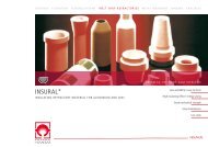
THE FILTER FOR MORE COST EFFECTIVE CASTING PRODUCTION<br />
<strong>SEDEX*</strong><br />
THE CERAMIC FOAM FILTER<br />
Highest efficiency<br />
Even filling<br />
Scrap reduction<br />
Improved machinability<br />
Improved yield
SEDEX foundry filters<br />
Proven technology a billion times over<br />
Trusted performance<br />
SEDEX foundry filters have been used by the foundry<br />
industry for more than 25 years. During this time,<br />
the filter and its application have been continuously<br />
improved in co-operation with leading foundries<br />
around the world. The use of SEDEX foundry filters is<br />
a guaranteed way to produce quality, cost effective<br />
castings. For these reasons the use of SEDEX foundry<br />
filters has become state-of-the-art in many foundries.<br />
As the most commonly used foundry filter in the<br />
world, SEDEX foundry filter are proven in its ability to<br />
fulfill customer demands.<br />
The application of SEDEX foundry filters for the<br />
production of the most demanding castings ensures<br />
that the full mechanical and dynamic properties of the<br />
casting alloy can be achieved. The use of conventional<br />
gating systems, even with generously dimensioned<br />
runner bars, is not sufficient to retain enough slag<br />
and suspended reaction products to meet the high<br />
quality standards of today‘s castings. These demands<br />
can be readily and consistently achieved with the help<br />
of SEDEX foundry filters.<br />
2
SEDEX gating systems result in<br />
• compact, short and direct systems<br />
• less returns<br />
• more free pattern plate area<br />
• lower melting costs per poured spray<br />
• effective retention of slag and sand<br />
contamination<br />
• reduced scrap risk<br />
• increased process security<br />
• improved physical properties of the casting<br />
• improved accuracy of scrap diagnosis<br />
Application technique<br />
<strong>Foseco</strong> offers unrivalled customer support. Depending<br />
on the problem, <strong>Foseco</strong> can offer support such as:<br />
• Metallurgical investigation of casting defects<br />
• Optimisation of pattern plate layouts with the<br />
support of mould fill and solidification simulation<br />
• Application support in the foundry<br />
Original layout<br />
Targeted layout<br />
Simulation and<br />
optimisation of the layout<br />
Improved layout<br />
3
SEDEX foundry filters<br />
Highest filtration efficiency and smooth mould filling<br />
High filtration efficiency<br />
The acknowledged effectiveness of SEDEX foundry<br />
filters is a result of their foam structure. Some of the<br />
volume consists of open, reticulated, interconnected<br />
pores providing a plurality of direction and velocity<br />
changes in the liquid metal flow. This leads to<br />
intensive contact with the filter surface which<br />
allows small non-metallic particles to be retained<br />
within the foam structure; they are not just sieved<br />
out on the product entry face.<br />
This filter mechanism known as deep bed filtration<br />
and is only present in multi-dimensional structures<br />
like the SEDEX ceramic foam filters.<br />
The shape of a single pore looks like a pentagondodecahedron.<br />
4
The structure of SEDEX filters efficiently retains sand<br />
and slag as well as reaction products from magnesium<br />
treatment. An often underestimated but nevertheless<br />
very important advantage of ceramic foam filters is<br />
their ability to reduce the turbulence in the molten<br />
metal stream. This helps to ensure an even mould<br />
filling and protect the metal from re-oxidation.<br />
The pictures below have been generated by real time<br />
x-ray and illustrate the metal flow into the mould<br />
cavity when different filter types are used.<br />
The red frame marks the filter position.<br />
Sand<br />
Metal flow into the mould cavity through an extruded filter<br />
Metal flow into the mould cavity through a ceramic foam filter<br />
Silicate slag<br />
Magnesium sulphide<br />
5
SEDEX foundry filters<br />
Calculation of choke and filter area<br />
The application of SEDEX foundry filters is performed<br />
in three steps:<br />
Step 1<br />
Calculation of gating systems with filters<br />
The mould filling speed and filling pattern is<br />
determined by the dimensions and design of the<br />
gating system. The time to complete the pouring<br />
sequence is determined by the smallest crosssection<br />
in the system. In the case of conventional<br />
gating systems, this choke, or controlling section, is<br />
the total area of the ingates. In gating systems for<br />
use with SEDEX foundry filters, the cross-section of<br />
the downsprue becomes the smallest or controlling<br />
section for the system.<br />
In the case of moulding lines where a standardised<br />
downsprue is used, the controlling section must<br />
be placed in the runner bar directly behind the<br />
downsprue.<br />
The calculation of the dimension of the controlling<br />
section for a specific gating system can be simply<br />
performed using the following formula:<br />
DA : downsprue area [cm 2 ]<br />
22.6 : constant for acceleration<br />
G : poured weight [kg]<br />
: friction factor<br />
: density [g/cm 3 ]<br />
t : required pouring time [s]<br />
H : effective pressure or pouring height [cm]<br />
In order to ensure that the filling progresses evenly<br />
within the whole mould, it is recommended that all<br />
the runner bars are located in the drag and all the<br />
ingates are located at the top of the runners.<br />
6
ht<br />
ting system<br />
practice:<br />
(s)<br />
increase in<br />
lence mould<br />
have to be<br />
, the runner<br />
ars and the<br />
uired.<br />
Calculation of effective pouring height<br />
The following relationship between the gating system<br />
components has proven very successful in practice:<br />
Step 2<br />
Determine the SEDEX filter area, type, number<br />
and porosity. The required filter area will be<br />
influenced by the following factors:<br />
■ The smallest cross-section in the gating system<br />
■ Filter capacity (kg/cm²)<br />
■ Poured weight<br />
This gating system ratio with a progressive increase in<br />
cross-section encourages quiet, low turbulence mould<br />
filling. The resulting cross-sectional areas have to be<br />
allocated according to the pattern layout. The runner<br />
area is divided by the number of runner bars and the<br />
ingate area by the number of ingates required.<br />
■ Level of metallurgical contamination<br />
■ In the case of ductile iron the treatment technique,<br />
%Mg alloy addition and the sulphur level before<br />
treatment<br />
The selected filter area can either be applied as a<br />
single filter or in the case of a large area, a number<br />
of smaller filters. In the latter case they should be<br />
positioned as close as possible to the mould cavity so<br />
that the maximum amount of inclusion material can<br />
be collected.<br />
Filtration capacity is influenced by many process<br />
variables, therefore the above values should only be<br />
regarded as guidelines.<br />
Filter capacity<br />
kg/cm 2<br />
0.5 - 1.0<br />
downsprue runner ingate(s)<br />
1.0 : 1.1 : 1.2<br />
Step 2<br />
Determine the SEDEX filter area, type, number and porosity<br />
The required filter area will be influenced by the<br />
following factors:<br />
• The smallest cross-section in the gating system<br />
Iron Alloy<br />
• Filter capacity (kg/cm²)<br />
NiResist, SiMo, D5<br />
• Poured weight<br />
Ductile (Inmold)<br />
• Level of metallurgical contamination<br />
• In the case of ductile iron, the treatment technique,<br />
%Mg alloy addition and the sulphur level before<br />
treatment<br />
1.0 - 2.0 Ductile<br />
2.0 - 4.0 Grey/Malleable<br />
According to our application experience we<br />
recommend that for high alloyed ductile iron (e.g.<br />
NiResist or SiMo) a filter area which is 4 times as<br />
big as the downsprue area. For ductile iron we<br />
recommend a ratio of Downsprue:Filter area of 1:3,<br />
for grey and malleable iron we recommend at least<br />
a ratio of 1:2. These ratios ensure that the pouring<br />
time is determined by the downsprue area and not<br />
by the filter.<br />
The selected filter area can either be applied as a<br />
single filter or in the case of a large area, a number<br />
of smaller filters. In the latter case they should be<br />
positioned as close as possible to the mould cavity<br />
so that the maximum amount of inclusion material<br />
can be collected.<br />
Filtration capacity is influenced by many process<br />
variables, therefore the following values should only<br />
be regarded as guidelines.<br />
Filter capacity kg/cm2<br />
0.5 - 1.0<br />
Iron alloy<br />
NiResist, SiMo,<br />
Ductile (Inmold)<br />
1.0 - 2.0 Ductile / Vermicular<br />
2.0 - 4.0 Grey/Malleable<br />
According to application experience we recommend<br />
that for high alloyed ductile iron (e.g. NiResist or<br />
SiMo) a filter area which is 4 times as big as the<br />
downsprue area.<br />
For ductile iron we recommend a ratio of<br />
Downsprue:Filter area of 1:3, for grey and malleable<br />
iron we recommend at least a ratio of 1:2.<br />
These ratios ensure that the pouring time is determined<br />
by the downsprue area and not by the filter.<br />
7
SEDEX foundry filters<br />
Selection of porosity and filter position<br />
In the introductory phase, it is recommended that the<br />
filter area should be generously dimensioned. The<br />
resulting filter sizes can be optimised once sufficient<br />
application experience has been acquired in a given<br />
foundry environment.<br />
Filter porosity is generally determined by the alloy to<br />
be poured. Ductile iron and the special alloy types<br />
Ni-resist and SiMo contain a high level of reaction<br />
products and the coarse (10 ppi) SEDEX filter is<br />
normally applied. Process improvements giving a<br />
lower level of reaction products have allowed some<br />
foundries to work with the finer (20 ppi) filtration<br />
product, but this is still an exception.<br />
Grey iron which contains lower levels of reaction<br />
products is normally filtered using 20 ppi SEDEX<br />
filter. 30 ppi products may be applied if the molten metal is<br />
very clean.<br />
Malleable iron with the lowest level of metallurgical<br />
contamination and high pouring temperatures has<br />
good pouring characteristics and the fine 30 ppi<br />
porosity SEDEX filter can be applied.<br />
The extra fine 40 ppi porosity is used mainly for grey<br />
iron castings produced on vertically parted moulding<br />
lines.<br />
8
Step 3<br />
Selection of the appropriate SEDEX filter print<br />
Filtration effectiveness is in great measure<br />
dependent upon the correct installation of the<br />
filter. To assist foundries in this operation <strong>Foseco</strong><br />
has developed a range of filter position prints.<br />
It is strongly recommended that foundries take<br />
advantage of their availability – use of the SEDEX<br />
filter position prints will help to ensure correct<br />
position, entry face area and exit face support<br />
for the selected filter type. In many cases the<br />
application position of the filter and suitable filter<br />
print will, to a great extent, be decided by the<br />
layout of the pattern plate.<br />
vertically<br />
vertically<br />
vertically<br />
Specially designed filter prints are also available for<br />
use in connection with vertically parted moulds (such<br />
as DISAMATIC moulding machines). They are basically<br />
of two types for different application circumstances:<br />
1. Positioning of the filter by hand in a specially<br />
designed pouring bush.<br />
2. Positioning of the filter lower in the mould; this<br />
requires the availability of a coresetter to mechanically<br />
place the filter in the open mould half in the short<br />
time available and with the necessary accuracy.<br />
horizontally<br />
inclined<br />
horizontally<br />
9
SEDEX foundry filters<br />
Application in vertically parted moulds<br />
SEDEX application in vertically parted moulds<br />
The advantages of using SEDEX filters in vertically<br />
parted moulds:<br />
• Improved control over mould filling<br />
• Reduced mould filling velocity<br />
• Reduced turbulence and erosion<br />
• Fewer surface and gas defects<br />
• Improved machinability<br />
In the case of vertically parted moulds there are<br />
some extra aspects which need to be taken into<br />
consideration when calculating and designing the<br />
gating system.<br />
Moulds can be divided into three basic categories:<br />
1. Single cavity<br />
2. Two or more cavities at the same level<br />
3. Two or more levels of cavities<br />
As well as the three types of mould, the position of<br />
the ingate(s) must be taken into account - the lower<br />
the cavity in the mould, the smaller the ingates<br />
should be in order to ensure even filling of the<br />
complete spray of castings. To assist in achieving<br />
this, the position of the controlling section or choke<br />
also needs to be considered. Each of the three cavity<br />
types can be ingated in one of three ways, giving a<br />
total of nine gating system variations.<br />
10
a] Bottom gated:<br />
A downsprue controlled system can be applied, the<br />
cross-section of runner(s) and ingate(s) can each be<br />
increased by 10%.<br />
b] Side gated:<br />
The controlling section should be located just in front<br />
of the ingate(s) - the latter section can be increased<br />
by 10%.<br />
c] Top gated:<br />
Gating through a feeder or KALPUR unit, the<br />
controlling section must be positioned at the<br />
ingate(s); any runner or downsprue sections should<br />
be larger than that of the ingate(s). This is essentially<br />
a conventional vertical gating system.<br />
In all cases the choke section must be located behind<br />
the filter; this will ensure that it is fully primed with<br />
liquid metal for the whole pouring operation. It is<br />
important that the filter is located in a correctly<br />
designed and dimensioned filter print. The print must<br />
ensure that the filter cannot move or fall out as the<br />
mould is blown out or moved and it is essential that<br />
the print provides good exit face support during<br />
pouring.<br />
The introduction of additional friction to a gating<br />
system for vertical moulding lines (such as an inclined<br />
downsprue or sprue cross over) reduces the velocity<br />
and makes the mould filling more even. An example<br />
is shown on the right. Specific application issues<br />
can be addressed by contacting one of our product<br />
managers.<br />
Gating system<br />
with filter<br />
Turbulent<br />
mould<br />
filling,<br />
the metal<br />
impacts<br />
directly<br />
against the<br />
mould cod<br />
Gating<br />
system<br />
with<br />
inclined<br />
downsprue,<br />
cross over<br />
and filter<br />
More even<br />
and less<br />
turbulent<br />
mould filling<br />
11
SEDEX quality is assured<br />
Quality management<br />
The <strong>Foseco</strong> quality management system is certified<br />
against DIN ISO 9001:2008 and ISO 14001:2004.<br />
All relevant product quality features of SEDEX filters<br />
are controlled and recorded according to these<br />
quality standards.<br />
Impingement<br />
testing unit<br />
Important product attributes monitored in this way<br />
include:<br />
• Filter dimensions<br />
• Filter weight<br />
• Cold compression strength<br />
• Porosity<br />
• Thermal shock resistance (impingement test)<br />
Next to filtration effectiveness, thermal shock and<br />
erosion resistance to the flowing liquid iron are the<br />
most important product attributes. These properties<br />
are evaluated regularly using liquid cast iron.<br />
A special test procedure, the impingement test,<br />
has been specifically developed for this purpose.<br />
Extensive use of this test has enabled <strong>Foseco</strong> to<br />
continually improve the quality and consistency of<br />
the SEDEX iron filter.<br />
It ensures that the filter is to severe evaluation in the<br />
most practical and relevant manner possible before<br />
produced filters are released for dispatch.<br />
Dimensional<br />
inspection<br />
Testing<br />
cold<br />
compression<br />
05/2011 · re 750 e<br />
*FOSECO, the Logo and SEDEX are trade marks of the Vesuvius Group, registered in certain countries, used under licence. All rights reserved. No part of this publication may be reproduced, stored in a retrieval<br />
system of any nature or transmitted in any form or by any means, including photocopying and recording, without the written permission of the copyright holder or as expressly permitted by law. Applications for<br />
permission shall be made to the publisher at the address mentioned.<br />
Warning: The doing of an unauthorised act in relation to a copyright work may result in both a civil claim for damages and criminal prosecution. All statement, information and data contained herein are published<br />
as a guide and although believed to be accurate and reliable (having regard to the manufacturer’s practical experience) neither the manufacturer, licensor, seller nor publisher represents nor warrants, expressly<br />
or impliedly: (1) their accuracy/reliability, (2) that the use of the product(s) will not infringe third party rights, (3) that no further safety measures are required to meet local legislation. The seller is not authorised<br />
to make representations nor contract on behalf of the manufacturer/licensor. All sales by the manufacturer/seller are based on their respective conditions of sale available on request.<br />
© <strong>Foseco</strong> International Limited 05/11.<br />
COMMITTED TO FOUNDRIES<br />
<strong>Foseco</strong> International Limited<br />
Drayton Manor Business Park,<br />
Tamworth, Staffordshire,<br />
England B78 3TL<br />
Phone: +44 (0)1827 262021<br />
Fax: +44 (0)1827 283725<br />
www.foseco.com<br />
Please contact your local <strong>Foseco</strong> company