

Shadow Impact Module Version 3 Quick Information - Cape Cod ...
Shadow Impact Module Version 3 Quick Information - Cape Cod ...
Shadow Impact Module Version 3 Quick Information - Cape Cod ...

Create successful ePaper yourself
Turn your PDF publications into a flip-book with our unique Google optimized e-Paper software.
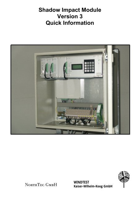
<strong>Shadow</strong> <strong>Impact</strong> <strong>Module</strong><br />
<strong>Version</strong> 3<br />
<strong>Quick</strong> <strong>Information</strong><br />
NorthTec GmbH<br />
WINDTEST<br />
Kaiser-Wilhelm-Koog GmbH
<strong>Shadow</strong> <strong>Impact</strong><br />
During sunny times of the day, the operation of wind<br />
turbine generators (WTG) may cause annoying<br />
periodic shadow impact to adjacent buildings. For this<br />
reason, building permits for the erection of WTGs<br />
increasingly demand the integration of automatic shutdown<br />
devices in order to prevent adjacent buildings<br />
from being impacted more than acceptable according<br />
to the recommended values. The shadow impact<br />
module introduced herein serves as a technical<br />
solution for meeting these demands.<br />
Functionality<br />
The light sensor of the shadow impact module<br />
periodically measures the intensity of the sun’s visible<br />
radiation. Using the results, the module determines<br />
whether the intensity of the visible direct sun radiation<br />
is capable of causing shadow impact. At the same<br />
time, the shadow impact module calculates whether<br />
shadow impact occurs in a place of immission. In case<br />
the intensity of the direct sun radiation is capable of<br />
causing shadow impact and shadow impact is<br />
detected in a place of immission, the counters for daily<br />
and annual shadow impact are updated in cycles of 1<br />
minute. If one of the limit values set is exceeded in this<br />
place of immission , the WTG responsible is shut<br />
down for the duration of the shadow impact. Because<br />
the calculations require the exact time, the shadow<br />
impact module is equiped with a radio controlled clock.<br />
Planing <strong>Information</strong><br />
One shadow impact module can control the shadow<br />
impact of up to fifty WTGs in up to 100 places of<br />
immission and log the information of a full year. When<br />
limit values are exceeded, up to 12 WTGs can be shut<br />
down. In cases where more than 12 WTGs may need<br />
to be shut down, several shadow impact modules can<br />
be operated in parallel. A telecommunication cable or<br />
optical waveguide network existing on the wind farm<br />
can be used to control the WTG. The radiation sensor<br />
and the radio controlled clock need to be connected<br />
electrically to the shadow impact module. Therefore,<br />
when erecting the WTG, provide for cabling from the<br />
outside to the inside of the WTG (e.g. through an<br />
empty conduit or an existing drilling hole in the tower).<br />
Programming<br />
For programming of the shadow impact module, the<br />
location coordinates (Gauss-Krueger) of the WTG and<br />
of the place of immission to be monitored are required<br />
(see Appendix A). Places of immission may be<br />
indicated by several walls and areas. Separate day<br />
and year limit values can be defined for each place of<br />
immission. All data may be adjusted to the current<br />
conditions using the keyboard at any time.<br />
Unauthorized access to the data can be avoided by<br />
setting a password.<br />
Log Function (Optional)<br />
The shadow impact module logs relevant shadow<br />
impact events over at least one year. Each log entry is<br />
assigned with a corresponding time stamp. The log<br />
data may be retrieved in the shadow memory software<br />
using the serial interface of the shadow impact<br />
module. Manipulating the logs is not possible.<br />
Sound Option<br />
The sound option of the shadow impact module<br />
enables shutting down the WTG for predefined periods<br />
of time. These periods which can be defined for each<br />
WTG individually may refer to certain days of the week<br />
or certain periods specified by date.<br />
Installation<br />
The shadow impact module is installed in the tower<br />
base of the WTG using upright consoles. The cabinet<br />
is powered by a 230 Volts AC Mains Power source.<br />
For each WTG to be controlled, there is a floating<br />
relay contact (normally closed contact/ normally open<br />
contact) available. The light sensor and the radio<br />
controlled clock are mounted directly to the outside of<br />
the tower using a stainless clamp causing absolutely<br />
no damage to the tower or its structure (Fig. 1). When<br />
positioning the radiation sensor, shadowing effects<br />
caused by obstacles such as tree rows or other WTGs<br />
must be avoided by all means.<br />
Fig. 1: Sensor mounted to the tower of a WTG<br />
Note:<br />
A calendar specifying the shut-down times is not<br />
required.<br />
Changes and errors excepted; <strong>Version</strong> 2003-09<br />
page 2 of 4
Appendix A: Configuration Data<br />
Example of a place of immission with a relevant house wall and a patio area<br />
General Data<br />
Height above sea level: 45 m<br />
Maximum duration of shadow impact per day: 30 min.<br />
Maximum duration of shadow impact per year: 480 min.<br />
Description of house wall<br />
Description of patio area<br />
x-corner coordinate 1: 350 7685 x-corner coordinate 1: 350 7685<br />
y-corner coordinate 1: 597 4637 y-corner coordinate 1: 597 4637<br />
x-corner coordinate 2: 350 7695 x-corner coordinate 2: 350 7690<br />
y-corner coordinate 2: 597 4639 y-corner coordinate 2: 597 4638<br />
Height: 3 m x-corner coordinate 3: 350 7692<br />
Orientation: South y-corner coordinate 3: 597 4632<br />
x-corner coordinate 4: 350 7687<br />
y-corner coordinate 4: 597 4630<br />
________________________________________________________________________<br />
Example of a WTG<br />
Hub height:<br />
Rotor radius:<br />
Height above sea level:<br />
100 m<br />
35 m<br />
48 m<br />
x-corner coordinate: 350 7745<br />
y-corner coordinate: 597 4229<br />
___________________________________________________________________<br />
Appendix B: Example of a Log Sequence<br />
1 04.02.2003 14.40.23 2 1 0 min 34 min theoretical shadow impact<br />
2 04.02.2003 14.45.29 2 1 0 min 34 min shadow impact<br />
3 04.02.2003 14.48.20 2 1 3 min 37 min theoretical shadow impact<br />
4 04.02.2003 14.50.54 2 1 3 min 37 min shadow impact<br />
5 04.02.2003 15.17.57 2 1 30 min 64 min Stop WTG<br />
7 04.02.2003 15.27.30 2 1 30 min 64 min end of shadow impact<br />
8 04.02.2003 15.28.44 2 1 30 min 64 min Start WTG<br />
9 04.02.2003 16.15.54 5 2 0 min 325 min shadow impact<br />
10 04.02.2003 16.22.32 5 2 6 min 331 min end of shadow impact<br />
Explanation:<br />
PI:<br />
WTG:<br />
Stop WTG:<br />
Start WTG:<br />
theoretical shadow impact:<br />
shadow impact:<br />
Place of Immission (building)<br />
Wind Turbine Generator<br />
the corresponding WTG was shut down by the shadow impact module<br />
the corresponding WTG was released<br />
the corresponding WTG causes theoretical shadow impact in the<br />
corresponding PI but the direct sun radiation is not strong enough to cause<br />
real shadow impact<br />
shadow impact actually occurs in the corresponding place of immission;<br />
the direct sun radiation is strong enough to cause real shadow impact<br />
Changes and errors excepted; <strong>Version</strong> 2003-09<br />
page 3 of 4
<strong>Shadow</strong> <strong>Impact</strong> <strong>Module</strong> Specifications<br />
Operating temperature: -20°C … 50°C<br />
Protection class: IP 65<br />
Switch Cabinet with <strong>Module</strong><br />
Dimensions: 500 x 500 x 310 mm (H x W x D)<br />
Weight:<br />
approx. 23 kg<br />
Supply voltage:<br />
230 V AC<br />
Max. power consumption: 30 W<br />
Switch outputs:<br />
floating relay contacts (normally closed contact/ normally open contact),<br />
12 max.<br />
Max. switching voltage: 60 V/AC, 125 V/DC<br />
Max. switching capacity: 62,5 VA / 30 W<br />
Radiation Sensor<br />
Dimensions: 80 x 65 x80 mm (H x W x D)<br />
Weight:<br />
approx. 11 kg (cantilever incl.)<br />
Cantilever length: 1,5 m<br />
Supply voltage:<br />
15 V DC (power supply installed inside the cabinet)<br />
Radio controlled Clock<br />
Dimensions: 90 x 90 x50 mm (H x W x D)<br />
Weight:<br />
approx. 800g<br />
Supply voltage:<br />
15 V DC (power supply installed inside the cabinet)<br />
Development and Sales<br />
WINDTEST Kaiser-Wilhelm-Koog GmbH<br />
Sommerdeich 14 b<br />
D-25709 Kaiser-Wilhelm-Koog<br />
Tel: + 49 (0)4856 901 - 0<br />
Fax: + 49 (0)4856 901 - 99<br />
swm@windtest.de<br />
Support, Installation, Maintenance<br />
and Location Survey<br />
NorthTec GmbH<br />
Horsbeker Weg 2<br />
D-24980 Schafflund<br />
Tel: + 49 (0)4639 782 046<br />
Fax: + 49 (0)4639 782 3030<br />
swm@northtec.org<br />
Changes and errors excepted; <strong>Version</strong> 2003-09<br />
page 4 of 4