Installation Guide - Gamber Johnson
Installation Guide - Gamber Johnson
Installation Guide - Gamber Johnson

You also want an ePaper? Increase the reach of your titles
YUMPU automatically turns print PDFs into web optimized ePapers that Google loves.
INSTALLATION INSTRUCTIONS<br />
Product Revision Form #<br />
GD8000 Docking Station Rev. C INST-437<br />
7160-0194-01, -02, -03, -04, -05, -06<br />
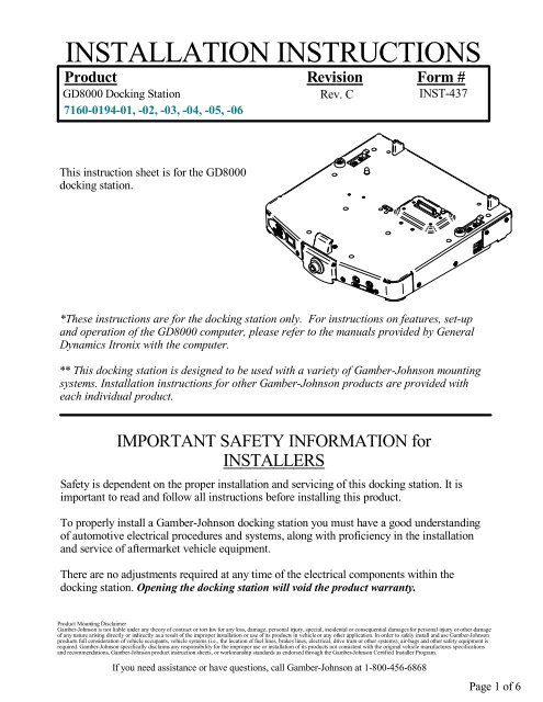
This instruction sheet is for the GD8000<br />
docking station.<br />
*These instructions are for the docking station only. For instructions on features, set-up<br />
and operation of the GD8000 computer, please refer to the manuals provided by General<br />
Dynamics Itronix with the computer.<br />
** This docking station is designed to be used with a variety of <strong>Gamber</strong>-<strong>Johnson</strong> mounting<br />
systems. <strong>Installation</strong> instructions for other <strong>Gamber</strong>-<strong>Johnson</strong> products are provided with<br />
each individual product.<br />
IMPORTANT SAFETY INFORMATION for<br />
INSTALLERS<br />
Safety is dependent on the proper installation and servicing of this docking station. It is<br />
important to read and follow all instructions before installing this product.<br />
To properly install a <strong>Gamber</strong>-<strong>Johnson</strong> docking station you must have a good understanding<br />
of automotive electrical procedures and systems, along with proficiency in the installation<br />
and service of aftermarket vehicle equipment.<br />
There are no adjustments required at any time of the electrical components within the<br />
docking station. Opening the docking station will void the product warranty.<br />
Product Mounting Disclaimer<br />
<strong>Gamber</strong>-<strong>Johnson</strong> is not liable under any theory of contract or tort law for any loss, damage, personal injury, special, incidental or consequential damages for personal injury or other damage<br />
of any nature arising directly or indirectly as a result of the improper installation or use of its products in vehicle or any other application. In order to safely install and use <strong>Gamber</strong>-<strong>Johnson</strong><br />
products full consideration of vehicle occupants, vehicle systems (i.e., the location of fuel lines, brakes lines, electrical, drive train or other systems), air-bags and other safety equipment is<br />
required. <strong>Gamber</strong>-<strong>Johnson</strong> specifically disclaims any responsibility for the improper use or installation of its products not consistent with the original vehicle manufactures specifications<br />
and recommendations, <strong>Gamber</strong>-<strong>Johnson</strong> product instruction sheets, or workmanship standards as endorsed through the <strong>Gamber</strong>-<strong>Johnson</strong> Certified Installer Program.<br />
If you need assistance or have questions, call <strong>Gamber</strong>-<strong>Johnson</strong> at 1-800-456-6868<br />
Page 1 of 6
During <strong>Installation</strong><br />
•DO NOT connect this docking station to the vehicle battery until:<br />
1. ALL other electrical connections are made<br />
2. Mounting of ALL components is complete<br />
3. VERIFICATION that no shorts exist in the entire system<br />
•DO NOT install equipment or route wiring or cords in the deployment path of any<br />
air bag.<br />
•When drilling into the vehicle, DO make sure that both sides of the surface are<br />
clear of anything that could be damaged.<br />
CAUTION: If wiring is shorted to the frame, high current conductors can cause<br />
hazardous sparks resulting in electrical fires or flying molten metal.<br />
After <strong>Installation</strong><br />
•Test the docking station to ensure that it is working properly.<br />
File these instructions in a safe place and refer to them when performing<br />
maintenance or re-installing.<br />
WARNING: Failure to follow all safety precautions and instructions may result<br />
in property damage, serious injury or death.<br />
PRE-INSTALLATION RECOMMENDATIONS<br />
Conduct a "Bench Test"<br />
<strong>Gamber</strong>-<strong>Johnson</strong> strongly advises a "bench test" be conducted to verify that all electronic<br />
and software issues are resolved prior to installation:<br />
1. Make sure computer is operational by itself.<br />
2. Insert computer into docking station and verify that the computer is operating in the<br />
dock.<br />
3. Interconnect entire assembly and verify start-up of all components, including other<br />
equipment (printers, modems, scanners, etc.).<br />
*<strong>Gamber</strong>-<strong>Johnson</strong> also recommends positioning of all mounts and equipment in the vehicle<br />
prior to the actual install to verify that mounting locations are safe and practical.<br />
Page 2 of 6
POWER SUPPLY INFORMATION<br />
This docking station has a built-in power supply and is designed to be used with an 11 - 28<br />
volt DC system. The voltage output is factory set at 19 volts and current limited to 4.5<br />
amps. Power is provided using the wires located on the back side of the docking station.<br />
WIRING INSTRUCTIONS<br />
IMPORTANT: Make sure that you have read this entire section before you begin wiring!<br />
Refer to Figure 2<br />
1. Install docking station into vehicle, making sure that all bolts are tight.<br />
2. Attach the BLACK ground wire to the location where the vehicle battery grounds to<br />
vehicle chassis.<br />
3. Attach the RED wire to the supply voltage (V+) from the vehicle.<br />
IMPORTANT REMINDERS:<br />
•Use only SAE J1128 Type GPT number 14 AWG stranded wire (minimum) to attach the<br />
docking station to the vehicle's electrical system.<br />
•Connect lead wires to the disconnect pigtail using the butt splice connectors provided with the<br />
docking station. Caution: The butt splice connections must be made as close<br />
to the docking station as possible using the disconnect pigtail provided with the docking<br />
station. The disconnect must be easily accesible. When assembling the butt splice connectors<br />
use only Panduit crimp tools CT-100, CT-600, CT-1525, CT-1550 OR CT-1551.<br />
•Route the lead wires to the battery. Total wire in the circuit must not exceed 30 feet and<br />
must conform to SAE standard J1128.<br />
•Protect the lead wires from abrasion and chafing by using wire loom or conduit, and route<br />
away from moving parts or areas where high temperatures may occur.<br />
•Connection of the supply voltage (V+) must be kept as close to the battery as possible.<br />
•The power connection must be made with the 10 amp in-line fuse and fuse holder provided<br />
with the dock. Connect the fuse holder to the lead wire using the butt splice connectors<br />
provided with fuse holder. When assembling the butt splice connectors use only Panduit<br />
crimp tools CT-100, CT-600, CT-1525 or CT-1551.<br />
The fuse holder location must be kept within 10 inches of the connection to the<br />
battery positive, away from moving parts, and temperatures that exceed 180 degrees F.<br />
Caution: If the fuse holder requires replacement it should be replaced by qualified service<br />
personnel using Littlefuse part number FHM1 (<strong>Gamber</strong>-<strong>Johnson</strong> part number 11689). This<br />
device conforms to ASTM standard D471 and SAE standard J1128.<br />
•Fuse must be inserted in supplied fuse holder. Caution: For continued protection against risk<br />
of fire replace only with the same type and rating of supplied fuse. The provided fuse is UL<br />
Listed, rated at 10 amp, 32 volt AC/DC fast acting.<br />
•If a timing device is used follow the instructions of the manufacturer of that device. It must<br />
be wired in-line with the supply voltage (V+) to the docking station.<br />
•If you have any installation questions, please call <strong>Gamber</strong>-<strong>Johnson</strong> customer support at<br />
1-800-456-6868<br />
Page 3 of 6
Ground to Vehicle Chassis<br />
Figure 2<br />
14 AWG (black wire) J1128 TYPE GPT<br />
Panduit #BSN14-C<br />
Butt Splice connects to<br />
black lead from dock<br />
-<br />
+<br />
10"<br />
Fuse<br />
Panduit #BSN14-C<br />
Butt Splice connects to<br />
red lead from dock<br />
Vehicle Battery<br />
Connect in-line fuse holder to lead<br />
wire using Panduit #BSN14-C<br />
Butt Splice connectors<br />
14 AWG (red wire) J1128 TYPE GPT<br />
Inserting the computer<br />
into the vehicle dock<br />
Figure 3<br />
1. Make sure the latch handle is in the<br />
"Unlatched" position. If you received the<br />
dock in the latched position, you will need<br />
to unlatch it before inserting the computer.<br />
To unlatch the dock, press the latch button<br />
and pull forward on the latch handle. The<br />
latch handle should move forward about<br />
1/4". (See Figure 3)<br />
Latch button<br />
Latch Handle in<br />
"Unlatched" position<br />
Figure 4<br />
2. Insert the computer: (See Figure 4)<br />
a. Align the center notch in the<br />
computer with the front retaining<br />
hook.<br />
b. Lower the back of the computer<br />
down onto the locating pins and<br />
docking connector. Press<br />
downward slightly to make sure<br />
the computer is resting on the<br />
bumpers mounted on the deck.<br />
Page 4 of 6
Figure 5<br />
3. Push the latch handle in until the latch<br />
catches and holds the handle. You should<br />
hear an audible click when the latch<br />
engages. (See Figure 5.)<br />
The push button latch can be locked for<br />
added security.<br />
Align notch<br />
with hook<br />
Undocking and removing a computer (Without LAN Usage)<br />
from the vehicle dock<br />
1. Make sure the latch button is unlocked. (Unlock with key if locked).<br />
2. Push in and hold the latch button.<br />
3. With the latch button pushed in, pull out on the latch handle.<br />
4. Lift the back of the computer up and lift it out of the Vehicle Dock.<br />
Undocking and removing an Operating computer (With LAN<br />
Usage) from the vehicle dock (It is important to do an orderly<br />
shutdown when using a LAN computer)<br />
1. Click on the Undock Compter tab listed<br />
on the start menu. (See Figure 6.)<br />
2. Wait until the Undock Complete window<br />
pops up on the computer screen. Once the<br />
window pops up it is safe to remove the<br />
computer from the dock. (See Figure 7.)<br />
3. On 7160-0194-05 & 7160-0194-06 units<br />
turn the power switch (on the front of the<br />
dock) to the off position.<br />
4. Make sure the latch button is unlocked.<br />
(Unlock with key if locked).<br />
5. Push in and hold the latch button.<br />
6. With the latch button pushed in, pull out<br />
on the latch handle.<br />
7. Lift the back of the computer up and lift<br />
it out of the Vehicle Dock.<br />
Figure 6 Figure 7<br />
Page 5 of 6
External Antenna Options<br />
The GD8000 vehicle dock gives you the option of blocking either one or both of the external<br />
antenna connectors from contacting the mechanical RF switches in the computer. This may<br />
be required if the external antennas are not yet available or you do not want to switch to an<br />
external antenna.<br />
To block the contact(s), place one of the provided caps over the appropriate pins on the<br />
external antenna connector and use the provided screw to install it into the dock.<br />
Dual Cap blocks<br />
both contacts<br />
Single Cap positioned to<br />
block WLAN contact<br />
Single Cap positioned to<br />
block WWAN contact<br />
Cable Restraint<br />
Attach the peripheral cables to the cable restraint<br />
bracket with the cable ties provided in the hardare<br />
bag.<br />
Figure 8<br />
CABLE TIES<br />
Dock Indicating LED's<br />
POWER LED is on when dock has external power and the latch is in the closed positon (with<br />
or without computer in dock). DOCK LED is on when the condition above is met and the<br />
computer is docked and is turned on. Note: Units 7160-0194-05 and 7160-0194-06 have a<br />
manual switch that needs to be turned on as well.<br />
Page 6 of 6