Installation Guide - Gamber Johnson
Installation Guide - Gamber Johnson
Installation Guide - Gamber Johnson
You also want an ePaper? Increase the reach of your titles
YUMPU automatically turns print PDFs into web optimized ePapers that Google loves.
INSTALLATION INSTRUCTIONS<br />
Product Revision Form<br />
7160-0377<br />
Recon CF31 Military Docking Station<br />
Rev. A<br />
INST-578<br />
Printing Spec: PS-001<br />
This document is for the following<br />
products:<br />
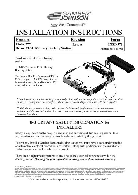
7160-0377 = Recon CF31 Military<br />
Docking Station.<br />
The dock will hold a Panasonic CF30 or<br />
CF31 computer. A CF29 computer can<br />
be mounted with the addition of a .06"<br />
shim under the front hook.<br />
*This document is for the docking station only. For instructions on features, set-up and operation<br />
of the CF31 computer, please refer to the manuals provided by Panasonic with the computer.<br />
** This docking station is designed to be used with a variety of <strong>Gamber</strong>-<strong>Johnson</strong> mounting<br />
systems. <strong>Installation</strong> instructions for other <strong>Gamber</strong>-<strong>Johnson</strong> products are provided with each<br />
individual product.<br />
IMPORTANT SAFETY INFORMATION for<br />
INSTALLERS<br />
Safety is dependent on the proper installation and servicing of this docking station. It is<br />
important to read and follow all instructions before installing this product.<br />
To properly install a <strong>Gamber</strong>-<strong>Johnson</strong> docking station you must have a good understanding<br />
of automotive electrical procedures and systems, along with proficiency in the installation<br />
and service of aftermarket vehicle equipment.<br />
There are no adjustments required at any time of the electrical components within the<br />
docking station. Opening the port replication housing will void the product warranty.<br />
Product Mounting Disclaimer<br />
<strong>Gamber</strong>-<strong>Johnson</strong> is not liable under any theory of contract or tort law for any loss, damage, personal injury, special, incidental or consequential damages for personal injury or other damage<br />
of any nature arising directly or indirectly as a result of the improper installation or use of its products in vehicle or any other application. In order to safely install and use <strong>Gamber</strong>-<strong>Johnson</strong><br />
products full consideration of vehicle occupants, vehicle systems (i.e., the location of fuel lines, brakes lines, electrical, drive train or other systems), air-bags and other safety equipment is<br />
required. <strong>Gamber</strong>-<strong>Johnson</strong> specifically disclaims any responsibility for the improper use or installation of its products not consistent with the original vehicle manufactures specifications<br />
and recommendations, <strong>Gamber</strong>-<strong>Johnson</strong> product instruction sheets, or workmanship standards as endorsed through the <strong>Gamber</strong>-<strong>Johnson</strong> Certified Installer Program.<br />
© copyright 2010 <strong>Gamber</strong>-<strong>Johnson</strong>, LLC<br />
If you need assistance or have questions, call <strong>Gamber</strong>-<strong>Johnson</strong> at 1-800-456-6868
During <strong>Installation</strong><br />
DO NOT connect this docking station to the vehicle battery until:<br />
1. ALL other electrical connections are made<br />
2. Mounting of ALL components is complete<br />
3. VERIFICATION that no shorts exist in the entire system<br />
DO NOT install equipment or route wiring or chords in the deployment path of any<br />
air bag.<br />
When drilling into the vehicle, DO make sure that both sides of the surface are<br />
clear of anything that could be damaged.<br />
It is recommended to install a 32V - 10Amp in-line fuse connected as close to the<br />
battery or power source as possible.<br />
CAUTION: If wiring is shorted to the frame, high current conductors can cause<br />
hazardous sparks resulting in electrical fires or flying molten metal.<br />
After <strong>Installation</strong><br />
Test the docking station to ensure that it is working properly.<br />
File these instructions in a safe place and refer to them when performing<br />
maintenance or re-installing.<br />
WARNING: Failure to follow all safety precautions and instructions may result<br />
in property damage, serious injury or death.<br />
PRE-INSTALLATION RECOMMENDATIONS<br />
Conduct a "Bench Test"<br />
<strong>Gamber</strong>-<strong>Johnson</strong> strongly advises a "bench test" be conducted to verify that all electronic<br />
and software issues are resolved prior to installation:<br />
1. Make sure computer is operational by itself.<br />
2. Insert computer into docking station and verify that the computer is operating in the<br />
dock.<br />
3. Interconnect entire assembly and verify start-up of all components, including other<br />
equipment (printers, modems, scanners, etc.).<br />
*<strong>Gamber</strong>-<strong>Johnson</strong> also recommends positioning of all mounts and equipment in the vehicle<br />
prior to the actual install to verify that mounting locations are safe and practical.
Standard Mounting Hole Locations<br />
A<br />
A<br />
A<br />
2.00<br />
A<br />
A<br />
7.72<br />
2.00<br />
.750 clear<br />
A<br />
A<br />
1.69<br />
SECTION A-A<br />
1/4-20unc x .63 stainless<br />
steel mounting bolts and<br />
lock washers supplied in<br />
hardware bag. Torque to<br />
65-85 in/lbs.<br />
4.094 4.20<br />
A<br />
12.49<br />
1/4-20unc threaded inserts<br />
marked "A" for mounting to<br />
<strong>Gamber</strong> <strong>Johnson</strong> standard<br />
mounting equipment<br />
<strong>Gamber</strong> <strong>Johnson</strong> DS-Clevis mounted<br />
to the rear set of mount holes<br />
(This is the recommended mounting<br />
location because the center of gravity<br />
is centered over the mount)<br />
<strong>Gamber</strong> <strong>Johnson</strong> DS-Clevis mounted<br />
to the front set of mount holes<br />
(Secondary mounting location for use if<br />
vehicle space requires offsetting the dock<br />
over the mount)
Isolator Mounting Hole Locations<br />
B<br />
B<br />
B<br />
2.00<br />
B<br />
B<br />
B<br />
2.00<br />
B<br />
B<br />
B<br />
1.69<br />
2.047<br />
5.00 5.00 1.24<br />
7160-0439<br />
Wire Rope Isolator Assembly<br />
Weight = 3.15 lbs<br />
1/4-20unc threaded inserts marked "B"<br />
for mounting to <strong>Gamber</strong> <strong>Johnson</strong><br />
wire rope isolator assembly<br />
<strong>Gamber</strong> <strong>Johnson</strong> Wire Rope<br />
Isolator Assembly mounted to the<br />
rear set of isolator mounting holes<br />
(This is the recommended mounting<br />
location because the center of gravity<br />
is centered over the mount)<br />
1/4-20unc threaded inserts for mounting<br />
to <strong>Gamber</strong> <strong>Johnson</strong> mounting equipment<br />
<strong>Gamber</strong> <strong>Johnson</strong> Wire Rope<br />
Isolator Assemlby mounted to the<br />
front set of isolator mounting holes<br />
(Secondary mounting location for use if<br />
vehicle space requires offsetting the dock<br />
over the mount)
Dock and Power Supply Dimensions<br />
1.04<br />
11.74<br />
13.66<br />
7160-0377<br />
Recon CF31 Military Docking<br />
Stattion Weight = 11 lbs<br />
5.46<br />
12.49<br />
.88<br />
.31<br />
7.18 1.43<br />
2.33<br />
8.20<br />
10.47<br />
10.00<br />
9.60<br />
4.20<br />
2.44<br />
.91<br />
7.86<br />
J6 - Female connector<br />
(Out-put power to dock)<br />
.62<br />
3.92<br />
1.25<br />
3.00<br />
1.25<br />
6X O .200 mounting holes<br />
Note: mounting hardware<br />
supplied by others<br />
.69 1/4-20unc stainless steel ground stud<br />
(torque nut to 65-85 in/lbs)<br />
1.25<br />
.21<br />
J5 - Male connector<br />
(In-put power from vehicle)<br />
18-32 Vdc Power Supply<br />
Weight = 1.50 lbs
Features<br />
Screen Support<br />
(Shipped unattached - has Option of being<br />
mounted to either side of the dock by customer)<br />
Tethered Connector Cover<br />
(Has option of being relocated to<br />
other side of dock by customer)<br />
Docking Connector<br />
Power Switch<br />
Slide Plate<br />
Hasp for padlock with<br />
9/32" dia. shackle<br />
Note: attach<br />
screen support<br />
and stylus with<br />
hardware found<br />
in hardware bag<br />
7120-0591<br />
Wing Turn Latch<br />
Tethered Stylus<br />
(Shipped unattached - Has option<br />
of being relocated to other side of<br />
dock by customer)<br />
Data Cable Ports<br />
with Lanyard attached Caps<br />
(D38999 Shell Size 13)<br />
Power Cable Port<br />
with Lanyard attached Cap<br />
(D38999 Shell Size 9)<br />
1/4-20unc x .63 Stainless<br />
Steel Ground Stud<br />
(torque nut to 65-85 in/lbs)
Connector Data cables are not supplied with the docking station<br />
15Vdc OUTPUT POWER TO<br />
DOCK<br />
POWER SUPPLY CONNECTORS<br />
18 - 32Vdc INPUT POWER FROM<br />
VEHICLE<br />
NOTES:<br />
1. It is recommended to install a 32V - 10Amp<br />
in-line fuse connected as close to the battery<br />
or power source as possible.<br />
2. The estimated power draw on the 28Vdc<br />
vehicle supply is 3 Amps.<br />
3. MIL STD 461F was achieved by using<br />
completely shielded cables. Cables<br />
containing USB signals must not exceed 5<br />
meters in length.<br />
AMPHENOL CONNECTOR<br />
JD38999/20FA35SN<br />
J6 PIN # J6 SIGNAL<br />
1 PWR_OUT<br />
2 GND<br />
3 GND<br />
4 GND<br />
5 PWR_OUT<br />
6 PWR_OUT<br />
AMPHENOL CONNECTOR<br />
JD38999/20FA35PN<br />
J5 PIN # J5 SIGNAL<br />
1 PWR_IN<br />
2 GND<br />
3 GND<br />
4 GND<br />
5 PWR_IN<br />
6 PWR_IN<br />
J2 = DATA CABLE<br />
AMPHENOL CONNECTOR<br />
#91-569783-35H<br />
(1)VIDEO, (1)AUDIO,<br />
(1)USB ETHERNET<br />
J1 = INPUT POWER<br />
AMPHENOL CONNECTOR<br />
#91-569781-35G<br />
J1 PIN # J1 SIGNAL<br />
1 PWR_IN<br />
2 GND<br />
3 GND<br />
4 GND<br />
5 PWR_IN<br />
6 PWR_IN<br />
J2 PIN # J2 SIGNAL<br />
1 VSYNC<br />
2 HSYNC<br />
3 DDC2BD<br />
4 NC<br />
5 SYNC_GND<br />
6 +5V_VIDEO<br />
7 CRTB_GND<br />
8 CRTG_GND<br />
9 CRTR_GND<br />
10 GND<br />
11 NC<br />
12 CRTB<br />
13 CRTG<br />
14 CRTR<br />
15 USB_RXP<br />
16 USB_TXN<br />
17 USB_TXP<br />
18 HP_R<br />
19 HP_L<br />
20 AGND<br />
21 DDC2BC<br />
22 USB_RXN
Connector Data cables are not supplied with the docking station<br />
MIL STD 461F was achieved by using completely shielded cables. Cables<br />
containing USB signals must not exceed 5 meters in length.<br />
J3 = DATA CABLE<br />
AMPHENOL CONNECTOR<br />
#91569783-35J<br />
(2) USB, (1) TRUE ETHERNET,<br />
(2) 5 Vdc POWER OUTPOUTS<br />
J3 PIN# J3 SIGNAL<br />
1 PPTMDI2-<br />
2 PPTMDI2+<br />
3 PPTMDI1-<br />
4 PPTMDI1+<br />
5 PPTMDI0-<br />
6 PPTMDI0+<br />
7 USB4_GND<br />
8 USBDP4<br />
9 USBDM4<br />
10 USB4_PWR<br />
11 USB3_GND<br />
12 USBDP3<br />
13 USBDM3<br />
14 USB3_PWR<br />
15 +5V_GND<br />
16 +5VDC<br />
17 +5VDC<br />
18 NC<br />
19 NC<br />
20 PPTMDI3-<br />
21 PPTMDI3+<br />
22 +5V_GND<br />
J4 = DATA CABLE<br />
AMPHENOL CONNECTOR<br />
#91-569783-35S<br />
(2) SERIAL, & (1) USB<br />
J4 PIN # J4 SIGNAL<br />
1 GND<br />
2 DTR2<br />
3 SOUT2<br />
4 SIN2<br />
5 DCD2<br />
6 RI1<br />
7 CTS1<br />
8 R TS1<br />
9 DSR1<br />
10 GND<br />
11 DTR1<br />
12 SOUT1<br />
13 SIN1<br />
14 DCD1<br />
15 USBDP2<br />
16 USBDM2<br />
17 USB2_PWR<br />
18 RI2<br />
19 CTS2<br />
20 RTS2<br />
21 DSR2<br />
22 USB2_GND
1. J1 pins 1, 5 and 6 = Input Power (+28Vdc)<br />
2. J1 pins 2, 3 and 4 = Input Power Ground<br />
Pin Acronyms List for 7160-0377<br />
3. J2 pins 1-14 and 21 = Video Output<br />
4. J2 pins 15-17 and 22 = USB/Ethernet Output<br />
a. USB_TXN = Transmit Data Negative Signal<br />
b. USB_TXP = Transmit Data Plus Signal<br />
c. USB_RXN = Receive Data Negative Signal<br />
d. USB_RXP = Receive Data Plus Signal<br />
5. J2 pins 18-20 = Audio Output<br />
a. HP_R = Headphone Right Audio Output<br />
b. HP_L = Headphone Left Audio Output<br />
c. AGND = Audio Ground<br />
6. J3 pins 1-6 and 20-21 = 1GHz Ethernet<br />
a. PPTMDI2- = Bi-Directional pair 2- or C- (J3-1)<br />
b. PPTMDI2+ = Bi-Directional pair 2+ or C+ (J3-2)<br />
c. PPTMDI1- = Bi-Directional pair 1- or B- (J3-3)<br />
d. PPTMDI1+ = Bi-Directional pair 1+ or B+ (J3-4)<br />
e. PPTMDI0- = Bi-Directional pair 0- or A- (J3-5)<br />
f. PPTMDI0+ = Bi-Directional pair 0+ or A+ (J3-6)<br />
g. PPTMDI3- = Bi-Directional pair 3- or D- (J3-20)<br />
h. PPTMDI3+ = Bi-Directional pair 3+ or D+ (J3-21)<br />
7. J3 pins 7-10 = USB Port<br />
a. USB4_PWR = USB #4 Port +5Vdc<br />
b. USBDP4 = USB #4 Port Data +<br />
c. USBDM4 = USB #4 Port Datad.<br />
USB4_GND = USB #4 Port Ground<br />
8. J3 pins 11-14 = USB Port<br />
a. USB3_PWR = USB #3 Port +5Vdc<br />
b. USBDP3 = USB #3 Port Data +<br />
c. USBDM3 = USB #3 Port Datad.<br />
USB3_GND = USB #3 Port Ground<br />
9. J3 pins 15-17 and 22 = Auxiliary +5Vdc Output max 4 amps<br />
a. +5VDC = +5 Volts Output (J3-16 & 17) (4 Amps max when combined)<br />
b. +5VDC_GND = +5 Volts Output Return (J3-15 & 22)<br />
10. J4 pins 1-5 and 18-21 = Serial Port #2<br />
11. J4 pins 6-14 = Serial Port #1<br />
12. J4 pins 15-17 and 22 = USB Port<br />
a. USB2_PWR = USB #2 Port +5Vdc<br />
b. USBDP2 = USB #2 Port Data +<br />
c. USBDM2 = USB #2 Port Datad.<br />
USB2_GND = USB #2 Port Ground
Installing the CF31<br />
computer into the dock<br />
Step 1: Make sure the sliding door, located on the back surface<br />
of the computer, has been opened to expose the computers'<br />
docking connector.<br />
Step 2: Make sure the power switch on the dock is in the "OFF"<br />
position. Panasonic does not recomend "Hot-Docking" the<br />
Toughbook computers.<br />
Make sure no loose or foreign objects are on the surface of the<br />
dock, the connector cover is mounted in the storage location on<br />
the side of the dock, and the slide plate is in the forward<br />
location.<br />
Step 3: Place the front edge of the computer into the dock. The<br />
pocket on the front edge of the computer will fit onto the hook on<br />
the front edge of the dock.<br />
Step 4: Lower the back edge of the computer down onto the slide<br />
plate and guide pins.<br />
Step 5: Push the slide plate with computer, back onto the docking<br />
connector.<br />
Step 6: Rotate the wing turn compression latch 180 degrees<br />
clockwise. The alignment marks on the latch will align when the<br />
latch is in the compressed state. A padlock with a 9/32" diameter<br />
shackle can be used to help secure the computer to the docking<br />
station.<br />
Step 7: Turn "ON" the power switch on the dock to connect power<br />
to the unit.


