THERMAL IMAGING GUIDEBOOK FOR ... - Proffsmagasinet
THERMAL IMAGING GUIDEBOOK FOR ... - Proffsmagasinet
THERMAL IMAGING GUIDEBOOK FOR ... - Proffsmagasinet

You also want an ePaper? Increase the reach of your titles
YUMPU automatically turns print PDFs into web optimized ePapers that Google loves.
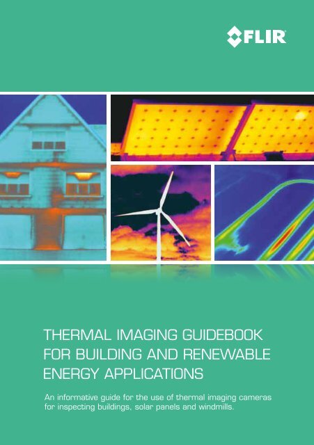
<strong>THERMAL</strong> <strong>IMAGING</strong> <strong>GUIDEBOOK</strong><br />
<strong>FOR</strong> BUILDING and renewable<br />
energy APPLICATIONS<br />
An informative guide for the use of thermal imaging cameras<br />
for inspecting buildings, solar panels and windmills.
Content<br />
1. The thermal imaging camera and how it works 8<br />
2. Why use thermal imaging 10<br />
3. Using thermal imaging for building applications 14<br />
4. Thermal physics for building applications 26<br />
5. Thermal imaging cameras for inspecting solar panels 32<br />
6 Inspecting wind turbines with thermal imaging cameras 44<br />
7. Choosing the right thermal imaging camera supplier 48<br />
8. Finding the best solution 50<br />
9. How to carry out thermal inspections 62<br />
This booklet is produced in close cooperation with the Infrared Training Center (ITC).<br />
All images used are for illustrative purposes only.<br />
SPECIFICATIONS ARE SUBJECT TO CHANGE WITHOUT NOTICE © Copyright 2011, FLIR Systems AB.<br />
All other brand and product names are trademarks of their respective owners.<br />
3
Introduction<br />
The first commercial thermal imaging camera was sold in 1965<br />
for high voltage power line inspections, by what would later<br />
become FLIR Systems.<br />
Since then thermal imaging technology has evolved. Thermal<br />
imaging cameras have become compact systems that look just<br />
like a digital video camera or digital photo camera. They are easy<br />
to use and generate crisp real-time high-resolution images.<br />
One of the sectors that rapidly discovered that thermal imaging<br />
can provide valuable information that is practically impossible<br />
to capture with any other tool is the building industry. From an<br />
exotic technology, thermal imaging cameras have evolved to a<br />
widespread tool that is used by numerous building inspectors<br />
worldwide.<br />
A thermal imaging camera is a unique tool to map the energy<br />
loss from a building. This method is quick and the thermal<br />
images which the camera produces provide a precise and<br />
convincing argumentation.<br />
The use of a thermal imaging camera – either as a standalone<br />
tool or in combination with other methods such as ‘BlowerDoor’<br />
systems – speeds up the work considerably. Thermal imaging<br />
pinpoints exactly where the energy losses are without the use of<br />
any destructive testing methods.<br />
Thermal imaging cameras have strongly evolved over the last 50 years. FLIR Systems has always been a thermal imaging pioneer that<br />
brings the most advanced thermal imaging cameras to the market.<br />
4
A thermal imaging camera is a reliable non contact instrument<br />
which is able to scan and visualize the temperature distribution<br />
of entire surfaces quickly and accurately. Thermography<br />
programs have contributed to substantial cost savings around<br />
the world.<br />
Thermal imaging for the building industry<br />
Since the 1970s we have become increasingly conscious that<br />
energy resources are precious and limited.<br />
The building sector accounts for 40% of the EU’s energy<br />
requirements and offers the largest single potential for energy<br />
efficiency. Due to the huge potential the European Commission<br />
has formed a directive for energy performance regulation of<br />
buildings on which many national laws are already based.<br />
Thousands of European businesses are already affected while<br />
the Energy Performance Certificates (EPCs) have become<br />
mandatory in many countries in the EU for new buildings and<br />
building refurbishments.<br />
This, together with recent economic stimulus packages in many<br />
countries, is likely to drive up the demand for air tightness<br />
testing and other methods for energy efficiency investigation.<br />
In a longer perspective we are likely to see harsher EU directives<br />
for energy savings in buildings. This will have great impact on<br />
many professionals working in the building sector.<br />
Modern thermal imaging cameras are small, lightweight and easy to use.<br />
5
Renewable energies<br />
The fact that traditional energy sources like coal, gas and oil are<br />
scarce has also led to rising prices. Furthermore, awareness has risen<br />
that we cannot keep polluting our planet using these fossil fuels.<br />
Solar<br />
Solar panels can convert the sun’s energy into electricity. And into<br />
hard cash. To receive maximum returns and high yields for decades<br />
however, high quality is key. The solar module, the most important<br />
part of a solar system, must be reliable and able to continue<br />
producing electricity for years at an end. To ensure good quality during<br />
the full lifetime cycle of a solar module, thermal imaging cameras can<br />
play an important role.<br />
The use of thermal imaging cameras for solar panel evaluation offers several advantages. Anomalies can<br />
clearly be seen on a crisp thermal image and - unlike most other methods - thermal cameras can be used<br />
to scan installed solar panels during normal operation.<br />
As fossil fuel reserves dwindle, the prices for coal and gas rise<br />
to new heights and many people look to the sun for a renewable<br />
power source. But solar panels are susceptible to wear. Building<br />
professionals all over the world therefore use thermal imaging<br />
cameras to inspect solar panels installed on rooftops or in solar parks.<br />
6
Wind<br />
Another renewable energy source is wind. All over the world,<br />
windmills are becoming increasingly popular for generating<br />
electricity. Entire wind parks are being installed both on land and<br />
off shore.<br />
A windmill contains a lot of mechanical and electrical<br />
components that can easily be checked with a thermal imaging<br />
camera. Correct maintenance inspections of all parts of a<br />
windmill ensure that they will keep generating electricity for<br />
many years to come.<br />
A thermal image of a wind turbine taken from ground level<br />
This booklet is an in-depth guide for building, solar panel and<br />
windmill inspections using a thermal imaging camera. There are<br />
many details to pay attention to when carrying out a thermal<br />
inspection. As well as knowing how the thermal camera works<br />
and how to take images, it is important to know the physics<br />
behind the thermal patterns of a building, solar panel or windmill,<br />
and how they are constructed. All of this has to be taken into<br />
consideration to understand, interpret and judge thermal images<br />
correctly.<br />
It is impossible, however, to cover all principles, concepts and<br />
use of systems for analysis of these types of applications in this<br />
guidebook. That is why FLIR Systems offers training courses in<br />
cooperation with the Infrared Training Center (ITC) specifically<br />
designed for building applications.<br />
This guidebook will present<br />
• Thermal imaging applications<br />
• How the thermal imaging camera works and what to<br />
consider when purchasing a camera<br />
• Comprehensive advice on how to conduct thermographic<br />
surveys<br />
7
The thermal imaging camera<br />
and how it works<br />
A thermal imaging camera records the intensity of radiation in the<br />
infrared part of the electromagnetic spectrum and converts it to a visible<br />
image.<br />
Sir William Herschel discovered infrared radiation in 1800.<br />
What is infrared<br />
Our eyes are detectors that are designed to detect electromagnetic<br />
radiation in the visible light spectrum. All other forms of electromagnetic<br />
radiation, such as infrared, are invisible to the human eye.<br />
The existence of infrared was discovered in 1800 by astronomer Sir<br />
Frederick William Herschel. Curious to the thermal difference between<br />
different light colors, he directed sunlight through a glass prism to create<br />
a spectrum and then measured the temperature of each color. He found<br />
that the temperatures of the colors increased from the violet to the red<br />
part of the spectrum.<br />
After noticing this pattern Herschel decided to measure the temperature<br />
just beyond the red portion of the spectrum in a region where no sunlight<br />
was visible. To his surprise, he found that this region had the highest<br />
temperature of all.<br />
8
Infrared radiation lies between the visible and microwave portions of<br />
the electromagnetic spectrum. The primary source of infrared radiation<br />
is heat or thermal radiation. Any object that has a temperature above<br />
absolute zero (-273.15 degrees Celsius or 0 Kelvin) emits radiation in the<br />
infrared region. Even objects that we think of as being very cold, such as<br />
ice cubes, emit infrared radiation.<br />
Gamma<br />
Rays<br />
X-Rays<br />
Ultra-<br />
Violet<br />
Visible<br />
Infrared<br />
Microwaves<br />
UHF<br />
Radio<br />
VHF<br />
Visible<br />
Infrared<br />
MW<br />
LW<br />
2 5 8 14 micrometers<br />
We experience infrared radiation every day. The heat that we feel from<br />
sunlight, a fire or a radiator is all infrared. Although our eyes cannot see<br />
it, the nerves in our skin can feel it as heat. The warmer the object, the<br />
more infrared radiation it emits.<br />
The thermal imaging camera<br />
Infrared energy (A) coming from an object is focused by the optics (B)<br />
onto an infrared detector (C). The detector sends the information to<br />
sensor electronics (D) for image processing. The electronics translate the<br />
data coming from the detector into an image (E) that can be viewed in<br />
the viewfinder or on a standard video monitor or LCD screen.<br />
E<br />
A B C D<br />
E<br />
Infrared thermography is the art of transforming an infrared image into<br />
a radiometric one, which allows temperature values to be read from the<br />
image. So every pixel in the radiometric image is in fact a temperature<br />
measurement. In order to do this, complex algorithms are incorporated<br />
into the thermal imaging camera.<br />
9
Why use thermal imaging<br />
Thermal imaging cameras for building applications are powerful<br />
and non invasive tools for monitoring and diagnosing the condition<br />
of buildings, solar panels and windmills. With a thermal imaging<br />
camera you can identify problems early, allowing them to be<br />
documented and corrected before becoming more serious and<br />
more costly to repair.<br />
FLIR thermal imaging cameras:<br />
• Are as easy to use as a camcorder or a digital camera<br />
• Give you a full image of the situation<br />
• Identify and locate the problem<br />
• Measure temperatures<br />
• Store information<br />
• Tell you exactly what needs to be fixed<br />
• Help you find faults before real problems occur<br />
• Save you valuable time and money<br />
Defects in photovoltaic cells.<br />
Thermal inspection of a<br />
window installation.<br />
Heated pavement, but only<br />
a part of it is working.<br />
FLIR Systems offers a wide range of thermal imaging cameras.<br />
Whether you use thermal imaging for an inspection of large<br />
buildings or for a domestic residence, FLIR will have just the right<br />
thermal imaging camera for you.<br />
10
Why use thermal imaging cameras<br />
Why would you choose a FLIR thermal imaging camera There are<br />
other technologies available to help you measure temperatures in a<br />
non-contact mode. Infrared thermometers for example.<br />
Infrared thermometers - thermal imaging cameras<br />
Infrared (IR) thermometers are reliable and very useful for singlespot<br />
temperature readings, but when scanning large areas, it’s<br />
easy to miss critical parts like air leakages, areas with insufficient<br />
insulation or water intrusion. A FLIR thermal imaging camera can<br />
scan entire buildings, heating and HVAC installations. It never<br />
misses a potential problem area no matter how small this might be.<br />
IR thermometer, temperature<br />
measurement in one spot<br />
FLIR i3, temperature in 3,600 spots<br />
Find problems faster and easier with extreme accuracy<br />
It is easy to miss a critical building problem if you are only using a<br />
spot IR thermometer. A FLIR thermal imaging camera will give you<br />
a total view of the situation and instant diagnostic insights. It not<br />
only locates a construction problem in a building but shows the full<br />
extent of problems.<br />
11
Use thousands of infrared thermometers at the same time<br />
With an infrared thermometer you are able to measure the<br />
temperature at one single spot. FLIR thermal imaging cameras<br />
can measure temperatures on the entire image. The FLIR i3 has<br />
an image resolution of 60 x 60 pixels. This means that it is equal<br />
to using 3,600 IR thermometers at the same time. If we look at<br />
the FLIR P660, our top model, which has an image resolution<br />
of 640 x 480 pixels, this means 307,200 pixels or using 307,200<br />
infrared thermometers at the same time.<br />
What an IR Thermometer sees.<br />
What a thermal imaging camera<br />
sees.<br />
What an IR Thermometer sees.<br />
What a thermal imaging camera<br />
sees.<br />
What an IR Thermometer sees.<br />
What a thermal imaging camera<br />
sees.<br />
12
Using thermal imaging<br />
for building applications<br />
Inspecting buildings using a thermal imaging camera is a powerful<br />
and non invasive means of monitoring and diagnosing the condition<br />
of buildings. Thermal imaging technology has become one of the<br />
most valuable diagnostic tools for building inspections. A thermal<br />
imaging camera can identify problems early, allowing them to be<br />
documented and corrected before becoming more serious and more<br />
costly to repair.<br />
A building diagnostics inspection with a thermal imaging camera can<br />
help:<br />
• Visualize energy losses<br />
• Detect missing or defective insulation<br />
• Source air leaks<br />
• Find moisture in insulation, in roofs and walls, both in the<br />
internal and the external structure<br />
• Detect mold and badly insulated areas<br />
• Locate thermal bridges<br />
• Locate water infiltration in flat roofs<br />
• Detect breaches in hot-water pipes<br />
• Detect construction failures<br />
• Monitor the drying of buildings<br />
• Find faults in supply lines and district heating<br />
• Detect electrical faults<br />
Thermal imaging cameras are the perfect tool for locating and<br />
identifying building failures because they make the invisible visible.<br />
On a thermal image problems seem to jump right out at you. A<br />
thermal imaging camera is the one tool that really lets you SEE it all.<br />
A thermal image that includes accurate temperature data provides<br />
building experts with important information about the insulation<br />
conditions, moisture ingress, mold development, electrical faults, the<br />
presence of thermal bridges and the conditions of HVAC systems.<br />
Thermal imaging cameras are such a valuable and versatile tool that<br />
it is not possible to list all the applications. New and innovative ways<br />
of using the technology are being developed every day. Some of the<br />
many ways in which thermal imaging cameras can be used within<br />
the range of building related applications are explained in this section<br />
of the guide.<br />
14
Insulation defects and air leaks<br />
Thermal imaging is an outstanding tool to locate building<br />
defects such as missing insulation, delaminating render and<br />
condensation problems.<br />
This building is warmer on the inside. It is a sandwich construction, concrete - insulation -<br />
concrete. One section of insulation is missing which is not possible to see visually either<br />
from the inside or the outside. Here thermal imaging can see what the human eye can’t.<br />
Framework construction. Many of the sections are missing insulation as indicated<br />
by the warmer colors.<br />
Glass roof above an atrium. It is watertight, but not air tight. Warm air escapes<br />
because of the over pressure.The solution is to air tighten the glass roof.<br />
15
Warehouses with well insulated prefabricated walls and roof can<br />
experience energy loss from the joints between these parts.<br />
A warehouse with a lot of warm air escaping between the wall and the roof. These<br />
joints should be tightened to stop the energy loss.<br />
When using a thermal imaging camera to find missing insulation<br />
or energy losses, the difference in temperature between the<br />
inside of the building and the outside should be preferably at<br />
least 10 °C. When using a thermal imaging camera with a high<br />
image resolution and high thermal sensitivity the temperature<br />
difference can be less.<br />
In cold climates, buildings are often inspected during winter time.<br />
In hotter climates, where it is important to see that the building<br />
is well insulated in order to keep the cool air that is generated by<br />
HVAC systems inside, the summer months can be ideal for this<br />
type of thermal inspections.<br />
Missing insulation in parts of the wall.<br />
Thermal survey from outside, the thermal images clearly indicate poor or missing<br />
insulation.<br />
16
The thermal image clearly shows insufficient insulation in the wall below the<br />
window.<br />
Detection of air leaks<br />
Air leaks lead to higher energy consumption and often cause<br />
problems with the ventilation system. Air leaks can also lead to<br />
condensation in the construction which in its turn can cause a poor<br />
indoor climate.<br />
To detect air leaks with a thermal imaging camera a temperature<br />
difference and a pressure difference is needed.<br />
With a thermal imaging camera you detect the characteristic<br />
patterns that occur when cold air is coming through a leak in the<br />
construction, goes along a surface and cools the surface down.<br />
The thermal inspection should always take place on the side of the<br />
construction with negative pressure. Air leaks are often detected<br />
with the help of the pressurization method, often referred to as the<br />
"BlowerDoor" test. More information about "BlowerDoor" tests can<br />
be found further on in this booklet.<br />
Image shows air leaks between the ceiling and the window.<br />
17
Moisture Detection<br />
Moisture damage is the most common form of deterioration for<br />
a building. Air leakage can cause condensation to form within<br />
walls, floors, or ceilings. Wet insulation takes a long time to dry<br />
and becomes a prime location for mold and fungi.<br />
Scanning with a thermal imaging camera can locate moisture<br />
that creates an environment conductive to mold. One might<br />
smell its presence, but not know where it is forming. A thermal<br />
survey will determine where moist areas are located that can<br />
lead to serious mold which can lead to health issues.<br />
Moisture intrusion in floor, impossible to see with the human eye, but clearly visible<br />
on the thermal image.<br />
Moisture can be difficult to spot and the trick is to make the<br />
construction change temperature. Materials with moisture will then<br />
be clearly visible as they change temperature much slower than dry<br />
materials. Where other methods only measure the temperature in<br />
one spot, thermal imaging cameras can scan an entire area rapidly.<br />
18<br />
Thermal images taken of the same ceiling. In the left image the room temperature<br />
has been changed quickly by heating the room which makes the moisture clearly<br />
visible on the thermal image.
Thermal Bridges<br />
Other applications include the location of thermal bridges, which<br />
indicate spots in a building where energy is being wasted.<br />
A thermal bridge is an area where the building envelope<br />
has a lower thermal resistance. It is caused by construction<br />
constraints. Heat will follow the easiest path from the heated<br />
space to the outside - the path with the least resistance.<br />
Typical effects of thermal bridges are:<br />
• Decreased interior surface temperatures; in the worst cases<br />
this can result in condensation problems, particularly at corners.<br />
• Significantly increased heat losses.<br />
• Cold areas in buildings.<br />
The image shows a thermal bridge at one of the floors.<br />
The thermal image shows thermal bridges between the roof beams and<br />
adjacent walls.<br />
19
Supply lines and district heating<br />
In cold climates, pavements and parking areas are sometimes<br />
heated.<br />
District heating systems distribute heat, often steam, that is<br />
generated in a centralized location for residential and<br />
commercial heating requirements.<br />
A thermographic survey can easily detect defects in pipes or<br />
tubes of any underground heating system. A thermal imaging<br />
camera can help to identify the exact location of the defect so<br />
that repair works can be minimized.<br />
Defects in district heating systems can be easily located with a thermal imaging<br />
camera.<br />
A thermal image, taken from the air, identifies leaks or insulation failure in the district<br />
heating system<br />
20
Finding water infiltration in flat roofs<br />
Thermal imaging is also used to detect water infiltration in flat<br />
roofs.<br />
Water retains heat longer than the rest of the roofing material<br />
and can easily be detected with a thermal imaging camera<br />
very late in the evening or at night after the rest of the roof has<br />
cooled down.<br />
Tremendous savings can be made by repairing wet areas rather<br />
than replacing the entire roof.<br />
Water infiltration in flat roofs.<br />
21
Locating leaks in floor heating<br />
Thermal imaging is an easy-to-use tool to find and check pipes<br />
and tubes for leaks, even when the water pipes are laid in the<br />
floor or under plaster. The heat of the pipes radiates through the<br />
surface and the pattern can be easily detected with a thermal<br />
imaging camera.<br />
The thermal image shows a leak in an underfloor heating system.<br />
Underfloor heating problems can easily be detected with a thermal imaging<br />
camera.<br />
22
Quality assurance<br />
Thermal imaging technology is also used for quality assurance<br />
and the inspection of new buildings.<br />
During construction-drying, thermal images make it possible<br />
to determine the progress of the drying procedures so that<br />
necessary measures can be taken to speed up the drying<br />
process.<br />
If this process can be accelerated and it can be proven, with the<br />
help of a thermal imaging camera, that the construction is totally<br />
dry, the building can be surrendered faster to the client.<br />
Building renovations<br />
Thermal imaging provides valuable information during<br />
the renovation of buildings and monuments. Framework<br />
constructions hidden by mineral plaster can become clearly<br />
visible in a thermal image. It can then be decided whether<br />
exposure of these structures is useful. The detachment of plaster<br />
from walls can also be located in a very early stage so that<br />
preservation measures can be taken.<br />
Thermal imaging makes underlying structures clearly visible.<br />
23
Plumbing<br />
Thermal imaging is a perfect tool to detect blocked or broken<br />
pipes and other plumbing relates issues. Even if the pipes<br />
are laid under the floor or inside a wall it can be possible to<br />
determine the exact location of the problem by having hot water<br />
flowing through the pipes. The heat will radiate and the problem<br />
area will become clearly visible on a thermal image.<br />
Detect plumbing problems with thermal imaging.<br />
HVAC installations<br />
Heating, Ventilation and Air-Conditioning (HVAC) systems need<br />
to be well maintained. They need to deliver air at the correct<br />
humidity and temperature and filter any indoor pollutants.<br />
Thermal imaging can help to determine whether HVAC systems<br />
are operating properly. When working incorrectly they can cause<br />
poor indoor air quality.<br />
24
Electrical faults<br />
Every building also contains a lot of electrical installations.<br />
Thermal imaging can also be used to scan electrical cabinets,<br />
fuses, connections, etc.<br />
By detecting problems that are invisible to the naked eye the<br />
problem can be repaired. If left unchecked, electrical problems<br />
can cause high temperatures. Furthermore, sparks can fly which<br />
might set the surroundings on fire.<br />
For more information about checking electrical systems with<br />
a thermal imaging camera, please read the "Thermal imaging<br />
guidebook for industrial applications".<br />
One of the fuses is overheated, a potential fire risk.<br />
25
Thermal physics<br />
for building applications<br />
In order to interpret the thermal images correctly the operator<br />
needs to know how different materials and circumstances<br />
influence the temperature readings from the thermal imaging<br />
camera. Some of the most important factors influencing the<br />
temperature readings are:<br />
1. Thermal conductivity<br />
Different materials have different thermal properties. Insulation<br />
tends to warm up slowly, while metals tend to warm up quickly.<br />
This is called thermal conductivity. Difference in thermal properties<br />
in two different materials can lead to large temperature differences<br />
in certain situations.<br />
2. Emissivity<br />
To read correct temperatures, one important thing needs to be<br />
taken into account, and that is a factor known as emissivity.<br />
Emissivity is the efficiency with which an object emits infrared<br />
radiation. This is highly dependent on material properties.<br />
If you look at the thermal image you might think that the gold paint is colder<br />
than the mug surface. In reality they have exactly the same temperature,<br />
the difference in intensity of infrared radiation is caused by a difference in<br />
emissivity.<br />
It is extremely important to set the right emissivity in the camera<br />
or the temperature measurements will be incorrect. FLIR Systems<br />
thermal imaging cameras have predefined emissivity settings for<br />
lots of materials, and the rest can be found in an emissivity table.<br />
26
The thermal image on the left has the right emissivity settings for human skin<br />
(0.97) and the temperature reading shows the correct temperature (36.7 °C).<br />
For the thermal image on the right, the wrong emissivity was entered (0.15),<br />
leading to a false temperature reading (98.3 °C).<br />
3. Reflection<br />
Some materials, such as most metals, reflect thermal radiation<br />
much like a mirror reflects visible light. Reflections can lead to<br />
misinterpretation of the thermal image; the reflection of thermal<br />
radiation from the operator’s own body or from a light bulb<br />
might lead to a false temperature reading. The operator should<br />
therefore choose the angle at which the thermal imaging camera<br />
is pointed at the object carefully, to avoid such reflections.<br />
The window reflects thermal radiation, so to a thermal imaging camera<br />
the window acts as a mirror.<br />
If the object’s surface material has a low emissivity and there<br />
is a large difference in temperature between the object and the<br />
ambient temperature, the reflection of incident radiation will<br />
influence the temperature readings from the thermal imaging<br />
camera. To solve this problem FLIR has included the option<br />
in its thermal imaging cameras to set the apparent reflected<br />
temperature.<br />
27
4. Indoor and outside temperatures<br />
To detect missing or ill performing insulation using thermal imaging<br />
cameras there needs to be a difference between the temperature<br />
indoors and the temperature outside. It is often possible to do work<br />
with smaller temperature differences, but usually a temperature<br />
difference of at least 10 °C between the two sides of the wall is<br />
advisable.<br />
Such inspections are typically done from both the inside and the<br />
outside. Missing, damaged or non-performing insulation will stand out<br />
clearly if the temperature difference is sufficient.<br />
The user should know the indoor- and outdoor temperature and also<br />
needs to know if there have been big temperature changes during the<br />
last 24 hours.<br />
5. Influences on the outside of a building<br />
It probably goes without saying that direct sunlight can influence<br />
thermal readings, but sunlight can have long lasting effects as well.<br />
Direct sunlight and shadows might even influence the thermal pattern<br />
on a surface many hours after the exposure to sunlight has ended.<br />
Differences in thermal conductivity can also cause differences in<br />
thermal patterns. Brick changes temperature much slower than wood,<br />
for example. Wind can also influence the thermal data. Airflows cool<br />
down the surface material, lowering the temperature differences<br />
between hot and cold areas.<br />
Another obvious factor that can render thermal imaging inspection<br />
useless is rain, since it lowers the surface temperatures. Even after<br />
the rain has stopped the evaporation of the water cools down the<br />
material’s surface. Obviously this can lead to misleading thermal<br />
patterns.<br />
6. Heating and ventilation systems<br />
External influences on surface temperatures can also be found indoors.<br />
Ambient temperature can influence the object surface temperature,<br />
but there’s another factor as well: climate control. Heating systems<br />
create temperature differences that can cause misleading thermal<br />
patterns. Cool air flowing from ventilators or air conditioning systems<br />
can have the opposite effect, cooling down the surface.<br />
28
7. Influences on the inside of the building<br />
Bookshelves, cabinets and pictures hanging on the wall can also<br />
change the thermal pattern. These examples of furniture and wall<br />
decorations have an insulating effect. If these things are taken away<br />
from the wall, that area of the wall will show up in the thermal image<br />
as being colder. This might be confused for missing insulation. For<br />
that reason it is advisable to remove items from the wall at least 6<br />
hours before inspection.<br />
These two thermal images are taken of the same wall. The temperature outside is<br />
colder than inside. The image to the right shows what can happen when you take<br />
away a picture from the wall. The cold area behind the picture has the same size as<br />
the area between two studs in the wall, it looks like some insulation is missing in<br />
the wall.<br />
8. Reflections from the surroundings<br />
When scanning reflective targets, be sure to change your angle to<br />
minimize the reflections on the image. The reflection could be from<br />
your body heat, or some other heat source in the area, a piece of<br />
machinery, light bulb or a transformer. Reflections will give you incorrect<br />
data in the thermal image, and if not understood, it is a data error.<br />
The image shows reflections on an inner wall (to the right) caused by the window<br />
to the left.<br />
29
9. Type of materials used in the construction<br />
Some materials, for example concrete, are thermally slow which<br />
mean they change temperature very slowly. Other materials, like<br />
most metals, change temperature quickly. In order to interpret<br />
the results correctly, the thermographer has to know if there<br />
has been any big temperature change outside or inside before<br />
the inspection takes place – as this can affect the temperature<br />
readings.<br />
10. How the construction is built<br />
An outer wall can be built with an air gap between the outer skin<br />
and the rest of the construction. Such type of construction is not<br />
suitable for control from the outside. Any framework in the wall<br />
construction becomes colder seen from the inside (provided it’s<br />
warmer inside). From the cold side it is the opposite situation.<br />
These are expected characteristic patterns and there is nothing<br />
wrong.<br />
Thermal image taken from the inside. The framework is visible, and so are the<br />
screws fitting the sheet covering to the framework. The corner is clearly colder,<br />
called a corner-effect, but there is nothing wrong here.<br />
30
Thermal imaging cameras for<br />
inspecting solar panels.<br />
Renewable energies<br />
The fact that traditional energy sources like coal, gas and oil are<br />
scarce has led to high prices. Furthermore, awareness has risen<br />
that we cannot keep polluting our planet using these fossil fuels.<br />
With solar panels on your roof you can convert the sun’s energy<br />
into electricity and into hard cash. Solar power can be a lucrative<br />
investment. To receive maximum return and high yields for<br />
decades however, high quality is key. The solar module is the<br />
most important part of a solar system. It must be reliable and<br />
able to continue producing electricity for years at an end. To<br />
ensure reliable operation during the full lifetime cycle of a solar<br />
module, thermal imaging cameras can play an important role.<br />
As fossil fuel reserves dwindle, the prices for coal and gas rise<br />
to new heights and many people look to the sun for a renewable<br />
power source. But solar panels are susceptible to wear. Building<br />
professionals all over the world therefore use thermal imaging<br />
cameras to inspect solar panels installed on rooftops or in solar<br />
parks.<br />
Inspecting solar panels<br />
The use of thermal imaging cameras for solar panel evaluation<br />
offers several advantages. Anomalies can clearly be seen on a<br />
crisp thermal image and - unlike most other methods – thermal<br />
imaging cameras can be used to scan installed solar panels<br />
during normal operation. Finally, thermal imaging cameras also<br />
allow to scan large areas within a short time frame.<br />
32
With a thermal imaging camera, potential problem areas can be<br />
detected and repaired before actual problems or failures occur.<br />
But not every thermal imaging camera is suited for solar cell<br />
inspection, and there are some rules and guidelines that need<br />
to be followed in order to perform efficient inspections and to<br />
ensure that you draw correct conclusions.<br />
These red spots indicate modules<br />
that are consistently hotter than the<br />
rest, indicating faulty connections.<br />
This hot spot within one solar cell<br />
indicates physical damage within the<br />
cell.<br />
Procedures for inspecting solar panels with thermal imaging<br />
cameras<br />
To achieve sufficient thermal contrast when inspecting solar<br />
cells in the field, a solar irradiance of 500 W/m 2 or higher is<br />
needed. For the maximum result a solar irradiance of 700 W/m 2<br />
is advisable. The solar irradiance describes the instantaneous<br />
power incident on a surface in units of kW/m 2 , which can<br />
be measured with either a pyranometer (for global solar<br />
irradiance) or a pyrheliometer (for direct solar irradiance). It<br />
strongly depends on location and local weather. Low outside<br />
temperatures may also increase thermal contrast.<br />
This thermal image shows an example<br />
of the so-called ‘patchwork pattern’,<br />
which indicates that this panel has a<br />
defective bypass diode.<br />
This thermal image shows a hot spot<br />
due to cell breakage in a standard 60<br />
cell module.<br />
33
What type of camera do you need<br />
Handheld thermal imaging cameras for building inspections<br />
typically have an uncooled micro bolo meter detector sensitive<br />
in the 8 – 14 μm waveband. However, glass is not transparent<br />
in this region. When solar cells are inspected from the front, a<br />
thermal imaging camera sees the heat distribution on the glass<br />
surface but only indirectly the heat distribution in the underlying<br />
cells. Therefore, the temperature differences that can be<br />
measured and seen on the solar panel’s glass surface are small.<br />
In order for these differences to be visible, the thermal imaging<br />
camera used for these inspections needs a thermal sensitivity<br />
≤0.08 ºC. To clearly visualize small temperature differences<br />
in the thermal image, the camera should also allow manual<br />
adjustment of the level and span.<br />
Thermal image with level and span in automatic mode (left) and manual mode<br />
(right).<br />
Photovoltaic modules are generally mounted on highly reflective<br />
aluminum framework, which shows up as a cold area on the<br />
thermal image, because it reflects the thermal radiation emitted<br />
by the sky. In practice that means that the thermal imaging<br />
camera will display the framework temperature as being well<br />
below 0 °C. Because the thermal imaging camera's display<br />
algorithm automatically adapts to the maximum and minimum<br />
measured temperatures, many small thermal anomalies will<br />
not immediately be visible. To achieve a high contrast thermal<br />
image continuous manual correction of level and span would be<br />
needed.<br />
34
The so-called DDE (Digital Detail Enhancement) functionality<br />
provides the solution. DDE automatically optimizes image<br />
contrast in high dynamic range scenes, and the thermal image<br />
no longer needs to be adjusted manually. A thermal imaging<br />
camera that has DDE is therefore well suited for fast and<br />
accurate solar panel inspections.<br />
Thermal image without DDE (left) and with DDE (right)<br />
Positioning the camera: take into account reflections and<br />
emissivity<br />
Even though glass has an emissivity of 0.85 – 0.90 in the<br />
8 – 14 μm waveband, thermal measurements on glass surfaces<br />
are not easy to do. Glass reflections are specular, which means<br />
that surrounding objects with different temperatures can be<br />
seen clearly in the thermal image. In the worst case, this results<br />
in misinterpretations (false "hotspots") and measurement errors.<br />
1<br />
Emissivity<br />
0.8<br />
0.6<br />
0.4<br />
0.2<br />
Reflectance<br />
0<br />
15 30 45 60 75 90<br />
Angle of incidence (in degrees)<br />
Angle dependence of the emissivity of glass<br />
35
Viewing angle recommended (green) and to be avoided (red) during<br />
thermographic inspections.<br />
In order to avoid reflection of the thermal imaging camera<br />
and the operator in the glass, it should not be positioned<br />
perpendicularly to the module being inspected. However,<br />
emissivity is at its highest when the camera is perpendicular,<br />
and decreases with an increasing angle. A viewing angle of<br />
5 – 60° is a good compromise (where 0° is perpendicular).<br />
Long distance observations<br />
It is not always easy to achieve a suitable viewing angle during<br />
the measurement set-up. Using a tripod can provide a solution in<br />
most cases. In more difficult conditions it might be necessary to<br />
use mobile working platforms or even to fly over the solar cells<br />
with a helicopter. In these cases, the longer distance from the<br />
target can be advantageous, since a larger area can be seen in<br />
one pass. To ensure the quality of the thermal image, a thermal<br />
imaging camera with an image resolution of at least 320 × 240<br />
pixels, preferably 640 × 480 pixels, should be used for these<br />
longer distances.<br />
Faulty solar cells produce an excess of heat, making them easy to spot with<br />
thermal imaging technology.<br />
36
The camera should also have an interchangeable lens, so<br />
the operator can switch to a telephoto lens for long distance<br />
observations, such as from a helicopter. It is advisable, however,<br />
to only use telephoto lenses with thermal imaging cameras that<br />
have a high image resolution. Low resolution thermal imaging<br />
cameras will be unable to pick up the small thermal details that<br />
indicate solar panel faults in long distance measurements using<br />
a telephoto lens.<br />
Looking at it from a different perspective<br />
In most cases installed photovoltaic modules can also be<br />
inspected with a thermal imaging camera from the rear of a<br />
module. This method minimizes interfering reflections from the<br />
sun and the clouds. In addition, the temperatures obtained at the<br />
back may be higher, as the cell is being measured directly and<br />
not through the glass surface.<br />
The hot spots on this thermal image taken from the front of the solar panel<br />
might seem to indicate that a multitude of cells are working inefficiently.<br />
Inspection from the back shows no hot spots, the hot spots in the previous<br />
thermal image taken from the front were caused by cloud reflection.<br />
37
Ambient and measurement conditions<br />
When undertaking thermographic inspections, the sky should<br />
be clear since clouds reduce solar irradiance and also produce<br />
interference through reflections. Informative images can,<br />
however, be obtained even with an overcast sky, provided that<br />
the thermal imaging camera used is sufficiently sensitive. Calm<br />
conditions are desirable, since any airflow on the surface of<br />
the solar module will cause convective cooling and thus will<br />
reduce the thermal gradient. The cooler the air temperature, the<br />
higher the potential thermal contrast. Performing thermographic<br />
inspections in the early morning is an option.<br />
Two strings of cells show up hot in the<br />
thermal image, which indicates broken<br />
bypass diodes.<br />
This thermal image shows large<br />
areas with elevated temperatures.<br />
Without more information, it is not<br />
obvious whether these are thermal<br />
anomalies or shadowing/reflections.<br />
Another way to enhance thermal contrast is to disconnect the<br />
cells from the load, to prevent the flow of current, which allows<br />
heating to occur through solar irradiance alone. The load is then<br />
connected, and the cells are observed in the heating phase.<br />
Under normal circumstances, however, the system should be<br />
inspected under standard operating conditions, namely under<br />
load. Depending on the type of cell and the kind of fault or<br />
failure, measurements under no-load or short-circuit conditions<br />
can provide additional information.<br />
With a thermal imaging camera you can quickly locate issues such as this<br />
damaged cell, so the problem can be solved promptly.<br />
38
Measurement errors<br />
Measurement errors arise primarily due to poor camera<br />
positioning and suboptimal ambient and measurement<br />
conditions. Typical measurement errors are caused by:<br />
• too shallow viewing angle<br />
• change in solar irradiance over time (due to changes in<br />
sky cover, for example)<br />
• reflections (e.g., sun, clouds, surrounding buil dings of<br />
greater height, measurement set-ups)<br />
• partial shadowing (e.g., due to surrounding buildings or<br />
other structures).<br />
What can you see in the thermal image<br />
If parts of the solar panel are hotter than others, the warm<br />
areas will show up clearly in the thermal image. Depending on<br />
the shape and location, these hot spots and areas can indicate<br />
several different faults. If an entire module is warmer than usual<br />
that might indicate interconnection problems. If individual cells<br />
or strings of cells are showing up as a hot spot or a warmer<br />
‘patchwork pattern’, the cause can usually be found either in<br />
defective bypass diodes, in internal short-circuits, or in a cell<br />
mismatch.<br />
A test with a solar panel shows that the hot spots can quite easily be seen on<br />
the thermal image, even from the front.<br />
Shadowing and cracks in cells show up as hot spots or polygonal<br />
patches in the thermal image. The temperature rise of a cell<br />
or of part of a cell indicates a defective cell or shadowing.<br />
Thermal images obtained under load, no-load, and short-circuit<br />
conditions should be compared. A comparison of thermal images<br />
of the front and rear faces of the module can also give valuable<br />
information. Of course, for correct identification of the failure,<br />
modules showing anomalies must also be tested electrically and<br />
inspected visually.<br />
39
Conclusions<br />
The thermographic inspection of photovoltaic systems allows the<br />
fast localization of potential defects at the cell and module level<br />
as well as the detection of possible electrical interconnection<br />
problems. The inspections are carried out under normal operating<br />
conditions and do not require a system shut down.<br />
For correct and informative thermal images, certain conditions<br />
and measurement procedures should be observed:<br />
• a suitable thermal imaging camera with the right<br />
accessories should be used;<br />
• sufficient solar irradiance is required (at least 500 W/m 2<br />
– above 700 W/m 2 preferred);<br />
• the viewing angle must be within the safe margins<br />
(between 5° and 60°);<br />
• shadowing and reflections must be prevented.<br />
Thermal imaging cameras are primarily used to locate defects.<br />
Classification and assessment of the anomalies detected require<br />
a sound understanding of solar technology, knowledge of the<br />
system inspected, and additional electrical measurements.<br />
Proper documentation is, of course, a must, and should contain<br />
all inspection conditions, additional measurements, and other<br />
relevant information.<br />
Inspections with a thermal imaging camera - starting with the<br />
quality control in the installation phase, followed by regular<br />
checkups - facilitate complete and simple system condition<br />
monitoring. This will help to maintain the solar panels'<br />
functionality and to extend their lifetime. Using thermal imaging<br />
cameras for solar panel inspections will therefore drastically<br />
improve the operating company’s return on investment.<br />
Images taken from the back of a solar panel show much less reflection than the front,<br />
making the temperature measurements much more accurate.<br />
40
In order not to draw false conclusions you<br />
need to hold the thermal imaging camera<br />
under a correct angle when inspecting solar<br />
panels.<br />
Thermal image made using a FLIR P660<br />
camera on a flight over a solar farm.<br />
(Thermogram courtesy of Evi Müllers, IMM)<br />
Error type Example Appears in the thermal image as<br />
Manufacturing defect<br />
Impurities and<br />
gas pockets<br />
Cracks in cells<br />
A ‘hot spot’ or ‘cold spot’<br />
Cell heating, form<br />
mainly elongated<br />
Damage<br />
Temporary shadowing<br />
Defective bypass diode<br />
(causes short circuits<br />
and reduces circuit<br />
protection)<br />
Faulty interconnections<br />
Cracks<br />
Cracks in cells<br />
Pollution<br />
Bird droppings<br />
Humidity<br />
N.a.<br />
Module or string of<br />
modules not connected<br />
Cell heating, form mainly<br />
elongated<br />
A portion of a cell appears hotter<br />
Hot spots<br />
A ‘patchwork pattern’<br />
A module or a string of modules<br />
is consistently hotter<br />
Table 1: List of typical module errors (Source: ZAE Bayern e.V, “Überprüfung der<br />
Qualität von Photovoltaik-Modulen mittels Infrarot-Aufnahmen” ["Quality testing in<br />
photovoltaic modules using infrared imaging”], 2007)<br />
41
But thermal imaging cameras can do much more than solar panel<br />
inspections alone. They are also very usefull for the maintenance of<br />
the entire electrical circuit, including connectors, cables, inverters,<br />
etc.<br />
This inverter converts the direct current from the solar panels to alternating current.<br />
Thermal imaging cameras can be used to inspect this equipment. An external Extech<br />
clamp meter can provide additional information.<br />
FLIR thermal imaging cameras are used to inspect the entire solar installation, including<br />
cables, connectors, fuse boxes and inverters, in other words: the entire system.<br />
FLIR thermal imaging cameras can also be used to scan the other components of the<br />
solar installation, such as this faulty connector.<br />
42
Inspecting wind turbines with<br />
thermal imaging cameras<br />
Energy harvested from the wind through wind turbines is one of<br />
the most common forms of renewable energy. To that end new<br />
wind turbines are installed every year all over Europe and all<br />
over the world. All of these wind turbines have to be monitored<br />
and maintained. FLIR thermal imaging cameras can play an<br />
important role in the wind turbine predictive maintenance<br />
programs.<br />
Thermal imaging cameras from FLIR systems are used to<br />
inspect electrical and mechanical installations all over the world.<br />
The thermal data gathered help to prevent dangerous accidents<br />
and costly downtime. All critical components of a wind turbine<br />
can be monitored using a thermal imaging camera from FLIR<br />
Systems.<br />
A thermal image of a wind turbine taken from ground level<br />
44
Accidents<br />
Wind turbines incorporate many different electrical and<br />
mechanical components. Like all other equipment these<br />
components are susceptible to wear and can break down. This<br />
can cause not only costly downtime, but dangerous accidents as<br />
well.<br />
A common cause for these accidents is a failure in either the<br />
brake mechanism or in the gearbox. The gearbox and the brakes<br />
prevent the blades from turning too quickly. If either of these<br />
components fail then the turbine is allowed to revolve at many<br />
times its normal speed, which imposes loads on the blades well<br />
in excess of what they were designed for.<br />
Pitch<br />
Schematic overview of wind<br />
turbine components.<br />
Rotor<br />
Low-speed shaft<br />
Gear box<br />
Generator<br />
Anemometer<br />
Wind<br />
direction<br />
Brake<br />
Controller<br />
Yaw drive<br />
Wind vane<br />
Blades<br />
Yaw motor<br />
Tower<br />
High-speed shaft<br />
Nacelle<br />
Life-threatening<br />
In such a case the tips of a rotor blade could be travelling at<br />
hundreds kilometers an hour, and when a blade or a piece of a<br />
blade suddenly detaches from the rotor it can have an enormous<br />
amount of kinetic energy and momentum as it is hurled away.<br />
This can lead to life-threatening accidents. There are many<br />
instances where large sections of broken blade have been found<br />
hundreds of meters or even farther from the turbine they had<br />
broken off from.<br />
45
Inspections with thermal imaging cameras can help prevent<br />
such accidents. Both for electrical and mechanical components<br />
the general rule is that a component will become hot before it<br />
fails. Thermal imaging cameras can be used to spot this rise in<br />
temperature before a failure occurs. These hot spots will show<br />
up clearly in the thermal image.<br />
Thermal imaging helps you ‘see’ the problem.<br />
Where other technologies tell you whether there is a problem<br />
with the entire machine, thermal imaging cameras will show you<br />
exactly which component is causing the problem. Reliable, quick<br />
and efficient: thermal imaging can be used to spot signs of wear<br />
on bearings, shafts, gears and brakes, allowing you to repair or<br />
replace components before failures occur.<br />
Check the entire system<br />
Thermal imaging cameras can be used to inspect the electrical<br />
components such as transformers, connectors, controllers yaw<br />
motors and such. Thermal imaging is the only technology that<br />
allows you to inspect all electrical and mechanical components<br />
of the wind turbine and of the surrounding electrical system.<br />
FLIR thermal imaging camera: the perfect tool<br />
Wind turbine maintenance crews all over the world rely on<br />
thermal imaging cameras. An important factor in usability in the<br />
field is the camera design. All FLIR cameras are as compact as<br />
possible, ergonomically designed and easy to use, which is very<br />
important if you have to climb tens of meters to get to the wind<br />
turbine you are to inspect.<br />
Source: Paul Anderson (CC SA 2.0)<br />
This huge 12 ton gearbox and disk brake assembly is lifted<br />
with a crane to a height of 60 meters to be mounted in this<br />
wind turbine nacelle.<br />
46
A thermal imaging wind turbine transmission survey. This survey was performed at a<br />
height of around 50 meters.<br />
Source: CZ Energy Solutions<br />
Source: CZ Energy Solutions<br />
Source: CZ Energy Solutions<br />
Source: CZ Energy Solutions<br />
Thermal imaging cameras can be used to scan the entire system surrounding the wind<br />
turbines as well. One of these three phase connectors, the rightmost one, is much warmer<br />
than the rest. This defect was spotted and was repaired before a failure occurred.<br />
Another important factor is the lens. FLIR Systems offers<br />
optional 45° and 90° wide angle lenses. This allows you to<br />
capture large pieces of equipment in one go, even when you’re<br />
up close. The fact that you can’t take a step back when you’re<br />
up high inspecting a wind turbine makes this a very important<br />
feature.<br />
FLIR Systems offers a full range of thermal imaging cameras<br />
for building inspections. From the compact entrance model i3,<br />
through the practical Ebx- and B-Series to the advanced B660,<br />
FLIR Systems has exactly the right type of camera for each<br />
application.<br />
47
Choosing the right thermal imaging<br />
camera supplier<br />
Buying a thermal imaging camera is a long term investment. You<br />
therefore not only need to select the thermal imaging camera<br />
that best fits your needs but also a reliable supplier that can<br />
support you over a longer period of time.<br />
A well established brand should be able to offer you:<br />
• Hardware<br />
Different users have different needs. It is therefore very<br />
important that the manufacturer can offer you a full range of<br />
thermal imaging cameras, from affordable entry models to<br />
advanced high end models, so that you can choose the one<br />
that best fits your needs.<br />
• Software<br />
Whatever your application, you will need software to analyze<br />
the thermal images and to report your finding to customers<br />
or management. Choose a thermal imaging camera that can<br />
be combined with the correct software for your application.<br />
• Accessories<br />
Once you start using a thermal imaging camera and<br />
discover all the advantages it has to offer, your needs might<br />
change. Make sure you have a system that can grow with<br />
your needs. The manufacturer should be able to offer you<br />
different types of lenses, displays, etc.<br />
• Service<br />
Although most thermal imaging cameras that are used for<br />
building applications are as good as maintenance free, you<br />
want to be sure that you have a service center close by<br />
in case anything should happen with the camera. Thermal<br />
imaging cameras also need to be recalibrated once in a<br />
while. In both cases you do not want to send your camera<br />
to the other end of the world but to a local repair center<br />
to ensure that you have the camera back in the shortest<br />
possible timeframe.<br />
• Training<br />
There is more to the world of thermal imaging than just<br />
knowing how to handle the camera. Select a supplier that<br />
can give you good training and application support when<br />
needed.<br />
48
Finding the best solution<br />
Basically six key requirements are important to evaluate when<br />
investigating a suitable combination of thermal imaging camera,<br />
software and training:<br />
1. Image quality<br />
2. Thermal sensitivity<br />
3. Accuracy<br />
4. Camera functions<br />
5. Software<br />
6. Training demands<br />
1. Image quality<br />
Image quality or camera resolution is an important factor. The<br />
most affordable entry models have a resolution of 60 x 60 pixels,<br />
while the advanced high end models have a resolution of 640 x<br />
480 pixels.<br />
The thermal imaging cameras with a 320 x 240 or 640 x 480<br />
pixels resolution deliver superior image quality. For more<br />
advanced inspections the 640 x 480 pixels resolution is<br />
becoming the standard for professional thermographers.<br />
A camera with 640 x 480 pixels has 307,200 measurement<br />
points in one image which is four times more than a camera with<br />
320 x 240 pixels and 76,800 measurement points. Not only will<br />
the measurement accuracy be better, but there is also a huge<br />
difference in the image quality.<br />
High resolution helps to see, measure and understand more<br />
accurately.<br />
Thermal image: 640 x 480 pixels<br />
Thermal image: 180 x 180 pixels<br />
50
High resolution cameras also resolve small details during long<br />
distance observations. Compared to a camera with lower image<br />
quality you can view a larger area at once without loosing<br />
thermal information.<br />
With a 640 x 480 pixels camera equipped with at 45 degree<br />
lens, an area of about 4 m x 3 m can be inspected at 5 meters<br />
distance with only one image. To inspect the same installation<br />
with a 320 x 240 pixels camera, also with a 45 degree lens, four<br />
images on half the distance are required. Not only does this<br />
increase the efficiency in the field, a lower amount of images<br />
taken in the field also saves time in the documentation phase.<br />
160x120 pixels<br />
320 x 240 pixels<br />
640 x 480 pixels<br />
640 x 480 pixels<br />
One thermal image needed<br />
320 x 240 pixels<br />
Four thermal images needed at half the<br />
distance<br />
51
2. Thermal sensitivity<br />
Thermal sensitivity describes how small a temperature<br />
difference the camera can detect. The better<br />
the thermal sensitivity, the smaller the minimum 0.03°C<br />
temperature difference the thermal imaging camera Sensitivity<br />
can pick up and visualize. Usually the thermal sensitivity<br />
is described in °C or mK. The most advanced thermal<br />
imaging cameras for building applications will have a thermal<br />
sensitivity of 0.03 °C (30 mK).<br />
65 mK sensitivity 45 mK sensitivity<br />
Being able to detect these minute temperature differences is<br />
important in most thermal imaging applications. High camera<br />
sensitivity is particularly important for building applications where<br />
temperature differences are typically lower. Higher sensitivity<br />
is needed to capture more detailed images and thus better<br />
diagnoses for further actions. The higher the sensitivity the<br />
better the camera is able to capture the finest image details<br />
even at low temperature differences.<br />
3. Accuracy<br />
All measurements are susceptible to error, and unfortunately<br />
thermal imaging temperature measurements are no exception.<br />
This is where the thermal imaging accuracy comes into play.<br />
In thermal imaging camera specification sheets the accuracy<br />
is expressed both in percentages and degrees Celsius. This is<br />
the margin of error within which the camera will operate. The<br />
measured temperature might vary from the actual temperature<br />
with either the mentioned percentage or absolute temperature,<br />
whichever is bigger.<br />
The current industry standard for accuracy is ±2 % / ±2 °C. The<br />
more advanced thermal imaging cameras from FLIR Systems<br />
score even better: ±1 % / ±1 °C.<br />
52
4. Camera functions<br />
Emissivity and reflected apparent temperature<br />
The emissivity of the object is a very important parameter<br />
that has to be taken into account. All FLIR thermal imaging<br />
cameras for building applications allow the operator to set the<br />
emissivity and reflected apparent temperature. Being able to set<br />
the parameters emissivity and reflected apparent temperature<br />
makes a huge difference. When buying a thermal imaging<br />
camera you should make sure that these functions are included.<br />
This thermal image quite clearly shows that reflection can pose a problem.<br />
The thermal camera displays the thermal image including the reflections<br />
caused by the cloud. When measuring on the reflection the temperature<br />
will read as a mixture of the panel temperature and the apparent reflected<br />
temperature of the cloud.<br />
Manual level and span correction<br />
Another important camera feature is the option to manually set<br />
the span and level of the displayed thermal images. Without this<br />
feature, the camera will automatically display all temperatures<br />
between the minimum and maximum temperature of the scene.<br />
But sometimes the operator is only interested in a small part of<br />
that temperature scale.<br />
The span of auto-adjusted thermal image on the left is too wide. The manually<br />
tuned thermal image on the right clearly shows heat leakage that was almost<br />
invisible in the auto-adjusted thermal image.<br />
53
Dewpoint, relative humidity and insulation alarm<br />
- Dewpoint alarm:<br />
The dewpoint can be regarded as the temperature at which<br />
the humidity in a certain volume of air will condense as liquid<br />
water. At this point the relative humidity is 100%. By setting a<br />
number of parameters inside the camera the dewpoint alarm<br />
will automatically detect areas where this can happen due to<br />
deficiencies in the building structure.<br />
- Relative humidity alarm:<br />
In some situations mold will grow on areas where the relative<br />
humidity is less than 100%. To detect those areas, the dewpoint<br />
alarm can not be used since it only detects areas where the<br />
relative humidity is 100%.<br />
To detect areas where the relative humidity is less than 100%<br />
the relative humidity alarm can be used. You can set the relative<br />
humidity above which the alarm will trigger.<br />
- Insulation alarm:<br />
The insulation alarm detects areas where there may be an<br />
insulation deficiency in the building. It triggers when the<br />
insulation level falls below a preset value of the energy leakage<br />
through the wall.<br />
The relative humidity<br />
alarm alerts you to the<br />
areas where there is a risk<br />
of condensation. In this<br />
image the area at risk is<br />
indicated as blue color.<br />
The insulation alarm shows<br />
where the areas below or<br />
above a set temperature<br />
are by making them appear<br />
in a different color.<br />
54
Digital camera<br />
Sometimes it can be very difficult to see what components are<br />
shown in a thermal image. In such cases it can help a great deal<br />
if you also take a visible light picture of the subject. Most of<br />
FLIR’s thermal imaging cameras have a built in digital camera.<br />
Most building professionals that use thermal imaging cameras<br />
claim that they always take a visible light picture as well, to make<br />
sure that they know what is shown in the thermal image.<br />
Thermal image<br />
Visual image<br />
LED lights<br />
Having a light in your camera ensures that the built in digital<br />
visual light camera will be able to produce the clear pictures you<br />
need to make the most of the Picture-in-Picture and Thermal<br />
Fusion features, regardless of the lighting conditions.<br />
Picture-in-Picture<br />
With the Picture-in-Picture feature the operator can combine<br />
the images from the digital camera and the thermal imaging<br />
camera. The combined image will show a frame on top of the<br />
digital photo with a portion of the thermal image in it that can<br />
be moved around and resized. This helps the operator to better<br />
locate problems.<br />
This case of water damage clearly shows the advantage of the Picture-in-<br />
Picture feature, since the client can quite easily see where this thermal image<br />
is located, while this would be more difficult with only the thermal image.<br />
55
Thermal Fusion<br />
This allows the operator to smoothly combine the two images by<br />
setting temperature parameters within which thermal data is shown<br />
and outside which the digital photo is shown. This helps to isolate<br />
problems and to enable more efficient repairs.<br />
Visual image<br />
Thermal image<br />
Thermal Fusion image<br />
Laser pointer<br />
Some thermal imaging cameras have a built in laser pointer. There are<br />
several reasons why this is an important asset.<br />
The laser pointer allows you to see precisely where the thermal<br />
imaging camera’s lens is focused. With one simple push of a button<br />
the laser position will allow you to see exactly where the thermal<br />
imaging camera is pointed at so you can identify the measuring target<br />
without any guesswork.<br />
Another reason is safety. The laser pointer eliminates the tendency to<br />
finger-point at objects, which can be dangerous in certain settings.<br />
Interchangeable lenses<br />
Once you start using a thermal imaging camera and discover all its<br />
possibilities your needs might change. Interchangeable lenses can help<br />
you to adapt your thermal imaging camera to every situation. For many<br />
situations the standard lens might be a good solution but sometimes<br />
you simply need a different field of view.<br />
In some cases there is not enough room to step back and see the<br />
whole picture. A wide angle lens can be the perfect solution. With a<br />
wide angle lens the operator can inspect an entire house from just a<br />
couple of meters distance.<br />
These lenses allow building inspectors to survey an entire building<br />
from just several meters away. When the target in question is a bit<br />
farther away it may be useful to use a telephoto lens. They are ideal for<br />
small or distant targets.<br />
56
Ergonomic design and ease of use<br />
Every tool that is used often needs to<br />
be light, compact and easy to use.<br />
Since most building inspectors<br />
will use thermal imaging cameras<br />
often and for extended periods of<br />
time, ergonomic design is very<br />
important. The menu design and<br />
physical buttons should also be very<br />
intuitive and user friendly, in order to<br />
allow efficient use.<br />
FLIR Systems tries to perfectly balance weight, functionality and ease<br />
of use for every thermal imaging camera it produces. This policy has<br />
lead to several award winning designs.<br />
Image format<br />
A factor in speedy reporting is the image format in which the thermal<br />
imaging camera stores the thermal images. Some thermal imaging<br />
cameras store the thermal data and images in a proprietary format,<br />
which means that you will need additional software to convert the<br />
thermal images into a standard JPEG image.<br />
A FLIR camera delivers a fully radiometric JPEG. This means that all<br />
temperature data is included in the image and you can easily integrate<br />
the images in standard software.<br />
All FLIR thermal imaging cameras store images in JPEG format.<br />
57
Thumbnail image gallery<br />
When recording thermal images on<br />
location it can be important to find<br />
and compare previously recorded<br />
thermal images in the camera’s<br />
memory. All FLIR thermal imaging<br />
cameras therefore have an easy-toaccess<br />
thumbnail image gallery that<br />
will help you to quickly review your<br />
saved thermal images to find the one<br />
you want – a massive convenience<br />
and time saver!<br />
Voice and text comments<br />
To further speed up both inspections and the documentation<br />
phase some thermal imaging cameras allow you to write<br />
text comments with a built in touch screen keypad, making<br />
the writing of a report much easier and faster. Some thermal<br />
imaging cameras even allow you to record voice comments<br />
while you work, which can reduce the time you spend on<br />
writing notes during thermal inspections to zero.<br />
ABC<br />
GPS location<br />
Did you ever forget where a certain thermal<br />
image was taken And you couldn’t find<br />
the notes that you wrote to remind you of<br />
that location Some of the most advanced<br />
models have a GPS feature for tagging the<br />
thermal image with its geographic location.<br />
This GPS technology will help you to record<br />
the location information of where each<br />
thermal image was taken.<br />
58
Compatibility with external test & measurement tools<br />
Sometimes the temperature alone gives you too little<br />
information about equipment. To get a complete picture,<br />
many building inspectors use external sensors, such as<br />
moisture meters. The values from the moisture meter are<br />
written down and later on the inspector will copy the written<br />
values into his report. This method is inefficient and prone to<br />
human errors.<br />
To enable reliable and efficient inspections, FLIR Systems<br />
offers thermal imaging cameras that can automatically save<br />
the values from a moisture meter in the thermal image using<br />
Bluetooth MeterLink connectivity. Writing down notes will<br />
be a thing of the past as readings from Extech multifunction<br />
moisture meters will automatically and wirelessly be<br />
transferred to the camera and stored in the corresponding<br />
thermal image.<br />
MeterLink allows to wirelessly connect an Extech<br />
moisture meter to a FLIR thermal imaging camera.<br />
59
Wireless connectivity<br />
With WiFi technology you can communicate wirelessly with<br />
the camera for instance by sending images directly from the<br />
camera to a smart phone or a tablet PC (iPhone or iPad).<br />
WIFI<br />
60
5. Software<br />
After performing the inspection you<br />
probably have to present the results<br />
of the inspection to colleagues or<br />
clients. Analyzing thermal images<br />
and creating comprehensive<br />
inspection reports are important<br />
tasks. You should make sure that<br />
your thermal imaging camera comes<br />
with a basic software package that<br />
allows you to do this.<br />
Most software that comes with a thermal imaging camera will allow<br />
you to do basic reporting and analysis. Measuring the temperature on a<br />
single spot and some other basic measurement tools will be included.<br />
If you need more analysis and reporting options, the thermal imaging<br />
camera manufacturer should offer a more extensive software package.<br />
Features in this package should include things like:<br />
- Flexible report page design and layout for customized reports<br />
- Powerful temperature analysis tools: multiple spots, areas,<br />
temperature difference measurement<br />
- Triple Fusion Picture-in-Picture (movable, sizable, scalable)<br />
- Trending functionality<br />
- Formula creation using thermal imaging measurement values<br />
- Play radiometric sequences directly in the report<br />
- Search functionality to quickly finding images for your report<br />
- Panorama tool for combining several images to a large one<br />
Armed with good analysis information<br />
and a good thermal report, you will be<br />
able to clearly show your management<br />
or customer where potential problems<br />
are located and convince them about<br />
the preventive actions that need to be<br />
taken.<br />
6. Training Demands<br />
FLIR co-operates with the Infrared Training Center (ITC), a global<br />
training organisation, operating in compliance with worldwide<br />
standards. ITC offers everything from short introduction courses to<br />
certification courses. For more information, visit<br />
www.infraredtraining.com or www.irtraining.eu.<br />
61
How to carry out<br />
thermal inspections<br />
So the thermal imaging camera has been delivered and the<br />
inspecting can begin. But where do you start In this section of<br />
the guidebook some thermal imaging methods will be present in<br />
order to get you going.<br />
1. Define the task<br />
Start the assignment by interviewing the client about the<br />
conditions of the building. For instance: has there been a recent<br />
increase in energy usage Is it cold inside Is there a noticeable<br />
draft Then determine both the inside and outside temperature<br />
and make sure that the temperature difference is sufficient for<br />
building inspections (a difference of at least 10 °C is advisable).<br />
2. Start from the outside<br />
Start the thermographic inspection from the outside. Missing<br />
insulation or cold bridges can quickly be located from here. It<br />
is important to also take thermal images from areas where<br />
conditions seem to be ok. It will allow comparing the result with<br />
images that show faults, to evaluate the extent of the different<br />
problems found.<br />
3. Continue inside<br />
The next step is looking at the situation from the inside. This<br />
requires thorough preparation, however. To prepare for the<br />
interior thermal scan, the inspector should take steps to ensure<br />
an accurate result. This may include moving furniture away from<br />
exterior walls and removing drapes. It is advisable to do so at<br />
least six hours before the inspection, so the insulating properties<br />
of furniture no longer influence the thermal readings from the<br />
thermal imaging camera. As stated previously, the requirement<br />
for accurate thermographic inspections is a large temperature<br />
difference (at least 10 °C) between the inside and outside air<br />
temperatures.<br />
When these conditions are met the inspector can start scanning<br />
every room in the building with the thermal imaging camera. In<br />
doing so the inspector should make sure that he takes accurate<br />
notes of where each thermal image was taken, perhaps by<br />
marking the location with arrows on a floor plan to show exactly<br />
from which angle the thermal images have been taken.<br />
62
4. Set up an air tightness test<br />
Small cracks and crevices can cause a draft. This is not only<br />
annoying, it can also cause severe energy loss. Air leakage<br />
can account for up to half of the energy consumed for heating<br />
purposes. An air thightness test, often referred to as a<br />
‘BlowerDoor’ test can make the smallest cracks visible.<br />
The 'BlowerDoor' helps exaggerate air leaking through defects in<br />
the building shell.<br />
A 'BlowerDoor'system includes three components: a calibrated<br />
fan, a door panel system, and a device to measure fan flow and<br />
building pressure. The 'BlowerDoor' fan is temporarily sealed<br />
into an exterior doorway using the door panel system. The fan is<br />
used to blow air into or out of the building, which creates a small<br />
pressure difference between inside and outside.<br />
The 'BlowerDoor' equipment is normally installed in the entrance door.<br />
63
A ‘BlowerDoor’ system employs a fan to either suck air out of<br />
the room or blow air into it, causing a pressure difference. In<br />
situations where the outside air is colder, the most common<br />
method is to suck air out of the room using the ‘BlowerDoor’. As<br />
a result the pressure inside the room is lower than the outside<br />
air pressure; usually the difference is about 50 Pascal.<br />
Due to this pressure difference the outside air will rush into<br />
the room through the cracks that are present. The outside<br />
air will cool down the location where a crack is present. This<br />
temperature difference will clearly show up in the thermal image<br />
as a cold spot or cold area, allowing the operator to accurately<br />
locate and map the air infiltration pathway.<br />
5. Analysis and Reporting<br />
When all rooms have been inspected it is time to return to the<br />
office to do the analysis of the images and to summarize the<br />
findings in a report.<br />
FLIR proprietary software programs such as FLIR Tools, BuildIR<br />
and Microsoft Word compatible Reporter allow the inspector<br />
to quickly and efficiently draw up a comprehensive building<br />
inspection reports to show to colleagues or clients.<br />
64
FLIR BuildIR<br />
The FLIR BuildIR software helps to analyse the thermal images<br />
and quantify building related problems like air infiltration, insulation<br />
defects, thermal bridges and moisture problems in a professional<br />
report. With new and unique features it also enables quantifying and<br />
estimating the cost of the energy losses.<br />
The software includes an Image Editor for advanced analysis of the<br />
thermal image, a Panorama tool and a Sensor tool for making graphs<br />
of the conditions during the inspection. The Panorama functionality<br />
allows stitching several images together into one big image as well<br />
as crop and perspective corrections. Other highlights include a Grid/<br />
Area Quantifying function, Energy Cost Estimation Calculator and<br />
customizable templates for building related reports.<br />
FLIR Reporter<br />
The fact that it is based on the commonly used word processor<br />
software Microsoft Office Word makes FLIR Reporter intuitive and<br />
easy to use. Since most people already know how to use Word a<br />
minimum of training is required to start producing professional reports<br />
using familiar Word features including the automatic spelling and<br />
grammar check.<br />
FLIR Reporter also includes numerous advanced features, including:<br />
Picture-in-Picture, Thermal Fusion, embedded GPS location data,<br />
digital zoom, color palette changes, play back of voice comments<br />
recorded in the field, and automatic conversion of reports to Adobe<br />
.pdf format.<br />
65
66<br />
NOTES
FLIR i3 / i5 / i7<br />
FLIR Ebx-Series<br />
FLIR B-Series<br />
FLIR T640bx<br />
FLIR B620/B660<br />
FULL PRODUCT<br />
WARRANTY*<br />
DETECTOR<br />
WARRANTY*<br />
* After product registration on www.flir.com<br />
67
To speak to a thermal imaging camera expert, please contact:<br />
FLIR Commercial Systems B.V.<br />
Luxemburgstraat 2<br />
2321 Meer<br />
Belgium<br />
Tel. : +32 (0) 3665 5100<br />
Fax : +32 (0) 3303 5624<br />
e-mail: flir@flir.com<br />
FLIR Systems Sweden<br />
Rinkebyvägen 19<br />
PO Box 3<br />
SE-182 11 Danderyd<br />
Sweden<br />
Tel.: +46 (0)8 753 25 00<br />
Fax: +46 (0)8 753 23 64<br />
e-mail: flir@flir.com<br />
FLIR Systems UK<br />
2 Kings Hill Avenue - Kings Hill<br />
West Malling<br />
Kent<br />
ME19 4AQ<br />
United Kingdom<br />
Tel.: +44 (0)1732 220 011<br />
Fax: +44 (0)1732 843 707<br />
e-mail: flir@flir.com<br />
FLIR Systems Germany<br />
Berner Strasse 81<br />
D-60437 Frankfurt am Main<br />
Germany<br />
Tel.: +49 (0)69 95 00 900<br />
Fax: +49 (0)69 95 00 9040<br />
e-mail: flir@flir.com<br />
FLIR Systems France<br />
19, bld Bidault<br />
77183 Croissy-Beaubourg<br />
France<br />
Tel.: +33 (0)1 60 37 01 00<br />
Fax: +33 (0)1 64 11 37 55<br />
e-mail : flir@flir.com<br />
FLIR Systems Italy<br />
Via Luciano Manara, 2<br />
I-20812 Limbiate (MB)<br />
Italy<br />
Tel.: +39 (0)2 99 45 10 01<br />
Fax: +39 (0)2 99 69 24 08<br />
e-mail: flir@flir.com<br />
FLIR Systems Spain<br />
Avenida de Bruselas, 15- 3º<br />
28108 Alcobendas (Madrid)<br />
Spain<br />
Tel. : +34 91 573 48 27<br />
Fax.: +34 91 662 97 48<br />
e-mail: flir@flir.com<br />
FLIR Systems, Middle East FZE<br />
Dubai Airport Free Zone<br />
P.O. Box 54262<br />
Office B-22, Street WB-21<br />
Dubai - United Arab Emirates<br />
Tel.: +971 4 299 6898<br />
Fax: +971 4 299 6895<br />
e-mail: flir@flir.com<br />
FLIR Systems Russia<br />
6 bld.1, 1st Kozjevnichesky lane<br />
115114 Moscow<br />
Russia<br />
Tel.: + 7 495 669 70 72<br />
Fax: + 7 495 669 70 72<br />
e-mail: flir@flir.com<br />
www.flir.com<br />
T820325{EN-uk}_A