PM CTP CAT M EA P 4 X 3 v01 | 2009-02-01 - Industrial GP - ro
PM CTP CAT M EA P 4 X 3 v01 | 2009-02-01 - Industrial GP - ro
PM CTP CAT M EA P 4 X 3 v01 | 2009-02-01 - Industrial GP - ro
- No tags were found...

Create successful ePaper yourself
Turn your PDF publications into a flip-book with our unique Google optimized e-Paper software.
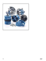
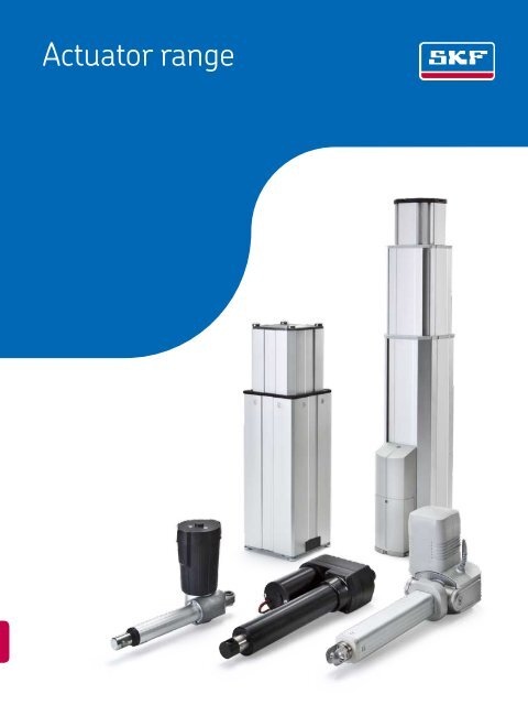
Actuator range
® SKF is a registered trademark of the SKF G<strong>ro</strong>up.<br />
© SKF G<strong>ro</strong>up 2<st<strong>ro</strong>ng>01</st<strong>ro</strong>ng>1<br />
The contents of this publication are the copyright of the publisher and may not be rep<strong>ro</strong>duced (even extracts) unless prior written permission<br />
is granted. Every care has been taken to ensure the accuracy of the information contained in this publication but no liability can be<br />
accepted for any loss or damage whether direct, indirect or consequential arising out of the use of the information contained herein.<br />
PUB MT/P1 10060 EN · January 2<st<strong>ro</strong>ng>01</st<strong>ro</strong>ng>1<br />
This publication supersedes publication 5322.<br />
Printed in Sweden on envi<strong>ro</strong>nmentally friendly paper.
Principles of actuator and pillar selection and application .......... 9<br />
1<br />
Telescopic pillars ......................................... 37<br />
2<br />
Linear actuators ......................................... 107<br />
3<br />
Rotary actuators ......................................... 289<br />
4<br />
Cont<strong>ro</strong>l units ............................................ 3<st<strong>ro</strong>ng>01</st<strong>ro</strong>ng><br />
5<br />
Hand, foot and desk switches ............................... 331<br />
6<br />
Customized p<strong>ro</strong>jects ...................................... 355<br />
7<br />
Drive by wire . . . . . . . . . . . . . . . . . . . . . . . . . . . . . . . . . . . . . . . . . . . 365<br />
8<br />
Spare parts . . . . . . . . . . . . . . . . . . . . . . . . . . . . . . . . . . . . . . . . . . . . 371<br />
9<br />
1
Contents<br />
Foreword .......................................... 4<br />
SKF – the knowledge engineering company . ............. 6<br />
1 Principles of actuator and pillar selection and application.... 9<br />
Linear actuator definition & type . . . . . . . . . . . . . . . . . . . . . . . . 10<br />
Definition . . . . . . . . . . . . . . . . . . . . . . . . . . . . . . . . . . . . . . . . 10<br />
Ball screw vs acme screw ............................ 11<br />
Performance considerations ............................ 11<br />
Limit switch . . . . . . . . . . . . . . . . . . . . . . . . . . . . . . . . . . . . . . 11<br />
Hall sensors . . . . . . . . . . . . . . . . . . . . . . . . . . . . . . . . . . . . . . 11<br />
Potentiometer . . . . . . . . . . . . . . . . . . . . . . . . . . . . . . . . . . . . 11<br />
Friction clutch ..................................... 11<br />
Ball detent clutch . . . . . . . . . . . . . . . . . . . . . . . . . . . . . . . . . . 11<br />
Back-up nut ...................................... 11<br />
Slip-stick effect .................................... 11<br />
Selection criteria . . . . . . . . . . . . . . . . . . . . . . . . . . . . . . . . . . . . 12<br />
Force . . . . . . . . . . . . . . . . . . . . . . . . . . . . . . . . . . . . . . . . . . . 12<br />
Load capacity . . . . . . . . . . . . . . . . . . . . . . . . . . . . . . . . . . . . . 12<br />
Speed ........................................... 12<br />
St<strong>ro</strong>ke and retracted length . . . . . . . . . . . . . . . . . . . . . . . . . . 12<br />
Calculations . . . . . . . . . . . . . . . . . . . . . . . . . . . . . . . . . . . . . . . . 13<br />
Duty cycle and duty factor. . . . . . . . . . . . . . . . . . . . . . . . . . . . 13<br />
Lifetime calculation. . . . . . . . . . . . . . . . . . . . . . . . . . . . . . . . . 13<br />
Application checklist .................................. 14<br />
Typical applications ................................... 15<br />
Selection guide ...................................... 16<br />
2 Telescopic pillars . . . . . . . . . . . . . . . . . . . . . . . . . . . . . . . . . . 37<br />
AC versions<br />
TLC ............................................. 38<br />
TFG . . . . . . . . . . . . . . . . . . . . . . . . . . . . . . . . . . . . . . . . . . . . 42<br />
THC . . . . . . . . . . . . . . . . . . . . . . . . . . . . . . . . . . . . . . . . . . . . 46<br />
TXG . . . . . . . . . . . . . . . . . . . . . . . . . . . . . . . . . . . . . . . . . . . . 50<br />
TGC . . . . . . . . . . . . . . . . . . . . . . . . . . . . . . . . . . . . . . . . . . . . 54<br />
DC versions<br />
CPI ............................................. 60<br />
TLG . . . . . . . . . . . . . . . . . . . . . . . . . . . . . . . . . . . . . . . . . . . . 64<br />
TLT ............................................. 68<br />
TFG . . . . . . . . . . . . . . . . . . . . . . . . . . . . . . . . . . . . . . . . . . . . 72<br />
THG . . . . . . . . . . . . . . . . . . . . . . . . . . . . . . . . . . . . . . . . . . . . 76<br />
CAWA ........................................... 80<br />
TXG . . . . . . . . . . . . . . . . . . . . . . . . . . . . . . . . . . . . . . . . . . . . 84<br />
TMA ............................................ 88<br />
TMD ............................................ 92<br />
No motor<br />
FRE . . . . . . . . . . . . . . . . . . . . . . . . . . . . . . . . . . . . . . . . . . . . 98<br />
TMS ............................................ 1<st<strong>ro</strong>ng>02</st<strong>ro</strong>ng><br />
3 Linear actuators . . . . . . . . . . . . . . . . . . . . . . . . . . . . . . . . . . 107<br />
AC versions<br />
SLS . . . . . . . . . . . . . . . . . . . . . . . . . . . . . . . . . . . . . . . . . . . . 110<br />
SKS/SKA ......................................... 114<br />
SKD . . . . . . . . . . . . . . . . . . . . . . . . . . . . . . . . . . . . . . . . . . . . 118<br />
STD . . . . . . . . . . . . . . . . . . . . . . . . . . . . . . . . . . . . . . . . . . . . 122<br />
STW ............................................ 126<br />
MATRIX 6 ........................................ 130<br />
CAR 40 .......................................... 134<br />
CAHB–31 ........................................ 138<br />
SJ .............................................. 142<br />
DSP . . . . . . . . . . . . . . . . . . . . . . . . . . . . . . . . . . . . . . . . . . . . 146<br />
CAP 32 .......................................... 150<br />
CAR 32 .......................................... 154<br />
<st<strong>ro</strong>ng>CAT</st<strong>ro</strong>ng> 32B ......................................... 158<br />
<st<strong>ro</strong>ng>CAT</st<strong>ro</strong>ng> 33 .......................................... 162<br />
WSP ............................................ 166<br />
CAHB–30 ........................................ 170<br />
<st<strong>ro</strong>ng>CAT</st<strong>ro</strong>ng> 33H ......................................... 174<br />
DC versions<br />
SKG . . . . . . . . . . . . . . . . . . . . . . . . . . . . . . . . . . . . . . . . . . . . 180<br />
STG . . . . . . . . . . . . . . . . . . . . . . . . . . . . . . . . . . . . . . . . . . . . 184<br />
RU . . . . . . . . . . . . . . . . . . . . . . . . . . . . . . . . . . . . . . . . . . . . . 188<br />
MATRIX 3 ........................................ 192<br />
CAR 40 .......................................... 196<br />
ECOMAG ......................................... 200<br />
FD . . . . . . . . . . . . . . . . . . . . . . . . . . . . . . . . . . . . . . . . . . . . . 204<br />
Magdrive . . . . . . . . . . . . . . . . . . . . . . . . . . . . . . . . . . . . . . . . 208<br />
CAHB–21 ........................................ 212<br />
ASM ............................................ 216<br />
CAP 43B. . . . . . . . . . . . . . . . . . . . . . . . . . . . . . . . . . . . . . . . . 220<br />
<st<strong>ro</strong>ng>CAT</st<strong>ro</strong>ng> 32B ......................................... 224<br />
MATRIX 1 ........................................ 228<br />
CAR 32 .......................................... 232<br />
CAP 32 .......................................... 236<br />
CAP 43A ......................................... 240<br />
<st<strong>ro</strong>ng>CAT</st<strong>ro</strong>ng> 33 .......................................... 244<br />
CAHB–20 ........................................ 248<br />
CARE 33 ......................................... 252<br />
CAR 22 .......................................... 256<br />
<st<strong>ro</strong>ng>CAT</st<strong>ro</strong>ng> 33H ......................................... 260<br />
CAHB–10 ........................................ 264<br />
CALA 36A ........................................ 268<br />
<st<strong>ro</strong>ng>CAT</st<strong>ro</strong>ng> 21B ......................................... 272<br />
No motor<br />
CARN 32 . . . . . . . . . . . . . . . . . . . . . . . . . . . . . . . . . . . . . . . . 280<br />
CCBR 32 ......................................... 284<br />
2
4 Rotary actuators . . . . . . . . . . . . . . . . . . . . . . . . . . . . . . . . . . 289<br />
CRAB 17 ......................................... 290<br />
CRAB 05 ......................................... 296<br />
5 Cont<strong>ro</strong>l units . . . . . . . . . . . . . . . . . . . . . . . . . . . . . . . . . . . . . 3<st<strong>ro</strong>ng>01</st<strong>ro</strong>ng><br />
SCU . . . . . . . . . . . . . . . . . . . . . . . . . . . . . . . . . . . . . . . . . . . . 3<st<strong>ro</strong>ng>02</st<strong>ro</strong>ng><br />
VCU . . . . . . . . . . . . . . . . . . . . . . . . . . . . . . . . . . . . . . . . . . . . 306<br />
BCU . . . . . . . . . . . . . . . . . . . . . . . . . . . . . . . . . . . . . . . . . . . . 310<br />
CB . . . . . . . . . . . . . . . . . . . . . . . . . . . . . . . . . . . . . . . . . . . . . 314<br />
MCU ............................................ 316<br />
LD . . . . . . . . . . . . . . . . . . . . . . . . . . . . . . . . . . . . . . . . . . . . . 318<br />
CAED ANR . . . . . . . . . . . . . . . . . . . . . . . . . . . . . . . . . . . . . . . 322<br />
CAED . . . . . . . . . . . . . . . . . . . . . . . . . . . . . . . . . . . . . . . . . . . 324<br />
CAEV . . . . . . . . . . . . . . . . . . . . . . . . . . . . . . . . . . . . . . . . . . . 326<br />
6 Accessories . . . . . . . . . . . . . . . . . . . . . . . . . . . . . . . . . . . . . . 331<br />
Hand switches<br />
EHA 1 ........................................... 332<br />
EHA 3 ........................................... 334<br />
EHE . . . . . . . . . . . . . . . . . . . . . . . . . . . . . . . . . . . . . . . . . . . . 336<br />
HS . . . . . . . . . . . . . . . . . . . . . . . . . . . . . . . . . . . . . . . . . . . . . 338<br />
PHC . . . . . . . . . . . . . . . . . . . . . . . . . . . . . . . . . . . . . . . . . . . . 340<br />
CAES . . . . . . . . . . . . . . . . . . . . . . . . . . . . . . . . . . . . . . . . . . . 342<br />
Foot switches<br />
ST .............................................. 344<br />
PFP . . . . . . . . . . . . . . . . . . . . . . . . . . . . . . . . . . . . . . . . . . . . 346<br />
Desk switches<br />
ST .............................................. 348<br />
LD . . . . . . . . . . . . . . . . . . . . . . . . . . . . . . . . . . . . . . . . . . . . . 350<br />
PAM ............................................ 352<br />
7 Customized p<strong>ro</strong>jects only ............................ 355<br />
Rotary actuators ................................... 356<br />
CEMC actuator series ............................... 358<br />
SRSA actuator series . . . . . . . . . . . . . . . . . . . . . . . . . . . . . . . 362<br />
8 Drive by wire . . . . . . . . . . . . . . . . . . . . . . . . . . . . . . . . . . . . . 365<br />
EPB . . . . . . . . . . . . . . . . . . . . . . . . . . . . . . . . . . . . . . . . . . . . 366<br />
9 Spare parts . . . . . . . . . . . . . . . . . . . . . . . . . . . . . . . . . . . . . . 371<br />
3
Foreword<br />
The SKF brand now stands for more<br />
than ever before, and means more<br />
to you as a valued customer.<br />
While SKF maintains its leadership<br />
as the hallmark of quality bearings<br />
th<strong>ro</strong>ughout the world, new dimensions<br />
in technical advances, p<strong>ro</strong>duct support<br />
and services have evol ved SKF into<br />
a truly solutions-oriented supplier,<br />
creating greater value for customers.<br />
These solutions encompass ways to<br />
bring greater p<strong>ro</strong>ductivity to customers,<br />
not only with breakth<strong>ro</strong>ugh applicationspecific<br />
p<strong>ro</strong>ducts, but also th<strong>ro</strong>ugh<br />
leading-edge design simulation tools<br />
and consultancy services, plant asset<br />
efficiency maintenance p<strong>ro</strong>gram mes,<br />
and the industry’s most advanced<br />
supply management techniques.<br />
The SKF brand still stands for the very<br />
best in <strong>ro</strong>lling bearings, but it now<br />
stands for much more.<br />
SKF – the knowledge engineering<br />
company<br />
This publication p<strong>ro</strong>vides information on all<br />
the SKF Actuation System p<strong>ro</strong>ducts with<br />
clear tables to help the customer select and<br />
order the right p<strong>ro</strong>duct.<br />
Structure of the catalogue<br />
This catalogue is divided into nine main<br />
chapters, marked with numbered blue tabs<br />
in the right margin:<br />
• Chapter 1 p<strong>ro</strong>vides technical and application<br />
recommendations.<br />
• Chapter 2 describes the different telescopic<br />
pillars.<br />
• Chapter 3 presents the linear actuator<br />
series.<br />
• Chapter 4 displays data about <strong>ro</strong>tary<br />
actuators.<br />
• Chapter 5 and 6 contain information<br />
about cont<strong>ro</strong>l units and accessories.<br />
• Chapter 7 gives a brief description of<br />
p<strong>ro</strong>ducts dedicated to p<strong>ro</strong>ject sales.<br />
• Chapter 8 int<strong>ro</strong>duces the Elect<strong>ro</strong>nic Parking<br />
Brake by Drive by Wire.<br />
• Chapter 9 lists the different spare parts<br />
and accessories.<br />
About the data in this<br />
catalogue<br />
The data in this catalogue relate to SKF’s<br />
state-of-the-art technology and p<strong>ro</strong>duction<br />
capabilities as of 2<st<strong>ro</strong>ng>01</st<strong>ro</strong>ng>0. The data may differ<br />
f<strong>ro</strong>m that presented in earlier catalogues<br />
because of redesign, technological developments,<br />
or revised methods of calculation.<br />
SKF reserves the right to make continuing<br />
imp<strong>ro</strong>vements to SKF p<strong>ro</strong>ducts regarding<br />
materials, design and manufacturing methods,<br />
as well as changes necessitated by<br />
technological developments.<br />
How to use this catalogue<br />
Each p<strong>ro</strong>duct is int<strong>ro</strong>duced by p<strong>ro</strong>viding information<br />
such as technical data, dimensional<br />
drawings or connecting diagrams, in<br />
order to make it easy to select the right<br />
p<strong>ro</strong>duct.<br />
4
At the end of each p<strong>ro</strong>duct information<br />
section, an ordering key is shown.<br />
To determine the p<strong>ro</strong>duct code to be used<br />
on the order, examine the relevant pages<br />
containing the main data and prepare the<br />
order code. This may consist of pre-set options,<br />
ordering key boxes already filled in (for<br />
example: type, color, etc.) and options that<br />
can be selected f<strong>ro</strong>m several empty boxes<br />
(for example: voltage and st<strong>ro</strong>ke length). In<br />
the ordering key, the options are set out under<br />
the associated subjects, with the code or<br />
the information to be entered indicated<br />
along with the measurement restrictions<br />
contained in the associated tables. The sequence<br />
of the ordering key is defined by the<br />
thin guiding lines that select the corresponding<br />
box. The individual ordering key<br />
may contain indications or special notes.<br />
For the <st<strong>ro</strong>ng>CAT</st<strong>ro</strong>ng> series, the selection of the<br />
item’s dynamic load/speed and motor option<br />
should be made by use of an additional table<br />
with several options located above the ordering<br />
key.<br />
An example is given below to show how to<br />
prepare the order code for a MAX 6 linear<br />
actuator.<br />
NOTE: See p<strong>ro</strong>duct specific catalogues at<br />
www.actuators.skf.com for more complete<br />
information and descriptions of the various<br />
p<strong>ro</strong>ducts briefly described in this catalogue.<br />
Features for selection<br />
(highlighted in bold type)<br />
Pre-selected<br />
type of actuator<br />
Selection of<br />
voltage<br />
Pre-selected<br />
option<br />
Selection of the st<strong>ro</strong>ke<br />
and retracted length<br />
Selection of<br />
orientation<br />
M A X 6 – A A 0 0 – 0 0 0<br />
Type<br />
Motor voltage:<br />
230 V AC/50 Hz, integrated low voltage 4<br />
120 V AC/60 Hz, integrated low voltage 5<br />
St<strong>ro</strong>ke (S):<br />
100 mm 100 315<br />
150 mm 150 365<br />
200 mm 200 415<br />
300 mm 300 515<br />
700 mm 700 980<br />
Pre-selected<br />
options<br />
Orientation of rear attachment:<br />
Standard 1<br />
Turned 90° 2<br />
Options, alphanumeric identity code of the required item, are<br />
to be written in the corresponding box of the ordering key<br />
Example<br />
M A X 6 4 – A 1 0 0 3 1 5 A 0 1 0 – 0 0 0<br />
Example of an ordering key that has been filled in<br />
5
SKF – the knowledge engineering<br />
company<br />
F<strong>ro</strong>m the company that invented the selfaligning<br />
ball bearing more than 100 years<br />
ago, SKF has evol ved into a knowledge<br />
engin eering company that is able to draw on<br />
five technology platforms to create unique<br />
solutions for its custom ers. These platforms<br />
include bearings, bearing units and seals, of<br />
course, but extend to other areas including:<br />
lubricants and lubrication sys tems, critical<br />
for long bearing life in many appli cations;<br />
mecha t<strong>ro</strong>nics that combine mech anical and<br />
elect<strong>ro</strong>n ics knowledge into systems for more<br />
effective linear motion and sensorized solutions;<br />
and a full range of ser vices, f<strong>ro</strong>m design<br />
and logistics support to con dition monitoring<br />
and reliability systems.<br />
Though the scope has b<strong>ro</strong>adened, SKF<br />
continues to maintain the world’s leadership<br />
in the design, manufacture and marketing of<br />
<strong>ro</strong>lling bearings, as well as complementary<br />
p<strong>ro</strong>ducts such as radial seals. SKF also holds<br />
an increasingly important position in the<br />
market for linear motion p<strong>ro</strong>ducts, highprecision<br />
ae<strong>ro</strong>space bearings, machine tool<br />
spindles and plant maintenance services.<br />
The SKF G<strong>ro</strong>up is globally certified to ISO<br />
140<st<strong>ro</strong>ng>01</st<strong>ro</strong>ng>, the international standard for envi r-<br />
o n mental management, as well as OHSAS<br />
180<st<strong>ro</strong>ng>01</st<strong>ro</strong>ng>, the health and safety manage ment<br />
standard. Individual divisions have been<br />
ap p<strong>ro</strong>ved for quality certification in ac cordance<br />
with ISO 90<st<strong>ro</strong>ng>01</st<strong>ro</strong>ng> and other customer<br />
specific requirements.<br />
With over 100 manufacturing sites worldwide<br />
and sales companies in 70 countries,<br />
SKF is a truly international corporation. In<br />
addition, our distributors and dealers in<br />
some 15 000 locations a<strong>ro</strong>und the world,<br />
an e-business marketplace and a global<br />
distri bution system put SKF close to customers<br />
for the supply of both p<strong>ro</strong>ducts and<br />
services. In essence, SKF solutions are available<br />
wherever and whenever customers<br />
need them. Over all, the SKF brand and the<br />
corporation are st<strong>ro</strong>nger than ever. As the<br />
knowledge engin eering company, we stand<br />
ready to serve you with world-class p<strong>ro</strong>duct<br />
competencies, intellectual resources, and<br />
the vision to help you succeed.<br />
© Airbus – photo: e x m company, H. Goussé<br />
Evolving by-wire technology<br />
SKF has a unique expertise in the fast-g<strong>ro</strong>wing bywire<br />
technology, f<strong>ro</strong>m fly-by-wire, to drive-bywire,<br />
to work-by-wire. SKF pioneered practical flyby-wire<br />
technology and is a close working partner<br />
with all ae<strong>ro</strong>space industry leaders. As an example,<br />
virtually all aircraft of the Airbus design use SKF<br />
by-wire systems for cockpit flight cont<strong>ro</strong>l.<br />
SKF is also a leader in automotive by-wire technology,<br />
and has partnered with automotive engineers<br />
to develop two concept cars, which employ<br />
SKF mechat<strong>ro</strong>nics for steering and braking. Further<br />
by-wire develop ment has led SKF to p<strong>ro</strong>duce<br />
an all-electric forklift truck, which uses mechat<strong>ro</strong>nics<br />
rather than hydraulics for all cont<strong>ro</strong>ls.<br />
Seals<br />
Bearings<br />
and units<br />
Lubrication<br />
systems<br />
Mechat<strong>ro</strong>nics<br />
Services<br />
6
Harnessing wind power<br />
The g<strong>ro</strong>wing industry of wind-generated electric power p<strong>ro</strong>vides a source of<br />
clean, green electricity. SKF is working closely with global industry leaders to<br />
develop efficient and t<strong>ro</strong>uble-free turbines, p<strong>ro</strong>viding a wide range of large,<br />
highly specialized bearings and condition monitoring systems to extend equipment<br />
life of wind farms located in even the most remote and inhospitable<br />
envi<strong>ro</strong>nments.<br />
Working in extreme envi<strong>ro</strong>nments<br />
In frigid winters, especially in northern countries, extreme sub-ze<strong>ro</strong> temperatures<br />
can cause bearings in railway axleboxes to seize due to lubrication starvation.<br />
SKF created a new family of synthetic lubricants formulated to retain<br />
their lubrication viscosity even at these extreme temperatures. SKF knowledge<br />
enables manufacturers and end user customers to overcome the performance<br />
issues resulting f<strong>ro</strong>m extreme temperatures, whether hot or cold. For example,<br />
SKF p<strong>ro</strong>ducts are at work in diverse envi<strong>ro</strong>nments such as baking ovens and<br />
instant freezing in food p<strong>ro</strong>cessing plants.<br />
Developing a cleaner cleaner<br />
The electric motor and its bearings are the heart of many household appliances.<br />
SKF works closely with appliance manufacturers to imp<strong>ro</strong>ve their p<strong>ro</strong>ducts’<br />
performance, cut costs, reduce weight, and reduce energy consumption.<br />
A recent example of this cooperation is a new generation of vacuum cleaners<br />
with substantially more suction. SKF knowledge in the area of small bearing<br />
technology is also applied to manufacturers of power tools and office<br />
equipment.<br />
Maintaining a 350 km/h R&D lab<br />
In addition to SKF’s renowned research and development facilities in Eu<strong>ro</strong>pe<br />
and the United States, Formula One car racing p<strong>ro</strong>vides a unique envi<strong>ro</strong>nment<br />
for SKF to push the limits of bearing technology. For over 60 years, SKF p<strong>ro</strong>ducts,<br />
engineering and knowledge have helped make Scuderia Ferrari a formidable<br />
force in F1 racing. (The average racing Ferrari utilizes a<strong>ro</strong>und 150 SKF<br />
components.) Lessons learned here are applied to the p<strong>ro</strong>ducts we p<strong>ro</strong>vide to<br />
automakers and the aftermarket worldwide.<br />
Delivering Asset Efficiency Optimization<br />
Th<strong>ro</strong>ugh SKF Reliability Systems, SKF p<strong>ro</strong>vides a comprehensive range of<br />
asset efficiency p<strong>ro</strong>ducts and services, f<strong>ro</strong>m condition monitoring hardware<br />
and software to maintenance strategies, engineering assistance and machine<br />
reliability p<strong>ro</strong>grammes. To optimize efficiency and boost p<strong>ro</strong>ductivity, some<br />
industrial facil ities opt for an Integrated Maintenance Solution, in which SKF<br />
delivers all ser vices under one fixed-fee, performance-based contract.<br />
Planning for sustainable g<strong>ro</strong>wth<br />
By their very nature, bearings make a positive contribution to the natural<br />
envi<strong>ro</strong>nment, enabling machinery to operate more efficiently, consume less<br />
power, and require less lubrication. By raising the performance bar for our<br />
own p<strong>ro</strong>ducts, SKF is enabling a new generation of high-efficiency p<strong>ro</strong>ducts<br />
and equipment. With an eye to the future and the world we will leave to our<br />
children, the SKF G<strong>ro</strong>up policy on envi<strong>ro</strong>nment, health and safety, as well as<br />
the manufacturing techniques, are planned and implemented to help p<strong>ro</strong>tect<br />
and preserve the earth’s limited natural resources. We remain committed to<br />
sustainable, envi<strong>ro</strong>nmentally responsible g<strong>ro</strong>wth.<br />
7
Principles of actuator and pillar<br />
selection and application<br />
1<br />
Linear actuator definition and type ....................................... 10<br />
Performance considerations ............................................ 11<br />
Selection criteria . . . . . . . . . . . . . . . . . . . . . . . . . . . . . . . . . . . . . . . . . . . . . . . . . . . . 12<br />
Calculations . . . . . . . . . . . . . . . . . . . . . . . . . . . . . . . . . . . . . . . . . . . . . . . . . . . . . . . . 13<br />
Application checklist .................................................. 14<br />
Typical applications ................................................... 15<br />
Selection guide ...................................................... 16<br />
9
Linear actuator<br />
definition and type<br />
Definition: Elect<strong>ro</strong>-mechanical linear actuators<br />
enable precise, cont<strong>ro</strong>lled, and repeatable<br />
push/pull movement in linear drive<br />
applications (see illustrations below).<br />
Linear actuators serve as efficient, virtually<br />
maintenance-free, and envi<strong>ro</strong>nmentally<br />
friendly alternatives to hydraulic or pneumatic<br />
types.<br />
Standard versions can handle loads as<br />
great as 12 kN, deliver speeds up to<br />
150 mm/s, and travel as far as 1 500 mm.<br />
They can be self-contained in aluminum,<br />
zinc, or polymer housings and ready-tomount<br />
for easy plug-in operation.<br />
Actuators with modular design and open<br />
architecture offer opportunities to choose<br />
and integrate components to achieve customized<br />
solutions within existing envelopes.<br />
Application potential expands with the int<strong>ro</strong>duction<br />
of technologies for specific purpo–<br />
ses, such as hall sensors, limit switches, potentiometers,<br />
friction clutches, or back-up<br />
nuts.<br />
Screw-type linear actuators powered by<br />
an electric AC or DC motor basically consist<br />
of a lead screw (threaded shaft/spindle) with<br />
drive nut and push tube. In 90 % of the cases,<br />
a gearbox between the motor and the<br />
screw is also present.<br />
When power is supplied, the motor <strong>ro</strong>tates<br />
the lead screw, which causes the drive<br />
nut to travel and extend the push tube. Reversing<br />
the motor <strong>ro</strong>tation retracts the push<br />
tube.<br />
Pushing/pulling<br />
1 2 7<br />
5<br />
Opening/closing<br />
3<br />
6<br />
4<br />
Legend:<br />
1. Motor<br />
2. Gearbox<br />
3. Screw and nut<br />
4. P<strong>ro</strong>tection tube<br />
5. Push tube<br />
6. F<strong>ro</strong>nt attachment<br />
7. Rear attachment<br />
Clamping/gripping<br />
Raising/lowering<br />
Tilting<br />
10
Ball screw<br />
Acme screw<br />
Friction clutch<br />
1<br />
Ball screw vs. acme screw: Traditional<br />
types of lead screws include ball screws and<br />
acme screws, whose specification will be influenced<br />
by an actuator’s configuration and<br />
load requirements.<br />
Ball screws: All-steel ball screws consist of<br />
a screw shaft, ball nut with a ball recirculation<br />
system to convert <strong>ro</strong>tary motion into<br />
smooth, accurate, and reversible linear motion<br />
(or torque to thrust). The <strong>ro</strong>w of circular<br />
<strong>ro</strong>lling elements is self-contained in a closed<br />
system between the nut and screw for a design<br />
exhibiting extremely low friction coefficients.<br />
The low frictional resistance minimizes<br />
wear, imp<strong>ro</strong>ves efficiency, and reduces<br />
operating temperature for longer service<br />
life.<br />
Ball screws can handle extreme loads,<br />
achieve high duty cycles, operate over a<br />
wide temperature range, and deliver the<br />
precision necessary to equip actuators performing<br />
over long periods at high speeds<br />
and requiring high dynamic capability.<br />
Brakes usually will be specified for ball<br />
screw actuators to prevent back-drive.<br />
Acme screws: These screws transmit torque<br />
into linear motion th<strong>ro</strong>ugh direct sliding friction.<br />
A typical assembly consists of a steel<br />
screw and plastic nut.<br />
Some of the p<strong>ro</strong>ducts are equipped with<br />
acme screws with a relatively high friction<br />
coefficient that makes them well suited for<br />
self-locking application. Acme screw actuators<br />
accommodate high static load, withstand<br />
excessive vibration, operate quietly,<br />
and represent cost-effective solutions.<br />
Performance<br />
considerations<br />
Beyond the basic fundamentals of actuator<br />
operation, applications may require feedback<br />
on position and/or direction, limits on<br />
motion or travel in a particular direction, or<br />
p<strong>ro</strong>tection against dynamic overload. Enabling<br />
technologies have been developed for<br />
these purposes.<br />
Limit switch: Its purpose is to limit actuator<br />
motion or travel in a particular direction.<br />
When activated, the switch opens or closes<br />
an electrical contact. When the contact is<br />
closed, current will flow th<strong>ro</strong>ugh the switch;<br />
when the contact is open, no current will<br />
flow th<strong>ro</strong>ugh the switch. These devices prevent<br />
actuators f<strong>ro</strong>m running into the mechanical<br />
ends and may allow for the adjustment<br />
of st<strong>ro</strong>ke length.<br />
Hall sensors: These <strong>ro</strong>tary or linear sensing<br />
devices determine the relative position of an<br />
actuator. Two sensors detect the changing<br />
magnetic field created by a <strong>ro</strong>tating magnet<br />
and then relay corresponding output pulses<br />
to a cont<strong>ro</strong>l unit to p<strong>ro</strong>vide the position<br />
feedback.<br />
Potentiometer: A potentiometer is an<br />
analouge feedback device. The potentiometer<br />
is considered as an absolute sensor<br />
with unique value in each position. Sometimes<br />
it is called a variable resistance that<br />
can be read and feed into a cont<strong>ro</strong>ller for<br />
positioning cont<strong>ro</strong>l of the application.<br />
Friction clutch: This function will p<strong>ro</strong>tect<br />
the actuator f<strong>ro</strong>m mechanical damage when<br />
it reaches either of its mechanical end positions<br />
or when the maximum dynamic load is<br />
momentarily exceeded. A friction clutch consists<br />
of a series of steel plates engaging a<br />
hub and a series of friction rings engaging a<br />
housing. Pressure is exerted on the plates<br />
and rings by an adjuster acting th<strong>ro</strong>ugh a<br />
spring and pressure plate. The friction clutch<br />
is not intended for use as a load limiter, but<br />
only for p<strong>ro</strong>tection of the actuator and enduse<br />
equipment in the event of dynamic<br />
overload.<br />
Ball detent clutch: A ball detent type clutch<br />
transmits force th<strong>ro</strong>ugh hardened balls<br />
which rest in detents on the shaft and are<br />
held in place with springs. An overtorque/<br />
load condition pushes the balls out of their<br />
detents, thereby decoupling the lead-screw<br />
f<strong>ro</strong>m the motor.<br />
Back-up nut: This prevents an actuator<br />
f<strong>ro</strong>m collapsing if a drive nut fails. The backup<br />
nut is usually in metal, exhibits greater<br />
anti-shear strength than the drive nut, and<br />
only makes contact with the threads of the<br />
spindle when the threads of the drive nut<br />
fail. The back-up nut carries the load and<br />
may be able to lower the load (signaling<br />
need for repair).<br />
Slip stick effect: The cycle of alternating<br />
slipping and sticking as two surfaces rub<br />
against each other. The effect is vibration<br />
and noise. Resonances within other materials<br />
can occur. This effect can sometimes be<br />
heard, felt or seen. With linear actuators,<br />
Slip stick has been witnessed between the<br />
Delrin and aluminum or steel, such as between<br />
drive nut and spindle, and glide pad<br />
and extrusion.<br />
11
Selection criteria<br />
An actuator’s performance will be influenced<br />
by a variety of factors intrinsic to an application.<br />
An understanding of these factors can<br />
help you select the most suitable actuator<br />
design and solution. Relevant factors to<br />
evaluate include push/pull force, static and<br />
dynamic load capacity, speed, st<strong>ro</strong>ke and retracted<br />
length, duty cycle, and life<br />
calculation.<br />
Force: Push force is the maximum extending<br />
force that an electric linear actuator can<br />
p<strong>ro</strong>duce in Newtons (N). Pull force is the<br />
maximum retracting force. Some actuators<br />
do not p<strong>ro</strong>duce equal push and pull forces,<br />
while others do not permit pull force.<br />
Load capacity: Maximum static load refers<br />
to the weight or mass that an actuator can<br />
handle when standing still without causing<br />
permanent damage or causing the actuator<br />
to start “going backwards.” (Subjecting an<br />
actuator to loads in excess of stated values<br />
can increase the risk of permanent deformation<br />
to some parts.) Maximum dynamic<br />
load represents the maximum total weight<br />
or mass that the actuator can move. The<br />
decisive factor for this value is the size of the<br />
motor and the type of gearing. Some versions<br />
feature an integral mechanical safety<br />
device similar to a clutch to p<strong>ro</strong>tect the motor<br />
and gears f<strong>ro</strong>m damage.<br />
Speed: This represents the rate of travel<br />
(when extending or retracting) and is usually<br />
measured in mm/s or in./s. Speed can vary<br />
under different loads, often depending on<br />
the motor. Actuators with DC motors exhibit<br />
a speed variation inversely p<strong>ro</strong>portional to<br />
the load. Actuators with AC motors move at<br />
more consistent speed, which is only slightly<br />
affected by the load. Other factors impacting<br />
the speed will include the magnitude and/or<br />
frequency of the applied voltage, the ambient<br />
temperature, and how well an actuator<br />
is integrated into the end-use application.<br />
St<strong>ro</strong>ke and retracted length: The st<strong>ro</strong>ke<br />
describes the length (in millimeters or inches)<br />
that an elect<strong>ro</strong>-mechanical linear actuator<br />
or telescopic pillar will extend or retract.<br />
The retracted length is the shortest distance<br />
between the two fixed points on an actuator<br />
when the actuator is in its innermost position.<br />
The dimensions reflect a measurement<br />
f<strong>ro</strong>m the center of the rear and f<strong>ro</strong>nt<br />
mounting holes.<br />
Retracted length<br />
St<strong>ro</strong>ke length<br />
Retracted length<br />
St<strong>ro</strong>ke length<br />
12
Calculations<br />
Duty cycle and duty factor: This defines the<br />
maximum period during actuator operation<br />
without interruption. The co<strong>ro</strong>llary duty factor<br />
expresses how long an actuator can<br />
handle non-stop operation before it overheats<br />
or is otherwise damaged. Many variables<br />
will affect the duty cycle, including<br />
running time, application, design, installation,<br />
and components. It is necessary for you<br />
to assess the type of task, its duration, frequency,<br />
and repetitiveness when evaluating<br />
expected duty cycle.<br />
SKF linear actuators are designed for intermittent<br />
operation. Permitted load is related<br />
to the duty factor i.e. load must be reduced,<br />
when the duty factor is increased.<br />
Duty cycle is defined as the relation between<br />
operational time, load and rest time. In the<br />
diagrams, maximum load is shown as a<br />
function of duty cycle. If the recommended<br />
duty factor is exceeded, the actuator may<br />
overheat and be damaged.<br />
Permitted load for DC-actuators at a specific<br />
duty factor is expressed in percentage<br />
of maximum dynamic load capacity<br />
(† fig. 1).<br />
N<br />
Duty factor % = —— 100<br />
N+R<br />
where<br />
N = running period<br />
under load<br />
R = rest pe ri od<br />
N+R = to tal cy cle time<br />
Example:<br />
An actuator is running with the following cycle,<br />
5 seconds running, 5 seconds rest,<br />
5 seconds running, 15 seconds rest, and so<br />
on.<br />
Calculate duty factor and maximum load<br />
for this working cycle.<br />
5+5<br />
Duty factor = –—––––––––– 100 = 33%<br />
(5+5) + (5+15)<br />
Max. dynamic load = 5 000 N<br />
Permitted load = 0,73 ¥ 5 000 = 3 650 N<br />
Life calculation: An actuator’s life expectancy<br />
is divided into two types: its life and its<br />
service (or operational) life. The actuator’s<br />
life is defined as the time the actuator can<br />
live without being derated due to age. The<br />
actuator’s service life is defined as the time<br />
(or how many cycles) the actuator can operate.<br />
For example, an actuator is installed to<br />
operate once a day for 10 years. Its expected<br />
life is 10 years and its required service life is<br />
10 ¥ 365 cycles.<br />
The service life of a ball screw actuator<br />
normally will be determined by the L 10 life of<br />
the ball screw. In most cases, there is less<br />
wear on the worm gear and bearings than<br />
on the ball screw.<br />
Under certain circumstances, the life of<br />
the motor is shorter than that of the ball<br />
screw. Generally, the life of DC-motors is reduced<br />
when load and number of starts/<br />
stops are increased.<br />
To calculate the basic rating life L 10 of a ball<br />
screw, all you need to know is the dynamic<br />
load and actual st<strong>ro</strong>ke. L 10 is defined as the<br />
life that 90% of a sufficiently large g<strong>ro</strong>up of<br />
apparently identical ball screws can be expected<br />
to attain or exceed.<br />
500 000 p q C w 3<br />
L 10d s = ————— —<br />
S < F M<br />
z<br />
where<br />
L 10 d s = ba sic rat ing life in dou ble st<strong>ro</strong>kes<br />
i.e. a st<strong>ro</strong>ke f<strong>ro</strong>m one end po si tion<br />
to the oth er and back again.<br />
p = lead of the ball screw (mm).<br />
S = ac tu al st<strong>ro</strong>ke (mm).<br />
C = ball screw ba sic dy nam ic load<br />
rating (N).<br />
= cubic mean load (N).<br />
F M<br />
In many cases, the magnitude of the load<br />
fluctuates. In order to calculate the equivalent<br />
screw load, it is first necessary to determine<br />
a constant mean load F m which would<br />
have the same influence on the ball screw as<br />
the actually fluctuating load. A constant<br />
mean load can be obtained f<strong>ro</strong>m the formula<br />
below.<br />
3<br />
F 1<br />
3 S 1 +F 2<br />
3 S 2 +F 3<br />
3 S 3 +...<br />
F M = ——————————<br />
S 1 +S 2 +S 3 +...<br />
Example:<br />
An actuator with a st<strong>ro</strong>ke of 500 mm has a<br />
load of 2 800 N in one direction of movement<br />
and 2 100 N in the other. The entire<br />
st<strong>ro</strong>ke of the actuator is utilized.<br />
1<br />
Fig. 1<br />
Duty factor (%) at 20°C<br />
100<br />
80<br />
60<br />
3<br />
2 800 3 ¥500+2 100 3 ¥500<br />
F M = ––————————— = 2 500<br />
500+500<br />
N<br />
R<br />
40<br />
20<br />
N+R<br />
t<br />
0<br />
0 20 40 60 80 100<br />
Load (N)<br />
13
Application checklist<br />
Designing and specifying an elect<strong>ro</strong>-mechanical linear actuator<br />
begins by assessing as many application factors as possible to<br />
make the most app<strong>ro</strong>priate and educated technology choices.<br />
• How much force and in what directions (push, pull, vertical,<br />
and/or horizontal) will the actuator need to move<br />
• How far and how fast will the actuator need to travel<br />
• How often will the actuator operate and how much time will<br />
elapse between operations<br />
• What is the desired lifetime for the application<br />
• How will the actuator be mounted and will f<strong>ro</strong>nt and/or back<br />
mounts require special configurations<br />
• Does the application suggest a need for safety mechanisms<br />
• Will envi<strong>ro</strong>nmental factors (temperature variations, moisture,<br />
or vibration) pose a challenge to operation<br />
• Is space limited<br />
• What are the power supply options<br />
• If a motor is used, what type (AC, DC, or special)<br />
and what voltage<br />
• Is feedback required for speed and/or position<br />
• Are revised specifications likely or anticipated in the future<br />
14
Typical applications<br />
1<br />
Off-highway<br />
Hood lifter<br />
Highway mobile sign<br />
Food and<br />
beverage<br />
Grill<br />
Tilting pan<br />
Medical<br />
Imaging system<br />
Incubator<br />
Healthcare<br />
Treadmill<br />
Massage table<br />
Solar tracking<br />
Solar tracker<br />
Factory<br />
automation<br />
Adjustable workstation<br />
Frame gripper<br />
15
Selection guide<br />
Telescopic pillars<br />
AC versions<br />
Type Voltage Max rated load Max speed St<strong>ro</strong>ke (S) Page<br />
push pull full load no load<br />
– V N N mm/s mm/s mm No.<br />
TLC 120 or 230 AC 4 000 4 000 15 22 100 to 700 38<br />
TFG 50 120 AC 2 500 2 500 15 19 200 to 700 42<br />
TFG 90 230 AC 2 500 2 500 15 19 200 to 700 42<br />
THC 120 or 230 AC 1 800 1 800 15 20 200 to 700 46<br />
TXG 120 or 230 AC 1 500 0 17 23 200 to 600 50<br />
TGC 120 or 230 AC 1 000 1 000 11 12 200 to 700 54<br />
16
Selection guide<br />
Telescopic pillars<br />
DC versions<br />
Type Voltage Max rated load Max speed St<strong>ro</strong>ke (S) Page<br />
push pull full load no load<br />
– V N N mm/s mm/s mm No.<br />
1<br />
CPI 24 DC 4 000 4 000 31 38 200 to 700 60<br />
TLG 24 DC 4 000 0 25 33 200 to 700 64<br />
TLT 24 DC 4 000 0 25 42 300 to 700 68<br />
TFG 10 24 DC 2 500 2500 15 19 200 to 700 72<br />
THG 24 DC 2 000 0 12 15 200 to 700 76<br />
CAWA 24 DC 1 650 0 14 22 500 to 1 000 80<br />
17
Selection guide<br />
Telescopic pillars<br />
DC versions<br />
Type Voltage Max rated load Max speed St<strong>ro</strong>ke (S) Page<br />
push pull full load no load<br />
– V N N mm/s mm/s mm No.<br />
TXG 24 DC 1 500 0 17 23 200 to 600 84<br />
TMA 24 DC 1 000 0 35 55 500 88<br />
TMD 24 DC 800 0 35 60 700 92<br />
Telescopic pillars<br />
No motor<br />
Type Voltage Max load Max speed St<strong>ro</strong>ke (S) Page<br />
push pull full load no load<br />
– V N N mm/s mm/s mm No.<br />
FRE No motor N/A N/A N/A N/A 200 to 700 98<br />
TMS No motor 4 000 4 000 N/A N/A 250 to 700 1<st<strong>ro</strong>ng>02</st<strong>ro</strong>ng><br />
18
Selection guide<br />
Telescopic pillars - retracted length/bending load ratio<br />
1<br />
Retracted length (mm)<br />
THG BA<br />
(s+270)<br />
253 Nm<br />
TMA<br />
(s+140)<br />
190 Nm<br />
TXG<br />
(s+180/160)<br />
200 Nm<br />
CPI 3 sect.<br />
(s+145)<br />
270 Nm<br />
THG BD4<br />
(s+180)<br />
550 Nm<br />
TFG<br />
(s+130)<br />
500 Nm<br />
TLG10-XA.<br />
(s+180)<br />
600 Nm<br />
TLC ZWA<br />
(s+75)<br />
600 Nm<br />
TLG10-XD<br />
(s+180)<br />
1 200 Nm<br />
TLC ZWD<br />
(s+60)<br />
1 000 Nm<br />
TMD<br />
(0,5s+200)<br />
110 Nm<br />
TLT 1<br />
(0,5s+170)<br />
375 Nm<br />
TLT 2<br />
(0,5s+240)<br />
900 Nm<br />
TMS<br />
(0,5s+176)<br />
3 000 Nm<br />
500 1 000<br />
Bending load (Nm)<br />
3-section<br />
tube set<br />
2-section<br />
tube set<br />
19
Selection guide<br />
Linear actuators<br />
AC versions<br />
Type Voltage Max rated load Max speed St<strong>ro</strong>ke (S) Page<br />
push pull full load no load<br />
– V N N mm/s mm/s mm No.<br />
SLS 3400 AC 50 000 50 000 74 88 100 to 700 110<br />
SKS/SKA 3400 AC 30 000 30 000 45 54 100 to 700 114<br />
SKD 3400 AC 15 000 15 000 25 33 100 to 700 118<br />
STD 3400 AC 15 000 15 000 10 14 100 to 700 122<br />
STW 230 AC 15 000 15 000 12 13 100 to 700 126<br />
MAX 6 120 or 230 AC 8 000 6 000 13 18 50 to 700 130<br />
20
Selection guide<br />
Linear actuators<br />
AC versions<br />
Type Voltage Max rated load Max speed St<strong>ro</strong>ke (S) Page<br />
push pull full load no load<br />
– V N N mm/s mm/s mm No.<br />
1<br />
CAR 40 120 or 230 AC 6 000 6 000 40 40 100 to 700 134<br />
CAHB–31 115 or 230 AC 6 000 6 000 48 57 1<st<strong>ro</strong>ng>02</st<strong>ro</strong>ng> to 610 138<br />
SJ 115 or 230 AC 5 000 5 000 6,6 7,2 100 to 600 142<br />
DSP 3400 AC 4 500 4 500 50 58 100 to 700 146<br />
CAP 32 120 or 230 AC 3 500 3 500 32 32 50 to 700 150<br />
CAR 32 120 or 230 AC 3 500 3 500 32 32 50 to 700 154<br />
21
Selection guide<br />
Linear actuators<br />
AC versions<br />
Type Voltage Max rated load Max speed St<strong>ro</strong>ke (S) Page<br />
push pull full load no load<br />
– V N N mm/s mm/s mm No.<br />
<st<strong>ro</strong>ng>CAT</st<strong>ro</strong>ng> 32B 120, 230 or 400 AC 3 500 3 500 32 32 50 to 700 158<br />
<st<strong>ro</strong>ng>CAT</st<strong>ro</strong>ng> 33 120, 230 or 400 AC 3 000 3 000 24 24 100 to 400 162<br />
WSP 230 AC 2 600 2 600 50 50 100 to 700 166<br />
CAHB–30 115 or 230 AC 2 300 2 300 25 26 1<st<strong>ro</strong>ng>02</st<strong>ro</strong>ng> to 610 170<br />
<st<strong>ro</strong>ng>CAT</st<strong>ro</strong>ng> 33H 120, 230 or 400 AC 1 200 1 200 90 90 100 to 400 174<br />
22
Selection guide<br />
Linear actuators<br />
DC versions<br />
Type Voltage Max rated load Max speed St<strong>ro</strong>ke (S) Page<br />
push pull full load no load<br />
– V N N mm/s mm/s mm No.<br />
1<br />
SKG 24 DC 15 000 15 000 55 73 100 to 700 180<br />
STG 24 DC 15 000 15 000 14 20 100 to 700 184<br />
RU 24 DC 12 000 8 000 8 15 100 to 700 188<br />
MAX 3 12 or 24 DC 8 000 6 000 12,7 18 50 to 700 192<br />
CAR 40 24 DC 6 000 6 000 40 60 100 to 700 196<br />
ECO 24 DC 6 000 4 000 9 13 50 to 300 200<br />
23
Selection guide<br />
Linear actuators<br />
DC versions<br />
Type Voltage Max rated load Max speed St<strong>ro</strong>ke (S) Page<br />
push pull full load no load<br />
– V N N mm/s mm/s mm No.<br />
FD 24 DC 6 000 4 000 6,2 8,2 50 to 300 204<br />
Magdrive 24 DC 6 000 6 000 8,5 15 50 to 700 208<br />
CAHB–21 12 or 24 DC 4 500 4 500 45 65 1<st<strong>ro</strong>ng>02</st<strong>ro</strong>ng> to 610 212<br />
ASM 12 or 24 DC 4 000 4 000 50 70 100 to 700 216<br />
CAP 43B 24 DC 4 000 4 000 52 65 50 to 700 220<br />
<st<strong>ro</strong>ng>CAT</st<strong>ro</strong>ng> 32B 12 or 24 DC 4 000 4 000 52 67 50 to 700 224<br />
24
Selection guide<br />
Linear actuators<br />
DC versions<br />
Type Voltage Max rated load Max speed St<strong>ro</strong>ke (S) Page<br />
push pull full load no load<br />
– V N N mm/s mm/s mm No.<br />
1<br />
MAX 1 24 DC 4 000 4 000 12,7 18 50 to 700 228<br />
CAR 32 12 or 24 DC 3 500 3 500 40 60 50 to 700 232<br />
CAP 32 12 or 24 DC 3 500 3 500 40 60 50 to 700 236<br />
CAP 43A 24 DC 3 000 3 000 40 52 100 to 400 240<br />
<st<strong>ro</strong>ng>CAT</st<strong>ro</strong>ng> 33 12 or 24 DC 3 000 3 000 40 52 100 to 400 244<br />
CAHB–20 12 or 24 DC 2 500 2 500 27 33 1<st<strong>ro</strong>ng>02</st<strong>ro</strong>ng> to 610 248<br />
25
Selection guide<br />
Linear actuators<br />
DC versions<br />
Type Voltage Max rated load Max speed St<strong>ro</strong>ke (S) Page<br />
push pull full load no load<br />
– V N N mm/s mm/s mm No.<br />
CARE 33 24 DC 2 000 2 000 32 45 50 to 500 252<br />
CAR 22 12 or 24 DC 1 500 1 500 20 30 50 to 300 256<br />
<st<strong>ro</strong>ng>CAT</st<strong>ro</strong>ng> 33H 12 or 24 DC 1 200 1 200 150 190 100 to 400 260<br />
CAHB–10 12 or 24 DC 1 000 1 000 45 56 50 to 300 264<br />
CALA 36A 12 or 24 DC 600 600 17 31 50 to 200 268<br />
<st<strong>ro</strong>ng>CAT</st<strong>ro</strong>ng> 21B 24 DC 600 600 8,1 9,7 50 to 300 272<br />
26
Selection guide<br />
Linear actuators<br />
No motor<br />
Type Voltage Max rated load Max speed St<strong>ro</strong>ke (S) Page<br />
push pull full load no load<br />
– V N N mm/s mm/s mm No.<br />
1<br />
CARN 32 No motor 3 500 3 500 N/A N/A 50 to 700 280<br />
CCBR 32 No motor 2 500 2 500 N/A N/A 50 to 700 284<br />
Rotary actuators<br />
Type Max torque Max speed Size Page<br />
– Nm rpm mm No.<br />
CRAB 17 70 8 125 290<br />
CRAB 17 105 20 125 290<br />
CRAB 05 100 3 86 296<br />
27
Selection guide<br />
Cont<strong>ro</strong>l units<br />
Type Functionality Max motor Input Output Page<br />
– – n° V V/A No.<br />
SCU Encoder p<strong>ro</strong>cessing 6 24 DC 24/30 3<st<strong>ro</strong>ng>02</st<strong>ro</strong>ng><br />
120 or 230 AC 24/18<br />
<br />
VCU Basic functions 5 120 or 230 AC 24/7 or 18 306<br />
BCU Basic functions 3 120 or 230 AC 24/7 310<br />
CB 200S Basic functions 3 100 - 240 AC 24/3 314<br />
MCU Basic functions 2 24 DC 24/7 or 18 316<br />
LD–<st<strong>ro</strong>ng>01</st<strong>ro</strong>ng>4 Synch<strong>ro</strong>nous 4 120 or 230 AC 24/11 318<br />
LD–<st<strong>ro</strong>ng>01</st<strong>ro</strong>ng>5 Synch<strong>ro</strong>nous 3 120 or 230 AC 24/11 320<br />
LD–<st<strong>ro</strong>ng>01</st<strong>ro</strong>ng>5 Synch<strong>ro</strong>nous 2 120 or 230 AC 24/9 320<br />
28
Selection guide<br />
Cont<strong>ro</strong>l units<br />
Type Functionality Max motor Input Output Page<br />
– – n° V V/A No.<br />
1<br />
CAED ANR 5–24R –PO Analogical feedback 1 24 DC 24/5 322<br />
9–24R –PO Analogical feedback 1 24 DC 24/9 322<br />
CAED 3–24R Basic functions 1 24 DC 24/3 324<br />
5–24R Basic functions 1 24 DC 24/5 324<br />
9–24R Basic functions 1 24 DC 24/9 324<br />
CAEV 110/220 Basic functions 1 120 or 230 AC 120 or 230 AC 326<br />
29
Selection guide<br />
Hand switches<br />
Type Operating power Max operating channels Type of p<strong>ro</strong>tection Color Page<br />
– V DC/mA n° IP – No.<br />
EHA EHA 1 12/50 2 67 Grey 332<br />
EHA 3 12/50 5 67 Grey 334<br />
EHE 1 38/50 2 7 Grey 336<br />
HS HS 112 40/50 1 – Black 338<br />
HS 124 40/50 2 – Black 338<br />
HS 126 40/50 2 – Black 338<br />
HS 138 40/50 3 – Black 338<br />
PHC – 4 66 Grey 340<br />
CAES 31C 30/33 1 54 Black 342<br />
30
Selection guide<br />
Foot switches<br />
Type Operating power Max operating channels Type of p<strong>ro</strong>tection Color Page<br />
– V DC/mA n° IP – No.<br />
1<br />
ST 12/50 3 5 Blue/anthracite 344<br />
PFP 1K – 1 21 Grey 346<br />
PFP 1 – 1 21 Anthracite 346<br />
Desk switches<br />
Type Operating power Max operating channels Type of p<strong>ro</strong>tection Color Page<br />
– V DC/mA n° IP – No.<br />
ST 12/50 3 0 Black 348<br />
LD 5/50 2 32 Black 350<br />
31
Selection guide<br />
Desk switch<br />
(pneumatic)<br />
Type Max operating channels Air tube Color Page<br />
– n° – – No.<br />
PAM 1 1,5 m straight Anthracite 352<br />
P<strong>ro</strong>ject sales<br />
Rotary actuators<br />
Type Torque Max speed Size Features Page<br />
– Nm rpm mm – No.<br />
CRAB CRAB 12 200 20 120 Compact 356<br />
CRAB 20 400 15 155 Ze<strong>ro</strong> backlash 356<br />
CRAB 30 1 000 10 228 Ze<strong>ro</strong> backlash 356<br />
CRAB 40 1 700 8 286 Ze<strong>ro</strong> backlash 356<br />
Compact elect<strong>ro</strong>mechanical<br />
cylinder Type Screw lead Nominal force 1 ) Speed St<strong>ro</strong>ke Page<br />
– mm kN mm/s mm No.<br />
CEMC 1804–145–1–42J 3,75 4,7 350 145 359<br />
2404–•••–•–62L 4,00 8,7 300 125–135–170 359<br />
2406–125–•–62L 6,00 5,8 450 125 359<br />
2404–•••–•–63I 4,00 13,1 300 125–135–170 359<br />
2406–125–•–63I 6,00 8,7 450 125 359<br />
2104–170–•–D63L 4 9,0 353 170 360<br />
2404–•••–2–D82P 4 14,1 320 90–170 360<br />
2406–•••–2–D82P 6 9,4 480 90–170 360<br />
3004–•••–2–D82P 4 14,1 266 90–170 360<br />
3006–•••–2–D82P 6 9,4 400 90–170 360<br />
3004–•••–2–D84H 4 27,4 266 90–170 360<br />
3006–•••–2–D84H 6 18,3 400 90–170 360<br />
3004–•••–2–D86F 4 39,5 266 90–170 360<br />
3006–•••–2–D86F 6 26,3 400 90–170 360<br />
1) Nominal force: can be used 100 % of time at low speed (10 % of maximum speed)<br />
32
Selection guide<br />
Modular elect<strong>ro</strong>mechanical<br />
cylinder Type Nominal force Linear speed Page<br />
1<br />
– kN mm/s No.<br />
SRSA 2505 40,7 333 362<br />
2510 37,5 450 362<br />
3005 52,9 325 362<br />
3<st<strong>ro</strong>ng>01</st<strong>ro</strong>ng>0 49,9 650 362<br />
3905 63,3 279,2 1) 362<br />
3910 61,0 350 362<br />
3915 61,5 650 362<br />
4805 106,5 220,8 1) 362<br />
4810 95,3 350 362<br />
4815 130,4 412,5 362<br />
4820 86,3 550 362<br />
6<st<strong>ro</strong>ng>01</st<strong>ro</strong>ng>0 161,9 275 362<br />
6<st<strong>ro</strong>ng>01</st<strong>ro</strong>ng>5 162,3 462,5 362<br />
6<st<strong>ro</strong>ng>02</st<strong>ro</strong>ng>0 142,7 666,7 362<br />
7510 255,5 250 1) 362<br />
7515 240,2 357 1) 362<br />
7520 199,4 466,7 1) 362<br />
SVSA 32<st<strong>ro</strong>ng>01</st<strong>ro</strong>ng> 40,6 10,4 1) 362<br />
40<st<strong>ro</strong>ng>01</st<strong>ro</strong>ng> 62,3 8,3 1) 362<br />
50<st<strong>ro</strong>ng>01</st<strong>ro</strong>ng> 110,2 6,7 1) 362<br />
SLSA 2525 8,2 1 500 1) 362<br />
4040 12,4 1 500 1) 362<br />
1) Peak force to be used only in static phases. For dynamic ones, this value must be limited inside the motion cont<strong>ro</strong>ller at 80 % of the dynamic load by the user. Please contact SKF.<br />
Drive by wire<br />
Type Force St<strong>ro</strong>ke Max. speed Page<br />
– N mm mm/s No.<br />
EPB 4 000 65 18 366<br />
33
Telescopic pillars<br />
AC versions<br />
TLC ............................................................... 38<br />
TFG . . . . . . . . . . . . . . . . . . . . . . . . . . . . . . . . . . . . . . . . . . . . . . . . . . . . . . . . . . . . . . 42<br />
THC . . . . . . . . . . . . . . . . . . . . . . . . . . . . . . . . . . . . . . . . . . . . . . . . . . . . . . . . . . . . . . 46<br />
TXG . . . . . . . . . . . . . . . . . . . . . . . . . . . . . . . . . . . . . . . . . . . . . . . . . . . . . . . . . . . . . . 50<br />
TGC . . . . . . . . . . . . . . . . . . . . . . . . . . . . . . . . . . . . . . . . . . . . . . . . . . . . . . . . . . . . . . 54<br />
2<br />
DC versions<br />
CPI ............................................................... 60<br />
TLG . . . . . . . . . . . . . . . . . . . . . . . . . . . . . . . . . . . . . . . . . . . . . . . . . . . . . . . . . . . . . . 64<br />
TLT ............................................................... 68<br />
TFG . . . . . . . . . . . . . . . . . . . . . . . . . . . . . . . . . . . . . . . . . . . . . . . . . . . . . . . . . . . . . . . 72<br />
THG .............................................................. 76<br />
CAWA ............................................................. 80<br />
TXG . . . . . . . . . . . . . . . . . . . . . . . . . . . . . . . . . . . . . . . . . . . . . . . . . . . . . . . . . . . . . . 84<br />
TMA .............................................................. 88<br />
TMD .............................................................. 92<br />
No motor<br />
FRE . . . . . . . . . . . . . . . . . . . . . . . . . . . . . . . . . . . . . . . . . . . . . . . . . . . . . . . . . . . . . . 98<br />
TMS .............................................................. 1<st<strong>ro</strong>ng>02</st<strong>ro</strong>ng><br />
35
Telescopic pillars – AC versions<br />
2<br />
TLC ............................................................... 38<br />
TFG . . . . . . . . . . . . . . . . . . . . . . . . . . . . . . . . . . . . . . . . . . . . . . . . . . . . . . . . . . . . . . 42<br />
THC . . . . . . . . . . . . . . . . . . . . . . . . . . . . . . . . . . . . . . . . . . . . . . . . . . . . . . . . . . . . . . 46<br />
TXG . . . . . . . . . . . . . . . . . . . . . . . . . . . . . . . . . . . . . . . . . . . . . . . . . . . . . . . . . . . . . . 50<br />
TGC . . . . . . . . . . . . . . . . . . . . . . . . . . . . . . . . . . . . . . . . . . . . . . . . . . . . . . . . . . . . . . 54<br />
37
Telescopic pillar<br />
Telemag TLC<br />
Benefits<br />
• Push or pull load<br />
• High bending load<br />
• Quiet<br />
• Powerful<br />
• Plug and play<br />
Standards<br />
• EN/IEC 606<st<strong>ro</strong>ng>01</st<strong>ro</strong>ng>–1<br />
• UL 606<st<strong>ro</strong>ng>01</st<strong>ro</strong>ng>–1<br />
38
Telescopic pillars AC versions<br />
Telemag TLC<br />
Suitable cont<strong>ro</strong>l units and accessories<br />
Dimensional drawing<br />
PHC<br />
PFP 1<br />
PFP 1K<br />
PAM-1-13<st<strong>ro</strong>ng>02</st<strong>ro</strong>ng>56<br />
15<br />
220<br />
190<br />
1<st<strong>ro</strong>ng>01</st<strong>ro</strong>ng><br />
200<br />
170<br />
1<st<strong>ro</strong>ng>01</st<strong>ro</strong>ng><br />
†20<br />
†22<br />
†11<br />
15<br />
220<br />
200<br />
2<br />
Hand switch<br />
Foot switch<br />
Desk switch<br />
Connecting diagrams<br />
Electric L<br />
N<br />
PE<br />
TLC pneumatic*<br />
2xT6,3 A max<br />
*Integrated cont<strong>ro</strong>l unit<br />
Retracted length ±2 St<strong>ro</strong>ke ±2<br />
129<br />
4xM10x30<br />
146<br />
L S<br />
129<br />
146<br />
163<br />
L1<br />
L2<br />
PE<br />
N<br />
L3<br />
Supporting plate<br />
Label position<br />
4xM10x30<br />
LS<br />
220<br />
190<br />
129<br />
200<br />
170<br />
129<br />
220<br />
200<br />
Pneumatic<br />
L<br />
N<br />
PE<br />
2xT6,3 A max<br />
15<br />
†22<br />
†11<br />
15<br />
PE<br />
N<br />
L1<br />
2-section<br />
3-section<br />
LS<br />
Legend:<br />
S = st<strong>ro</strong>ke<br />
L = retracted length<br />
Note: mounting plates are not included.<br />
To be ordered separately.<br />
Technical data<br />
Unit TLC 12ZWAS TLC 12ZWAK TLC 12ZWDS TLC 12ZWDK<br />
Rated push load N 4 000 4 000 4 000 4 000<br />
Rated pull load N 4 000 4 000 4 000 4 000<br />
Bending load Nm up to 630* up to 630* up to 2 100* up to 2 100*<br />
Speed (full load to no load) 120 V AC mm/s 15 to 22 15 to 22 15 to 22 15 to 22<br />
230 V AC mm/s 11 to 17 11 to 17 11 to 17 11 to 17<br />
Telescopic pillar version # of section 2-section 2-section 3-section 3-section<br />
St<strong>ro</strong>ke mm 100 to 700 100 to 700 255 to 700 255 to 700<br />
Retracted length (push version) mm S+175 S+175 S+60 S+60<br />
Retracted length (pull version) mm S+185 S+185 S+70 S+70<br />
Voltage V AC 120 or 230 120 or 230 120 or 230 120 or 230<br />
Power 120 V AC W 1 200 1 200 1 200 1 200<br />
230 V AC W 890 890 890 890<br />
Current 120 V AC A 10 10 10 10<br />
230 V AC A 4,1 4,1 4,1 4,1<br />
Duty cycle: intermittent operation 120 V AC min. 0,8 min./37 min. 0,8 min./37 min. 0,8 min./37 min. 0,8 min./37 min.<br />
230 V AC min. 1 min./37 min. 1 min./37 min. 1 min./37 min. 1 min./37 min.<br />
Duty cycle: short-time operation 120 V AC min. 1,2 1,2 1,2 1,2<br />
230 V AC min. 2 2 2 2<br />
Ambient temperature °C +10 to +40 +10 to +40 +10 to +40 +10 to +40<br />
Type of p<strong>ro</strong>tection IP 20/30 20/30 20/30 20/30<br />
P<strong>ro</strong>tection class – I I I I<br />
Type of cont<strong>ro</strong>l – electrical pneumatic electrical pneumatic<br />
Weight kg 15,2-24,5 15,2-24,5 18,3-30,5 18,3-30,5<br />
* For details, please see bending load diagrams<br />
39
Telemag TLC<br />
Telescopic pillars AC versions<br />
Performance diagram<br />
40<br />
Speed (mm/s)<br />
30<br />
20<br />
10<br />
0<br />
0 1 000 2 000 3 000 4 000<br />
Load (N)<br />
Speed-load diagram<br />
120 V AC version<br />
230 V AC version<br />
Bending load diagrams<br />
4 000<br />
Load (N)<br />
4 000<br />
Load (N)<br />
Overload range<br />
Overload range<br />
3 000<br />
3 000<br />
St<strong>ro</strong>ke<br />
2 000<br />
Ideal range<br />
2 000<br />
Ideal range<br />
700<br />
600<br />
500<br />
1 000<br />
1 000<br />
400<br />
300<br />
0<br />
Underload range<br />
0 100 200 300 400<br />
Load distance f<strong>ro</strong>m center of pillar (mm)<br />
Bending load diagram 2-section<br />
0<br />
Underload range<br />
0 200 400 600 800 1 000<br />
Load distance f<strong>ro</strong>m center of pillar (mm)<br />
Bending load diagram 3-section<br />
Safety factor load conditions<br />
20<br />
Safety factor (screw buckling)<br />
18<br />
16<br />
14<br />
Tr 16x2,5<br />
12<br />
10<br />
8<br />
6<br />
4<br />
*)<br />
2<br />
0<br />
0 200<br />
400 600 800 1 000<br />
St<strong>ro</strong>ke (mm)<br />
* Safety factor = 4<br />
40
Telescopic pillars AC versions<br />
Telemag TLC<br />
Ordering key<br />
Type<br />
T L C 12 W – 0<br />
2<br />
Load:<br />
4 000 N Z<br />
3 000 N X<br />
2 000 N S<br />
Tube set:<br />
Tube set 2<br />
Tube set 3<br />
A<br />
D<br />
Cont<strong>ro</strong>l:<br />
Electrical cont<strong>ro</strong>l<br />
Pneumatic cont<strong>ro</strong>l<br />
Low-voltage cont<strong>ro</strong>l<br />
S<br />
K<br />
N<br />
Voltage:<br />
230 V AC/50 Hz (no code)<br />
120 V AC/60 Hz 2<br />
Special voltage 9<br />
Type of p<strong>ro</strong>tection/test:<br />
Standard IP30 (no code)<br />
UL app<strong>ro</strong>ved<br />
U<br />
Construction:<br />
Push load 0<br />
Customer-specific 1<br />
Pull load 3<br />
St<strong>ro</strong>ke (S):<br />
100 mm, only for tube set 2, push 1<br />
255 mm, only for tube set 3, push 1<br />
200 mm, only for tube set 2 2<br />
300 mm 3<br />
400 mm 4<br />
500 mm 5<br />
600 mm 6<br />
700 mm 7<br />
Options shown in italics are only available on demand. Contact SKF for more information on minimum quantities and additional costs.<br />
Accessories<br />
Designation Order N°<br />
Top mounting plate for 2 tube set SPL–29<st<strong>ro</strong>ng>02</st<strong>ro</strong>ng>68 M/<st<strong>ro</strong>ng>01</st<strong>ro</strong>ng>25624<br />
Bottom mounting plate for 2 tube set SPL–290351 M/<st<strong>ro</strong>ng>01</st<strong>ro</strong>ng>25625<br />
Top mounting plate for 3 tube set SPL–29<st<strong>ro</strong>ng>02</st<strong>ro</strong>ng>68 M/<st<strong>ro</strong>ng>01</st<strong>ro</strong>ng>25624<br />
Bottom mounting plate for 3 tube set SPL–29<st<strong>ro</strong>ng>02</st<strong>ro</strong>ng>65 M/<st<strong>ro</strong>ng>01</st<strong>ro</strong>ng>25623<br />
Screw (4/plate) for mounting plate ZBE–510707 M/<st<strong>ro</strong>ng>01</st<strong>ro</strong>ng>25360<br />
Plug AC Telemag 3 pin SEL–265518 M/<st<strong>ro</strong>ng>01</st<strong>ro</strong>ng>24866<br />
Plug AC Telemag 5 pin SEL–265519 M/<st<strong>ro</strong>ng>01</st<strong>ro</strong>ng>24864<br />
41
Telescopic pillar<br />
Telemag TFG<br />
Benefits<br />
• Push or pull load<br />
• Compact design<br />
• Fast movement<br />
• Powerful<br />
• Plug and play<br />
Standards<br />
• EN/IEC 606<st<strong>ro</strong>ng>01</st<strong>ro</strong>ng>–1<br />
• UL 606<st<strong>ro</strong>ng>01</st<strong>ro</strong>ng>–1<br />
42
Telescopic pillars AC versions<br />
Telemag TFG<br />
Suitable cont<strong>ro</strong>l units and accessories<br />
Dimensional drawing<br />
130<br />
72<br />
17<br />
150<br />
180<br />
160<br />
72<br />
20<br />
2<br />
4x†8,5<br />
Min. 10<br />
72<br />
20<br />
72<br />
17<br />
N110<br />
TFG 50<br />
TFG 90<br />
Hand switch<br />
Foot switch<br />
Desk switch<br />
Connecting diagram<br />
Integrated cont<strong>ro</strong>l unit<br />
Integrated cont<strong>ro</strong>l unit<br />
EHA 3<br />
STJ<br />
STE<br />
St<strong>ro</strong>ke<br />
1xM10/16<br />
35 Nm<br />
N121<br />
4xM6/25<br />
9 Nm<br />
N133<br />
10<br />
250<br />
Retracted length = st<strong>ro</strong>ke +130 mm<br />
230 V AC<br />
L<br />
N<br />
N1<st<strong>ro</strong>ng>02</st<strong>ro</strong>ng>,5<br />
196<br />
130<br />
PE<br />
Operating<br />
device<br />
4xM6/25<br />
9 Nm<br />
M<br />
Legend:<br />
S = st<strong>ro</strong>ke<br />
L = retracted length<br />
Note: mounting plates are not included.<br />
To be ordered separately.<br />
Technical data<br />
Unit TFG 50 TFG 90<br />
Rated push load N 2 500 2 500<br />
Rated pull load N 2 500 2 500<br />
Bending load Nm up to 500* up to 500*<br />
Speed (full load to no load) mm/s 15 to 19 15 to 19<br />
Telescopic pillar version # of section 3-section 3-section<br />
St<strong>ro</strong>ke mm 200 to 700 200 to 700<br />
Retracted length mm S+130 S+130<br />
Voltage V AC 120 230<br />
Power W 160 160<br />
Current A 1,8 1<br />
Duty cycle: intermittent operation min. 1 min./9 min. 1 min./9 min.<br />
Duty cycle: short-time operation min. 3 3<br />
Ambient temperature °C +10 to +40 +10 to +40<br />
Type of p<strong>ro</strong>tection IP 30 30<br />
P<strong>ro</strong>tection class – 1 1<br />
Type of cont<strong>ro</strong>l – electrical electrical<br />
Weight kg 8 to 19 8 to 19<br />
* For details, please see bending load diagrams<br />
43
Telemag TFG<br />
Telescopic pillars AC versions<br />
Performance diagrams<br />
Speed (mm/s)<br />
20<br />
19<br />
18<br />
17<br />
16<br />
15<br />
14<br />
13<br />
12<br />
0 500 1 000 1 500 2 000 2 500<br />
Load (N)<br />
Speed-load diagram<br />
Current consumption (A)<br />
6<br />
5<br />
4<br />
3<br />
2<br />
1<br />
0<br />
0 500 1 000 1 500 2 000 2 500<br />
Load (N)<br />
Current-load diagram<br />
TFG 50<br />
TFG 90<br />
Bending load diagrams<br />
2 500<br />
Load (N)<br />
2 500<br />
Load (N)<br />
2 500<br />
Load (N)<br />
2 000<br />
1 500<br />
1 000<br />
500<br />
Ideal<br />
load<br />
Overload<br />
Ideal<br />
load<br />
0<br />
0 200 400 600 800 1 000<br />
Load distance f<strong>ro</strong>m center of pillar (mm)<br />
2 000<br />
1 500<br />
1 000<br />
500<br />
Ideal<br />
load<br />
Slipstickarea<br />
Slipstickarea<br />
Overload<br />
0<br />
0 200 400 600 800 1 000<br />
Load distance f<strong>ro</strong>m center of pillar (mm)<br />
2 000<br />
1 500<br />
1 000<br />
500<br />
Ideal<br />
load<br />
Overload<br />
0<br />
0 200 400 600 800 1 000<br />
Load distance f<strong>ro</strong>m center of pillar (mm)<br />
200 mm st<strong>ro</strong>ke 300 mm st<strong>ro</strong>ke 400 mm st<strong>ro</strong>ke<br />
2 500<br />
Load (N)<br />
2 500<br />
Load (N)<br />
2 500<br />
Load (N)<br />
2 000<br />
2 000<br />
2 000<br />
Overload<br />
Overload<br />
Overload<br />
1 500<br />
1 000<br />
Ideal<br />
load<br />
1 500<br />
1 000<br />
Ideal<br />
load<br />
1 500<br />
1 000<br />
Ideal<br />
load<br />
500<br />
0<br />
Ideal<br />
load<br />
0 200 400 600 800 1 000<br />
Load distance f<strong>ro</strong>m center of pillar (mm)<br />
500<br />
0<br />
Ideal<br />
load<br />
0 200 400 600 800 1 000<br />
Load distance f<strong>ro</strong>m center of pillar (mm)<br />
500<br />
0<br />
Ideal<br />
load<br />
0 200 400 600 800 1 000<br />
Load distance f<strong>ro</strong>m center of pillar (mm)<br />
500 mm st<strong>ro</strong>ke 600 mm st<strong>ro</strong>ke 700 mm st<strong>ro</strong>ke<br />
44
Telescopic pillars AC versions<br />
Telemag TFG<br />
Ordering key<br />
Type<br />
T F G 0 – 2 3 – 0 0 0<br />
2<br />
Voltage:<br />
120 V AC (50/60 Hz) 5<br />
230 V AC (50 Hz) 9<br />
St<strong>ro</strong>ke (S):<br />
200 mm 200<br />
250 mm 250<br />
300 mm 300<br />
350 mm 350<br />
400 mm 400<br />
500 mm 500<br />
700 mm 700<br />
Option:<br />
No option 000<br />
With 2-Hall encoder, 14 pulses per 9 mm travel<br />
E<br />
With mains cable feedth<strong>ro</strong>ugh (3xAWG16) C<br />
With cont<strong>ro</strong>l cable feedth<strong>ro</strong>ugh (10xAWG28) H<br />
Accessories<br />
Designation Order N°<br />
Top mounting plate Bore 72 72 mm SMT–333360 M/<st<strong>ro</strong>ng>01</st<strong>ro</strong>ng>24808<br />
Bottom mounting plate Bore 1<st<strong>ro</strong>ng>02</st<strong>ro</strong>ng>,5 1<st<strong>ro</strong>ng>02</st<strong>ro</strong>ng>,5 mm SMT–264363 M/<st<strong>ro</strong>ng>01</st<strong>ro</strong>ng>24814<br />
Screw for top mounting plate M10 25 (1 screw required) ZBE–510978 M/<st<strong>ro</strong>ng>01</st<strong>ro</strong>ng>25359<br />
Screw for top mounting plate M6 30 (4 screws required) ZBE–510709 M/<st<strong>ro</strong>ng>01</st<strong>ro</strong>ng>25560<br />
Screw for bottom mounting plate M6 30 (4 screws required) ZBE–510709 M/<st<strong>ro</strong>ng>01</st<strong>ro</strong>ng>25560<br />
Mains cable SEV plug 3 000 mm, black, 3 0.75 mm 2 ZKA–304345 M/<st<strong>ro</strong>ng>01</st<strong>ro</strong>ng>25331<br />
Mains cable Schuko plug 3 000 mm, black, 3 0.75 mm 2 ZKA–304346–3000 M/<st<strong>ro</strong>ng>01</st<strong>ro</strong>ng>21729<br />
Mains cable US plug 3 000 mm, black, 3 0.75 mm 2 ZKA–304347–3000 M/<st<strong>ro</strong>ng>01</st<strong>ro</strong>ng>21762<br />
Mains cable British Standard plug 3 000 mm, black, 3 0.75 mm 2 ZKA–304355–3000 M/<st<strong>ro</strong>ng>01</st<strong>ro</strong>ng>21755<br />
45
Telescopic pillar<br />
Telemag THC<br />
Benefits<br />
• Push or pull load<br />
• Quiet<br />
• Powerful<br />
• Robust<br />
• Plug and play<br />
Standards<br />
• EN/IEC 606<st<strong>ro</strong>ng>01</st<strong>ro</strong>ng>–1<br />
• UL 606<st<strong>ro</strong>ng>01</st<strong>ro</strong>ng>–1<br />
46
Telescopic pillars AC versions<br />
Telemag THC<br />
Suitable cont<strong>ro</strong>l units and accessories<br />
Dimensional drawing<br />
PHC<br />
PFP 1<br />
PFP 1K<br />
PAM-1-13<st<strong>ro</strong>ng>02</st<strong>ro</strong>ng>56<br />
min. 10<br />
180<br />
160<br />
86<br />
150<br />
130<br />
86<br />
†8,5<br />
†20<br />
†22<br />
†15<br />
10<br />
180<br />
150<br />
2<br />
THC pneumatic*<br />
Hand switch<br />
Foot switch<br />
Desk switch<br />
Connecting diagrams<br />
Electric L<br />
N<br />
PE<br />
L1<br />
2xT6,3 A max<br />
L2<br />
PE<br />
*Integrated cont<strong>ro</strong>l unit<br />
N<br />
L3<br />
Retracted length ±2 St<strong>ro</strong>ke ±2<br />
97<br />
4xM6x20<br />
113<br />
L S<br />
97<br />
113<br />
129<br />
LS<br />
Label position<br />
Supporting plate<br />
4xM6x25<br />
Pneumatic<br />
L<br />
N<br />
PE<br />
2xT6,3 A max<br />
min. 10<br />
180<br />
160<br />
1<st<strong>ro</strong>ng>02</st<strong>ro</strong>ng>,5<br />
150<br />
130<br />
1<st<strong>ro</strong>ng>02</st<strong>ro</strong>ng>,5<br />
†20,5<br />
†8,5<br />
10<br />
180<br />
150<br />
PE<br />
N<br />
L1<br />
2-section<br />
3-section<br />
LS<br />
Legend:<br />
S = st<strong>ro</strong>ke<br />
L = retracted length<br />
Note: mounting plates are not included.<br />
To be ordered separately.<br />
Technical data<br />
Unit THC 8AWAS THC 8AWAK THC 8AWDS THC 8AWDK<br />
Rated push load N 1 800 1 800 1 800 1 800<br />
Rated pull load N 1 800 1 800 1 800 1 800<br />
Bending load Nm up to 250* up to 250* up to 900* up to 900*<br />
Speed (full load to no load) 120 V AC mm/s 15 to 20 15 to 20 15 to 20 15 to 20<br />
230 V AC mm/s 12 to 17 12 to 17 12 to 17 12 to 17<br />
Telescopic pillar version # of section 2-section 2-section 3-section 3-section<br />
St<strong>ro</strong>ke mm 200 to 700 200 to 700 230 to 700 230 to 700<br />
Retracted length (push version) mm S+155 S+155 S+60 S+60<br />
Retracted length (pull version) mm S+160 S+160 S+65 S+65<br />
Voltage V AC 120 or 230 120 or 230 120 or 230 120 or 230<br />
Power 120 V AC W 720 720 720 720<br />
230 V AC W 500 500 500 500<br />
Current 120 V AC A 6 6 6 6<br />
230 V AC A 2,2 2,2 2,2 2,2<br />
Duty cycle: intermittent operation 120 V AC min. 0,7 min./30 min. 0,7 min./30 min. 0,7 min./30 min. 0,7 min./30 min.<br />
230 V AC min. 1 min./27 min. 1 min./27 min. 1 min./27 min. 1 min./27 min.<br />
Duty cycle: short-time operation 120 V AC min. 1 1 1 1<br />
230 V AC min. 2 2 2 2<br />
Ambient temperature °C +10 to +40 +10 to +40 +10 to +40 +10 to +40<br />
Type of p<strong>ro</strong>tection IP 20/30 20/30 20/30 20/30<br />
P<strong>ro</strong>tection class – I I I I<br />
Type of cont<strong>ro</strong>l – electrical pneumatic electrical pneumatic<br />
Weight kg 7,9 to 13,5 7,9 to 13,5 8,6 to 17,5 8,6 to 17,5<br />
* For details, please see bending load diagrams<br />
47
Telemag THC<br />
Telescopic pillars AC versions<br />
Performance diagram<br />
40<br />
Speed (mm/s)<br />
30<br />
20<br />
10<br />
0<br />
0 1 000 2 000 3 000 4 000<br />
Load (N)<br />
Speed-load diagram<br />
120 V AC version<br />
230 V AC version<br />
Bending load diagrams<br />
2 000<br />
Load (N)<br />
2 000<br />
Load (N)<br />
Overload range<br />
Overload range<br />
1 500<br />
1 500<br />
St<strong>ro</strong>ke<br />
700<br />
1 000<br />
Ideal range<br />
1 000<br />
Ideal range<br />
600<br />
500<br />
Underload range<br />
0<br />
0 50 100 150 200 250 300<br />
Load distance f<strong>ro</strong>m center of pillar (mm)<br />
500<br />
0<br />
0<br />
500<br />
400<br />
300<br />
Underload range<br />
200 400 600 800 1 000<br />
Load distance f<strong>ro</strong>m center of pillar (mm)<br />
Bending load diagram 2-section<br />
Bending load diagram 3-section<br />
Safety factor load conditions<br />
Safety factor (screw buckling)<br />
20<br />
18<br />
16<br />
14<br />
12<br />
10<br />
Tr 12,5x1,6<br />
8<br />
6<br />
4<br />
*)<br />
2<br />
0<br />
0 200<br />
400 600 800 1 000<br />
St<strong>ro</strong>ke (mm)<br />
* Safety factor = 4<br />
48
Telescopic pillars AC versions<br />
Telemag THC<br />
Ordering key<br />
Type<br />
T H C 8 W – 0<br />
2<br />
Load:<br />
1 800 N A<br />
1 500 N B<br />
1 300 N C<br />
Tube set:<br />
Tube set 2<br />
Tube set 3<br />
A<br />
D<br />
Cont<strong>ro</strong>l:<br />
Electrical cont<strong>ro</strong>l<br />
Pneumatic cont<strong>ro</strong>l<br />
Low-voltage cont<strong>ro</strong>l<br />
S<br />
K<br />
N<br />
Voltage:<br />
230 V AC/50 Hz, IP 30 (no code)<br />
120 V AC/60 Hz, IP 20 2<br />
Special voltage 9<br />
Type of p<strong>ro</strong>tection /test:<br />
Standard IP30 (no code)<br />
UL test<br />
U<br />
Construction:<br />
Push load 0<br />
Customer-specific 1<br />
Pull load 3<br />
St<strong>ro</strong>ke (S):<br />
200 mm (only for tube set 2) 2<br />
300 mm 3<br />
400 mm 4<br />
500 mm 5<br />
600 mm 6<br />
700 mm 7<br />
Options shown in italics are only available on demand. Contact SKF for more information on minimum quantities and additional costs.<br />
Accessories<br />
Designation Order N°<br />
Top mounting plate for 2 tube set SPL–264265 M/<st<strong>ro</strong>ng>01</st<strong>ro</strong>ng>25688<br />
Bottom mounting plate for 2 tube set SMT–264363 M/<st<strong>ro</strong>ng>01</st<strong>ro</strong>ng>24814<br />
Top mounting plate for 3 tube set SPL–264265 M/<st<strong>ro</strong>ng>01</st<strong>ro</strong>ng>25688<br />
Bottom mounting plate for 3 tube set SPL–264237 M/<st<strong>ro</strong>ng>01</st<strong>ro</strong>ng>25622<br />
Screw (4/plate) for top mounting plate ZBE–510671 M/<st<strong>ro</strong>ng>01</st<strong>ro</strong>ng>25628<br />
Screw (4/plate) for bottom mounting plate ZBE–510709 M/<st<strong>ro</strong>ng>01</st<strong>ro</strong>ng>25560<br />
Plug AC Telemag 3 pin SEL–265518 M/<st<strong>ro</strong>ng>01</st<strong>ro</strong>ng>24866<br />
Plug AC Telemag 5 pin SEL–265519 M/<st<strong>ro</strong>ng>01</st<strong>ro</strong>ng>24864<br />
49
Telescopic pillar<br />
Telesmart TXG<br />
Benefits<br />
• Plug and play<br />
• Powerful and fast lifting<br />
• Aesthetic design<br />
Standards<br />
• EN/IEC 606<st<strong>ro</strong>ng>01</st<strong>ro</strong>ng>–1<br />
• UL 606<st<strong>ro</strong>ng>01</st<strong>ro</strong>ng>–1<br />
50
Telescopic pillars AC versions<br />
Telesmart TXG<br />
Suitable cont<strong>ro</strong>l units and accessories<br />
Dimensional drawing<br />
2<br />
150<br />
EHE1<br />
STF*<br />
STA*<br />
120<br />
55<br />
120<br />
190<br />
140<br />
TXG 4<br />
TXG 5<br />
TXG 8<br />
TXG 9<br />
Hand switch<br />
Foot switch<br />
Desk switch<br />
Integrated cont<strong>ro</strong>l unit<br />
Integrated cont<strong>ro</strong>l unit<br />
Integrated cont<strong>ro</strong>l unit<br />
Integrated cont<strong>ro</strong>l unit<br />
* only with FCC plug<br />
St<strong>ro</strong>ke ±2<br />
10<br />
Supporting<br />
plate<br />
†9<br />
140<br />
R 300<br />
180<br />
4¥M6¥40 DIN 7 500<br />
included<br />
Connecting diagram<br />
Retracted length ±2<br />
(without mounting plates)<br />
120<br />
120/230 V AC<br />
L<br />
N<br />
PE<br />
Supporting<br />
plate<br />
150<br />
120<br />
85<br />
4¥M6¥40 DIN 7 500<br />
included<br />
220<br />
190<br />
170<br />
10<br />
†9<br />
M<br />
Legend:<br />
S = st<strong>ro</strong>ke<br />
L = retracted length<br />
Note: mounting plates are not included.<br />
To be ordered separately.<br />
Technical data<br />
Unit TXG4/5 TXG8/9<br />
Rated push load N 1 500 1 500<br />
Rated pull load N 0 0<br />
Bending load Nm up to 210 1) up to 210 1)<br />
Speed (full load to no load) mm/s 17 to 23 17 to 23<br />
Telescopic pillar version # of section 2-section 2-section<br />
St<strong>ro</strong>ke mm 200 to 600 200 to 600<br />
Retracted length mm S+180 S+180<br />
Voltage V AC 120 230<br />
Power W N/A N/A<br />
Current A 1,8 0,9<br />
Duty cycle: intermittent operation min. 1 min./9 min. 1 min./9 min.<br />
Duty cycle: short-time operation min. N/A N/A<br />
Ambient temperature °C +10 to +40 +10 to +40<br />
Type of p<strong>ro</strong>tection IP 30 30<br />
P<strong>ro</strong>tection class – II/(I) 2) II/(I) 2)<br />
Type of cont<strong>ro</strong>l – electrical electrical<br />
Weight kg 9 to 14 9 to 14<br />
1) For details, see bending load diagrams<br />
2) Mandatory for cable feedth<strong>ro</strong>ugh option<br />
51
Telesmart TXG<br />
Telescopic pillars AC versions<br />
Performance diagram<br />
25<br />
Speed (mm/s)<br />
20<br />
15<br />
10<br />
5<br />
0<br />
0 500 1 000 1 500<br />
Load (N)<br />
Speed-load diagram<br />
Bending load diagram<br />
1 600<br />
Load (N)<br />
1 400<br />
1 200<br />
Overload range<br />
1 000<br />
800<br />
Ideal range<br />
600<br />
400<br />
200<br />
Underload range<br />
0<br />
0<br />
75 150 225 300<br />
Load distance f<strong>ro</strong>m center of pillar (mm)<br />
Safety factor load conditions<br />
20<br />
Safety factor (screw buckling)<br />
15<br />
10<br />
5<br />
0<br />
0 150 300 450 600<br />
St<strong>ro</strong>ke (mm)<br />
52
Telescopic pillars AC versions<br />
Telesmart TXG<br />
Ordering key<br />
Type<br />
T X G 0 – 0 0 – 0 0<br />
2<br />
Voltage:<br />
120 V AC, 50/60 Hz, class II 4<br />
120 V AC, 50/60 Hz, class I (mandatory for cable feedth<strong>ro</strong>ugh option) 5<br />
230 V AC, 50 Hz, class II 8<br />
230 V AC, 50 Hz, class I (mandatory for cable feedth<strong>ro</strong>ugh option) 9<br />
Color:<br />
Natural anodized coating 5<br />
Customer-specific<br />
K<br />
Powder-coated white 2<br />
Powder-coated grey 3<br />
Option:<br />
None 000<br />
Cont<strong>ro</strong>l connection feedth<strong>ro</strong>ugh<br />
EYX<br />
Mains cable feedth<strong>ro</strong>ugh<br />
EYF<br />
Cont<strong>ro</strong>l connection feedth<strong>ro</strong>ugh, mains cable feedth<strong>ro</strong>ugh<br />
2AA<br />
Customer-specific<br />
KKK<br />
St<strong>ro</strong>ke (S) / Retr. length (L=S+180 or L= S+160 mm) L=S+180 L=S+160<br />
200 mm 200 4CY<br />
300 mm 300 4DY<br />
400 mm 400 4EY<br />
500 mm 500 4FY<br />
600 mm 600 4GY<br />
Options shown in italics are only available on demand. Contact SKF for more information on minimum quantities and additional costs.<br />
Accessories<br />
Mains cable Plug Country Order number Comment<br />
Straight cable 3,5 Eu<strong>ro</strong> General M/<st<strong>ro</strong>ng>01</st<strong>ro</strong>ng>21730 2-pole<br />
Straight cable 3,5 Schuko General M/<st<strong>ro</strong>ng>01</st<strong>ro</strong>ng>21760 3-pole<br />
Straight cable 3,5 UL USA M/<st<strong>ro</strong>ng>01</st<strong>ro</strong>ng>21757 2-pole/3-pole<br />
Straight cable 3,5 British standard UK M/<st<strong>ro</strong>ng>01</st<strong>ro</strong>ng>21761 2-pole/3-pole<br />
Top or bottom mounting plate M/<st<strong>ro</strong>ng>01</st<strong>ro</strong>ng>24874<br />
Note: mounting screws are included in the TXG.<br />
53
Telescopic pillar<br />
Telemag TGC<br />
Benefits<br />
• Push or pull load<br />
• Compact design<br />
• Quiet<br />
• Robust<br />
• Plug and play<br />
Standards<br />
• EN/IEC 606<st<strong>ro</strong>ng>01</st<strong>ro</strong>ng>–1<br />
• UL 606<st<strong>ro</strong>ng>01</st<strong>ro</strong>ng>–1<br />
54
Telescopic pillars AC versions<br />
Telemag TGC<br />
Suitable cont<strong>ro</strong>l units and accessories<br />
Dimensional drawing<br />
Hand switch<br />
Foot switch<br />
Desk switch<br />
Connecting diagrams<br />
Electric L<br />
N<br />
PE<br />
TGC pneumatic*<br />
2xT6,3 A max<br />
PHC<br />
PFP 1<br />
PFP 1K<br />
PAM-1-13<st<strong>ro</strong>ng>02</st<strong>ro</strong>ng>56<br />
*Integrated cont<strong>ro</strong>l unit<br />
140<br />
min. 10<br />
Retracted length ±2 St<strong>ro</strong>ke ±2<br />
120<br />
59,3<br />
†15<br />
†6,5<br />
120<br />
100<br />
59,3<br />
76<br />
4xM5x15<br />
85<br />
min. 10<br />
Retracted length ±2 St<strong>ro</strong>ke ±2<br />
140<br />
120<br />
59,3<br />
†15<br />
†6,5<br />
120<br />
100<br />
59,3<br />
76<br />
85<br />
4xM5x15<br />
97<br />
2<br />
L1<br />
LS<br />
L2<br />
PE<br />
N<br />
L3<br />
Supporting<br />
plate<br />
4xM5x20<br />
Label position<br />
Supporting<br />
plate<br />
4xM6x22<br />
Label position<br />
140<br />
120<br />
72<br />
120<br />
100<br />
72<br />
140<br />
120<br />
86<br />
120<br />
100<br />
86<br />
Pneumatic<br />
L<br />
N<br />
PE<br />
2xT6,3 A max<br />
min. 10<br />
†6,5<br />
†24,5<br />
min. 10<br />
†6,5<br />
†24,5<br />
PE<br />
N<br />
L1<br />
2-section<br />
3-section<br />
LS<br />
Legend:<br />
S = st<strong>ro</strong>ke<br />
L = retracted length<br />
Note: mounting plates are not included.<br />
To be ordered separately.<br />
Technical data<br />
Unit TGC 8AWAS TGC 8AWAK TGC 8AWDS TGC 8AWDK<br />
Rated push load N 1 000 1 000 1 000 1 000<br />
Rated pull load N 1 000 1 000 1 000 1 000<br />
Bending load Nm up to 130* up to 130* up to 450* up to 450*<br />
Speed (full load to no load) 120 V AC mm/s 11 to 12 11 to 12 11 to 12 11 to 12<br />
230 V AC mm/s 9 to 10 9 to 10 9 to 10 9 to 10<br />
Telescopic pillar version # of section 2-section 2-section 3-section 3-section<br />
St<strong>ro</strong>ke mm 200 to 700 200 to 700 300 to 700 300 to 700<br />
Retracted length (push version) mm S + 145 S + 145 S + 45 S + 45<br />
Retracted length (pull version) mm S + 150 S + 150 S + 50 S + 50<br />
Voltage V AC 120 or 230 120 or 230 120 or 230 120 or 230<br />
Power 120 V AC W 300 300 300 300<br />
230 V AC W 210 210 210 210<br />
Current 120 V AC A 2,5 2,5 2,5 2,5<br />
230 V AC A 0,95 0,95 0,95 0,95<br />
Duty cycle: intermittent operation 120 V AC min. 0,8 min./21 min. 0,8 min./21 min. 0,8 min./21 min. 0,8 min./21 min.<br />
230 V AC min. 1 min./19 min. 1 min./19 min. 1 min./19 min. 1 min./19 min.<br />
Duty cycle: short-time operation 120 V AC min. 1,5 1,5 1,5 1,5<br />
230 V AC min. 2 2 2 2<br />
Ambient temperature °C +10 to +40 +10 to +40 +10 to +40 +10 to +40<br />
Type of p<strong>ro</strong>tection IP 20/30 20/30 20/30 20/30<br />
P<strong>ro</strong>tection class – I I I I<br />
Type of cont<strong>ro</strong>l – electrical pneumatic electrical pneumatic<br />
Weight kg 4,5 to 7,5 4,5 to 7,5 5,9 to 9,5 5,9 to 9,5<br />
* For details, please see bending load diagrams<br />
55
Telemag TGC<br />
Telescopic pillars AC versions<br />
Performance diagram<br />
40<br />
Speed (mm/s)<br />
30<br />
20<br />
10<br />
0<br />
0 1 000 2 000 3 000 4 000<br />
Load (N)<br />
Speed-load diagram<br />
120 V AC version<br />
230 V AC version<br />
Bending load diagrams<br />
1 000<br />
Load (N)<br />
1 000<br />
Load (N)<br />
Overload range<br />
Overload range<br />
800<br />
800<br />
600<br />
600<br />
400<br />
200<br />
Ideal range<br />
Underload range<br />
400<br />
200<br />
Ideal range<br />
Underload range<br />
St<strong>ro</strong>ke<br />
700<br />
600<br />
500<br />
400<br />
300<br />
0<br />
0 50 100 150 200 250<br />
Load distance f<strong>ro</strong>m center of pillar (mm)<br />
0<br />
0 100<br />
200 300 400 500 600 700 800<br />
Load distance f<strong>ro</strong>m center of pillar (mm)<br />
Bending load diagram 2-section<br />
Bending load diagram 3-section<br />
Safety factor load conditions<br />
Safety factor (screw buckling)<br />
20<br />
18<br />
16<br />
14<br />
12<br />
10<br />
M9x1,25<br />
8<br />
6<br />
4<br />
*)<br />
2<br />
0<br />
0 200<br />
400 600 800 1 000<br />
St<strong>ro</strong>ke (mm)<br />
* Safety factor = 4<br />
56
Telescopic pillars AC versions<br />
Telemag TGC<br />
Ordering key<br />
Type<br />
Tube set:<br />
Tube set 2<br />
Tube set 3<br />
Cont<strong>ro</strong>l:<br />
Electrical cont<strong>ro</strong>l<br />
Pneumatic cont<strong>ro</strong>l<br />
Low-voltage cont<strong>ro</strong>l<br />
T G C 8 A W – 0<br />
A<br />
D<br />
S<br />
K<br />
N<br />
2<br />
Voltage:<br />
230 V AC/50 Hz, IP 30 (no code)<br />
120 V AC/60 Hz, IP 20 2<br />
Special voltage 9<br />
Type of p<strong>ro</strong>tection /test:<br />
Standard IP30 (no code)<br />
UL test<br />
U<br />
Construction:<br />
Push load 0<br />
Customer-specific 1<br />
Pull load 3<br />
St<strong>ro</strong>ke (S):<br />
200 mm (only for tube set 2) 2<br />
300 mm 3<br />
400 mm 4<br />
500 mm 5<br />
600 mm 6<br />
700 mm 7<br />
Options shown in italics are only available on demand. Contact SKF for more information on minimum quantities and additional costs.<br />
Accessories<br />
Designation Order N°<br />
Top mounting plate for 2 tube set SPL–964280 M/<st<strong>ro</strong>ng>01</st<strong>ro</strong>ng>25629<br />
Bottom mounting plate for 2 tube set SPL–964281 M/<st<strong>ro</strong>ng>01</st<strong>ro</strong>ng>25630<br />
Top mounting plate for 3 tube set SPL–964280 M/<st<strong>ro</strong>ng>01</st<strong>ro</strong>ng>25629<br />
Bottom mounting plate for 3 tube set SPL–965121 M/<st<strong>ro</strong>ng>01</st<strong>ro</strong>ng>25631<br />
Screw (4/plate), only for 2 tube set, bottom plate ZBE–510751 M/<st<strong>ro</strong>ng>01</st<strong>ro</strong>ng>25368<br />
Screw (4/plate), only for 3 tube set, bottom plate ZBE–510709 M/<st<strong>ro</strong>ng>01</st<strong>ro</strong>ng>25560<br />
Lock washer (4/plate) ZBE–510<st<strong>ro</strong>ng>02</st<strong>ro</strong>ng>4 M/<st<strong>ro</strong>ng>01</st<strong>ro</strong>ng>25339<br />
Plug AC Telemag 3–pin SEL–265518 M/<st<strong>ro</strong>ng>01</st<strong>ro</strong>ng>24866<br />
Plug AC Telemag 5–pin SEL–265519 M/<st<strong>ro</strong>ng>01</st<strong>ro</strong>ng>24864<br />
57
Telescopic pillars – DC versions<br />
2<br />
CPI ............................................................... 60<br />
TLG . . . . . . . . . . . . . . . . . . . . . . . . . . . . . . . . . . . . . . . . . . . . . . . . . . . . . . . . . . . . . . 64<br />
TLT ............................................................... 68<br />
TFG . . . . . . . . . . . . . . . . . . . . . . . . . . . . . . . . . . . . . . . . . . . . . . . . . . . . . . . . . . . . . . 72<br />
THG .............................................................. 76<br />
CAWA ............................................................. 80<br />
TXG . . . . . . . . . . . . . . . . . . . . . . . . . . . . . . . . . . . . . . . . . . . . . . . . . . . . . . . . . . . . . . 84<br />
TMA .............................................................. 88<br />
TMD .............................................................. 92<br />
59
Telescopic pillar<br />
Telemag CPI<br />
Benefits<br />
• Push or pull load<br />
• Fast movement<br />
• Robust and stable design<br />
• T-slotted outer tube<br />
Standards<br />
• EN 60950–1<br />
• IEC 60950–1<br />
• UL 60950–1<br />
60
Telescopic pillars DC versions<br />
Telemag CPI<br />
Suitable cont<strong>ro</strong>l units and accessories<br />
Dimensional drawing<br />
L=S + 150 S<br />
165<br />
149,6<br />
4 x M8<br />
197<br />
181,8<br />
L=S + 150 S<br />
165<br />
145<br />
129,2<br />
4 x M8<br />
197<br />
177<br />
161,2<br />
L=S + 150 S<br />
80<br />
4 x M8<br />
40<br />
2<br />
Cont<strong>ro</strong>l units<br />
CPI<br />
EHA 3<br />
STJ<br />
STE<br />
LD-034.000.004<br />
LD-<st<strong>ro</strong>ng>01</st<strong>ro</strong>ng>1.031.000<br />
Hand switch<br />
Foot switch<br />
Desk switch<br />
LD<br />
SCU 1<br />
SCU 5<br />
SCU 9<br />
VCU 5<br />
VCU 8<br />
VCU 9<br />
BCU 5<br />
BCU 8<br />
2<st<strong>ro</strong>ng>02</st<strong>ro</strong>ng>,2<br />
217<br />
2-section<br />
4 x M8<br />
Legend:<br />
S = st<strong>ro</strong>ke<br />
L = retracted length<br />
170,2<br />
185<br />
2<st<strong>ro</strong>ng>02</st<strong>ro</strong>ng>,2<br />
217<br />
3-section<br />
4 x M8<br />
170,2<br />
185<br />
2<st<strong>ro</strong>ng>02</st<strong>ro</strong>ng>,2<br />
240<br />
4 x M8<br />
170,2<br />
208<br />
2- or 3-section with slots<br />
15,5±0,3<br />
8<br />
(11)<br />
R0,5<br />
6,9 +0,4<br />
0<br />
R0,5<br />
8,3 +0,3<br />
0<br />
(4.15)<br />
16,5 +0,5<br />
0<br />
R0,5<br />
7,5 +0,3<br />
0<br />
Connecting diagram<br />
24 V DC<br />
+<br />
-<br />
5V+<br />
GND<br />
1,5K 1,5K<br />
DIN8 plug<br />
Hall A<br />
Hall B<br />
1+7 2+4<br />
3 5 6 8<br />
Limit switches<br />
Blue<br />
Red<br />
M<br />
Actuator<br />
2 Hallsensors signal r<br />
s<br />
f Option<br />
s<br />
c<br />
Technical data<br />
Unit CPI10-D CPI10-E CPI10-F<br />
Max. push force N 1 000 1 500 4 000<br />
Max. pull force N 1 000 1 500 4 000<br />
Dynamic bending moment (2-section) Nm 250 250 250<br />
Dynamic bending moment (3-section) Nm max. 1 000 max. 1 000 max. 1 000<br />
Speed (full load) mm/s 31 22 11<br />
Speed (no load) mm/s 38 28 17<br />
St<strong>ro</strong>ke mm 200 to 700 200 to 700 200 to 700<br />
Retracted length mm S+150 S+150 S+150<br />
Voltage V DC 24 24 24<br />
Power W 91,2 96 144<br />
Current A 3,8 4 6<br />
Duty cycle: intermittent operation min. 2 min./8 min. 2 min./8 min. 1 min./9 min.<br />
Ambient temperature °C +10 to +40 +10 to +40 +10 to +40<br />
Type of p<strong>ro</strong>tection IP 30 30 30<br />
P<strong>ro</strong>tection class – III/SELV III/SELV III/SELV<br />
Type of cont<strong>ro</strong>l – electrical electrical electrical<br />
Weight (2-section) kg 13 to 30 13 to 30 13 to 30<br />
(3-section) 14 to 34 14 to 34 14 to 34<br />
61
Telemag CPI<br />
Telescopic pillars DC versions<br />
Performance diagrams<br />
Speed (mm/s)<br />
Current consumption (A)<br />
60<br />
6<br />
50<br />
5<br />
40<br />
4<br />
30<br />
3<br />
20<br />
2<br />
10<br />
1<br />
0<br />
0 500 1 000 1 500 2 000 2 500 3 000 3 500 4 000<br />
Load (N)<br />
0<br />
0 500 1 000 1 500 2 000 2 500 3 000 3 500 4 000<br />
Load (N)<br />
Speed-load diagram<br />
CPI10–D<br />
CPI10–E<br />
CPI10–F<br />
Current-load diagram<br />
CPI10–D<br />
CPI10–E<br />
CPI10–F<br />
Bending load diagrams<br />
Load (N)<br />
Load (N)<br />
4 000<br />
3 000<br />
Overload range<br />
1 000<br />
Overload range<br />
200 mm st<strong>ro</strong>ke<br />
300 mm st<strong>ro</strong>ke<br />
400 mm st<strong>ro</strong>ke<br />
2 000<br />
1 000<br />
Ideal range<br />
CPI 10-F<br />
CPI 10-E<br />
CPI 10-D<br />
500<br />
Ideal<br />
range<br />
450 mm to<br />
700 mm st<strong>ro</strong>ke<br />
0<br />
0 100 200 300 400 500<br />
Load distance f<strong>ro</strong>m center of pillar (mm)<br />
Load diagram 2-section<br />
Underload range<br />
0<br />
Underload range<br />
0 100 200 300 400 500 600 700 800 900 1 000<br />
Load distance f<strong>ro</strong>m center of pillar (mm)<br />
Load diagram 3-section CPI10–D<br />
Load (N)<br />
Load (N)<br />
1 500<br />
Overload range<br />
200 mm st<strong>ro</strong>ke<br />
300 mm st<strong>ro</strong>ke<br />
4 000<br />
Overload range<br />
200 mm st<strong>ro</strong>ke<br />
300 mm st<strong>ro</strong>ke<br />
1 000<br />
400 mm st<strong>ro</strong>ke<br />
3 000<br />
400 mm st<strong>ro</strong>ke<br />
450 mm to<br />
700 mm st<strong>ro</strong>ke<br />
Ideal<br />
range<br />
2 000<br />
Ideal<br />
range<br />
500<br />
1 000<br />
0<br />
Underload range<br />
0 100 200 300 400 500 600 700 800 900 1 000<br />
Load distance f<strong>ro</strong>m center of pillar (mm)<br />
Load diagram 3-section CPI10–E<br />
450 mm to<br />
700 mm st<strong>ro</strong>ke<br />
0<br />
Underload range<br />
0 100 200 300 400 500 600 700 800 900 1 000<br />
Load distance f<strong>ro</strong>m center of pillar (mm)<br />
Load diagram 3-section CPI10–F<br />
62
Telescopic pillars DC versions<br />
Telemag CPI<br />
Ordering key<br />
Type<br />
Voltage:<br />
24 V DC<br />
C P I 1 0 – T 0 – 0 0 0<br />
2<br />
Load:<br />
Push (N) Pull (N) Speed (mm/s)<br />
1 000 1 000 31 D<br />
1 500 1 500 22 E<br />
4 000 4 000 11 F<br />
Tube set:<br />
2-section 2<br />
3-section 3<br />
2-section T-slotted outer tube 4<br />
3-section T-slotted outer tube 5<br />
St<strong>ro</strong>ke (S):<br />
200 mm 200<br />
250 mm 250<br />
300 mm 300<br />
350 mm 350<br />
400 mm 400<br />
450 mm 450<br />
500 mm 500<br />
550 mm 550<br />
600 mm 600<br />
650 mm 650<br />
700 mm 700<br />
Other st<strong>ro</strong>ke lengths<br />
XXX<br />
Electrical options:<br />
None 0<br />
2-Hall encoder<br />
F<br />
Lifetime monitoring<br />
M<br />
2-Hall encoder and lifetime monitoring<br />
N<br />
Cable th<strong>ro</strong>ugh option:<br />
None 0<br />
Mains cable feedth<strong>ro</strong>ugh, p<strong>ro</strong>tection class I (retracted length +30 mm) max 250 V AC, max 10 A<br />
C<br />
Special:<br />
None 0<br />
Back-up nut (only for 4 000 N version)<br />
B<br />
Options shown in italics are only available on demand. Contact SKF for more information on minimum quantities and additional costs.<br />
Accessories<br />
Designation Order N°<br />
Top mounting plate (without T-slot), Bore 2<st<strong>ro</strong>ng>02</st<strong>ro</strong>ng>,2170,2 mm ZBE–333426 M/<st<strong>ro</strong>ng>01</st<strong>ro</strong>ng>26542<br />
Top mounting plate (with T-slot), Bore 2<st<strong>ro</strong>ng>02</st<strong>ro</strong>ng>,2170,2 ZBE–333434 M/<st<strong>ro</strong>ng>01</st<strong>ro</strong>ng>26543<br />
Bottom mounting plate 3-section, Bore 161,2129,2 mm ZBE–333428 M/<st<strong>ro</strong>ng>01</st<strong>ro</strong>ng>26541<br />
Bottom mounting plate 2-section, Bore 181,8149,6 mm ZBE–333427 M/<st<strong>ro</strong>ng>01</st<strong>ro</strong>ng>26540<br />
Screw for bottom mounting plates M1<st<strong>ro</strong>ng>02</st<strong>ro</strong>ng>5 (1 screw required) ZBE–510978 M/<st<strong>ro</strong>ng>01</st<strong>ro</strong>ng>25359<br />
Screw for top mounting plates M836 (4 screws required) ZBE–530564 M/<st<strong>ro</strong>ng>01</st<strong>ro</strong>ng>26539<br />
Screws for bottom mounting plates M835 (4 screws required) ZBE–530564 M/<st<strong>ro</strong>ng>01</st<strong>ro</strong>ng>26539<br />
Motor cable 2xDIN8, 1 000 mm, black ZKA–306009–1000 M/<st<strong>ro</strong>ng>01</st<strong>ro</strong>ng>05471<br />
Motor cable 2xDIN8, 1 500 mm, black ZKA–306009–1500 M/<st<strong>ro</strong>ng>01</st<strong>ro</strong>ng>05472<br />
Motor cable 2xDIN8, 2 500 mm, black ZKA–306009–2500 M/<st<strong>ro</strong>ng>01</st<strong>ro</strong>ng>05473<br />
63
Telescopic pillar<br />
Telemag TLG<br />
Benefits<br />
• High bending load<br />
• Powerful<br />
Standards<br />
• EN/IEC 606<st<strong>ro</strong>ng>01</st<strong>ro</strong>ng>–1<br />
• UL 606<st<strong>ro</strong>ng>01</st<strong>ro</strong>ng>–1<br />
64
Telescopic pillars DC versions<br />
Telemag TLG<br />
Suitable cont<strong>ro</strong>l units and accessories<br />
Dimensional drawing<br />
Cont<strong>ro</strong>l units<br />
2<br />
Hand switch<br />
Foot switch<br />
Desk switch<br />
TLG<br />
EHA1<br />
EHA3<br />
STF<br />
STJ<br />
STA<br />
STE<br />
SCU 1<br />
SCU 5<br />
SCU 9<br />
VCU 5<br />
VCU 8<br />
VCU 9<br />
BCU 5<br />
BCU 8<br />
MCU<br />
15<br />
220<br />
St<strong>ro</strong>ke ±2<br />
190<br />
1<st<strong>ro</strong>ng>01</st<strong>ro</strong>ng><br />
†22<br />
†11<br />
†20<br />
1<st<strong>ro</strong>ng>01</st<strong>ro</strong>ng><br />
25<br />
170<br />
25<br />
200<br />
129<br />
15<br />
220<br />
St<strong>ro</strong>ke ±2<br />
190<br />
1<st<strong>ro</strong>ng>01</st<strong>ro</strong>ng><br />
†22<br />
†11<br />
†20<br />
1<st<strong>ro</strong>ng>01</st<strong>ro</strong>ng><br />
25<br />
170<br />
25<br />
129<br />
200<br />
Connecting diagram*<br />
24 V DC<br />
+<br />
-<br />
5V+<br />
GND<br />
1,5K 1,5K<br />
Retracted length ±2<br />
4 x M10/30<br />
40 Nm<br />
146<br />
4 x M10/30<br />
40 Nm<br />
Retracted length ±2<br />
4 x M10/30<br />
40 Nm<br />
146<br />
163<br />
4 x M10/30<br />
40 Nm<br />
1+7 2+4<br />
DIN8 plug<br />
3 5 6 8<br />
Hall A<br />
Hall B<br />
220<br />
190<br />
129<br />
129<br />
170<br />
200<br />
220<br />
190<br />
146<br />
146<br />
170<br />
200<br />
Blue<br />
Red<br />
15<br />
†22<br />
†11<br />
15<br />
†22<br />
†11<br />
2 Hallsensors signal<br />
M<br />
2-section<br />
3-section<br />
Actuator<br />
Legend:<br />
Note: mounting plates are not included.<br />
* Only valid with TLG11. TLG10 must be operated by a BCU, S = st<strong>ro</strong>ke<br />
To be ordered separately.<br />
MCU, SCU or VCU cont<strong>ro</strong>l unit. L = retracted length<br />
Technical data<br />
Unit TLG 10/11–A TLG 10/11–B TLG 10/11–C<br />
Rated push load N 4 000 2 500 1 500<br />
Rated pull load N 0 0 0<br />
Bending load Nm up to 2 800* up to 1 750* up to 950*<br />
Speed (full load to no load) mm/s 10 to 14 13 to 17 25 to 33<br />
Telescopic pillar version # of section 2 or 3-section 2 or 3-section 2 or 3-section<br />
St<strong>ro</strong>ke mm 200 to 700 200 to 700 200 to 700<br />
Retracted length mm S+180 S+180 S+180<br />
Voltage V DC 24 24 24<br />
Power W 156 156 156<br />
Current A 6,5 6,5 6,5<br />
Duty cycle: intermittent operation min. 1 min./9 min 1 min./9 min 1 min./9 min<br />
Ambient temperature °C +10 to +40 +10 to +40 +10 to +40<br />
Type of p<strong>ro</strong>tection IP 30 30 30<br />
P<strong>ro</strong>tection class – SELV SELV SELV<br />
Type of cont<strong>ro</strong>l – electrical electrical electrical<br />
Weight kg 15 to 30 15 to 30 15 to 30<br />
* For details, please see bending load diagrams<br />
65
Telemag TLG<br />
Telescopic pillars DC versions<br />
Performance diagrams<br />
40<br />
Speed (mm/s)<br />
12<br />
Current consumption (A)<br />
30<br />
C<br />
9<br />
C B A<br />
20<br />
B<br />
6<br />
10<br />
A<br />
3<br />
0<br />
0<br />
1 000<br />
2 000<br />
3 000<br />
4 000<br />
Load (N)<br />
0<br />
0<br />
1 000<br />
2 000<br />
3 000<br />
4 000<br />
Load (N)<br />
Speed-load diagram<br />
Current-load diagram<br />
Bending load diagrams<br />
4 000<br />
Load (N)<br />
2 500<br />
Load (N)<br />
Overload range<br />
Overload range<br />
3 000<br />
2 000<br />
2 000<br />
Ideal range<br />
1 000<br />
0<br />
0 200<br />
St<strong>ro</strong>ke<br />
700<br />
600<br />
500<br />
400<br />
300<br />
Underload range 200<br />
400 600 800 1 000 1 200 1 400<br />
Load distance f<strong>ro</strong>m center of pillar (mm)<br />
1 500<br />
St<strong>ro</strong>ke<br />
700<br />
Ideal range<br />
1 000<br />
600<br />
500<br />
500<br />
400<br />
300<br />
Underload range 200<br />
0<br />
0 200 400 600 800 1 000 1 200 1 400<br />
Load distance f<strong>ro</strong>m center of pillar (mm)<br />
Bending load diagram TLG ...AD<br />
Bending load diagram TLG ...BD<br />
Load (N)<br />
Load (N)<br />
1 500<br />
4 000<br />
Overload range<br />
1 000<br />
St<strong>ro</strong>ke<br />
700<br />
Ideal range<br />
600<br />
500<br />
500<br />
400<br />
300<br />
200<br />
Underload range<br />
0<br />
0 200 400 600 800 1 000 1 200<br />
Load distance f<strong>ro</strong>m center of pillar (mm)<br />
3 500<br />
3 000<br />
2 500<br />
2 000<br />
1 500<br />
1 000<br />
500<br />
0<br />
Ideal<br />
range<br />
Ideal<br />
range<br />
Ideal<br />
range<br />
Overload range<br />
Underload range<br />
0 50 100 150 200 250 300 350 400<br />
Load distance f<strong>ro</strong>m center of pillar (mm)<br />
TLG1-AA<br />
TLG1-BA<br />
TLG1-CA<br />
Bending load diagram TLG ...CD<br />
Bending load diagram TLG...AA/BA/CA<br />
66
Telescopic pillars DC versions<br />
Telemag TLG<br />
Ordering key<br />
Type<br />
T L G 1 – – 0 0 0<br />
2<br />
Voltage:<br />
24 V DC 0<br />
24 V DC with integrated current cut-off 1<br />
Load:<br />
4 000 N A<br />
2 500 N B<br />
1 500 N C<br />
Tube set:<br />
Tube set 2<br />
Tube set 3<br />
A<br />
D<br />
St<strong>ro</strong>ke (S):<br />
200 mm 2<br />
300 mm 3<br />
400 mm 4<br />
500 mm 5<br />
600 mm 6<br />
700 mm 7<br />
Cable / connecting plug:<br />
Straight, 1,0 m / jack plug 1<br />
Straight, 2,3 m / jack plug 2<br />
Coiled, 0,6 m / jack plug<br />
A<br />
Straight, 1,0 m / DIN8 plug 3<br />
Straight, 2,3 m / DIN8 plug 4<br />
Coiled, 0,6 m / DIN8 plug<br />
B<br />
Option:<br />
No option 0<br />
1-Hall encoder, 8 pulses, cable with jack plug<br />
A<br />
Potentiometer, 1 kΩ, 2 Watt, 0,25 % linearity, 10 turns<br />
B<br />
Cable feedth<strong>ro</strong>ugh, 5 0,75 mm 2 , led out, top +160 mm, bottom +800 mm<br />
C<br />
Cable feedth<strong>ro</strong>ugh, 1-Hall encoder<br />
D<br />
Cable feedth<strong>ro</strong>ugh, potentiometer<br />
E<br />
2-Hall encoder, cable with DIN8 plug<br />
F<br />
Cable feedth<strong>ro</strong>ugh, 2-Hall encoder, cable with DIN8 plug<br />
G<br />
Options shown in italics are only available on demand. Contact SKF for more information on minimum quantities and additional costs.<br />
Safety factor load conditions<br />
Accessories<br />
Designation Order N°<br />
Safety factor (screw buckling)<br />
20<br />
C / Tr 12,5 x 10<br />
15<br />
Top mounting plate for 2 tube set SPL–29<st<strong>ro</strong>ng>02</st<strong>ro</strong>ng>68 M/<st<strong>ro</strong>ng>01</st<strong>ro</strong>ng>25624<br />
Bottom mounting plate for 2 tube set SPL–290351 M/<st<strong>ro</strong>ng>01</st<strong>ro</strong>ng>25625<br />
Top mounting plate for 3 tube set SPL–29<st<strong>ro</strong>ng>02</st<strong>ro</strong>ng>68 M/<st<strong>ro</strong>ng>01</st<strong>ro</strong>ng>25624<br />
Bottom mounting plate for 3 tube set SPL–29<st<strong>ro</strong>ng>02</st<strong>ro</strong>ng>65 M/<st<strong>ro</strong>ng>01</st<strong>ro</strong>ng>25623<br />
Screw (4/plate) for mounting plate ZBE–510707 M/<st<strong>ro</strong>ng>01</st<strong>ro</strong>ng>25360<br />
B / Tr 15 x 5<br />
10<br />
5<br />
*)<br />
A / Kr 14 x 4<br />
0<br />
0<br />
250<br />
500<br />
750 1 000<br />
St<strong>ro</strong>ke (mm)<br />
* Safety factor = 4<br />
67
Telescopic pillar<br />
Telemag TLT<br />
Benefits<br />
• Very small built-in dimension<br />
• Powerful<br />
Standards<br />
• EN/IEC 606<st<strong>ro</strong>ng>01</st<strong>ro</strong>ng>–1<br />
• UL 606<st<strong>ro</strong>ng>01</st<strong>ro</strong>ng>–1<br />
68
Telescopic pillars DC versions<br />
Telemag TLT<br />
Suitable cont<strong>ro</strong>l units and accessories<br />
Dimensional drawing<br />
Cont<strong>ro</strong>l units<br />
220<br />
190<br />
1<st<strong>ro</strong>ng>01</st<strong>ro</strong>ng><br />
†22<br />
†20<br />
1<st<strong>ro</strong>ng>01</st<strong>ro</strong>ng><br />
170<br />
200<br />
2<br />
TLT<br />
EHA3<br />
STJ<br />
STE<br />
Hand switch<br />
Foot switch<br />
Desk switch<br />
Connecting diagram*<br />
24 VDC<br />
+<br />
-<br />
5V+<br />
GND<br />
1,5K 1,5K<br />
Hall A<br />
Hall B<br />
DIN8<br />
plug<br />
1+7 2+4 3 5 6 8<br />
Blue Red<br />
Blue<br />
2 Hallsensors signal<br />
M<br />
M<br />
Actuator<br />
* Only valid with TLT11. TLT10 must be operated by a<br />
BCU, SCU or VCU cont<strong>ro</strong>l unit.<br />
SCU 1<br />
1+7 2+4<br />
Red<br />
SCU 5<br />
DIN8<br />
plug<br />
SCU 9<br />
VCU 5<br />
Actuator<br />
VCU 8<br />
3 5 6 8<br />
VCU 9<br />
1,5K 1,5K<br />
2 Hallsensors signal<br />
BCU 5<br />
BCU 8<br />
Hall A<br />
Hall B<br />
St<strong>ro</strong>ke ±4<br />
Retracted length ±4<br />
(without mounting plates)<br />
15<br />
15 †11<br />
Supporting<br />
plate<br />
Supporting<br />
plate<br />
220<br />
190<br />
Legend:<br />
S = st<strong>ro</strong>ke<br />
L = retracted length<br />
146<br />
†11<br />
†22<br />
25<br />
25<br />
N129<br />
4M10<br />
30 mm deep<br />
N146<br />
N163<br />
4M10<br />
30 mm deep<br />
146<br />
Max. length<br />
2 300 mm<br />
170<br />
200<br />
Note: mounting plates are not included.<br />
To be ordered separately.<br />
Technical data<br />
Unit TLT10–A1 TLT10–A2 TLT10–B1 TLT10–C1 TLT10–C2<br />
Rated push load N 3 000 4 000 2 000 1 000 2 000<br />
Rated pull load N 0 0 0 0 0<br />
Bending load Nm up to 400* up to 1 000* up to 250* up to 110* up to 480*<br />
Speed (full load to no load) mm/s 11 to 16 13 to 19 13 to 19 25 to 36 25 to 42<br />
Telescopic pillar version # of section 3-section 3-section 3-section 3-section 3-section<br />
St<strong>ro</strong>ke mm 300 to 700 300 to 700 300 to 700 300 to 700 300 to 700<br />
Retracted length mm 0,5 S+170 0,5 S+240 0,5 S+170 0,5 S+170 0,5 S+240<br />
Voltage V DC 24 24 24 24 24<br />
Power W 168 168 192 192 216<br />
Current A 23,5 23,5 24,0 24,0 24,5<br />
Duty cycle: intermittent operation min. 1 min./9 min 1 min./9 min 1 min./9 min 1 min./9 min 1 min./9 min<br />
Ambient temperature °C +10 to +40 +10 to +40 +10 to +40 +10 to +40 +10 to +40<br />
Type of p<strong>ro</strong>tection IP 40 40 40 40 40<br />
P<strong>ro</strong>tection class – SELV SELV SELV SELV SELV<br />
Type of cont<strong>ro</strong>l – electrical electrical electrical electrical electrical<br />
Weight kg 15 to 30 15 to 30 15 to 30 15 to 30 15 to 30<br />
* For details, please see bending load diagrams<br />
69
Telemag TLT<br />
Telescopic pillars DC versions<br />
Performance diagrams<br />
Speed (mm/s)<br />
Current consumption (A) per motor<br />
40<br />
5,0<br />
36<br />
4,5<br />
32<br />
28<br />
C1<br />
4,0<br />
3,5<br />
C1<br />
B1<br />
A1<br />
24<br />
3,0<br />
20<br />
16<br />
B1<br />
A1<br />
2,5<br />
2,0<br />
12<br />
1,5<br />
8<br />
1,0<br />
4<br />
0,5<br />
0<br />
0 1 000 2 000 3 000 4 000<br />
Load (N)<br />
0 1 000 2 000 3 000 4 000<br />
Load (N)<br />
Speed-load diagram<br />
Current-load diagram<br />
Speed (mm/s)<br />
Current consumption (A) per motor<br />
50<br />
45<br />
40<br />
5,0<br />
4,5<br />
4,0<br />
C2<br />
35<br />
30<br />
C2<br />
3,5<br />
3,0<br />
A2<br />
25<br />
2,5<br />
20<br />
15<br />
10<br />
5<br />
A2<br />
2,0<br />
1,5<br />
1,0<br />
0,5<br />
0<br />
0 1 000 2 000 3 000 4 000<br />
Load (N)<br />
Speed-load diagram<br />
0<br />
0 1 000 2 000 3 000 4 000<br />
Load (N)<br />
Current-load diagram<br />
Bending load diagrams<br />
3 000<br />
2 800<br />
2 600<br />
2 400<br />
2 200<br />
2 000<br />
1 800<br />
1 600<br />
1 400<br />
1 200<br />
1 000<br />
800<br />
600<br />
400<br />
200<br />
0<br />
Load (N)<br />
Ideal<br />
range<br />
Ideal<br />
range<br />
Ideal<br />
range<br />
Overload range<br />
Underload range<br />
0 50 100 150 200 250 300<br />
Load distance f<strong>ro</strong>m center of pillar (mm)<br />
TLT1 A-1<br />
TLT1 B-1<br />
TLT1 C-1<br />
4 000<br />
3 500<br />
3 000<br />
2 500<br />
2 000<br />
1 500<br />
Load (N)<br />
Ideal<br />
range<br />
Overload range<br />
TLT1 A-2<br />
1 000 Ideal<br />
range<br />
500<br />
TLT1 C-2<br />
Underload range<br />
0<br />
0 100 200 300 400 500<br />
Load distance f<strong>ro</strong>m center of pillar (mm)<br />
Bending load diagram A1, B1, C1<br />
Bending load diagram A2, C2<br />
70
Telescopic pillars DC versions<br />
Telemag TLT<br />
Ordering key<br />
Type<br />
T L T 1 – – 0 0 0<br />
2<br />
Voltage:<br />
24 V DC 0<br />
24 V DC with integrated current cut-off (only for A2 and C2) 1<br />
Load / Speed:<br />
4 000 N A2<br />
3 000 N A1<br />
2 000 N / 19 to 13 mm/s B1<br />
2 000 N / 42 to 25 mm/s C2<br />
1 000 N C1<br />
St<strong>ro</strong>ke (S):<br />
300 mm 3<br />
400 mm 4<br />
500 mm 5<br />
600 mm* 6<br />
700 mm* 7<br />
Cable / connecting plug:<br />
Straight, 1,0 m / jack plug 1<br />
Straight, 2,3 m / jack plug 2<br />
Coiled, 0,6 m / jack plug<br />
A<br />
Straight, 1,0 m / DIN8 plug 3<br />
Straight, 2,3 m / DIN8 plug 4<br />
Coiled, 0,6 m / DIN8 plug<br />
B<br />
Option:<br />
No option 0<br />
1-Hall encoder, 8 pulses, cable with jack plug<br />
A<br />
Cable feedth<strong>ro</strong>ugh, 3x1,5 mm 2 , top +160 mm, bottom +800 mm<br />
C<br />
Cable feedth<strong>ro</strong>ugh, 1-Hall encoder<br />
D<br />
2-Hall encoder, cable with DIN8 plug<br />
F<br />
Options shown in italics are only available on demand. Contact SKF for more information on minimum quantities and additional costs.<br />
* Reduced safety factor<br />
Accessories<br />
Designation Order N°<br />
Top mounting plate SPL–29<st<strong>ro</strong>ng>02</st<strong>ro</strong>ng>68 M/<st<strong>ro</strong>ng>01</st<strong>ro</strong>ng>25624<br />
Bottom mounting plate SPL–29<st<strong>ro</strong>ng>02</st<strong>ro</strong>ng>65 M/<st<strong>ro</strong>ng>01</st<strong>ro</strong>ng>25623<br />
Screw (4/plate) for mounting plate ZBE–510707 M/<st<strong>ro</strong>ng>01</st<strong>ro</strong>ng>25360<br />
71
Telescopic pillar<br />
Telemag TFG<br />
Benefits<br />
• Push or pull load<br />
• Compact design<br />
• Fast movement<br />
• Powerful<br />
• Plug and play<br />
Standards<br />
• EN/IEC 606<st<strong>ro</strong>ng>01</st<strong>ro</strong>ng>–1<br />
• UL 606<st<strong>ro</strong>ng>01</st<strong>ro</strong>ng>–1<br />
72
Telescopic pillars DC versions<br />
Telemag TFG<br />
Suitable cont<strong>ro</strong>l units and accessories<br />
Dimensional drawing<br />
Cont<strong>ro</strong>l units<br />
130<br />
72<br />
17<br />
150<br />
180<br />
160<br />
72<br />
20<br />
2<br />
4x†8,5<br />
TFG 10<br />
SCU 1<br />
SCU 5<br />
SCU 9<br />
VCU 5<br />
VCU 8<br />
VCU 9<br />
BCU 5<br />
BCU 8<br />
LD <st<strong>ro</strong>ng>01</st<strong>ro</strong>ng>4<br />
LD <st<strong>ro</strong>ng>01</st<strong>ro</strong>ng>5<br />
Min. 10<br />
72<br />
17<br />
72<br />
20<br />
Hand switch<br />
Foot switch<br />
Desk switch<br />
Connecting diagram<br />
EHA 3<br />
STJ<br />
STE<br />
LD-034.000.004<br />
LD-<st<strong>ro</strong>ng>01</st<strong>ro</strong>ng>1.031.000<br />
St<strong>ro</strong>ke<br />
Retracted length = st<strong>ro</strong>ke +130 mm<br />
1xM10/16<br />
35 Nm<br />
N110<br />
N121<br />
4xM6/25<br />
9 Nm<br />
N133<br />
10<br />
250<br />
24 V DC<br />
+<br />
-<br />
5V+<br />
N1<st<strong>ro</strong>ng>02</st<strong>ro</strong>ng>,5<br />
196<br />
130<br />
4xM6/25<br />
9 Nm<br />
GND<br />
1,5K 1,5K<br />
DIN8 plug<br />
Hall A<br />
Hall B<br />
1+7 2+4<br />
3 5 6 8<br />
Limit switches<br />
Blue<br />
Red<br />
M<br />
Actuator<br />
2 Hallsensors signal r<br />
s<br />
f Option<br />
s<br />
c<br />
Legend:<br />
S = st<strong>ro</strong>ke<br />
L = retracted length<br />
Note: mounting plates are not included.<br />
To be ordered separately.<br />
Technical data<br />
Unit TFG 10<br />
Rated push load N 2 500<br />
Rated pull load N 2 500<br />
Bending load Nm up to 500*<br />
Speed (full load to no load) mm/s 15 to 19<br />
Telescopic pillar version # of section 3-section<br />
St<strong>ro</strong>ke mm 200 to 700<br />
Retracted length mm S+130<br />
Voltage V DC 24<br />
Power W 120<br />
Current A 5<br />
Duty cycle: intermittent operation min. 1 min./9 min.<br />
Duty cycle: short-time operation min. 3<br />
Ambient temperature °C +10 to +40<br />
Type of p<strong>ro</strong>tection IP 30<br />
P<strong>ro</strong>tection class – SELV<br />
Type of cont<strong>ro</strong>l – electrical<br />
Weight kg 8 to 19<br />
* For details, please see bending load diagrams<br />
73
Telemag TFG<br />
Telescopic pillars DC versions<br />
Performance diagrams<br />
Speed (mm/s)<br />
20<br />
19<br />
18<br />
17<br />
16<br />
15<br />
14<br />
13<br />
12<br />
0 500 1 000 1 500 2 000 2 500<br />
Load (N)<br />
Current consumption (A)<br />
6<br />
5<br />
4<br />
3<br />
2<br />
1<br />
0<br />
0 500 1 000 1 500 2 000 2 500<br />
Load (N)<br />
Speed-load diagram<br />
Current-load diagram<br />
Bending load diagrams<br />
2 500<br />
Load (N)<br />
2 500<br />
Load (N)<br />
2 500<br />
Load (N)<br />
2 000<br />
1 500<br />
1 000<br />
500<br />
Ideal<br />
load<br />
Overload<br />
Ideal<br />
load<br />
0<br />
0 200 400 600 800 1 000<br />
Load distance f<strong>ro</strong>m center of pillar (mm)<br />
2 000<br />
1 500<br />
1 000<br />
500<br />
Ideal<br />
load<br />
Slipstickarea<br />
Slipstickarea<br />
Overload<br />
0<br />
0 200 400 600 800 1 000<br />
Load distance f<strong>ro</strong>m center of pillar (mm)<br />
2 000<br />
1 500<br />
1 000<br />
500<br />
Ideal<br />
load<br />
Overload<br />
0<br />
0 200 400 600 800 1 000<br />
Load distance f<strong>ro</strong>m center of pillar (mm)<br />
200 mm st<strong>ro</strong>ke 300 mm st<strong>ro</strong>ke 400 mm st<strong>ro</strong>ke<br />
2 500<br />
Load (N)<br />
2 500<br />
Load (N)<br />
2 500<br />
Load (N)<br />
2 000<br />
2 000<br />
2 000<br />
Overload<br />
Overload<br />
Overload<br />
1 500<br />
1 000<br />
Ideal<br />
load<br />
1 500<br />
1 000<br />
Ideal<br />
load<br />
1 500<br />
1 000<br />
Ideal<br />
load<br />
500<br />
0<br />
Ideal<br />
load<br />
0 200 400 600 800 1 000<br />
Load distance f<strong>ro</strong>m center of pillar (mm)<br />
500<br />
0<br />
Ideal<br />
load<br />
0 200 400 600 800 1 000<br />
Load distance f<strong>ro</strong>m center of pillar (mm)<br />
500<br />
0<br />
Ideal<br />
load<br />
0 200 400 600 800 1 000<br />
Load distance f<strong>ro</strong>m center of pillar (mm)<br />
500 mm st<strong>ro</strong>ke 600 mm st<strong>ro</strong>ke 700 mm st<strong>ro</strong>ke<br />
74
Telescopic pillars DC versions<br />
Telemag TFG<br />
Ordering key<br />
Type<br />
T F G 1 0 – 2 3 – 0 0 0<br />
2<br />
St<strong>ro</strong>ke (S):<br />
200 mm 200<br />
250 mm 250<br />
300 mm 300<br />
350 mm 350<br />
400 mm 400<br />
500 mm 500<br />
700 mm 700<br />
Option:<br />
No option 000<br />
With 2-Hall encoder, 14 pulses per 9 mm travel<br />
E<br />
With mains cable feedth<strong>ro</strong>ugh (3AWG16) C<br />
With cont<strong>ro</strong>l cable feedth<strong>ro</strong>ugh (10AWG28) H<br />
Accessories<br />
Designation Order N°<br />
Top mounting plate Bore 72 72 mm SMT–333360 M/<st<strong>ro</strong>ng>01</st<strong>ro</strong>ng>24808<br />
Bottom mounting plate Bore 1<st<strong>ro</strong>ng>02</st<strong>ro</strong>ng>,5 1<st<strong>ro</strong>ng>02</st<strong>ro</strong>ng>,5 mm SMT–264363 M/<st<strong>ro</strong>ng>01</st<strong>ro</strong>ng>24814<br />
Screw for top mounting plate M10 25 (1 screw required) ZBE–510978 M/<st<strong>ro</strong>ng>01</st<strong>ro</strong>ng>25359<br />
Screw for top mounting plate M6 30 (4 screws required) ZBE–510709 M/<st<strong>ro</strong>ng>01</st<strong>ro</strong>ng>25560<br />
Screw for bottom mounting plate M6 30 (4 screws required) ZBE–510709 M/<st<strong>ro</strong>ng>01</st<strong>ro</strong>ng>25560<br />
Mains cable SEV plug 3 000 mm, black, 3 0.75 mm 2 ZKA–304345 M/<st<strong>ro</strong>ng>01</st<strong>ro</strong>ng>25331<br />
Mains cable Schuko plug 3 000 mm, black, 3 0.75 mm 2 ZKA–304346–3000 M/<st<strong>ro</strong>ng>01</st<strong>ro</strong>ng>21729<br />
Mains cable US plug 3 000 mm, black, 3 0.75 mm 2 ZKA–304347–3000 M/<st<strong>ro</strong>ng>01</st<strong>ro</strong>ng>21762<br />
Mains cable British Standard plug 3 000 mm, black, 3 0.75 mm 2 ZKA–304355–3000 M/<st<strong>ro</strong>ng>01</st<strong>ro</strong>ng>21755<br />
75
Telescopic pillar<br />
Telemag THG<br />
Benefits<br />
• Compact design<br />
• Robust<br />
Standards<br />
• EN/IEC 606<st<strong>ro</strong>ng>01</st<strong>ro</strong>ng>–1<br />
• UL 606<st<strong>ro</strong>ng>01</st<strong>ro</strong>ng>–1<br />
76
Telescopic pillars DC versions<br />
Telemag THG<br />
Suitable cont<strong>ro</strong>l units and accessories<br />
Dimensional drawing<br />
Cont<strong>ro</strong>l units<br />
2<br />
THG<br />
SCU 1<br />
SCU 5<br />
SCU 9<br />
VCU 5<br />
VCU 8<br />
VCU 9<br />
BCU 5<br />
BCU 8<br />
MCU<br />
180<br />
160<br />
86<br />
8,5<br />
130<br />
86<br />
150<br />
180<br />
150<br />
EHA 1<br />
10<br />
10<br />
EHA 3<br />
STF<br />
22<br />
20<br />
STJ<br />
20<br />
Hand switch<br />
Foot switch<br />
Desk switch<br />
STA<br />
STE<br />
Connecting diagram*<br />
Retracted length ±2 St<strong>ro</strong>ke ±2<br />
20<br />
97<br />
4xM6/25<br />
9Nm<br />
113<br />
L S<br />
97<br />
113<br />
129<br />
24 V DC<br />
+<br />
-<br />
5V+<br />
GND<br />
1,5K 1,5K<br />
4xM6/25<br />
9Nm<br />
1+7 2+4<br />
Blue<br />
Red<br />
DIN8 plug<br />
3 5 6 8<br />
Hall A<br />
Hall B<br />
180<br />
160<br />
1<st<strong>ro</strong>ng>02</st<strong>ro</strong>ng>,5<br />
10<br />
20,5<br />
1<st<strong>ro</strong>ng>02</st<strong>ro</strong>ng>,5<br />
8,5<br />
130<br />
150<br />
10<br />
180<br />
150<br />
M<br />
2 Hallsensors signal<br />
2-section<br />
3-section<br />
Actuator<br />
Only valid with THG11. THG10 must be operated by a<br />
* BCU, SCU or VCU cont<strong>ro</strong>l unit.<br />
Legend:<br />
S = st<strong>ro</strong>ke<br />
L = retracted length<br />
Note: mounting plates are not included.<br />
To be ordered separately.<br />
Technical data<br />
Unit THG 10/11–BA THG 10/11–CA THG 10/11–BD THG 10/11–CD<br />
Rated push load N 2 000 1 000 2 000 1 000<br />
Rated pull load N 0 0 0 0<br />
Bending load Nm up to 250* up to 120* up to 1 000* up to 450*<br />
Speed (full load to no load) mm/s 5 to 7 12 to 15 5 to 7 12 to 15<br />
Telescopic pillar version # of section 2-section 2-section 3-section 3-section<br />
St<strong>ro</strong>ke mm 200 to 700 200 to 700 200 to 700 200 to 700<br />
Retracted length mm S+270 S+270 S+180 S+180<br />
Voltage V DC 24 24 24 24<br />
Power W 120 120 120 120<br />
Current A 5 5 5 5<br />
Duty cycle: intermittent operation min. 1 min./9 min. 1 min./9 min 1 min./9 min 1 min./9 min<br />
Ambient temperature °C +10 to +40 +10 to +40 +10 to +40 +10 to +40<br />
Type of p<strong>ro</strong>tection IP 30 30 30 30<br />
P<strong>ro</strong>tection class – SELV SELV SELV SELV<br />
Type of cont<strong>ro</strong>l – electrical electrical electrical electrical<br />
Weight kg 8 to 14 8 to 14 8 to 14 8 to 14<br />
* for details, please see bending load diagrams<br />
77
Telemag THG<br />
Telescopic pillars DC versions<br />
Performance diagrams<br />
16<br />
Speed (mm/s)<br />
12<br />
Current consumption (A)<br />
C<br />
12<br />
9<br />
8<br />
B<br />
6<br />
C<br />
B<br />
4<br />
3<br />
0<br />
0 500 1 000 1 500 2 000<br />
Load (N)<br />
0<br />
0 500 1 000 1 500 2 000<br />
Load (N)<br />
Speed-load diagram<br />
Current-load diagram<br />
Bending load diagrams<br />
Load (N)<br />
2 000<br />
Overload range<br />
Load (N)<br />
1 000<br />
Overload range<br />
Load (N)<br />
2 000<br />
Overload range<br />
1 500<br />
800<br />
1 500<br />
1 000<br />
500<br />
0<br />
Ideal<br />
range<br />
Underload range<br />
St<strong>ro</strong>ke<br />
700<br />
600<br />
500<br />
400<br />
300<br />
200<br />
0 200 400 600 800 1 000<br />
Load distance f<strong>ro</strong>m center of pillar (mm)<br />
600<br />
400<br />
200<br />
0<br />
Ideal<br />
range<br />
Underload range<br />
0 100 200 300 400 500 600 700 800<br />
Load distance f<strong>ro</strong>m center of pillar (mm)<br />
St<strong>ro</strong>ke<br />
700<br />
600<br />
500<br />
400<br />
300<br />
200<br />
1 000<br />
500<br />
0<br />
Ideal range<br />
Ideal range<br />
0 50 100<br />
Underload range<br />
150 200 250 300<br />
Load distance f<strong>ro</strong>m center of pillar (mm)<br />
THG...BA<br />
THG...CA<br />
Bending load diagram THG...BD Bending load diagram THG...CD Bending load diagram THG...BA/CA<br />
Safety factor load conditions<br />
24<br />
Safety factor (screw buckling)<br />
18<br />
B/Tr 15x5<br />
12<br />
6<br />
*)<br />
C/Tr 12,5x10<br />
0<br />
0 250 500 750 1 000<br />
St<strong>ro</strong>ke (mm)<br />
* Safety factor = 4<br />
78
Telescopic pillars DC versions<br />
Telemag THG<br />
Ordering key<br />
Type<br />
T H G 1 – – 0 0 0<br />
2<br />
Voltage:<br />
24 V DC 0<br />
24 V DC with integrated current cut-off 1<br />
Load:<br />
2 000 N B<br />
1 000 N C<br />
Tube set:<br />
Tube set 2<br />
Tube set 3<br />
A<br />
D<br />
St<strong>ro</strong>ke (S):<br />
200 mm 2<br />
300 mm 3<br />
400 mm 4<br />
500 mm 5<br />
600 mm 6<br />
700 mm 7<br />
Cable / connecting plug:<br />
Straight, 1,0 m / jack plug 1<br />
Straight, 2,3 m / jack plug 2<br />
Coiled, 0,6 m / jack plug<br />
A<br />
Straight, 1,0 m / DIN8 plug 3<br />
Straight, 2,3 m / DIN8 plug 4<br />
Coiled, 0,6 m / DIN8 plug<br />
B<br />
Option:<br />
No option 0<br />
1-Hall encoder, 8 pulses, cable with jack plug<br />
A<br />
Potentiometer, 1 kΩ, 2 Watt, 0,25 % linearity, 10 turns (tube set 3 only)<br />
B<br />
Cable feedth<strong>ro</strong>ugh, 5 0,75 mm 2 , top +160 mm, bottom +800 mm<br />
C<br />
Cable feedth<strong>ro</strong>ugh, 1-Hall encoder<br />
D<br />
Cable feedth<strong>ro</strong>ugh, potentiometer (tube set 3 only)<br />
E<br />
2-Hall encoder, cable with DIN8 plug<br />
F<br />
Cable feedth<strong>ro</strong>ugh, 2-Hall encoder, cable with DIN8 plug<br />
G<br />
Options shown in italics are only available on demand. Contact SKF for more information on minimum quantities and additional costs.<br />
Accessories<br />
Designation Order N°<br />
Top mounting plate for 2 tube set SPL–264265 M/<st<strong>ro</strong>ng>01</st<strong>ro</strong>ng>25688<br />
Bottom mounting plate for 2 tube set SMT–264363 M/<st<strong>ro</strong>ng>01</st<strong>ro</strong>ng>24814<br />
Top mounting plate for 3 tube set SPL–264265 M/<st<strong>ro</strong>ng>01</st<strong>ro</strong>ng>25688<br />
Bottom mounting plate for 3 ¥ tube set SPL–264237 M/<st<strong>ro</strong>ng>01</st<strong>ro</strong>ng>25622<br />
Screw (4/plate) for mounting plate (2 tube set) ZBE–510709 M/<st<strong>ro</strong>ng>01</st<strong>ro</strong>ng>25560<br />
Screw (4/plate) for mounting plate (3 tube set) ZBE–510707 M/<st<strong>ro</strong>ng>01</st<strong>ro</strong>ng>25360<br />
79
Telescopic pillar<br />
CAWA linear drive p<strong>ro</strong>file<br />
Benefits<br />
• Compact<br />
• Lubricated for service life<br />
• High operating reliability<br />
• Selection of f<strong>ro</strong>nt<br />
attachments<br />
• Powerful<br />
80
Telescopic pillars DC versions<br />
CAWA<br />
Connecting diagram<br />
Dimensional drawing<br />
24 V DC<br />
+<br />
-<br />
78<br />
85<br />
15<br />
4<br />
11<br />
21<br />
2<br />
LS (p<strong>ro</strong>vided by the customer)<br />
M<br />
Actuator<br />
32<br />
65,5<br />
†12<br />
116<br />
V<br />
Min. = V+50 / Max. = S+50<br />
30<br />
75 S+V+113<br />
39<br />
134<br />
195<br />
111<br />
Legend:<br />
S = st<strong>ro</strong>ke<br />
L = retracted length<br />
V = carriage (295, 395 or 495 mm)<br />
Technical data<br />
Unit CAWA<br />
Rated push load N 1 650<br />
Rated pull load N 0<br />
Speed (full load to no load) mm/s 14 to 22<br />
Telescopic pillar version #of section N/A<br />
St<strong>ro</strong>ke mm 500 to 1 000<br />
Retracted length mm S+V+113+75<br />
Voltage V DC 24<br />
Power W 132<br />
Current A 5,5<br />
Duty cycle: intermittent operation min. 1 min./9 min.<br />
Ambient temperature °C +5 to +40<br />
Type of p<strong>ro</strong>tection IP 20<br />
P<strong>ro</strong>tection class – SELV<br />
Type of cont<strong>ro</strong>l – electrical<br />
Weight kg 10 to 15<br />
81
CAWA<br />
Telescopic pillars DC versions<br />
Performance diagrams<br />
30<br />
Speed (mm/s)<br />
7<br />
Current consumption (A)<br />
6<br />
20<br />
5<br />
4<br />
3<br />
10<br />
2<br />
1<br />
0<br />
0 500 1 000 1 650<br />
Load (N)<br />
0<br />
0 500 1 000 1 650<br />
Load (N)<br />
Speed-load diagram<br />
Current-load diagram<br />
82
Telescopic pillars DC versions<br />
CAWA<br />
Ordering key<br />
Type<br />
C A W A X 2 4 0 0 0<br />
2<br />
St<strong>ro</strong>ke (S):<br />
500 mm 0500<br />
600 mm 0600<br />
700 mm 0700<br />
800 mm 0800<br />
900 mm 0900<br />
1 000 mm 1000<br />
Carriage (V):<br />
295 mm 295<br />
395 mm 395<br />
495 mm 495<br />
Motor bracket:<br />
Yes<br />
K<br />
No 0<br />
Cover:<br />
Yes<br />
F<br />
No 0<br />
Voltage (V DC):<br />
24<br />
83
Telescopic pillar<br />
Telesmart TXG<br />
Benefits<br />
• Powerful and fast lifting<br />
• Aesthetic design<br />
Standards<br />
• EN/IEC 606<st<strong>ro</strong>ng>01</st<strong>ro</strong>ng>–1<br />
• UL 606<st<strong>ro</strong>ng>01</st<strong>ro</strong>ng>–1<br />
84
Telescopic pillars DC versions<br />
Telesmart TXG<br />
Suitable cont<strong>ro</strong>l units and accessories<br />
Dimensional drawing<br />
Cont<strong>ro</strong>l units<br />
2<br />
TXG 1<br />
VCU 5<br />
VCU 8<br />
VCU 9<br />
BCU 5<br />
BCU 8<br />
LD <st<strong>ro</strong>ng>01</st<strong>ro</strong>ng>4<br />
LD <st<strong>ro</strong>ng>01</st<strong>ro</strong>ng>5<br />
150<br />
120<br />
55<br />
120<br />
190<br />
140<br />
Hand switch<br />
Foot switch<br />
Desk switch<br />
EHA3<br />
STJ<br />
STE<br />
LD-034.000.004<br />
LD-<st<strong>ro</strong>ng>01</st<strong>ro</strong>ng>1.031.000<br />
St<strong>ro</strong>ke ±2<br />
10<br />
Supporting<br />
plate<br />
†9<br />
140<br />
R 300<br />
180<br />
4¥M6¥40 DIN 7 500<br />
included<br />
Connecting diagram<br />
Retracted length ±2<br />
(without mounting plates)<br />
120<br />
24 V DC<br />
+<br />
Supporting<br />
plate<br />
150<br />
120<br />
85<br />
220<br />
190<br />
170<br />
4¥M6¥40 DIN 7 500<br />
included<br />
10<br />
Black<br />
Red<br />
†9<br />
Limit switches<br />
M<br />
Actuator<br />
Legend:<br />
S = st<strong>ro</strong>ke<br />
L = retracted length<br />
Note: mounting plates are not included.<br />
To be ordered separately.<br />
Technical data<br />
Unit TXG1<br />
Rated push load N 1 500<br />
Rated pull load N 0<br />
Bending load Nm up to 210*<br />
Speed (full load to no load) mm/s 17 to 23<br />
Telescopic pillar version # of section 2-section<br />
St<strong>ro</strong>ke mm 200 to 600<br />
Retracted length mm S+180<br />
Voltage V DC 24<br />
Power W –<br />
Current A 5<br />
Duty cycle: intermittent operation min. 1 min./9 min.<br />
Duty cycle: short-time operation min. –<br />
Ambient temperature °C +10 to +40<br />
Type of p<strong>ro</strong>tection IP 30<br />
P<strong>ro</strong>tection class – SELV<br />
Type of cont<strong>ro</strong>l – electrical<br />
Weight kg 8 to 13<br />
* For details, please see bending load diagrams<br />
85
Telesmart TXG<br />
Telescopic pillars DC versions<br />
Performance diagram<br />
25<br />
Speed (mm/s)<br />
20<br />
15<br />
10<br />
5<br />
0<br />
0 500 1 000 1 500<br />
Load (N)<br />
Speed-load diagram<br />
Bending load diagram<br />
1 600<br />
Load (N)<br />
1 400<br />
1 200<br />
Overload range<br />
1 000<br />
800<br />
Ideal range<br />
600<br />
400<br />
200<br />
Underload range<br />
0<br />
0<br />
75 150 225 300<br />
Load distance f<strong>ro</strong>m center of pillar (mm)<br />
Safety factor load conditions<br />
20<br />
Safety factor (screw buckling)<br />
15<br />
10<br />
5<br />
0<br />
0 150 300 450 600<br />
St<strong>ro</strong>ke (mm)<br />
86
Telescopic pillars DC versions<br />
Telesmart TXG<br />
Ordering key<br />
Type<br />
T X G 1 0 – 0 0 – 0 0<br />
2<br />
Voltage:<br />
24 V DC (slave actuator) 1<br />
Color:<br />
Natural anodized coating 5<br />
Customer-specific<br />
K<br />
Powder-coated white 2<br />
Powder-coated grey 3<br />
Option:<br />
None 000<br />
1-Hall encoder for LD/slave use<br />
EYS<br />
Connection of TXG to BCU/VCU*<br />
EXG<br />
Customer-specific<br />
KKK<br />
St<strong>ro</strong>ke (S) / Retr. length (L=S+180 or L= S+160 mm) L=S+180 L=S+160<br />
200 mm 200 4CY<br />
300 mm 300 4DY<br />
400 mm 400 4EY<br />
500 mm 500 4FY<br />
600 mm 600 4GY<br />
Options shown in italics are only available on demand. Contact SKF for more information on minimum quantities and additional costs.<br />
* With current cut-off limit switch wiring<br />
Accessories<br />
# of channel Cont<strong>ro</strong>l unit Voltage Frequency Order number<br />
2–channel LD–<st<strong>ro</strong>ng>01</st<strong>ro</strong>ng>4.255.000 230 V AC 50 Hz M/<st<strong>ro</strong>ng>01</st<strong>ro</strong>ng>17115<br />
2–channel LD–<st<strong>ro</strong>ng>01</st<strong>ro</strong>ng>5.255.500 120 V AC 60 Hz M/<st<strong>ro</strong>ng>01</st<strong>ro</strong>ng>17116<br />
4–channel LD–<st<strong>ro</strong>ng>01</st<strong>ro</strong>ng>4.178.000 230 V AC 50 Hz M/<st<strong>ro</strong>ng>01</st<strong>ro</strong>ng>21090<br />
4–channel LD–<st<strong>ro</strong>ng>01</st<strong>ro</strong>ng>4.178.500 120 V AC 60 Hz M/<st<strong>ro</strong>ng>01</st<strong>ro</strong>ng>23336<br />
Desk switch Function Order number<br />
LD–034.000.004 Up and down M/<st<strong>ro</strong>ng>01</st<strong>ro</strong>ng>23247<br />
LD–<st<strong>ro</strong>ng>01</st<strong>ro</strong>ng>1.031.000 Display and memory M/<st<strong>ro</strong>ng>01</st<strong>ro</strong>ng>23246<br />
Cable Length Order number<br />
ZKA–306–355–1000 1 m M/<st<strong>ro</strong>ng>01</st<strong>ro</strong>ng>21741<br />
ZKA–306–355–1500 1,5 m M/<st<strong>ro</strong>ng>01</st<strong>ro</strong>ng>21726<br />
ZKA–306–355–2500 2,5 m M/<st<strong>ro</strong>ng>01</st<strong>ro</strong>ng>21742<br />
87
Telescopic pillar<br />
Telesmart TMA<br />
Benefits<br />
• Powerful and fast lifting<br />
• Aesthetic design<br />
Standards<br />
• EN 60335<br />
• UL 60950<br />
88
Telescopic pillars DC versions<br />
Telesmart TMA<br />
Suitable cont<strong>ro</strong>l units and accessories<br />
Dimensional drawing<br />
49<br />
Cont<strong>ro</strong>l units<br />
1140<br />
911<br />
2<br />
TMA<br />
LD <st<strong>ro</strong>ng>01</st<strong>ro</strong>ng>4<br />
LD <st<strong>ro</strong>ng>01</st<strong>ro</strong>ng>5<br />
200<br />
134<br />
30<br />
117<br />
Connecting diagrams<br />
Hand switch<br />
Foot switch<br />
Desk switch<br />
LD-034.000.004<br />
LD-<st<strong>ro</strong>ng>01</st<strong>ro</strong>ng>1.031.000<br />
621<br />
1 6<br />
33<br />
TMA can only be<br />
operated with LD<br />
cont<strong>ro</strong>l units.<br />
640<br />
85<br />
484<br />
60<br />
130<br />
Legend:<br />
S = st<strong>ro</strong>ke<br />
L = retracted length<br />
Technical data<br />
Unit TMA<br />
Rated push load N 1 000<br />
Rated pull load N 0<br />
Bending load Nm up to 200*<br />
Speed (full load to no load) mm/s 35 to 55<br />
Telescopic pillar version # of section 3-section<br />
St<strong>ro</strong>ke mm 500<br />
Retracted length mm 640<br />
Voltage V DC 24<br />
Power W 168<br />
Current A 7<br />
Duty cycle: intermittent operation min. 1 min./9 min.<br />
Duty cycle: short-time operation min. N/A<br />
Ambient temperature °C +5 to +40<br />
Type of p<strong>ro</strong>tection IP 20<br />
P<strong>ro</strong>tection class – SELV<br />
Type of cont<strong>ro</strong>l – electrical<br />
Weight kg 8,5<br />
* For details, please see bending load diagrams<br />
89
Telesmart TMA<br />
Telescopic pillars DC versions<br />
Performance diagrams<br />
60<br />
Lifting speed (mm/s)<br />
60<br />
Lifting speed (mm/s)<br />
50<br />
50<br />
40<br />
40<br />
30<br />
30<br />
20<br />
20<br />
10<br />
10<br />
0<br />
0 500 1 000 1 500 2 000 2 500<br />
Load (N)<br />
Lifting speed 2-channel cont<strong>ro</strong>l<br />
0<br />
0 500 1 000 1 500 2 000 2 500<br />
Load (N)<br />
Lifting speed 3-channel cont<strong>ro</strong>l<br />
60<br />
Lifting speed (mm/s)<br />
7<br />
Current consumption (A)<br />
50<br />
40<br />
30<br />
20<br />
10<br />
6<br />
5<br />
4<br />
3<br />
2<br />
1<br />
0<br />
0 500 1 000 1 500 2 000 2 500<br />
Load (N)<br />
Lifting speed 4-channel cont<strong>ro</strong>l<br />
0<br />
0 200 400 600 800 1 000 1 200<br />
Load (N)<br />
Current-load diagram<br />
Bending load diagrams<br />
Push load (N)<br />
Push load (N)<br />
1 000<br />
1 000<br />
900<br />
900<br />
800<br />
700<br />
Overload range<br />
800<br />
700<br />
Overload range<br />
600<br />
500<br />
Ideal range<br />
600<br />
500<br />
Ideal range<br />
400<br />
400<br />
300<br />
300<br />
200<br />
200<br />
100<br />
100<br />
0<br />
0 100 200 300 400 500 600<br />
Load arm (mm)<br />
Dynamic stress diagram on X axis<br />
with maximum lift*<br />
0<br />
0 100 200 300 400 500 600<br />
Load arm (mm)<br />
Dynamic stress diagram on Y axis<br />
with maximum lift*<br />
* The values given apply to single lifting pillars. With a stable table structure the ideal field of use can be enlarged.<br />
90
Telescopic pillars DC versions<br />
Telesmart TMA<br />
Ordering key<br />
Type<br />
T M A 1 0 – 0 0 – 5 0 0 0 0<br />
2<br />
Color:<br />
Natural anodized coating 5<br />
Black anodized coating 6<br />
Options:<br />
With flange for c<strong>ro</strong>ssbar one side<br />
With flange for c<strong>ro</strong>ssbar two sides<br />
No flange for c<strong>ro</strong>ssbar<br />
EWY<br />
2CM<br />
2CN<br />
Accessories<br />
Designation Order N°<br />
Cable 1,0 m with DIN8–plug ZKA–306355–1000 M/<st<strong>ro</strong>ng>01</st<strong>ro</strong>ng>21741<br />
Cable 1,5 m with DIN8–plug ZKA–306355–1500 M/<st<strong>ro</strong>ng>01</st<strong>ro</strong>ng>21726<br />
Cable 2,5 m with DIN8–plug ZKA–306355–2500 M/<st<strong>ro</strong>ng>01</st<strong>ro</strong>ng>21742<br />
91
Telescopic pillar<br />
Telesmart TMD<br />
Benefits<br />
• Powerful and fast lifting<br />
• Aesthetic design<br />
• Efficient retracted length ratio<br />
Standards<br />
• EN 60335<br />
• UL 60950<br />
92
Telescopic pillars DC versions<br />
Telesmart TMD<br />
Suitable cont<strong>ro</strong>l units and accessories<br />
Dimensional drawing<br />
49<br />
Cont<strong>ro</strong>l units<br />
1140<br />
911<br />
2<br />
TMD<br />
LD <st<strong>ro</strong>ng>01</st<strong>ro</strong>ng>4<br />
LD <st<strong>ro</strong>ng>01</st<strong>ro</strong>ng>5<br />
200<br />
134<br />
30<br />
117<br />
Hand switch<br />
Foot switch<br />
Desk switch<br />
LD-034.000.004<br />
LD-<st<strong>ro</strong>ng>01</st<strong>ro</strong>ng>1.031.000<br />
621<br />
1 6<br />
33<br />
TMD can only be<br />
operated with LD<br />
cont<strong>ro</strong>l units.<br />
640<br />
85<br />
484<br />
60<br />
130<br />
Legend:<br />
S = st<strong>ro</strong>ke<br />
L = retracted length<br />
Technical data<br />
Unit TMD<br />
Rated push load N 800<br />
Rated pull load N 0<br />
Bending load Nm up to 120*<br />
Speed (full load to no load) mm/s 35 to 60<br />
Telescopic pillar version # of section 3-section<br />
St<strong>ro</strong>ke mm 700<br />
Retracted length mm 550<br />
Voltage V DC 24<br />
Power W 168<br />
Current A 7<br />
Duty cycle: intermittent operation min. 1 min./9 min.<br />
Duty cycle: short-time operation min. N/A<br />
Ambient temperature °C +5 to +40<br />
Type of p<strong>ro</strong>tection IP 20<br />
P<strong>ro</strong>tection class – SELV<br />
Type of cont<strong>ro</strong>l – electrical<br />
Weight kg 8,5<br />
* For details, please see bending load diagrams<br />
93
Telesmart TMD<br />
Telescopic pillars DC versions<br />
Performance diagrams<br />
Lifting speed (mm/s)<br />
Lifting speed (mm/s)<br />
60<br />
60<br />
50<br />
50<br />
40<br />
40<br />
30<br />
30<br />
20<br />
20<br />
10<br />
10<br />
0<br />
0 500 1 000 1 500 2 000 2 500<br />
Load (N)<br />
Lifting speed 2-channel cont<strong>ro</strong>l<br />
0<br />
0 500 1 000 1 500 2 000 2 500<br />
Load (N)<br />
Lifting speed 3-channel cont<strong>ro</strong>l<br />
60<br />
Lifting speed (mm/s)<br />
7<br />
Current consumption (A)<br />
50<br />
6<br />
40<br />
5<br />
4<br />
30<br />
3<br />
20<br />
2<br />
10<br />
1<br />
0<br />
0 500 1 000 1 500 2 000 2 500<br />
Load (N)<br />
Lifting speed 4-channel cont<strong>ro</strong>l<br />
0<br />
0 200 400 600 800 1 000 1 200<br />
Load (N)<br />
Current-load diagram<br />
Bending load diagrams<br />
Push load (N)<br />
Push load (N)<br />
800<br />
800<br />
700<br />
700<br />
600<br />
Overload range<br />
600<br />
Overload range<br />
500<br />
500<br />
400<br />
Ideal range<br />
400<br />
Ideal range<br />
300<br />
300<br />
200<br />
200<br />
100<br />
100<br />
0<br />
0 100 200 300 400<br />
Load arm (mm)<br />
0<br />
0 100 200 300 400<br />
Load arm (mm)<br />
Dynamic stress diagram on X axis<br />
with maximum lift*<br />
Dynamic stress diagram on Y axis<br />
with maximum lift*<br />
* The values given apply to single lifting pillars. With a stable table structure the ideal field of use can be enlarged.<br />
94
Telescopic pillars DC versions<br />
Telesmart TMD<br />
Ordering key<br />
Type<br />
T M D 1 0 – 0 0 – 7 0 0 0 0<br />
2<br />
Color:<br />
Natural anodized coating 5<br />
Black anodized coating 6<br />
Options:<br />
With flange for c<strong>ro</strong>ssbar one side<br />
With flange for c<strong>ro</strong>ssbar two sides<br />
No flange for c<strong>ro</strong>ssbar<br />
EWY<br />
2CM<br />
2CN<br />
Accessories<br />
Designation Order N°<br />
Cable 1,0 m with DIN8–plug ZKA–306355–1000 M/<st<strong>ro</strong>ng>01</st<strong>ro</strong>ng>21741<br />
Cable 1,5 m with DIN8–plug ZKA–306355–1500 M/<st<strong>ro</strong>ng>01</st<strong>ro</strong>ng>21726<br />
Cable 2,5 m with DIN8–plug ZKA–306355–2500 M/<st<strong>ro</strong>ng>01</st<strong>ro</strong>ng>21742<br />
95
Telescopic pillars – No motor<br />
2<br />
FRE . . . . . . . . . . . . . . . . . . . . . . . . . . . . . . . . . . . . . . . . . . . . . . . . . . . . . . . . . . . . . . 98<br />
TMS .............................................................. 1<st<strong>ro</strong>ng>02</st<strong>ro</strong>ng><br />
97
Telescopic pillar<br />
FRE guiding tube sets<br />
Benefits<br />
• Attractive design<br />
• Stable<br />
• Universal use<br />
98
Telescopic pillars no motor<br />
FRE<br />
Dimensional drawings<br />
B<br />
B<br />
20 20<br />
Label<br />
position<br />
B<br />
Retracted heigth St<strong>ro</strong>ke<br />
Retracted heigth St<strong>ro</strong>ke<br />
22<br />
30 8<br />
B<br />
Label<br />
position<br />
Retracted heigth St<strong>ro</strong>ke<br />
22 +1 0<br />
22 +1 0<br />
Label<br />
position<br />
Retracted heigth St<strong>ro</strong>ke<br />
Label<br />
position<br />
2<br />
A<br />
A<br />
N 163±0,4<br />
A<br />
N 86±0,3<br />
4xM6<br />
A<br />
N 72±0,3<br />
N 85±0,2<br />
A<br />
M5<br />
N 146±0,45<br />
N 97±0,2<br />
A<br />
N 129<br />
M10<br />
Type Sections P<strong>ro</strong>file dimensions in mm Retracted length in mm<br />
2 sections<br />
3 sections<br />
76 76<br />
85 85<br />
97 97<br />
113 113<br />
129 129<br />
146 146<br />
163 163<br />
N 59±0,2<br />
M5<br />
A<br />
N 146±0,2<br />
M10<br />
N 59,3±0,2<br />
4xM5<br />
N 146<br />
A<br />
N 76±0,2<br />
B<br />
N 123,7±0,4<br />
N 76±0,2<br />
N 69<br />
B<br />
N 1<st<strong>ro</strong>ng>02</st<strong>ro</strong>ng>,5<br />
M6<br />
N 113<br />
M6<br />
B<br />
B<br />
FRE-A085<br />
FRE-B163<br />
FRE-D097<br />
FRE-E146<br />
FRE–A085 St<strong>ro</strong>ke + 138<br />
FRE–A113 St<strong>ro</strong>ke + 148<br />
FRE–A146 St<strong>ro</strong>ke + 168<br />
FRE–D097 St<strong>ro</strong>ke + 38<br />
FRE–D129 St<strong>ro</strong>ke + 53<br />
FRE–D163 St<strong>ro</strong>ke + 53<br />
FRE–B097 N/A<br />
FRE–B129 N/A<br />
FRE–B163 N/A<br />
FRE–E113 N/A<br />
FRE–E146 N/A<br />
Options shown in italics are only available on demand. Contact SKF for more information on minimum quantities and additional costs.<br />
99
FRE<br />
Telescopic pillars no motor<br />
Ordering key<br />
F R E – – – 0 0 0<br />
Type<br />
Combination:<br />
2 sections tube-set /Largest tube size<br />
8585 mm<br />
113113 mm<br />
146146 mm<br />
9797 mm<br />
129129 mm<br />
163163 mm<br />
3 sections tube-set /Largest tube size<br />
9797 mm<br />
129129 mm<br />
163163 mm<br />
113113 mm<br />
146146 mm<br />
4 sections tube-set (on request) V_<br />
5 sections tube-set (on request) F_<br />
6 sections tube-set (on request) S_<br />
7 sections tube-set (on request) Z_<br />
A085<br />
A113<br />
A146<br />
B097<br />
B129<br />
B163<br />
D097<br />
D129<br />
D163<br />
E113<br />
E146<br />
Color:<br />
Natural anodized 5<br />
Black anodized 6<br />
Option:<br />
No option 000<br />
Cover<br />
MCM<br />
Pull version<br />
MCN<br />
Pull version, with cover<br />
2<st<strong>ro</strong>ng>EA</st<strong>ro</strong>ng><br />
St<strong>ro</strong>ke:<br />
200 mm 20<br />
300 mm 30<br />
400 mm 40<br />
500 mm 50<br />
600 mm 60<br />
700 mm 70<br />
Other st<strong>ro</strong>ke lengths<br />
XX<br />
Options shown in italics are only available on demand. Contact SKF for more information on minimum quantities and additional costs.<br />
100
Telescopic pillars no motor<br />
Notes<br />
2<br />
1<st<strong>ro</strong>ng>01</st<strong>ro</strong>ng>
Telescopic pillar<br />
TMS<br />
Benefits<br />
• High bending load<br />
Standards<br />
• EN/IEC 606<st<strong>ro</strong>ng>01</st<strong>ro</strong>ng>–1<br />
• UL 606<st<strong>ro</strong>ng>01</st<strong>ro</strong>ng>–1<br />
1<st<strong>ro</strong>ng>02</st<strong>ro</strong>ng>
Telescopic pillars no motor<br />
TMS<br />
Dimensional drawing<br />
2<br />
0,5 st<strong>ro</strong>ke + 176<br />
1,5 st<strong>ro</strong>ke + 176<br />
670<br />
200<br />
670<br />
200<br />
Legend:<br />
S = st<strong>ro</strong>ke<br />
L = retracted length<br />
Technical data<br />
Unit TMS 00<br />
Rated push load N 4 000<br />
Rated pull load N 4 000<br />
Speed mm/s N/A<br />
St<strong>ro</strong>ke mm 250 to 700<br />
Retracted length mm S 0,5 + 176<br />
Duty cycle: intermittent operation min. 1 min./9 min.<br />
Duty cycle: short-time operation min. N/A<br />
Ambient temperature °C +10 to +40<br />
Weight kg 61 to 82<br />
103
TMS<br />
Telescopic pillars no motor<br />
Performance diagrams<br />
20<br />
Speed (mm/s)<br />
0,4<br />
Motor torque (Nm)<br />
15<br />
0,3<br />
10<br />
0,2<br />
5<br />
0,1<br />
0<br />
0 1 500 3 000 4 500 6 000<br />
Rotation (rpm)<br />
Speed-<strong>ro</strong>tational diagram<br />
0<br />
0 1 000 2 000 3 000 4 000<br />
Load (N)<br />
Torque-load diagram<br />
Bending load diagram<br />
5 000<br />
Push load (N)<br />
4 500<br />
4 000<br />
In main load direction X<br />
3 500<br />
3 000<br />
2 500<br />
Ideal range<br />
2 000<br />
1 500<br />
1 000<br />
Minimum load<br />
500<br />
0<br />
0 500 1 000 1 500 2 000<br />
Loading arm (mm)<br />
104
Telescopic pillars no motor<br />
TMS<br />
Ordering key<br />
Type<br />
T M S 0 0 – 0 0 0 0 0 0 – 0 0<br />
2<br />
St<strong>ro</strong>ke (S):<br />
250 mm 250<br />
300 mm 300<br />
350 mm 350<br />
400 mm 400<br />
450 mm 450<br />
500 mm 500<br />
550 mm 550<br />
600 mm 600<br />
650 mm 650<br />
700 mm 700<br />
Options shown in italics are only available on demand. Contact SKF for more information on minimum quantities and additional costs.<br />
105
106
Linear actuators<br />
AC versions<br />
SLS . . . . . . . . . . . . . . . . . . . . . . . . . . 110<br />
SKS/SKA ...................... 114<br />
SKD .......................... 118<br />
STD .......................... 122<br />
STW .......................... 126<br />
MATRIX 6 ...................... 130<br />
CAR 40 ........................ 134<br />
CAHB–31 ...................... 138<br />
SJ ............................ 142<br />
DSP . . . . . . . . . . . . . . . . . . . . . . . . . . 146<br />
CAP 32 ........................ 150<br />
CAR 32 ........................ 154<br />
<st<strong>ro</strong>ng>CAT</st<strong>ro</strong>ng> 32B ....................... 158<br />
<st<strong>ro</strong>ng>CAT</st<strong>ro</strong>ng> 33 ........................ 162<br />
WSP .......................... 166<br />
CAHB–30 ...................... 170<br />
<st<strong>ro</strong>ng>CAT</st<strong>ro</strong>ng> 33H ....................... 174<br />
DC versions<br />
SKG . . . . . . . . . . . . . . . . . . . . . . . . . . 180<br />
STG . . . . . . . . . . . . . . . . . . . . . . . . . . 184<br />
RUNNER . . . . . . . . . . . . . . . . . . . . . . 188<br />
MATRIX 3 ...................... 192<br />
CAR 40 ........................ 196<br />
ECOMAG ....................... 200<br />
FD . . . . . . . . . . . . . . . . . . . . . . . . . . . 204<br />
Magdrive . . . . . . . . . . . . . . . . . . . . . . 208<br />
CAHB–21 ...................... 212<br />
ASM .......................... 216<br />
CAP 43B . . . . . . . . . . . . . . . . . . . . . . 220<br />
<st<strong>ro</strong>ng>CAT</st<strong>ro</strong>ng> 32B ....................... 224<br />
MATRIX 1 ...................... 228<br />
CAR 32 ........................ 232<br />
CAP 32 ........................ 236<br />
CAP 43A ....................... 240<br />
<st<strong>ro</strong>ng>CAT</st<strong>ro</strong>ng> 33 ........................ 244<br />
CAHB–20 ...................... 248<br />
CARE 33 ....................... 252<br />
CAR 22 ........................ 256<br />
<st<strong>ro</strong>ng>CAT</st<strong>ro</strong>ng> 33H ....................... 260<br />
CAHB–10 ...................... 264<br />
CALA 36 . . . . . . . . . . . . . . . . . . . . . . 268<br />
<st<strong>ro</strong>ng>CAT</st<strong>ro</strong>ng> 21B ....................... 272<br />
No motor<br />
CARN 32 . . . . . . . . . . . . . . . . . . . . . . 280<br />
CCBR 32. . . . . . . . . . . . . . . . . . . . . . . 284<br />
3<br />
107
108
Linear actuators – AC version<br />
SLS . . . . . . . . . . . . . . . . . . . . . . . . . . . . . . . . . . . . . . . . . . . . . . . . . . . . . . . . . . . . . . 110<br />
SKS/SKA .......................................................... 114<br />
3<br />
SKD . . . . . . . . . . . . . . . . . . . . . . . . . . . . . . . . . . . . . . . . . . . . . . . . . . . . . . . . . . . . . 118<br />
STD . . . . . . . . . . . . . . . . . . . . . . . . . . . . . . . . . . . . . . . . . . . . . . . . . . . . . . . . . . . . . 122<br />
STW ............................................................. 126<br />
MATRIX 6 .......................................................... 130<br />
CAR 40 ........................................................... 134<br />
CAHB–31 ......................................................... 138<br />
SJ ............................................................... 142<br />
DSP . . . . . . . . . . . . . . . . . . . . . . . . . . . . . . . . . . . . . . . . . . . . . . . . . . . . . . . . . . . . . . 146<br />
CAP 32 ........................................................... 150<br />
CAR 32 ........................................................... 154<br />
<st<strong>ro</strong>ng>CAT</st<strong>ro</strong>ng> 32B ........................................................... 158<br />
<st<strong>ro</strong>ng>CAT</st<strong>ro</strong>ng> 33 ........................................................... 162<br />
WSP ............................................................. 166<br />
CAHB–30 . . . . . . . . . . . . . . . . . . . . . . . . . . . . . . . . . . . . . . . . . . . . . . . . . . . . . . . . . 170<br />
<st<strong>ro</strong>ng>CAT</st<strong>ro</strong>ng> 33H .......................................................... 174<br />
109
Linear actuator<br />
Magforce SLS<br />
Benefits<br />
• Modular<br />
• Robust<br />
• Reliable<br />
• High speed and/or high load<br />
• All metal design<br />
110
Linear actuators AC versions<br />
Magforce SLS<br />
Connecting diagram<br />
Dimensional drawing<br />
191<br />
3x400 V AC<br />
L1<br />
L2<br />
L3<br />
N<br />
PE<br />
F1<br />
F2<br />
60 45<br />
S2<br />
up<br />
K1<br />
K2<br />
S1<br />
down<br />
K2<br />
K1<br />
K2<br />
K1<br />
100<br />
† 30<br />
80<br />
3<br />
† 30<br />
W1<br />
V1<br />
U1<br />
St<strong>ro</strong>ke + 364 / +2<br />
St<strong>ro</strong>ke + 446 / +2<br />
M<br />
+-<br />
AC<br />
Side view<br />
228<br />
90<br />
†80<br />
†110<br />
†200<br />
†157<br />
381<br />
308<br />
25<br />
62<br />
Top view<br />
Rear view<br />
65<br />
238<br />
Technical data<br />
Unit SLS 18006 SLS 34<st<strong>ro</strong>ng>01</st<strong>ro</strong>ng>3 SLS 50<st<strong>ro</strong>ng>02</st<strong>ro</strong>ng>0 SLS 50<st<strong>ro</strong>ng>02</st<strong>ro</strong>ng>8 SLS 50050<br />
Rated push load N 18 000 34 000 50 000 50 000 50 000<br />
Rated pull load N 18 000 34 000 50 000 50 000 50 000<br />
Speed (at full load) mm/s 74 36 23 16 9<br />
St<strong>ro</strong>ke mm 100 to 700 100 to 700 100 to 700 100 to 700 100 to 700<br />
Retracted length mm S+446 S+446 S+446 S+446 S+446<br />
Voltage V AC 3400 3400 3400 3400 3400<br />
Power consumption W 3 000 3 000 3 000 2 200 1 900<br />
Current consumption A 3,9 3,9 3,9 3,5 3,6<br />
Duty cycle % 10 (1/9) 10 (1/9) 10 (1/9) 10 (1/9) 10 (1/9)<br />
Ambient temperature °C –10 to +40 –10 to +40 –10 to +40 –10 to +40 –10 to +40<br />
Type of p<strong>ro</strong>tection IP 54 54 54 54 54<br />
Weight kg 40 40 40 40 40<br />
Color – Silver Silver Silver Silver Silver<br />
111
Magforce SLS<br />
Linear actuators AC versions<br />
Performance diagram<br />
Speed (mm/s)<br />
100<br />
90<br />
80<br />
70<br />
60<br />
50<br />
40<br />
30<br />
20<br />
10<br />
0<br />
0 10 000 20 000 30 000 40 000 50 000<br />
Load (N)<br />
Speed-load diagram<br />
SLS 18006<br />
SLS 34<st<strong>ro</strong>ng>01</st<strong>ro</strong>ng>3<br />
SLS 50<st<strong>ro</strong>ng>02</st<strong>ro</strong>ng>0<br />
SLS 50<st<strong>ro</strong>ng>02</st<strong>ro</strong>ng>8<br />
SLS 50050<br />
112
Linear actuators AC versions<br />
Magforce SLS<br />
Ordering key<br />
S L S – –<br />
Type<br />
Load:<br />
18 000 N 18006<br />
34 000 N 34<st<strong>ro</strong>ng>01</st<strong>ro</strong>ng>3<br />
50 000 N / 23 mm/s 50<st<strong>ro</strong>ng>02</st<strong>ro</strong>ng>0<br />
50 000 N / 16 mm/s 50<st<strong>ro</strong>ng>02</st<strong>ro</strong>ng>8<br />
50 000 N / 9 mm/s 50050<br />
3<br />
St<strong>ro</strong>ke (S):<br />
100 mm 100<br />
200 mm 200<br />
300 mm 300<br />
400 mm 400<br />
500 mm 500<br />
600 mm 600<br />
700 mm 700<br />
Customer option:<br />
Standard <st<strong>ro</strong>ng>01</st<strong>ro</strong>ng><br />
Others (extended motor shaft, ...)<br />
XX<br />
Options shown in italics are only available on demand. Contact SKF for more information on minimum quantities and additional costs.<br />
113
Linear actuator<br />
Magforce SKS/SKA<br />
Benefits<br />
• Modular<br />
• Robust<br />
• Reliable<br />
• High speed and/or high load<br />
• All metal design<br />
114
Linear actuators AC versions<br />
Magforce SKS/SKA<br />
Connecting diagram<br />
Dimensional drawing<br />
≈ 203<br />
3x400 V AC<br />
L1<br />
L2<br />
L3<br />
N<br />
PE<br />
F1<br />
F2<br />
PG 16 clamp<br />
range †8–15<br />
145<br />
S2<br />
up<br />
K1<br />
K2<br />
S1<br />
down<br />
K2<br />
K1<br />
K2<br />
K1<br />
† 25<br />
≈ 3<st<strong>ro</strong>ng>02</st<strong>ro</strong>ng><br />
3<br />
W1<br />
V1<br />
M<br />
U1<br />
+-<br />
AC<br />
Side view<br />
30<br />
N 90<br />
175<br />
†85<br />
†60<br />
St<strong>ro</strong>ke<br />
Retracted length = st<strong>ro</strong>ke + 465<br />
St<strong>ro</strong>ke + 525<br />
210<br />
† 25 F8<br />
†85<br />
†60<br />
31<br />
22<br />
61,5<br />
91<br />
Top view<br />
Technical data<br />
Unit SKS/SKA 15404 SKS/SKA 20406 SKS/SKA 25412 SKS/SKA 30423<br />
Rated push load N 15 000 20 000 25 000 30 000<br />
Rated pull load N 15 000 20 000 25 000 30 000<br />
Speed (at full load) mm/s 45 35 17 9<br />
St<strong>ro</strong>ke mm 100 to 700 100 to 700 100 to 700 100 to 700<br />
Retracted length mm S+465 S+465 S+465 S+465<br />
Voltage V AC 3400 3400 3400 3400<br />
Power consumption W 1 700 1 650 1 300 1 200<br />
Current consumption A 3,3 3,5 2,8 3,0<br />
Duty cycle % 10 (1/9) 10 (1/9) 10 (1/9) 10 (1/9)<br />
Ambient temperature °C –10 to +40 –10 to +40 –10 to +40 –10 to +40<br />
Type of p<strong>ro</strong>tection IP 54 54 54 54<br />
Weight (at 200 mm st<strong>ro</strong>ke) kg 30 30 30 30<br />
Color – Silver Silver Silver Silver<br />
115
Magforce SKS/SKA<br />
Linear actuators AC versions<br />
Performance diagram<br />
60<br />
Speed (mm/s)<br />
50<br />
40<br />
30<br />
20<br />
10<br />
0<br />
0 5 000 10 000 15 000 20 000 25 000 30 000<br />
Load (N)<br />
Speed-load diagram<br />
SKS 15404–300<br />
SKS 20406–300<br />
SKS 25412–300<br />
SKS 30423–300<br />
116
Linear actuators AC versions<br />
Magforce SKS/SKA<br />
Ordering key<br />
S K S – –<br />
Type<br />
Option:<br />
No option<br />
Load:<br />
15 000 N 15404<br />
20 000 N 20406<br />
25 000 N 25412<br />
30 000 N 30423<br />
S<br />
3<br />
St<strong>ro</strong>ke (S):<br />
100 mm 100<br />
200 mm 200<br />
300 mm 300<br />
400 mm 400<br />
500 mm 500<br />
600 mm 600<br />
700 mm 700<br />
Customer option:<br />
Standard <st<strong>ro</strong>ng>01</st<strong>ro</strong>ng><br />
Others (extended motor shaft, back-up nut, ...)<br />
XX<br />
Options shown in italics are only available on demand. Contact SKF for more information on minimum quantities and additional costs.<br />
S K A – –<br />
Type<br />
Option:<br />
With limit switches and/or potentiometer<br />
A<br />
Load:<br />
15 000 N 15404<br />
20 000 N 20406<br />
25 000 N 25412<br />
30 000 N 30423<br />
St<strong>ro</strong>ke (S):<br />
100 mm 100<br />
200 mm 200<br />
300 mm 300<br />
400 mm 400<br />
500 mm 500<br />
600 mm 600<br />
700 mm 700<br />
Customer option:<br />
Standard with limit switch and potentiometer 1k-ohm <st<strong>ro</strong>ng>01</st<strong>ro</strong>ng><br />
Standard with limit switch <st<strong>ro</strong>ng>02</st<strong>ro</strong>ng><br />
Others (extended motor shaft, back-up nut, ...)<br />
XX<br />
Options shown in italics are only available on demand. Contact SKF for more information on minimum quantities and additional costs.<br />
117
Linear actuator<br />
Magforce SKD<br />
Benefits<br />
• Modular<br />
• Robust<br />
• Reliable<br />
• High speed and/or high load<br />
• All metal design<br />
118
Linear actuators AC versions<br />
Magforce SKD<br />
Dimensional drawing<br />
170<br />
†130<br />
42<br />
†16<br />
†40<br />
†65<br />
114,5<br />
219<br />
†16<br />
F7<br />
69<br />
†140<br />
62<br />
Limit switch or<br />
potentiometer<br />
3<br />
40<br />
174<br />
25<br />
95<br />
L = S + 406 ±2<br />
L = S + 309 ±2<br />
Side view<br />
Rear view<br />
Legend:<br />
S = st<strong>ro</strong>ke<br />
L = retracted length<br />
Connecting diagrams<br />
3x400 V AC<br />
L1<br />
L2<br />
L3<br />
N<br />
PE<br />
K1<br />
K2<br />
3x400 V AC<br />
L1<br />
L2<br />
L3<br />
N<br />
PE<br />
K1<br />
K2<br />
K1<br />
K2<br />
K2<br />
K1<br />
K1<br />
K2<br />
K2<br />
K1<br />
1 3 2<br />
1 3 2<br />
M<br />
7<br />
5<br />
8<br />
M<br />
7<br />
5<br />
8<br />
1 2 3 4 5 6<br />
6 9 4<br />
6 9 4<br />
Limit switch<br />
With optional limit switch<br />
Technical data<br />
Unit SKD 10007 SKD 12<st<strong>ro</strong>ng>01</st<strong>ro</strong>ng>0 SKD 15<st<strong>ro</strong>ng>02</st<strong>ro</strong>ng>0 SKD 15040<br />
Rated push load N 10 000 12 000 15 000 15 000<br />
Rated pull load N 10 000 12 000 15 000 15 000<br />
Speed (at full load) mm/s 25 18 11 5<br />
St<strong>ro</strong>ke mm 100 to 700 100 to 700 100 to 700 100 to 700<br />
Retracted length mm S+406 S+406 S+406 S+406<br />
Voltage V AC 3400 3400 3400 3400<br />
Power consumption W 920 800 750 600<br />
Current consumption A 1,8 1,7 1,6 1,5<br />
Duty cycle % 25 (2,5/7,25) 10 (1/9) 10 (1/9) 10 (1/9)<br />
Ambient temperature °C –10 to +40 –10 to +40 –10 to +40 –10 to +40<br />
Type of p<strong>ro</strong>tection IP 54 54 54 54<br />
Weight (at 200 mm st<strong>ro</strong>ke) kg 14,6 14,6 14,6 14,6<br />
Color – Silver Silver Silver Silver<br />
119
Magforce SKD<br />
Linear actuators AC versions<br />
Performance diagram<br />
35<br />
Speed (mm/s)<br />
30<br />
25<br />
20<br />
15<br />
10<br />
5<br />
0<br />
0 5 000 10 000 15 000<br />
Load (N)<br />
Speed-load diagram<br />
SKD 10007–200<br />
SKD 12<st<strong>ro</strong>ng>01</st<strong>ro</strong>ng>0–200<br />
SKD 15<st<strong>ro</strong>ng>02</st<strong>ro</strong>ng>0–200<br />
SKD 15040–200<br />
120
Linear actuators AC versions<br />
Magforce SKD<br />
Ordering key<br />
S K D – –<br />
Type<br />
Load:<br />
10 000 N 10007<br />
12 000 N 12<st<strong>ro</strong>ng>01</st<strong>ro</strong>ng>0<br />
15 000 N / 11 mm/s 15<st<strong>ro</strong>ng>02</st<strong>ro</strong>ng>0<br />
15 000 N / 5 mm/s 15040<br />
3<br />
St<strong>ro</strong>ke (S):<br />
100 mm 100<br />
200 mm 200<br />
300 mm 300<br />
400 mm 400<br />
500 mm 500<br />
600 mm 600<br />
700 mm 700<br />
Customer option:<br />
Standard <st<strong>ro</strong>ng>01</st<strong>ro</strong>ng><br />
Others (brake, limit switch, extended motor shaft, encoder, potentiometer, ...)<br />
XX<br />
Options shown in italics are only available on demand. Contact SKF for more information on minimum quantities and additional costs.<br />
Accessories<br />
Designation Order N°<br />
Magnetic brake (1,4 Nm) ZAC–1031,<st<strong>ro</strong>ng>02</st<strong>ro</strong>ng>19 M/<st<strong>ro</strong>ng>01</st<strong>ro</strong>ng>26957<br />
Potentiometer (1 000 W) ZAC–1063,0<st<strong>ro</strong>ng>01</st<strong>ro</strong>ng>1 M/<st<strong>ro</strong>ng>01</st<strong>ro</strong>ng>26958<br />
Encoder ZAC–1063,0<st<strong>ro</strong>ng>02</st<strong>ro</strong>ng>0 M/<st<strong>ro</strong>ng>01</st<strong>ro</strong>ng>26959<br />
121
Linear actuator<br />
Magforce STD<br />
Benefits<br />
• Modular<br />
• Robust<br />
• Reliable<br />
• High speed and/or high load<br />
• All metal design<br />
122
Linear actuators AC versions<br />
Magforce STD<br />
Dimensional drawing<br />
54<br />
†116 56<br />
†116<br />
† 140<br />
PG 16 clamp<br />
range †8–15<br />
35<br />
174<br />
† 16 F7<br />
†65<br />
20<br />
M32 x 1,5<br />
†40<br />
75<br />
69<br />
20<br />
95 67<br />
St<strong>ro</strong>ke<br />
Side view<br />
Retracted length = st<strong>ro</strong>ke + 273<br />
St<strong>ro</strong>ke + 293<br />
Limit switches or potentiometer on request<br />
Rear view<br />
3<br />
31<br />
Top view<br />
Connecting diagrams<br />
3x400 V AC<br />
L1<br />
L2<br />
L3<br />
N<br />
PE<br />
K1<br />
K2<br />
3x400 V AC<br />
L1<br />
L2<br />
L3<br />
N<br />
PE<br />
K1<br />
K2<br />
K1<br />
K2<br />
K2<br />
K1<br />
K1<br />
K2<br />
K2<br />
K1<br />
1 3 2<br />
1 3 2<br />
M<br />
7<br />
5<br />
8<br />
M<br />
7<br />
5<br />
8<br />
1 2 3 4 5 6<br />
6 9 4<br />
6 9 4<br />
Limit switch<br />
With optional limit switch<br />
Technical data<br />
Unit STD 10007 STD 12<st<strong>ro</strong>ng>01</st<strong>ro</strong>ng>0 STD 15<st<strong>ro</strong>ng>02</st<strong>ro</strong>ng>0 STD 15040<br />
Rated push load N 10 000 12 000 15 000 15 000<br />
Rated pull load N 10 000 12 000 15 000 15 000<br />
Speed (at full load) mm/s 10 7 4 2<br />
St<strong>ro</strong>ke mm 100 to 700 100 to 700 100 to 700 100 to 700<br />
Retracted length mm S+273 S+273 S+273 S+273<br />
Voltage V AC 3400 3400 3400 3400<br />
Power consumption W 920 800 700 500<br />
Current consumption A 1,8 1,7 1,6 1,4<br />
Duty cycle % 25 (2,5/7,5) 10 (1/9) 10 (1/9) 10 (1/9)<br />
Ambient temperature °C –10 to +40 –10 to +40 –10 to +40 –10 to +40<br />
Type of p<strong>ro</strong>tection IP 54 54 54 54<br />
Weight (at 200 mm st<strong>ro</strong>ke) kg 14,6 14,6 14,6 14,6<br />
Color – Silver Silver Silver Silver<br />
123
Magforce STD<br />
Linear actuators AC versions<br />
Performance diagram<br />
14<br />
Speed (mm/s)<br />
12<br />
10<br />
8<br />
6<br />
4<br />
2<br />
0<br />
0 5 000 10 000 15 000<br />
Load (N)<br />
STD 10007–200<br />
STD 12<st<strong>ro</strong>ng>01</st<strong>ro</strong>ng>0–200<br />
STD 15<st<strong>ro</strong>ng>02</st<strong>ro</strong>ng>0–200<br />
STD 15040–200<br />
Speed-load diagram<br />
Safety load factor conditions<br />
St<strong>ro</strong>ke (mm)<br />
800<br />
700<br />
S = 4<br />
Add. guiding<br />
recommended<br />
F<br />
600<br />
500<br />
400<br />
300<br />
200<br />
100<br />
Standard<br />
guiding<br />
0<br />
0 2 4 6 8 10 12 14 16<br />
Load (kN)<br />
Bending of spindle<br />
S = safety factor Euler 3<br />
Options<br />
M18 x 2,5<br />
St<strong>ro</strong>ke St<strong>ro</strong>ke + 290<br />
40 SW 30<br />
M32 x 1,5<br />
†40<br />
36 9 18 9<br />
22 36<br />
18<br />
SW 27<br />
SW 30<br />
17<br />
25<br />
82<br />
St<strong>ro</strong>ke<br />
St<strong>ro</strong>ke + 377<br />
St<strong>ro</strong>ke + 419<br />
Adapter<br />
Fork head<br />
124
Linear actuators AC versions<br />
Magforce STD<br />
Ordering key<br />
S T D – –<br />
Type<br />
Load:<br />
10 000 N 10007<br />
12 000 N 12<st<strong>ro</strong>ng>01</st<strong>ro</strong>ng>0<br />
15 000 N / 4 mm/s 15<st<strong>ro</strong>ng>02</st<strong>ro</strong>ng>0<br />
15 000 N / 2 mm/s 15040<br />
3<br />
St<strong>ro</strong>ke (S):<br />
100 mm 100<br />
200 mm 200<br />
300 mm 300<br />
400 mm 400<br />
500 mm 500<br />
600 mm 600<br />
700 mm 700<br />
Customer option:<br />
Standard <st<strong>ro</strong>ng>01</st<strong>ro</strong>ng><br />
Extended shaft 11<br />
Back-up nut on push 13<br />
Low temperature grease 19<br />
Back-up nut on push and pull 34<br />
Others (brake, limit switch, extended motor shaft, encoder, potentiometer, ...)<br />
XX<br />
Options shown in italics are only available on demand. Contact SKF for more information on minimum quantities and additional costs.<br />
Accessories<br />
Designation Order N°<br />
Adapter bolt ZBE–1031,<st<strong>ro</strong>ng>01</st<strong>ro</strong>ng>06 M/<st<strong>ro</strong>ng>01</st<strong>ro</strong>ng>25265<br />
Fork head ZBE–1051,9038 M/<st<strong>ro</strong>ng>01</st<strong>ro</strong>ng>24705<br />
125
Linear actuator<br />
Magforce STW<br />
Benefits<br />
• Modular<br />
• Robust<br />
• Reliable<br />
• High speed and/or high load<br />
• All metal design<br />
126
Linear actuators AC versions<br />
Magforce STW<br />
Dimensional drawing<br />
54 †116 56<br />
†116<br />
†140<br />
PG 16 clamp<br />
range †8–15<br />
35<br />
†40<br />
174<br />
† 16F7<br />
†65<br />
20<br />
M32 x 1,5<br />
79<br />
69<br />
20<br />
95<br />
67<br />
St<strong>ro</strong>ke<br />
Retracted length = st<strong>ro</strong>ke + 273<br />
St<strong>ro</strong>ke + 293<br />
Rear view<br />
3<br />
Side view<br />
Limit switches or potentiometer on request<br />
31<br />
Top view<br />
Connecting diagrams<br />
230 V AC<br />
L1<br />
N<br />
PE<br />
230 V AC<br />
L1<br />
N<br />
PE<br />
K1<br />
K2<br />
K2<br />
K1<br />
K2<br />
K1<br />
K2<br />
K1<br />
C<br />
C<br />
M<br />
W V U<br />
M<br />
W V U<br />
1 2 3 4 5 6<br />
Y X Z<br />
Y X Z<br />
Limit switch<br />
With optional limit switch<br />
Technical data<br />
Unit STW 5007 STW 7<st<strong>ro</strong>ng>01</st<strong>ro</strong>ng>0 STW 10<st<strong>ro</strong>ng>02</st<strong>ro</strong>ng>0 STW 15040<br />
Rated push load N 5 000 7 000 10 000 15 000<br />
Rated pull load N 5 000 7 000 10 000 15 000<br />
Speed (at full load) mm/s 12 8 4 2<br />
St<strong>ro</strong>ke mm 100 to 700 100 to 700 100 to 700 100 to 700<br />
Retracted length mm S+273 S+273 S+273 S+273<br />
Voltage V AC 230 230 230 230<br />
Power consumption W 700 710 710 750<br />
Current consumption A 3,3 3,5 3,5 3,5<br />
Duty cycle % 15 (1,5/8,5) 10 (1/9) 10 (1/9) 10 (1/9)<br />
Ambient temperature °C –10 to +40 –10 to +40 –10 to +40 –10 to +40<br />
Type of p<strong>ro</strong>tection IP 54 54 54 54<br />
Weight (at 200 mm st<strong>ro</strong>ke) kg 14,6 14,6 14,6 14,6<br />
Color – Silver Silver Silver Silver<br />
127
Magforce STW<br />
Linear actuators AC versions<br />
Performance diagram<br />
14<br />
Speed (mm/s)<br />
12<br />
10<br />
8<br />
6<br />
4<br />
2<br />
0<br />
0 5 000 10 000 15 000<br />
Load (N)<br />
STW 5007–200<br />
STW 7<st<strong>ro</strong>ng>01</st<strong>ro</strong>ng>0–200<br />
STW 10<st<strong>ro</strong>ng>02</st<strong>ro</strong>ng>0–200<br />
STW 15040–200<br />
Speed-load diagram<br />
Safety load factor conditions<br />
St<strong>ro</strong>ke (mm)<br />
800<br />
700<br />
S = 4<br />
Add. guiding<br />
recommended<br />
F<br />
600<br />
500<br />
400<br />
300<br />
200<br />
100<br />
Standard<br />
guiding<br />
0<br />
0 2 4 6 8 10 14 16 18<br />
Load (kN)<br />
Bending of spindle S = safety factor Euler 3<br />
Options<br />
St<strong>ro</strong>ke<br />
St<strong>ro</strong>ke + 290<br />
9 18 9<br />
M18 x 2,5<br />
40 SW 30<br />
M32 x 2,5<br />
22<br />
18<br />
36<br />
SW 27<br />
SW 30<br />
36<br />
†40<br />
17<br />
25<br />
St<strong>ro</strong>ke<br />
St<strong>ro</strong>ke + 377<br />
82<br />
St<strong>ro</strong>ke + 419<br />
Adapter<br />
Fork head<br />
128
Linear actuators AC versions<br />
Magforce STW<br />
Ordering key<br />
S T W – –<br />
Type<br />
Load:<br />
5 000 N 05007<br />
7 000 N 07<st<strong>ro</strong>ng>01</st<strong>ro</strong>ng>0<br />
10 000 N 10<st<strong>ro</strong>ng>02</st<strong>ro</strong>ng>0<br />
15 000 N 15040<br />
3<br />
St<strong>ro</strong>ke (S):<br />
100 mm 100<br />
200 mm 200<br />
300 mm 300<br />
400 mm 400<br />
500 mm 500<br />
600 mm 600<br />
700 mm 700<br />
Customer option:<br />
Standard <st<strong>ro</strong>ng>01</st<strong>ro</strong>ng><br />
Limit switch 05<br />
Low temperature grease 08<br />
Others (brake, limit switch, extended motor shaft, encoder, potentiometer, ...)<br />
XX<br />
Options shown in italics are only available on demand. Contact SKF for more information on minimum quantities and additional costs.<br />
Accessories<br />
Designation Order N°<br />
Adapter bolt ZBE–1031,<st<strong>ro</strong>ng>01</st<strong>ro</strong>ng>06 M/<st<strong>ro</strong>ng>01</st<strong>ro</strong>ng>25265<br />
Fork head ZBE–1051,9038 M/<st<strong>ro</strong>ng>01</st<strong>ro</strong>ng>24705<br />
129
Linear actuator<br />
Matrix 6<br />
Benefits<br />
• Silent operation<br />
• Full system with integrated<br />
cont<strong>ro</strong>l unit and accessories<br />
• Compact and aesthetic<br />
• Back-up nut as standard<br />
130
Linear actuators AC versions<br />
Matrix 6<br />
Suitable cont<strong>ro</strong>l units and accessories<br />
Dimensional drawing<br />
Side view<br />
S<br />
15 12<br />
L±2*<br />
136<br />
14<br />
15<br />
28<br />
1 1<br />
28<br />
1 1<br />
42,5<br />
†31<br />
29<br />
†12 +0,3<br />
+0,1<br />
†12 +0,3<br />
+0,1<br />
Mains cable<br />
85<br />
3<br />
MAX 6 Integrated cont<strong>ro</strong>l unit<br />
Hand switch<br />
Foot switch<br />
Desk switch<br />
EHA 1<br />
PHC 1<br />
STF<br />
PFP<br />
STA<br />
PAM<br />
Connecting diagram<br />
Top view<br />
* S < 350 mm; L = S + 215<br />
S > 350 mm; L = S + 280<br />
123<br />
112<br />
120/230 V AC<br />
L<br />
50<br />
N<br />
PE<br />
Operating<br />
device<br />
40,5<br />
Label<br />
Rear attachment position<br />
Standard 0° Turned 90°<br />
192,5<br />
M<br />
135<br />
Technical data<br />
Unit MAX 6..A.. MAX 6..B.. MAX 6..C..<br />
Rated push load N 8 000 4 000 3 000<br />
Rated pull load N 6 000 1) 4 000 3 000<br />
Speed (full load to no load) mm/s 6 to 7,5 8 to 10 13 to 18<br />
St<strong>ro</strong>ke mm 50 to 700 50 to 700 50 to 700<br />
Retracted length mm S + 215/280 2) S + 215/280 2) S + 215/280 2)<br />
Voltage V AC 120 or 230 120 or 230 120 or 230<br />
Power consumption 120 V AC W 150 150 150<br />
230 V AC W 145 145 145<br />
Current consumption 120 V AC A 1,8 1,8 1,8<br />
230 V AC A 0,9 0,9 0,9<br />
Duty cycle % 10 (1/9) 10 (1/9) 10 (1/9)<br />
Ambient temperature °C 0 to +40 0 to +40 0 to +40<br />
Type of p<strong>ro</strong>tection IP 66S 66S 66S<br />
Weight (at 200 mm st<strong>ro</strong>ke) kg 4,8 4,5 4,2<br />
Color – Grey Grey Grey<br />
1) Max load for medical application is 5 000 N<br />
2) S < 350 mm; L = S + 215<br />
S > 350 mm; L = S + 280<br />
131
Matrix 6<br />
Linear actuators AC versions<br />
Performance diagrams<br />
20<br />
Speed (mm/s)<br />
2,0<br />
Current consumption (A)<br />
C (120 V)<br />
15<br />
C<br />
1,5<br />
B (120 V)<br />
10<br />
B<br />
A<br />
1,0<br />
A (120 V)<br />
C (230 V)<br />
B (230 V)<br />
5<br />
0,5<br />
A (230 V)<br />
0<br />
0 2 000 4 000 6 000 8 000<br />
Load (N)<br />
0<br />
0 2 000 4 000 6 000 8 000<br />
Load (N)<br />
Speed-load diagram<br />
Current-load diagram<br />
Safety factor load conditions<br />
Load (N)<br />
Load (N)<br />
Load (N)<br />
8 000<br />
7 000<br />
6 000<br />
A push<br />
A pull<br />
8 000<br />
7 000<br />
6 000<br />
A<br />
8 000<br />
7 000<br />
6 000<br />
5 000<br />
4 000<br />
B pull/push<br />
5 000<br />
4 000<br />
B<br />
5 000<br />
4 000<br />
A<br />
3 000<br />
C pull<br />
3 000<br />
C<br />
3 000<br />
B<br />
2 000<br />
C push<br />
2 000<br />
2 000<br />
C<br />
1 000<br />
1 000<br />
1 000<br />
0<br />
0 100 200 300 400 500 600 700 800<br />
St<strong>ro</strong>ke (mm)<br />
Push load reduction static<br />
Safety factor S=1<br />
0<br />
0 100 200 300 400 500 600 700 800<br />
St<strong>ro</strong>ke (mm)<br />
Push load reduction static<br />
Safety factor S=2<br />
0<br />
0 100 200 300 400 500 600 700 800<br />
St<strong>ro</strong>ke (mm)<br />
Push load reduction static<br />
Safety factor S=4 (EN606<st<strong>ro</strong>ng>01</st<strong>ro</strong>ng>)<br />
Accessories<br />
Plug Country Designation Order number<br />
Straight cable 3,5 m Schuko DE ZKA–140306–3500 M/<st<strong>ro</strong>ng>01</st<strong>ro</strong>ng>21723<br />
Straight cable 3,5 m SEV CH ZKA–140316–3500 M/<st<strong>ro</strong>ng>01</st<strong>ro</strong>ng>21737<br />
Straight cable 3,5 m UL USA ZKA–140355–3500 M/<st<strong>ro</strong>ng>01</st<strong>ro</strong>ng>21724<br />
Straight cable 3,5 m Hospital grade USA ZKA–140360–3500 M/<st<strong>ro</strong>ng>01</st<strong>ro</strong>ng>21732<br />
Straight cable 3,5 m British standard UK ZKA–140350–3500 M/<st<strong>ro</strong>ng>01</st<strong>ro</strong>ng>21743<br />
Coiled cable 1,2 m / 2,2 m Schuko DE ZKA–140342–1500 M/<st<strong>ro</strong>ng>01</st<strong>ro</strong>ng>21728<br />
Coiled cable 1,2 m / 2,2 m SEV CH ZKA–140378–1200 M/<st<strong>ro</strong>ng>01</st<strong>ro</strong>ng>21738<br />
Straight polyurethane cable 3,5 m SEV CH ZKA–140422–3500 M/<st<strong>ro</strong>ng>01</st<strong>ro</strong>ng>21739<br />
Straight polyurethane cable 3,5 m Schuko DE ZKA–140426–3500 M/<st<strong>ro</strong>ng>01</st<strong>ro</strong>ng>21740<br />
Strain relief for mains cable ZUB–952253 M/<st<strong>ro</strong>ng>01</st<strong>ro</strong>ng><st<strong>ro</strong>ng>02</st<strong>ro</strong>ng>848<br />
Tool for plugs (Jack/D–Sub/Mains) ZWS–140375 M/<st<strong>ro</strong>ng>01</st<strong>ro</strong>ng>25322<br />
132
Linear actuators AC versions<br />
Matrix 6<br />
Ordering key<br />
M A X 6 – A 0 0 0<br />
Type<br />
Voltage:<br />
230 V AC/50 Hz, integrated pneumatic cont<strong>ro</strong>l 0<br />
120 V AC/60 Hz, integrated pneumatic cont<strong>ro</strong>l 1<br />
230 V AC/50 Hz, integrated low voltage cont<strong>ro</strong>l with additional 24 V output 2<br />
120 V AC/60 Hz, cont<strong>ro</strong>l +1 channel with additional 24 V output 3<br />
230 V AC/50 Hz, integrated low voltage 4<br />
120 V AC/60 Hz, integrated low voltage 5<br />
3<br />
Load:<br />
8 000 N A<br />
4 000 N B<br />
3 000 N C<br />
St<strong>ro</strong>ke (S):<br />
50 mm 050 265<br />
100 mm 100 315<br />
150 mm 150 365<br />
200 mm 200 415<br />
250 mm 250 465<br />
300 mm 300 515<br />
350 mm 350 565<br />
400 mm 400 680<br />
450 mm 450 730<br />
500 mm 500 780<br />
550 mm 550 830<br />
600 mm 600 880<br />
650 mm 650 930<br />
700 mm 700 980<br />
Other st<strong>ro</strong>ke lengths; 50
Linear actuator<br />
CAR 40<br />
Benefits<br />
• <st<strong>ro</strong>ng>Industrial</st<strong>ro</strong>ng> reliable and<br />
<strong>ro</strong>bust actuator<br />
• Wide range of components<br />
• Right- and left-hand version<br />
134
Linear actuators AC versions<br />
CAR 40<br />
Suitable cont<strong>ro</strong>l units and accessories<br />
Dimensional drawing<br />
R19<br />
Cont<strong>ro</strong>l Limit<br />
unit switch<br />
119<br />
3<br />
E110D<br />
E110DB<br />
E220D<br />
E220DB<br />
CAEV 110/220<br />
CAXB 40*<br />
†40<br />
141<br />
200<br />
198 (b)<br />
248 (b)<br />
CAES 31C<br />
40<br />
Hand switch<br />
Foot switch<br />
Desk switch<br />
53<br />
100<br />
25<br />
* See page 379<br />
L=S+263<br />
75<br />
Connecting diagram<br />
120/230 V AC<br />
L1<br />
N<br />
80<br />
40<br />
PE<br />
Black<br />
CW<br />
0CCW<br />
Blue<br />
40<br />
White<br />
29<br />
97<br />
Black<br />
B<strong>ro</strong>wn<br />
Red<br />
1Black<br />
Red<br />
2<br />
Legend:<br />
S = st<strong>ro</strong>ke<br />
L = retracted length<br />
(b) = cover for brake ( D24CB)<br />
Technical data<br />
Unit CAR 40<br />
Rated push load N 2 000 to 6 000<br />
Rated pull load N 2 000 to 6 000<br />
Speed (at full load) mm/s 9 to 40*<br />
St<strong>ro</strong>ke mm 100 to 700<br />
Retracted length mm S+263<br />
Voltage V AC 120 or 230<br />
Power consumption 120 V AC W 360<br />
230 V AC W 299<br />
Current consumption 120 V AC A 3 (brake +0,29 A)<br />
230 V AC A 1,3 (brake +0,11 A)<br />
Duty cycle % 40<br />
Ambient temperature °C –20 to +70<br />
Type of p<strong>ro</strong>tection IP 20/54<br />
Weight kg 5,8 to 8,4<br />
* Depending on selected motor<br />
135
CAR 40<br />
Linear actuators AC versions<br />
Performance diagrams<br />
45<br />
Speed (mm/s)<br />
4<br />
Current consumption (A)<br />
40<br />
35<br />
30<br />
25<br />
20<br />
15<br />
10<br />
3<br />
2<br />
1<br />
5<br />
0<br />
0 2 000 4 000 6 000<br />
Load (N)<br />
0<br />
0 2 000 4 000 6 000<br />
Load (N)<br />
Speed-load diagram CAR 40 ... 120 V AC<br />
Current-load diagram CAR 40 ... 120 V AC<br />
45<br />
Speed (mm/s)<br />
4<br />
Current consumption (A)<br />
40<br />
35<br />
30<br />
25<br />
20<br />
15<br />
10<br />
3<br />
2<br />
1<br />
5<br />
0<br />
0 2 000 4 000 6 000<br />
Load (N)<br />
0<br />
0 2 000 4 000 6 000<br />
Load (N)<br />
Speed-load diagram CAR 40 ... 230 V AC<br />
Current-load diagram CAR 40 ... 230 V AC<br />
Gear 1<br />
Gear 2<br />
Gear 4<br />
V (mm/s)<br />
I (A)<br />
V (mm/s)<br />
I (A)<br />
V (mm/s)<br />
I (A)<br />
Duty cycle<br />
F (N) Gear<br />
1 2 4<br />
6 000 4 000 2 000<br />
12 µF (E220)/37,5 µ (E110)<br />
4 000<br />
2 700<br />
1 200<br />
8 µF (E220)/25 µ (E110)<br />
0<br />
0 10 30 40 50 60<br />
Duty factor (%)<br />
CAR 40 ... 120/230 V AC<br />
136
Linear actuators AC versions<br />
CAR 40<br />
Ordering key<br />
Dynamic load (N) / Speed (mm/s)<br />
Motor options<br />
6 000/xx 4 000/xx 2 000/xx No motor 0000<br />
6 000/10 4 000/20 2 000/40 120 V AC/60 Hz, 1-phase, IP54 E110D<br />
6 000/10 4 000/20 2 000/40 120 V AC/60 Hz, 1-phase, brake, IP20 E110DB<br />
6 000/9 4 000/17 2 000/34 230 V AC/50 Hz, 1-phase, IP54 E220D<br />
6 000/9 4 000/17 2 000/34 230 V AC/50 Hz, 1-phase, brake, IP20 E220DB<br />
1 2 4<br />
3<br />
C A R 4 0 X X /<br />
Type<br />
Motor assembly:<br />
Right<br />
Left<br />
R<br />
L<br />
St<strong>ro</strong>ke (S):<br />
100 mm 100<br />
300 mm 300<br />
500 mm 500<br />
700 mm 700<br />
Other st<strong>ro</strong>ke lengths ---<br />
Option:<br />
Friction clutch<br />
Back-up nut<br />
F<br />
S<br />
Options shown in italics are only available on demand. Contact SKF for more information on minimum quantities and additional costs.<br />
137
Linear actuator<br />
CAHB–31 series<br />
Benefits<br />
• High efficiency ball screw<br />
• Extension tube (stainless steel)<br />
• P<strong>ro</strong>tection tube (steel)<br />
• Enhanced cor<strong>ro</strong>sion resistance<br />
• Mechanical overload p<strong>ro</strong>tection (clutch)<br />
• Lubricated for service life<br />
• Robust, designed for tough envi<strong>ro</strong>nment<br />
• No back driving<br />
• Motor with thermal p<strong>ro</strong>tection<br />
138
Linear actuators AC versions<br />
CAHB–31 series<br />
Connecting diagram<br />
115/230 V AC, 50/60 Hz<br />
L<br />
N<br />
PE<br />
Dimensional drawing<br />
Basic Configuration (dashed line for optional limit switch)<br />
Ext.<br />
Ret.<br />
Green<br />
Red<br />
Black<br />
White<br />
L1<br />
M<br />
Actuator<br />
76<br />
38<br />
†26<br />
24,5 73,5<br />
14 15,5<br />
†50,8<br />
28(53)*<br />
†28,6<br />
11,5<br />
3<br />
Different rear attachment<br />
A–F<br />
B<br />
C<br />
30°<br />
30°<br />
D<br />
30°<br />
E<br />
30°<br />
F<br />
30°<br />
A<br />
156<br />
47,5<br />
†13,1 +0,1<br />
–0<br />
†72<br />
†87<br />
†13,1 +0,1<br />
–0<br />
47,5<br />
35 269<br />
600±30<br />
Legend:<br />
L1 = retracted length<br />
* 53 = dimension with limit switch<br />
With limit switch 1) Without limit switch 2)<br />
St<strong>ro</strong>ke (mm) 1<st<strong>ro</strong>ng>02</st<strong>ro</strong>ng> 153 204 305 457 610 1<st<strong>ro</strong>ng>02</st<strong>ro</strong>ng> 153 204 305 457 610<br />
L1 Retracted length 444 444 495 659 811 964 380 419 419 521 735 888<br />
1) Tolerance: S and L1 = ± 5,0 mm (If S≥305 mm, S = ± 7,5 mm) 2) Tolerance: S = ± 2,5 mm and L1 = ± 3,8 mm<br />
Technical data<br />
Unit CAHB–31... 1 CAHB–31... 2 CAHB–31... 3<br />
Rated push load N 2 300 4 500 6 000<br />
Rated pull load N 2 300 4 500 6 000<br />
Speed (full load to no load) 115 VAC/60 Hz mm/s 48 to 57 22 to 28 13 to 15<br />
230 VAC/50 Hz mm/s 40 to 50 20 to 24 11 to 13<br />
St<strong>ro</strong>ke mm 1<st<strong>ro</strong>ng>02</st<strong>ro</strong>ng> to 610 1<st<strong>ro</strong>ng>02</st<strong>ro</strong>ng> to 610 1<st<strong>ro</strong>ng>02</st<strong>ro</strong>ng> to 610<br />
Retracted length mm –* –* –*<br />
Voltage V AC 115 or 230 115 or 230 115 or 230<br />
Power consumption W N/A N/A N/A<br />
Current consumption 115 V AC/60 Hz A 3 2,6 2,2<br />
230 V AC/50 Hz A 1,5 1,4 1,4<br />
Duty cycle % 25 25 25<br />
Ambient temperature °C –26 to +65 –26 to +65 –26 to +65<br />
Type of p<strong>ro</strong>tection IP 65 65 65<br />
Weight (at 305 mm st<strong>ro</strong>ke) kg 9,5 9,5 9,5<br />
Color – Black Black Black<br />
* See above table<br />
For outdoors application, please contact SKF.<br />
139
CAHB–31 series<br />
Linear actuators AC versions<br />
Performance diagrams<br />
75<br />
Speed (mm/s)<br />
3,0<br />
Current consumption (A)<br />
1 (115 VAC)<br />
2 (115 VAC)<br />
60<br />
2,4<br />
3 (115 VAC)<br />
45<br />
1 (115 VAC)<br />
1 (230 VAC)<br />
1,8<br />
1 (230 VAC)<br />
2 (230 VAC)<br />
30<br />
15<br />
2 (115 VAC)<br />
2 (230 VAC)<br />
3 (115 VAC)<br />
1,2<br />
0,6<br />
3 (230 VAC)<br />
3 (230 VAC)<br />
0<br />
0 1 000 2 000 3 000 4 000 5 000 6 000<br />
Load (N)<br />
Speed-load diagram<br />
0<br />
0 1 000 2 000 3 000 4 000 5 000 6 000<br />
Load (N)<br />
Current-load diagram<br />
Dimensional drawing<br />
Optional potentiometer (dashed line for optional limit switch)<br />
L2<br />
156<br />
76<br />
38<br />
†26<br />
†13,1 +0,1<br />
–0<br />
24,5 111,5<br />
14 15,5<br />
†50,8<br />
28(53)* 11,5<br />
†28,6<br />
†13,1 +0,1<br />
–0<br />
Retract<br />
Extend<br />
†87<br />
306,5 600±30<br />
POT<br />
Limit + POT:<br />
White<br />
(White)<br />
0<br />
Red<br />
(Green)<br />
CW<br />
Black<br />
(B<strong>ro</strong>wn)<br />
10K<br />
450±15<br />
Green<br />
(Red)<br />
White<br />
(White)<br />
Legend:<br />
L2 = retracted length<br />
* 53 = dimension with limit switch<br />
Motor<br />
Green<br />
G<strong>ro</strong>und<br />
Red<br />
Black<br />
Extension<br />
115/230 V AC<br />
60/50 Hz<br />
White Retraction<br />
B<strong>ro</strong>wn<br />
(Black)<br />
With limit switch 1) Without limit switch 2)<br />
St<strong>ro</strong>ke (mm) 1<st<strong>ro</strong>ng>02</st<strong>ro</strong>ng> 153 204 305 457 610 1<st<strong>ro</strong>ng>02</st<strong>ro</strong>ng> 153 204 305 457 610<br />
L2 Retracted length 482 482 533 697 849 1 0<st<strong>ro</strong>ng>02</st<strong>ro</strong>ng> 418 457 457 559 773 926<br />
1) Tolerance: S and L2 = ± 5,0 mm (If S≥305 mm, S = ± 7,5 mm) 2) Tolerance: S = ± 2,5 mm and L2 = ± 3,8 mm<br />
Potentiometer resolution<br />
St<strong>ro</strong>ke (mm) 1<st<strong>ro</strong>ng>02</st<strong>ro</strong>ng> 153 204 305 457 610<br />
Ohm/mm 59,0 59,0 29,5 29,5 9,84 9,84<br />
140
Linear actuators AC versions<br />
CAHB–31 series<br />
Ordering key<br />
C A H B – 3 1 – N – – A 0 – 0 0 0<br />
Type<br />
Voltage:<br />
115 V AC N<br />
230 V AC P<br />
Load:<br />
2 300 N 1<br />
4 500 N 2<br />
6 000 N 3<br />
3<br />
Screw:<br />
Ball screw<br />
N<br />
St<strong>ro</strong>ke:<br />
1<st<strong>ro</strong>ng>02</st<strong>ro</strong>ng> mm 1<st<strong>ro</strong>ng>02</st<strong>ro</strong>ng><br />
153 mm 153<br />
204 mm 204<br />
305 mm 305<br />
457 mm 457<br />
610 mm 610<br />
Retracted length:<br />
St<strong>ro</strong>ke<br />
with L.S. 1) w/o POT 2) with POT 2)<br />
1<st<strong>ro</strong>ng>02</st<strong>ro</strong>ng> mm 444 mm 482 mm<br />
153 mm 444 mm 482 mm<br />
204 mm 495 mm 533 mm<br />
305 mm 659 mm 697 mm<br />
457 mm 811 mm 849 mm<br />
610 mm 964 mm A<st<strong>ro</strong>ng>02</st<strong>ro</strong>ng> mm (1 0<st<strong>ro</strong>ng>02</st<strong>ro</strong>ng> mm)<br />
w/o L.S. 1)<br />
1<st<strong>ro</strong>ng>02</st<strong>ro</strong>ng> mm 380 mm 418 mm<br />
153 mm 419 mm 457 mm<br />
204 mm 419 mm 457 mm<br />
305 mm 521 mm 559 mm<br />
457 mm 735 mm 773 mm<br />
610 mm 888 mm 926 mm<br />
IP:<br />
Standard (IP 65)<br />
A<br />
F<strong>ro</strong>nt attachment:<br />
Standard (hole: † 13,1 mm)<br />
Customized<br />
A<br />
X<br />
Rear attachment:<br />
Standard (0° and hole: † 13,1 mm)<br />
A<br />
30° B<br />
60° C<br />
90° D<br />
120° E<br />
150° F<br />
Customized<br />
X<br />
Option 1:<br />
None 0<br />
Limit switch (only for load version 6 000 N)<br />
L<br />
Option 2:<br />
None 0<br />
Potentiometer<br />
P<br />
Options shown in italics are only available on demand. Contact SKF for more information on minimum quantities and additional costs.<br />
1) L.S.= Limit Switch<br />
2) POT= Potentiometer<br />
141
Linear actuator<br />
SJ 25, 35, 45 series<br />
Benefits<br />
• Motor with thermal p<strong>ro</strong>tection<br />
(+120± 5°C)<br />
• Acme screw<br />
• Self-locking<br />
• Integrated limit switches<br />
• Potentiometer for feedback<br />
• Gear box (metal)<br />
• UL 1004/UL 606<st<strong>ro</strong>ng>01</st<strong>ro</strong>ng>–1* certification<br />
* Only as an option for SJ35 and SJ45<br />
142
Linear actuators AC versions<br />
SJ 25, 35, 45 series<br />
Connecting diagram<br />
Dimensional drawing<br />
†10<br />
L = S + 190/200/215<br />
12<br />
37<br />
Metallic outher tube<br />
73<br />
152,5<br />
†10<br />
(126)<br />
36 132<br />
3<br />
†10<br />
L = S + 190/200/215<br />
12<br />
37<br />
115/230 V AC, 50/60 Hz<br />
L<br />
N<br />
PE<br />
Plastic dust cover<br />
73<br />
152,5<br />
†10<br />
Green<br />
Red Black White<br />
45<br />
88<br />
Actuator<br />
M<br />
Legend:<br />
S = st<strong>ro</strong>ke<br />
L = retracted length<br />
Mountings<br />
43<br />
10<br />
†10<br />
53,5<br />
25<br />
80<br />
20 25,2<br />
57<br />
†14,5-4<br />
36<br />
55 44<br />
13<br />
†10<br />
†80<br />
25<br />
45<br />
†80<br />
†80<br />
53,5<br />
†36<br />
57<br />
36<br />
55<br />
15<br />
<st<strong>ro</strong>ng>01</st<strong>ro</strong>ng> <st<strong>ro</strong>ng>02</st<strong>ro</strong>ng><br />
45<br />
25<br />
36<br />
43 53,5<br />
10 20<br />
†10<br />
†80<br />
44<br />
†10,5<br />
25<br />
53,5<br />
†80<br />
36<br />
03<br />
04<br />
36<br />
05<br />
143
SJ 25, 35, 45 series<br />
Linear actuators AC versions<br />
Technical data<br />
Unit SJ 255 SJ 256 SJ 258 SJ 355 SJ 356 SJ 358<br />
Rated push load N 2 000 2 500 3 000 3 000 3 500 4 000<br />
Rated pull load N 2 000 2 500 3 000 3 000 3 500 4 000<br />
Speed (full load 115 V AC mm/s 6,6 to 7,2 5,5 to 6,0 4,0 to 4,5 6,6 to 7,2 5,5 to 6,0 4,5 to 3,7<br />
to no load) 230 V AC mm/s 5,4 to 5,9 4,4 to 4,9 3,3 to 3,7 5,4 to 5,9 4,4 to 4,9 3,3 to 3,7<br />
St<strong>ro</strong>ke 1) mm 100 to 600 100 to 600 100 to 600 100 to 600 100 to 600 100 to 600<br />
Retracted length 2) mm S+190/200/215 S+190/200/215 S+190/200/215 S+190/200/215 S+190/200/215 S+190/200/215<br />
Voltage V AC 115 or 230 115 or 230 115 or 230 115 or 230 115 or 230 115 or 230<br />
Power consumption W N/A N/A N/A N/A N/A N/A<br />
Current consumption 115 V AC A 1,4 1,4 1,4 1,6 1,6 1,6<br />
230 V AC A 0,8 0,8 0,8 1,0 1,0 1,0<br />
Duty cycle % 17 17 17 17 17 17<br />
Ambient temperature °C +10 to +40 +10 to +40 +10 to +40 +10 to +40 +10 to +40 +10 to +40<br />
Type of p<strong>ro</strong>tection IP 52 52 52 52 52 52<br />
Weight kg 4,0 4,0 4,0 4,5 4,5 4,5<br />
Color – Black Black Black Black Black Black<br />
<br />
1) Max. st<strong>ro</strong>ke for the tube version “I” is 250 mm.<br />
2) For clevis mounting; ”<st<strong>ro</strong>ng>01</st<strong>ro</strong>ng>” and ”05” L=S+190 mm, “<st<strong>ro</strong>ng>02</st<strong>ro</strong>ng>” L=S+215 mm, “03” and “04” L=S+200 mm.<br />
Technical data<br />
Unit SJ 455 SJ 456 SJ 458<br />
Rated push load N 4 000 4 500 5 000<br />
Rated pull load N 4 000 4 500 5 000<br />
Speed (full load 115 V AC mm/s 6,6 to 7,2 5,5 to 6,0 4,0 to 4,5<br />
to no load) 230 V AC mm/s 5,4 to 5,9 4,4 to 4,9 3,3 to 3,7<br />
St<strong>ro</strong>ke 1) mm 100 to 600 100 to 600 100 to 600<br />
Retracted length 2) mm S+190/200/215 S+190/200/215 S+190/200/215<br />
Voltage V AC 115 or 230 115 or 230 115 or 230<br />
Power consumption W N/A N/A N/A<br />
Current consumption 115 V AC A 1,8 1,8 1,8<br />
230 V AC A 1,0 1,0 1,0<br />
Duty cycle % 17 17 17<br />
Ambient temperature °C +10 to +40 +10 to +40 +10 to +40<br />
Type of p<strong>ro</strong>tection IP 52 52 52<br />
Weight kg 5,0 5,0 5,0<br />
Color – Black Black Black<br />
1) Max. st<strong>ro</strong>ke for the tube version “I” is 250 mm.<br />
2) For clevis mounting; ”<st<strong>ro</strong>ng>01</st<strong>ro</strong>ng>” and ”05” L=S+190 mm, “<st<strong>ro</strong>ng>02</st<strong>ro</strong>ng>” L=S+215 mm, “03” and “04” L=S+200 mm.<br />
Performance diagrams<br />
10<br />
Speed (mm/s)<br />
2,5<br />
Current consumption (A)<br />
8<br />
2,0<br />
6<br />
4<br />
2<br />
255 355 455<br />
256 356 456<br />
258 358 458<br />
1,5<br />
1,0<br />
0,5<br />
25X-115V<br />
25X-230V<br />
45X-115V<br />
35X-115V<br />
45X-230V<br />
35X-230V<br />
0<br />
1 000 2 000 3 000 4 000 5 000<br />
Load (N)<br />
0<br />
1 000 2 000 3 000 4 000 5 000<br />
Load (N)<br />
Speed-load diagram<br />
Current-load diagram<br />
144
Linear actuators AC versions<br />
SJ 25, 35, 45 series<br />
Ordering key<br />
S J – – – – – –<br />
Type<br />
Load / Speed:<br />
2 000 N / 7,2 mm/s 255<br />
2 500 N / 6,0 mm/s 256<br />
3 000 N / 4,5 mm/s 258<br />
3 000 N / 7,2 mm/s 355<br />
3 500 N / 6,0 mm/s 356<br />
4 000 N / 4,5 mm/s 358<br />
4 000 N / 7,2 mm/s 455<br />
4 500 N / 6.0 mm/s 456<br />
5 000 N / 4,5 mm/s 458<br />
3<br />
Voltage:<br />
115 V AC 115<br />
230 V AC 230<br />
Tube type:<br />
With outer and inner tube<br />
Inner tube with plastic dust p<strong>ro</strong>tection cover<br />
Inner tube only<br />
B<br />
I<br />
Y<br />
Mounting (see illustrations on page 143):<br />
Square mounting <st<strong>ro</strong>ng>01</st<strong>ro</strong>ng><br />
Tube mounting with 4 holes <st<strong>ro</strong>ng>02</st<strong>ro</strong>ng><br />
Clevis mounting 03<br />
Clevis mounting 04<br />
Square mounting 05<br />
Cable connector:<br />
No connector<br />
N<br />
1x4C to cont<strong>ro</strong>l box<br />
C<br />
1x3C to AC plug, 1x3C to pedant P<br />
With one motor cont<strong>ro</strong>ller<br />
L<br />
Feedback:<br />
Potentiometer<br />
No sensor<br />
P<br />
N<br />
St<strong>ro</strong>ke:<br />
100 mm 100<br />
150 mm 150<br />
200 mm 200<br />
250 mm (250 mm is also the maximum st<strong>ro</strong>ke for tube versions "I" and "Y") 250<br />
300 mm 300<br />
350 mm 350<br />
400 mm 400<br />
450 mm 450<br />
500 mm 500<br />
550 mm 550<br />
600 mm 600<br />
Customized cable length options:<br />
Specify requested cable length in dm<br />
XX<br />
Options shown in italics are only available on demand. Contact SKF for more information on minimum quantities and additional costs.<br />
145
Linear actuator<br />
Magforce DSP<br />
Benefits<br />
• Modular<br />
• Robust<br />
• Reliable<br />
• High speed and/or high load<br />
• All metal design<br />
146
Linear actuators AC versions<br />
Magforce DSP<br />
Connecting diagram<br />
Dimensional drawing<br />
127<br />
90<br />
3x400 V AC<br />
L1<br />
L2<br />
L3<br />
N<br />
PE<br />
K2<br />
K1<br />
K1<br />
K2<br />
K1<br />
K2<br />
† 10H8<br />
†56<br />
†30<br />
†12 +0,09<br />
+0,04<br />
3<br />
44<br />
10<br />
Free-wheel-brake on request<br />
Retracted length = st<strong>ro</strong>ke + 230 mm<br />
72<br />
120<br />
St<strong>ro</strong>ke<br />
St<strong>ro</strong>ke + 255<br />
Side view<br />
25<br />
†20<br />
†30<br />
10H11<br />
16<br />
Top view<br />
72,5<br />
≈108<br />
90<br />
≈152<br />
≈190<br />
≈219<br />
Yellow<br />
Green<br />
Black<br />
B<strong>ro</strong>wn<br />
Blue<br />
M 3<br />
Rear view<br />
†48<br />
Technical data<br />
Unit DSP 1<st<strong>ro</strong>ng>01</st<strong>ro</strong>ng>0 DSP 2530 DSP 3250 DSP 4550<br />
Rated push load N 1 000 2 500 1) 3 200 2) 4 500 3)<br />
Rated pull load N 1 000 2 500 3 200 4 500<br />
Speed (at full load) mm/s 50 15 10 5<br />
St<strong>ro</strong>ke mm 100 to 700 100 to 700 100 to 700 100 to 700<br />
Retracted length mm S+230 S+230 S+230 S+230<br />
Voltage V AC 3400 3400 3400 3400<br />
Power consumption W 210 260 260 280<br />
Current consumption A 0,5 0,6 0,6 0,6<br />
Duty cycle % 40 (4/6) 40 (4/6) 40 (4/6) 40 (4/6)<br />
Ambient temperature °C –10 to +40 –10 to +40 –10 to +40 –10 to +40<br />
Type of p<strong>ro</strong>tection IP 54 54 54 54<br />
Weight (at 200 mm st<strong>ro</strong>ke) kg 5,6 5,6 5,6 5,6<br />
Color – Silver Silver Silver Silver<br />
1) Push load allowed up to 500 mm st<strong>ro</strong>ke (if S>500 mm, only pull load is allowed)<br />
2) Push load allowed up to 450 mm st<strong>ro</strong>ke (if S>450 mm, only pull load is allowed)<br />
3) Push load allowed up to 350 mm st<strong>ro</strong>ke (if S>350 mm, only pull load is allowed)<br />
147
Magforce DSP<br />
Linear actuators AC versions<br />
Performance diagram<br />
60<br />
Speed (mm/s)<br />
50<br />
40<br />
30<br />
20<br />
10<br />
0<br />
0 1 000 2 000 3 000 4 000 5 000<br />
Load (N)<br />
DSP 1<st<strong>ro</strong>ng>01</st<strong>ro</strong>ng>0–200<br />
DSP 2530–200<br />
DSP 3250–200<br />
DSP 4550–200<br />
Speed-load diagram<br />
Safety load factor conditions<br />
St<strong>ro</strong>ke (mm)<br />
800<br />
700<br />
Add. guiding<br />
recommended<br />
F<br />
600<br />
500<br />
S = 4<br />
400<br />
300<br />
200<br />
100<br />
Standard<br />
guiding<br />
0<br />
0 1 2 3 4 5 6 7 8<br />
Load (kN)<br />
Bending of spindle S = safety factor Euler 3<br />
Options<br />
15<br />
4 holes thread<br />
M6 ¥ 9 mm deep<br />
25<br />
11<br />
31<br />
†12<br />
20<br />
Retracted length = st<strong>ro</strong>ke + 203 mm<br />
Extended motor shaft<br />
Rear screw fixing<br />
148
Linear actuators AC versions<br />
Magforce DSP<br />
Ordering key<br />
D S P – –<br />
Type<br />
Load:<br />
1 000 N 1<st<strong>ro</strong>ng>01</st<strong>ro</strong>ng>0<br />
2 500 N 2530<br />
3 200 N 3250<br />
4 500 N 4550<br />
3<br />
St<strong>ro</strong>ke (S):<br />
100 mm 100<br />
200 mm 200<br />
300 mm 300<br />
400 mm 400<br />
500 mm 500<br />
600 mm 600<br />
700 mm 700<br />
Customer option:<br />
Standard <st<strong>ro</strong>ng>01</st<strong>ro</strong>ng><br />
B<strong>ro</strong>nze nut, special grease for –30°C 08<br />
Additional bushing (L=S+280 mm) 09<br />
P<strong>ro</strong>tection tube made out of stainless steel 14<br />
Extended shaft 122<br />
ATEX zone 22 (II 3 D T 150°C) 131<br />
Others (rear attachment hole turned 90°, motor turned 90°, potentiometer, ...)<br />
XX<br />
Options shown in italics are only available on demand. Contact SKF for more information on minimum quantities and additional costs.<br />
Accessories<br />
Designation Order N°<br />
Free wheel brake on push load ZAC–1<st<strong>ro</strong>ng>02</st<strong>ro</strong>ng>8,6226 M/<st<strong>ro</strong>ng>01</st<strong>ro</strong>ng>24682<br />
Free wheel brake on pull load ZAC–1<st<strong>ro</strong>ng>02</st<strong>ro</strong>ng>8,00<st<strong>ro</strong>ng>02</st<strong>ro</strong>ng> M/<st<strong>ro</strong>ng>01</st<strong>ro</strong>ng>25632<br />
Friction brake for pull/push load ZAC–1<st<strong>ro</strong>ng>02</st<strong>ro</strong>ng>8,7851 M/<st<strong>ro</strong>ng>01</st<strong>ro</strong>ng>24683<br />
Limit switch 100 mm st<strong>ro</strong>ke ZAC–1043,<st<strong>ro</strong>ng>02</st<strong>ro</strong>ng>10–<st<strong>ro</strong>ng>01</st<strong>ro</strong>ng>00 M/<st<strong>ro</strong>ng>01</st<strong>ro</strong>ng>26970<br />
Limit switch 200 mm st<strong>ro</strong>ke ZAC–1043,<st<strong>ro</strong>ng>02</st<strong>ro</strong>ng>10–<st<strong>ro</strong>ng>02</st<strong>ro</strong>ng>00 M/<st<strong>ro</strong>ng>01</st<strong>ro</strong>ng>26971<br />
Limit switch 300 mm st<strong>ro</strong>ke ZAC–1043,<st<strong>ro</strong>ng>02</st<strong>ro</strong>ng>10–0300 M/<st<strong>ro</strong>ng>01</st<strong>ro</strong>ng>26972<br />
Limit switch 400 mm st<strong>ro</strong>ke ZAC–1043,<st<strong>ro</strong>ng>02</st<strong>ro</strong>ng>10–0400 M/<st<strong>ro</strong>ng>01</st<strong>ro</strong>ng>26973<br />
Limit switch 500 mm st<strong>ro</strong>ke ZAC–1043,<st<strong>ro</strong>ng>02</st<strong>ro</strong>ng>10–0500 M/<st<strong>ro</strong>ng>01</st<strong>ro</strong>ng>26974<br />
Limit switch 600 mm st<strong>ro</strong>ke ZAC–1043,<st<strong>ro</strong>ng>02</st<strong>ro</strong>ng>10–0600 M/<st<strong>ro</strong>ng>01</st<strong>ro</strong>ng>26975<br />
149
Linear actuator<br />
CAP 32<br />
Benefits<br />
• Easy to install<br />
• Robust and reliable<br />
• Lubricated for service life<br />
• Right- and left-hand version<br />
150
Linear actuators AC versions<br />
CAP 32<br />
Connecting diagram<br />
Dimensional drawing<br />
120/230 V AC<br />
L1<br />
N<br />
PE<br />
R12<br />
Black<br />
1Black<br />
†80<br />
M12 1,75<br />
†12 e8<br />
28 109<br />
159<br />
25 155<br />
20<br />
L = S + 3<st<strong>ro</strong>ng>01</st<strong>ro</strong>ng><br />
141<br />
55<br />
27,5<br />
27<br />
2<br />
Black<br />
Blue<br />
White<br />
B<strong>ro</strong>wn<br />
Red<br />
Red<br />
CW<br />
0CCW<br />
3<br />
White<br />
B<strong>ro</strong>wn<br />
Green<br />
0 CW 10K<br />
Retract<br />
Extend<br />
23<br />
73<br />
Green White B<strong>ro</strong>wn<br />
Connection diagram for<br />
<strong>ro</strong>tating potentiometer.<br />
Legend:<br />
S = st<strong>ro</strong>ke<br />
L = retracted length<br />
Technical data<br />
Unit CAP 32<br />
Rated push load N 1 500 to 3 500<br />
Rated pull load N 1 500 to 3 500<br />
Speed (at full load) mm/s 6 to 32*<br />
St<strong>ro</strong>ke mm 50 to 700<br />
Retracted length mm S+3<st<strong>ro</strong>ng>01</st<strong>ro</strong>ng><br />
Voltage V AC 120 or 230<br />
Power consumption 120 V AC W 98 (brake 133,2 W)<br />
230 V AC W 92 (brake 117,3 W)<br />
Current consumption 120 V AC A 0,82 (brake +0,29 A)<br />
230 V AC A 0,4 (brake + 0,11 A)<br />
Duty cycle % 30<br />
Ambient temperature °C –20 to +50<br />
Type of p<strong>ro</strong>tection IP 20/54<br />
Weight kg 2,9 to 5,0<br />
* Depending on selected motor<br />
151
CAP 32<br />
Linear actuators AC versions<br />
Performance diagrams<br />
Speed (mm/s)<br />
Current consumption (A)<br />
35<br />
1,0<br />
30<br />
25<br />
20<br />
15<br />
0,5<br />
10<br />
5<br />
0<br />
0 1 500 2 500 3 500<br />
Load (N)<br />
0<br />
0 1 500 2 500 3 500<br />
Load (N)<br />
Speed-load diagram CAP 32 ... 120 V AC<br />
Current-load diagram CAP 32 ... 120 V AC<br />
35<br />
Speed (mm/s)<br />
1,0<br />
Current consumption (A)<br />
30<br />
25<br />
20<br />
15<br />
0,5<br />
10<br />
5<br />
0<br />
0 1 500 2 500 3 500<br />
Load (N)<br />
0<br />
0 1 500 2 500 3 500<br />
Load (N)<br />
Speed-load diagram CAP 32 ... 230 V AC<br />
Current-load diagram CAP 32 ... 230 V AC<br />
Gear 1<br />
Gear 2<br />
Gear 4<br />
V (mm/s)<br />
I (A)<br />
V (mm/s)<br />
I (A)<br />
V (mm/s)<br />
I (A)<br />
Duty cycle<br />
F (N) Gear<br />
1 2 4 6 µ (E220)/25 F (E110)<br />
3 500<br />
2 500<br />
1 500<br />
2 500 1 500 900<br />
4 µ (E220)/16 F (E110)<br />
1 500<br />
900<br />
500<br />
3 µ (E220)/12 µ (E110)<br />
0<br />
0 10 30 40 50 60 70 80 90 100<br />
Duty factor (%)<br />
CAP 32 ... 230/120 V AC<br />
152
Linear actuators AC versions<br />
CAP 32<br />
Ordering key<br />
Dynamic load (N) / Speed (mm/s)<br />
Motor options<br />
3 500xx 2 500/xx 1 500/xx No motor 0000<br />
3 500/8 2 500/16 1 500/32 120 V AC/60 Hz, 1-phase, IP54 E110C<br />
3 500/8 2 500/16 1 500/32 120 V AC/60 Hz, 1-phase, brake, IP20 E110CB<br />
3 500/6 2 500/13 1 500/26 230 V AC/50 Hz, 1-phase, IP54 E220C<br />
3 500/6 2 500/13 1 500/26 230 V AC/50 Hz, 1-phase, brake, IP20 E220CB<br />
1 2 4<br />
3<br />
C A P 3 2 X X /<br />
Type<br />
Motor assembly:<br />
Right<br />
Left<br />
R<br />
L<br />
St<strong>ro</strong>ke (S):<br />
50 mm 050<br />
100 mm 100<br />
200 mm 200<br />
300 mm 300<br />
500 mm 500<br />
700 mm 700<br />
Other st<strong>ro</strong>ke lengths ---<br />
Option:<br />
Back-up nut<br />
S<br />
Options shown in italics are only available on demand. Contact SKF for more information on minimum quantities and additional costs.<br />
153
Linear actuator<br />
CAR 32<br />
Benefits<br />
• <st<strong>ro</strong>ng>Industrial</st<strong>ro</strong>ng> reliable and <strong>ro</strong>bust<br />
actuator<br />
• Wide range of components<br />
• Right- and left-hand version<br />
154
Linear actuators AC versions<br />
CAR 32<br />
Suitable cont<strong>ro</strong>l units and accessories<br />
Dimensional drawing<br />
Cont<strong>ro</strong>l<br />
unit<br />
Limit<br />
switch<br />
†80<br />
CAEV 110/220<br />
CAXB 32*<br />
3<br />
E110C<br />
E110CB<br />
E220C<br />
109<br />
159<br />
150<br />
200<br />
Hand switch<br />
Foot switch<br />
Desk switch<br />
E220CB<br />
CAES 31C<br />
M12X1,75<br />
28<br />
* See page 379<br />
38<br />
58<br />
71<br />
Connecting diagram<br />
L=S+218<br />
120/230 V AC<br />
L1<br />
N<br />
PE<br />
55<br />
27,5<br />
Black<br />
23<br />
73<br />
27<br />
CW<br />
0CCW<br />
Blue<br />
White<br />
B<strong>ro</strong>wn<br />
Red<br />
Red<br />
Black<br />
2<br />
1Black<br />
Legend:<br />
S = st<strong>ro</strong>ke<br />
L = retracted length<br />
Technical data<br />
Unit CAR 32<br />
Rated push load N 1 500 to 3 500<br />
Rated pull load N 1 500 to 3 500<br />
Speed (at full load) mm/s 6 to 32*<br />
St<strong>ro</strong>ke mm 50 to 700<br />
Retracted length mm S + 218<br />
Voltage V AC 120 or 230<br />
Power consumption 120 V AC W 98 (brake 133,2 W)<br />
230 V AC W 92 (brake 117,3 W)<br />
Current consumption 120 V AC A 0,82 (brake +0,29 A)<br />
230 V AC A 0,4 (brake + 0,11 A)<br />
Duty cycle % 30<br />
Ambient temperature °C –20 to +70<br />
Type of p<strong>ro</strong>tection IP 20/54<br />
Weight kg 2,1 to 3,7<br />
* Depending on selected motor<br />
155
CAR 32<br />
Linear actuators AC versions<br />
Performance diagrams<br />
Speed (mm/s)<br />
Current consumption (A)<br />
35<br />
1,0<br />
30<br />
25<br />
20<br />
15<br />
0,5<br />
10<br />
5<br />
0<br />
0 1 500 2 500 3 500<br />
Load (N)<br />
0<br />
0 1 500 2 500 3 500<br />
Load (N)<br />
Speed-load diagram CAR 32 ... 120 V AC<br />
Current-load diagram CAR 32 ... 120 V AC<br />
35<br />
Speed (mm/s)<br />
1,0<br />
Current consumption (A)<br />
30<br />
25<br />
20<br />
15<br />
0,5<br />
10<br />
5<br />
0<br />
0 1 500 2 500 3 500<br />
Load (N)<br />
0<br />
0 1 500 2 500 3 500<br />
Load (N)<br />
Speed-load diagram CAR 32 ... 230 V AC<br />
Current-load diagram CAR 32 ... 230 V AC<br />
Gear 1<br />
Gear 2<br />
Gear 4<br />
V (mm/s)<br />
I (A)<br />
V (mm/s)<br />
I (A)<br />
V (mm/s)<br />
I (A)<br />
Duty cycle<br />
F (N) Gear<br />
1 2 4 6 µ (E220)/25 F (E110)<br />
3 500<br />
2 500<br />
1 500<br />
2 500 1 500 900<br />
4 µ (E220)/16 F (E110)<br />
1 500<br />
900<br />
500<br />
3 µ (E220)/12 µ (E110)<br />
0<br />
0 10 30 40 50 60 70 80 90 100<br />
Duty factor (%)<br />
CAR 32 ... 230/120 V AC<br />
156
Linear actuators AC versions<br />
CAR 32<br />
Ordering key<br />
Dynamic load (N) / Speed (mm/s)<br />
Motor options<br />
3 500/xx 2 500/xx 1 500/xx No motor 0000<br />
3 500/8 2 500/16 1 500/32 120 V AC/60 Hz, 1-phase, IP54 E110C<br />
3 500/8 2 500/16 1 500/32 120 V AC/60 Hz, 1-phase, brake, IP20 E110CB<br />
3 500/6 2 500/13 1 500/26 230 V AC/50 Hz, 1-phase, IP54 E220C<br />
3 500/6 2 500/13 1 500/26 230 V AC/50 Hz, 1-phase, brake, IP20 E220CB<br />
1 2 4<br />
3<br />
C A R 3 2 X X /<br />
Type<br />
Motor assembly:<br />
Right<br />
Left<br />
R<br />
L<br />
St<strong>ro</strong>ke (S):<br />
50 mm 050<br />
100 mm 100<br />
200 mm 200<br />
300 mm 300<br />
500 mm 500<br />
700 mm 700<br />
Other st<strong>ro</strong>ke lengths ---<br />
Option:<br />
Friction clutch<br />
Back-up nut<br />
Options shown in italics are only available on demand. Contact SKF for more information on minimum quantities and additional costs.<br />
F<br />
S<br />
157
Linear actuator<br />
<st<strong>ro</strong>ng>CAT</st<strong>ro</strong>ng> 32B<br />
Benefits<br />
• Compact<br />
• Robust<br />
• Modular<br />
• Lubricated for service life<br />
• High efficiency<br />
• Digital encoder feedback<br />
158
Linear actuators AC versions<br />
<st<strong>ro</strong>ng>CAT</st<strong>ro</strong>ng> 32B<br />
Suitable cont<strong>ro</strong>l units and accessories<br />
Dimensional drawing<br />
See drawings of f<strong>ro</strong>nt and rear attachments<br />
and motor options on page 276.<br />
Cont<strong>ro</strong>l Limit Encoder<br />
unit switch<br />
Cover for brake<br />
104<br />
154<br />
CAEV 110/220<br />
CAXB 32B 1)<br />
E2 2)<br />
†80<br />
108 50<br />
2<st<strong>ro</strong>ng>01</st<strong>ro</strong>ng><br />
82<br />
3<br />
E110C<br />
E110CB<br />
Hand switch<br />
Foot switch<br />
Desk switch<br />
E220C<br />
E220CB<br />
E380C<br />
CAES 31C<br />
Legend:<br />
S = st<strong>ro</strong>ke<br />
L = retracted length<br />
L= S+ (167/175/206)*<br />
1) See page 379<br />
2) See page 380 Dimension depends on selected f<strong>ro</strong>nt attachment<br />
*<br />
57<br />
23 24<br />
73<br />
120 or 230 V AC<br />
motor<br />
400 V AC<br />
motor<br />
Connecting diagrams<br />
120/230 V AC<br />
L1<br />
N<br />
PE<br />
CW<br />
0<br />
CCW<br />
400 V AC<br />
L1<br />
L2<br />
L3<br />
N<br />
PE<br />
Q1<br />
Q2<br />
Q2<br />
Black<br />
Blue<br />
White<br />
B<strong>ro</strong>wn<br />
Red<br />
Red<br />
Q2<br />
Q1<br />
Q1<br />
Black<br />
1Black<br />
2<br />
Limit<br />
switch<br />
Limit<br />
switch<br />
W1 V1 U1<br />
M<br />
3¿<br />
Technical data<br />
Unit <st<strong>ro</strong>ng>CAT</st<strong>ro</strong>ng> 32B<br />
Rated push load N 1 500 to 3 500<br />
Rated pull load N 1 500 to 3 500<br />
Speed (at full load) mm/s 6,5 to 32 1)<br />
St<strong>ro</strong>ke mm 50 to 700<br />
Retracted length mm S+167/175/206 2)<br />
Voltage V AC 120, 230 or 400<br />
Power consumption 120 V AC W 98 (brake 133,2 W)<br />
230 V AC W 92 (brake 117,3 W)<br />
400 V AC W 80<br />
Current consumption 120 V AC A 0,82 (brake +0,29 A)<br />
230 V AC A 0,4 (brake + 0,11 A)<br />
400 V AC A 0,2<br />
Duty cycle % 30<br />
Ambient temperature °C –20 to +50<br />
Type of p<strong>ro</strong>tection IP 20/54/55<br />
Weight kg 2 to 3,5<br />
<br />
1) Depending on selected motor<br />
2) Dimension depends on selected f<strong>ro</strong>nt attachment<br />
<br />
159
<st<strong>ro</strong>ng>CAT</st<strong>ro</strong>ng> 32B<br />
Linear actuators AC versions<br />
Performance diagrams<br />
35<br />
Speed (mm/s)<br />
35<br />
Speed (mm/s)<br />
35<br />
Speed (mm/s)<br />
30<br />
30<br />
30<br />
25<br />
25<br />
25<br />
20<br />
20<br />
20<br />
15<br />
15<br />
15<br />
10<br />
10<br />
10<br />
5<br />
5<br />
5<br />
0<br />
0 1 500 2 500 3 500<br />
Load (N)<br />
Speed-load diagram <st<strong>ro</strong>ng>CAT</st<strong>ro</strong>ng> 32B ... 120 V AC<br />
0<br />
0 1 500 2 500 3 500<br />
Load (N)<br />
Speed-load diagram <st<strong>ro</strong>ng>CAT</st<strong>ro</strong>ng> 32B ... 230 V AC<br />
0<br />
0 1 500 2 500<br />
3 500<br />
Load (N)<br />
Speed-load diagram <st<strong>ro</strong>ng>CAT</st<strong>ro</strong>ng> 32B ... 400 V AC<br />
1,0<br />
Current consumption (A)<br />
1,0<br />
Current consumption (A)<br />
1,0<br />
Current consumption (A)<br />
0,5<br />
0,5<br />
0,5<br />
0<br />
0 1 500 2 500 3 500<br />
Load (N)<br />
Current-load diagram <st<strong>ro</strong>ng>CAT</st<strong>ro</strong>ng> 32B ... 120 V AC<br />
0<br />
0 1 500 2 500 3 500<br />
Load (N)<br />
Current-load diagram <st<strong>ro</strong>ng>CAT</st<strong>ro</strong>ng> 32B ... 230 V AC<br />
0<br />
0 1 500 2 500<br />
3 500<br />
Load (N)<br />
Current-load diagram <st<strong>ro</strong>ng>CAT</st<strong>ro</strong>ng> 32B ... 400 V AC<br />
Gear 1<br />
Gear 2<br />
Gear 4<br />
V (mm/s)<br />
I (A)<br />
V (mm/s)<br />
I (A)<br />
V (mm/s)<br />
I (A)<br />
Duty cycle<br />
F (N) Gear<br />
1 2 4 6 µ (E220)/25 F (E110)<br />
3 500 2 500 1 500<br />
2 500 1 500 900<br />
4 µ (E220)/16 F (E110)<br />
1 500<br />
900<br />
500<br />
3 µ (E220)/12 µ (E110)<br />
0<br />
0 10 30 40 50 60 70 80 90 100<br />
Duty factor (%)<br />
<st<strong>ro</strong>ng>CAT</st<strong>ro</strong>ng> 32B ... 230/120 V AC<br />
160
Linear actuators AC versions<br />
<st<strong>ro</strong>ng>CAT</st<strong>ro</strong>ng> 32B<br />
Ordering key<br />
Dynamic load (N) / Speed (mm/s)<br />
Motor options<br />
4 000/xx 2 500/xx 1 500/xx No motor 0000<br />
3 500/8 2 500/16 1 500/32 120 V AC/60 Hz, 1-phase, IP54 E110C<br />
3 500/8 2 500/16 1 500/32 120 V AC/60 Hz, 1-phase, brake, IP20 E110CB<br />
3 500/6,5 2 500/13 1 500/26 230 V AC/50 Hz, 1-phase, IP54 E220C<br />
3 500/6,5 2 500/13 1 500/26 230 V AC/50 Hz, 1-phase, brake, IP20 E220CB<br />
3 500/7 2 500/14 1 500/28 400 V AC/50 Hz, 3-phase, IP55 E380C<br />
1 2 4<br />
3<br />
C A T 3 2 B X X /<br />
Type<br />
Motor assembly:<br />
Right<br />
Left<br />
R<br />
L<br />
St<strong>ro</strong>ke (S):<br />
50 mm 050<br />
100 mm 100<br />
200 mm 200<br />
300 mm 300<br />
400 mm 400<br />
500 mm 500<br />
700 mm 700<br />
Other st<strong>ro</strong>ke lengths - - -<br />
Rear attachment (see page 276):<br />
Fork ear, †=12,0 mm<br />
Fork ear, †=12,7 mm<br />
Single ear, †=12,0 mm<br />
Single ear, †=12,7 mm<br />
A1<br />
A2<br />
K1<br />
K2<br />
F<strong>ro</strong>nt attachment (see page 276):<br />
Hole, †=12,0 mm<br />
Hole, †=12,7 mm<br />
Male thread, M12<br />
Female thread, M12<br />
Fork ear, †=10,1 mm<br />
G1<br />
G2<br />
G3<br />
G4<br />
G5<br />
Feedback:<br />
No encoder (no code)<br />
Encoder (for all standard motors)<br />
E2<br />
Option:<br />
Friction clutch (not available with option encoder)<br />
No friction clutch<br />
Back-up nut<br />
F<br />
Z<br />
S<br />
Options shown in italics are only available on demand. Contact SKF for more information on minimum quantities and additional costs.<br />
161
Linear actuator<br />
<st<strong>ro</strong>ng>CAT</st<strong>ro</strong>ng> 33<br />
Benefits<br />
• Small<br />
• Robust<br />
• Highly efficient<br />
• Lubricated for service life<br />
• Digital encoder feedback<br />
162
Linear actuators AC versions<br />
<st<strong>ro</strong>ng>CAT</st<strong>ro</strong>ng> 33<br />
Suitable cont<strong>ro</strong>l units and accessories<br />
Dimensional drawing<br />
See drawings of f<strong>ro</strong>nt and rear attachments<br />
and motor options on page 276.<br />
Cont<strong>ro</strong>l Limit Encoder<br />
unit switch<br />
Cover for brake<br />
104<br />
154<br />
CAEV 110/220<br />
CAXC 33 1)<br />
E2 2)<br />
†80<br />
108 50<br />
2<st<strong>ro</strong>ng>01</st<strong>ro</strong>ng><br />
82<br />
3<br />
E110C<br />
E110CB<br />
Hand switch<br />
Foot switch<br />
Desk switch<br />
1) See page 378<br />
2) See page 380<br />
E220C<br />
E220CB<br />
E380C<br />
CAES 31C<br />
†33<br />
Legend:<br />
S = st<strong>ro</strong>ke<br />
L = retracted length<br />
L=S+ (167/175/206)*<br />
* Dimension depends on selected f<strong>ro</strong>nt attachment<br />
57<br />
29<br />
23 24<br />
73<br />
120 or 230 V AC<br />
motor<br />
400 V AC<br />
motor<br />
Connecting diagrams<br />
120/230 V AC<br />
L1<br />
N<br />
PE<br />
CW<br />
0CCW<br />
400 V AC<br />
L1<br />
L2<br />
L3<br />
N<br />
PE<br />
Q1<br />
Q2<br />
Q2<br />
Black<br />
Blue<br />
White<br />
B<strong>ro</strong>wn<br />
Red<br />
Red<br />
Q2<br />
Q1<br />
Q1<br />
Black<br />
1Black<br />
2<br />
Limit<br />
switch<br />
Limit<br />
switch<br />
W1 V1 U1<br />
M<br />
3¿<br />
Technical data<br />
Unit <st<strong>ro</strong>ng>CAT</st<strong>ro</strong>ng> 33<br />
Rated push load N 800 to 3 000<br />
Rated pull load N 800 to 3 000<br />
Speed (at full load) mm/s 5 to 24 1)<br />
St<strong>ro</strong>ke mm 100 to 400<br />
Retracted length mm S+150/158/189 2)<br />
Voltage V AC 120, 230 or 400<br />
Power consumption 120 V AC W 98 (brake 133,2W)<br />
230 V AC W 92 (brake 117,3W)<br />
400 V AC W 80<br />
Current consumption 120 V AC A 0,82 (brake +0,29A)<br />
230 V AC A 0,4 (brake + 0,11A)<br />
400 V AC A 0,2<br />
Duty cycle % 30<br />
Ambient temperature °C –20 to +50<br />
Type of p<strong>ro</strong>tection IP 20/54/55<br />
Weight kg 2 to 2,7<br />
1) Depending on selected motor<br />
2) Dimension depends on selected f<strong>ro</strong>nt attachment<br />
163
<st<strong>ro</strong>ng>CAT</st<strong>ro</strong>ng> 33<br />
Linear actuators AC versions<br />
Performance diagrams<br />
25<br />
Speed (mm/s)<br />
25<br />
Speed (mm/s)<br />
25<br />
Speed (mm/s)<br />
20<br />
20<br />
20<br />
15<br />
15<br />
15<br />
10<br />
10<br />
10<br />
5<br />
5<br />
5<br />
0<br />
0 1 000 2 000 3 000<br />
Load (N)<br />
Speed-load diagram <st<strong>ro</strong>ng>CAT</st<strong>ro</strong>ng> 33 ... 120 V AC<br />
0<br />
0 1 000 2 000 3 000<br />
Load (N)<br />
Speed-load diagram <st<strong>ro</strong>ng>CAT</st<strong>ro</strong>ng> 33 ... 230 V AC<br />
0<br />
0 1 000 2 000<br />
3 000<br />
Load (N)<br />
Speed-load diagram <st<strong>ro</strong>ng>CAT</st<strong>ro</strong>ng> 33 ... 400 V AC<br />
1,0<br />
Current consumption (A)<br />
1,0<br />
Current consumption (A)<br />
1,0<br />
Current consumption (A)<br />
0,5<br />
0,5<br />
0,5<br />
0<br />
0 1 000 2 000 3 000<br />
Load (N)<br />
Current-load diagram <st<strong>ro</strong>ng>CAT</st<strong>ro</strong>ng> 33 ... 120 V AC<br />
0<br />
0 1 000 2 000 3 000<br />
Load (N)<br />
Current-load diagram <st<strong>ro</strong>ng>CAT</st<strong>ro</strong>ng> 33 ... 230 V AC<br />
0<br />
0 1 000 2 000 3 000<br />
Load (N)<br />
Current-load diagram <st<strong>ro</strong>ng>CAT</st<strong>ro</strong>ng> 33 ... 400 V AC<br />
Gear 1<br />
Gear 2<br />
Gear 4<br />
V (mm/s)<br />
I (A)<br />
V (mm/s)<br />
I (A)<br />
V (mm/s)<br />
I (A)<br />
Duty cycle<br />
F (N) Gear<br />
1 2 4<br />
2 400 1 600 800<br />
25 µF (E110)<br />
F (N) Gear<br />
3 000<br />
1 2 4 6 µF (E220)<br />
4 µF (E220)<br />
2 000<br />
1 000<br />
1 600 1 050 500<br />
16 µF (E110)<br />
2 000 1 500 650<br />
800<br />
500<br />
300<br />
12 µF (E110)<br />
1 000<br />
650<br />
350<br />
3 µF (E220)<br />
0<br />
0 10 30 40 50 60 70 80 90 100<br />
Duty factor (%)<br />
<st<strong>ro</strong>ng>CAT</st<strong>ro</strong>ng> 33 ... 120 V AC<br />
0<br />
0 10 30 40 50 60 70 80 90 100<br />
<st<strong>ro</strong>ng>CAT</st<strong>ro</strong>ng> 33 ... 230 V AC<br />
Duty factor (%)<br />
164
Linear actuators AC versions<br />
<st<strong>ro</strong>ng>CAT</st<strong>ro</strong>ng> 33<br />
Ordering key<br />
Dynamic load (N) / Speed (mm/s)<br />
Motor options<br />
3 000/xx 2 000/xx 1 000/xx No motor 0000<br />
2 400/6 1 600/12 800/24 120 V AC/60 Hz, 1-phase, IP54 E110C<br />
2 400/6 1 600/12 800/24 120 V AC/60 Hz, 1-phase, brake, IP20 E110CB<br />
3 000/5 2 000/10 1 000/20 230 V AC/50 Hz, 1-phase, IP54 E220C<br />
3 000/5 2 000/10 1 000/20 230 V AC/50 Hz, 1-phase, brake, IP20 E220CB<br />
3 000/5 2 000/10 1 000/20 400 V AC/50 Hz, 3-phase, IP55 E380C<br />
1 2 4<br />
3<br />
C A T 3 3 X X /<br />
Type<br />
Motor assembly:<br />
Right<br />
Left<br />
R<br />
L<br />
St<strong>ro</strong>ke (S):<br />
100 mm 100<br />
200 mm 200<br />
300 mm 300<br />
400 mm 400<br />
Other st<strong>ro</strong>ke lengths - - -<br />
Rear attachment (see page 276):<br />
Fork ear, †=12,0 mm<br />
Fork ear, †=12,7 mm<br />
Single ear, †=12,0 mm<br />
Single ear, †=12,7 mm<br />
A1<br />
A2<br />
K1<br />
K2<br />
F<strong>ro</strong>nt attachment (see page 276):<br />
Hole, †=12,0 mm<br />
Hole, †=12,7 mm<br />
Male thread, M12<br />
Female thread, M12<br />
Fork ear, †=10,1 mm<br />
G1<br />
G2<br />
G3<br />
G4<br />
G5<br />
Feedback:<br />
No encoder (no code)<br />
Encoder (for all standard motors)<br />
E2<br />
Option:<br />
Friction clutch (not available with option encoder)<br />
No friction clutch<br />
F<br />
Z<br />
Options shown in italics are only available on demand. Contact SKF for more information on minimum quantities and additional costs.<br />
165
Linear actuator<br />
Magforce WSP<br />
Benefits<br />
• Modular<br />
• Robust<br />
• Reliable<br />
• High speed and/or high load<br />
• All metal design<br />
166
Linear actuators AC versions<br />
Magforce WSP<br />
Connecting diagram<br />
Dimensional drawing<br />
≈122<br />
90<br />
PG clamp<br />
range †4 – †4–10<br />
230 V AC<br />
L<br />
N<br />
PE<br />
†10 H8<br />
†56<br />
†30<br />
†12 + + 0,09<br />
0,04<br />
Yellow<br />
Green<br />
Blue<br />
B<strong>ro</strong>wn<br />
Black<br />
St<strong>ro</strong>ke<br />
44<br />
10<br />
Free-wheel-brake on request<br />
Retracted length = st<strong>ro</strong>ke + 230 mm<br />
St<strong>ro</strong>ke + 255<br />
72<br />
120<br />
3<br />
M<br />
Side view<br />
†20<br />
†30<br />
10H11<br />
25<br />
16<br />
Top view<br />
60<br />
72,5<br />
127<br />
≈108<br />
90<br />
31<br />
≈161<br />
≈199<br />
≈228<br />
Rear view<br />
†48<br />
Technical data<br />
Unit WSP 0510 WSP 1030 WSP 1550 WSP 2650<br />
Rated push load N 500 1 000 1 500 1) 2 600 2)<br />
Rated pull load N 500 1 000 1 500 2 600<br />
Speed (at full load) mm/s 50 18 10 5<br />
St<strong>ro</strong>ke mm 100 to 700 100 to 700 100 to 700 100 to 700<br />
Retracted length mm S+230 S+230 S+230 S+230<br />
Voltage V AC 230 230 230 230<br />
Power consumption W 230 200 200 230<br />
Current consumption A 1,1 1 1 1,1<br />
Duty cycle % 25 (2,5/7,5) 25 (2,5/7,5) 25 (2,5/7,5) 25 (2,5/7,5)<br />
Ambient temperature °C –10 to +40 –10 to +40 –10 to +40 –10 to +40<br />
Type of p<strong>ro</strong>tection IP 54 54 54 54<br />
Weight (at 200 mm st<strong>ro</strong>ke) kg 5,5 5,5 5,5 5,5<br />
Color – Silver Silver Silver Silver<br />
1) Push load allowed up to 650 mm st<strong>ro</strong>ke (if S>650 mm, only pull load is allowed)<br />
2) Push load allowed up to 500 mm st<strong>ro</strong>ke (if S>500 mm, only pull load is allowed)<br />
167
Magforce WSP<br />
Linear actuators AC versions<br />
Performance diagram<br />
60<br />
Speed (mm/s)<br />
50<br />
40<br />
30<br />
20<br />
10<br />
0<br />
0 500 1 000 1 500 2 000 2 500 3 000<br />
Load (N)<br />
WSP 0510–200<br />
WSP 1030–200<br />
WSP 1550–200<br />
WSP 2650–200<br />
Speed-load diagram<br />
Safety load factor conditions<br />
St<strong>ro</strong>ke (mm)<br />
800<br />
700<br />
Add. guiding<br />
recommended<br />
F<br />
600<br />
500<br />
S = 4<br />
400<br />
300<br />
200<br />
100<br />
Standard<br />
guiding<br />
0<br />
1 2 3 4 5 6 7 8<br />
Load (kN)<br />
Bending of spindle S = safety factor Euler 3<br />
Options<br />
4 holes thread<br />
M 6 9 mm deep<br />
15<br />
25<br />
20<br />
11<br />
31<br />
†12<br />
Retracted length = st<strong>ro</strong>ke + 203 mm<br />
Extended motor shaft<br />
Rear screw fixing<br />
168
Linear actuators AC versions<br />
Magforce WSP<br />
Ordering key<br />
W S P – –<br />
Type<br />
Load:<br />
500 N 0510<br />
1 000 N 1030<br />
1 500 N 1550<br />
2 600 N 2650<br />
3<br />
St<strong>ro</strong>ke (S):<br />
100 mm 100<br />
200 mm 200<br />
300 mm 300<br />
400 mm 400<br />
500 mm 500<br />
600 mm 600<br />
700 mm 700<br />
Customer option:<br />
Standard <st<strong>ro</strong>ng>01</st<strong>ro</strong>ng><br />
Additional bushing (L=S+280 mm) 15<br />
Extended shaft 16<br />
P<strong>ro</strong>tection tube made out of stainless steel 30<br />
B<strong>ro</strong>nze nut, special grease for -30°C 91<br />
Others (rear attachment hole turned 90°, motor turned 90°, potentiometer, ...)<br />
XX<br />
Options shown in italics are only available on demand. Contact SKF for more information on minimum quantities and additional costs.<br />
Accessories<br />
Designation Order N°<br />
Free wheel brake on push load ZAC–1<st<strong>ro</strong>ng>02</st<strong>ro</strong>ng>8,6226 M/<st<strong>ro</strong>ng>01</st<strong>ro</strong>ng>24682<br />
Free wheel brake on pull load ZAC–1<st<strong>ro</strong>ng>02</st<strong>ro</strong>ng>8,00<st<strong>ro</strong>ng>02</st<strong>ro</strong>ng> M/<st<strong>ro</strong>ng>01</st<strong>ro</strong>ng>25632<br />
Friction brake for pull/push load ZAC–1<st<strong>ro</strong>ng>02</st<strong>ro</strong>ng>8,7851 M/<st<strong>ro</strong>ng>01</st<strong>ro</strong>ng>24683<br />
Limit switch 100 mm st<strong>ro</strong>ke ZAC–1043,<st<strong>ro</strong>ng>02</st<strong>ro</strong>ng>09–100 M/<st<strong>ro</strong>ng>01</st<strong>ro</strong>ng>26964<br />
Limit switch 200 mm st<strong>ro</strong>ke ZAC–1043,<st<strong>ro</strong>ng>02</st<strong>ro</strong>ng>09–200 M/<st<strong>ro</strong>ng>01</st<strong>ro</strong>ng>26965<br />
Limit switch 300 mm st<strong>ro</strong>ke ZAC–1043,<st<strong>ro</strong>ng>02</st<strong>ro</strong>ng>09–300 M/<st<strong>ro</strong>ng>01</st<strong>ro</strong>ng>26966<br />
Limit switch 400 mm st<strong>ro</strong>ke ZAC–1043,<st<strong>ro</strong>ng>02</st<strong>ro</strong>ng>09–400 M/<st<strong>ro</strong>ng>01</st<strong>ro</strong>ng>26967<br />
Limit switch 500 mm st<strong>ro</strong>ke ZAC–1043,<st<strong>ro</strong>ng>02</st<strong>ro</strong>ng>09–500 M/<st<strong>ro</strong>ng>01</st<strong>ro</strong>ng>26968<br />
Limit switch 600 mm st<strong>ro</strong>ke ZAC–1043,<st<strong>ro</strong>ng>02</st<strong>ro</strong>ng>09–600 M/<st<strong>ro</strong>ng>01</st<strong>ro</strong>ng>26969<br />
169
Linear actuator<br />
CAHB–30 series<br />
Benefits<br />
• ACME screw drive<br />
• Extension tube (stainless steel)<br />
• P<strong>ro</strong>tection tube (steel)<br />
• Enhanced cor<strong>ro</strong>sion resistance<br />
• Mechanical overload p<strong>ro</strong>tection (clutch)<br />
• Lubricated for service life<br />
• Robust, designed for tough envi<strong>ro</strong>nment<br />
• Self-locking<br />
• Motor with thermal p<strong>ro</strong>tection<br />
170
Linear actuators AC versions<br />
CAHB–30 series<br />
Connecting diagram<br />
115/230 V AC, 50/60 Hz<br />
L<br />
N<br />
PE<br />
Dimensional drawing<br />
Basic configuration (dashed line for optional limit switch)<br />
Ext.<br />
Ret.<br />
Green<br />
Red<br />
Black<br />
White<br />
L1<br />
M<br />
Actuator<br />
156<br />
76<br />
38<br />
47,5<br />
†26<br />
14<br />
†13,1 +0,1<br />
–0<br />
†72<br />
24,5<br />
15,5<br />
73,5<br />
†50,8<br />
30(55)* 11,5<br />
†87<br />
–0†28,6<br />
†13,1 +0,1<br />
3<br />
Different rear attachment<br />
47,5<br />
A–F<br />
B<br />
C<br />
30°<br />
30°<br />
D<br />
30°<br />
E<br />
30°<br />
F<br />
30°<br />
A<br />
35 269<br />
600±30<br />
Legend:<br />
L1 = retracted length<br />
* 55 = dimension with limit switch<br />
With limit switch 1) Without limit switch 2)<br />
St<strong>ro</strong>ke (mm) 1<st<strong>ro</strong>ng>02</st<strong>ro</strong>ng> 153 204 305 457 610 1<st<strong>ro</strong>ng>02</st<strong>ro</strong>ng> 153 204 305 457 610<br />
L1 Retracted length 440 440 440 592 744 897 380 415 415 465 668 821<br />
1) Tolerance: S and L1 = ± 5,0 mm (If S≥305 mm, S = ± 7,5 mm) 2) Tolerance: S = ± 2,5 mm and L1 = ± 3,8 mm<br />
Technical data<br />
Unit CAHB–30... 1 CAHB–30... 2<br />
Rated push load N 1 500 2 300<br />
Rated pull load N 1 500 2 300<br />
Speed (full load to no load) 115 VAC/60 Hz mm/s 25 to 26 12 to 13<br />
230 VAC/50 Hz mm/s 21 to 22 11 to 12<br />
St<strong>ro</strong>ke mm 1<st<strong>ro</strong>ng>02</st<strong>ro</strong>ng> to 610 1<st<strong>ro</strong>ng>02</st<strong>ro</strong>ng> to 610<br />
Retracted length mm –* –*<br />
Voltage V AC 115 or 230 115 or 230<br />
Power consumption W N/A N/A<br />
Current consumption 115 V AC/60 Hz A 2,3 1,8<br />
230 V AC/50 Hz A 1,35 1,4<br />
Duty cycle % 25 25<br />
Ambient temperature °C –26 to +65 –26 to +65<br />
Type of p<strong>ro</strong>tection IP 65 65<br />
Weight (at 305 mm st<strong>ro</strong>ke) kg 9 9<br />
Color – Black Black<br />
* See above table<br />
For outdoors application, please contact SKF.<br />
171
CAHB–30 series<br />
Linear actuators AC versions<br />
Performance diagrams<br />
Speed (mm/s)<br />
Current consumption (A)<br />
30<br />
2,5<br />
1 (115 VAC)<br />
1 (115 VAC)<br />
24<br />
2,0<br />
2 (115 VAC)<br />
18<br />
1 (230 VAC)<br />
1,5<br />
2 (230 VAC)<br />
12<br />
2 (115 VAC)<br />
1,0<br />
1 (230 VAC)<br />
2 (230 VAC)<br />
6<br />
0,5<br />
0<br />
0 500 1 000 1 500 2 000 2 500<br />
Load (N)<br />
0<br />
0 500 1 000 1 500 2 000 2 500<br />
Load (N)<br />
Speed-load diagram<br />
Current-load diagram<br />
Dimensional drawing<br />
Optional potentiometer (dashed line for optional limit switch)<br />
L2<br />
76<br />
38<br />
†26<br />
24,5 111,5<br />
14 15,5<br />
†50,8<br />
30(55)* 11,5<br />
†28,6<br />
Retract<br />
Extend<br />
156<br />
†13,1 +0,1<br />
–0<br />
†13,1 +0,1<br />
–0<br />
†87<br />
POT<br />
Limit + POT:<br />
White<br />
(White)<br />
0<br />
Red<br />
(Green)<br />
CW<br />
Black<br />
(B<strong>ro</strong>wn)<br />
10K<br />
306,5 600±30<br />
Green<br />
(Red)<br />
White<br />
(White)<br />
450±15<br />
Legend<br />
L2 = retracted length<br />
* 55 = dimension with limit switch<br />
Motor<br />
Green<br />
G<strong>ro</strong>und<br />
Red<br />
Black<br />
White<br />
Extension<br />
115/230 V AC<br />
60/50 Hz<br />
Retraction<br />
B<strong>ro</strong>wn<br />
(Black)<br />
With limit switch 1) Without limit switch 2)<br />
St<strong>ro</strong>ke (mm) 1<st<strong>ro</strong>ng>02</st<strong>ro</strong>ng> 153 204 305 457 610 1<st<strong>ro</strong>ng>02</st<strong>ro</strong>ng> 153 204 305 457 610<br />
L2 Retracted length 478 478 478 630 782 935 418 453 453 503 706 859<br />
1) Tolerance: S and L2 = ± 5,0 mm (If S≥305 mm, S = ± 7,5 mm) 2) Tolerance: S = ± 2,5 mm and L2 = ± 3,8 mm<br />
Potentiometer resolution<br />
St<strong>ro</strong>ke (mm) 1<st<strong>ro</strong>ng>02</st<strong>ro</strong>ng> 153 204 305 457 610<br />
Ohm/mm 59,0 59,0 29,5 29,5 9,84 9,84<br />
172
Linear actuators AC versions<br />
CAHB–30 series<br />
Ordering key<br />
C A H B – 3 0 – A – – A 0 – 0 0 0<br />
Type<br />
Voltage:<br />
115 V AC N<br />
230 V AC P<br />
Load:<br />
1 500 N 1<br />
2 300 N 2<br />
3<br />
Screw:<br />
Acme screw<br />
A<br />
St<strong>ro</strong>ke:<br />
1<st<strong>ro</strong>ng>02</st<strong>ro</strong>ng> mm 1<st<strong>ro</strong>ng>02</st<strong>ro</strong>ng><br />
153 mm 153<br />
204 mm 204<br />
305 mm 305<br />
457 mm 457<br />
610 mm 610<br />
Retracted length:<br />
St<strong>ro</strong>ke<br />
with L.S. 1) w/o POT 2) with POT 2)<br />
1<st<strong>ro</strong>ng>02</st<strong>ro</strong>ng> mm 440 mm 478 mm<br />
153 mm 440 mm 478 mm<br />
204 mm 440 mm 478 mm<br />
305 mm 592 mm 630 mm<br />
457 mm 744 mm 782 mm<br />
610 mm 897 mm 935 mm<br />
w/o L.S. 1)<br />
1<st<strong>ro</strong>ng>02</st<strong>ro</strong>ng> mm 380 mm 418 mm<br />
153 mm 415 mm 453 mm<br />
204 mm 415 mm 453 mm<br />
305 mm 465 mm 503 mm<br />
457 mm 668 mm 706 mm<br />
610 mm 821 mm 859 mm<br />
IP:<br />
Standard (IP 65)<br />
A<br />
F<strong>ro</strong>nt attachment:<br />
Standard (hole: † 13,1 mm)<br />
Customized<br />
A<br />
X<br />
Rear attachment:<br />
Standard (0° and hole: † 13,1 mm)<br />
A<br />
30° B<br />
60° C<br />
90° D<br />
120° E<br />
150° F<br />
Customized<br />
X<br />
Option 1:<br />
None 0<br />
Limit switch (only for load version 2 300 N)<br />
L<br />
Option 2:<br />
None 0<br />
Potentiometer<br />
P<br />
Options shown in italics are only available on demand. Contact SKF for more information on minimum quantities and additional costs.<br />
1) L.S.= Limit Switch<br />
2) POT= Potentiometer<br />
173
Linear actuator<br />
<st<strong>ro</strong>ng>CAT</st<strong>ro</strong>ng> 33H<br />
Benefits<br />
• Compact<br />
• Robust<br />
• Modular<br />
• Lubricated for service life<br />
• High speed<br />
• Digital encoder feedback<br />
174
Linear actuators AC versions<br />
<st<strong>ro</strong>ng>CAT</st<strong>ro</strong>ng> 33H<br />
Suitable cont<strong>ro</strong>l units and accessories<br />
Dimensional drawing<br />
See drawings of f<strong>ro</strong>nt and rear attachments<br />
and motor options on page 276.<br />
Cont<strong>ro</strong>l unit Encoder<br />
Cover for brake<br />
104<br />
154<br />
CAEV 110/220<br />
E2 1)<br />
†80<br />
108 50<br />
2<st<strong>ro</strong>ng>01</st<strong>ro</strong>ng><br />
82<br />
3<br />
E110C<br />
E110CB<br />
Hand switch<br />
Foot switch<br />
Desk switch<br />
E220C<br />
E220CB<br />
E380C<br />
CAES 31C<br />
†33<br />
Legend:<br />
S = st<strong>ro</strong>ke<br />
L = retracted length<br />
L=S+ (167/175/206)*<br />
57<br />
29<br />
23 24<br />
73<br />
120 or 230 V AC<br />
motor<br />
400 V AC<br />
motor<br />
1) See page 380<br />
* Dimension depends on selected f<strong>ro</strong>nt attachment<br />
Connecting diagrams<br />
120/230 V AC<br />
L1<br />
N<br />
PE<br />
CW<br />
0CCW<br />
400 V AC<br />
L1<br />
L2<br />
L3<br />
N<br />
PE<br />
Q1<br />
Q2<br />
Q2<br />
Black<br />
Blue<br />
White<br />
B<strong>ro</strong>wn<br />
Red<br />
Red<br />
Q2<br />
Q1<br />
Q1<br />
Black<br />
1Black<br />
2<br />
Limit<br />
switch<br />
Limit<br />
switch<br />
W1 V1 U1<br />
M<br />
3¿<br />
Technical data<br />
Unit <st<strong>ro</strong>ng>CAT</st<strong>ro</strong>ng> 33H<br />
Rated push load N 500 to 1 200<br />
Rated pull load N 500 to 1 200<br />
Speed (at full load) mm/s 20 to 90 1)<br />
St<strong>ro</strong>ke mm 100 to 400<br />
Retracted length mm S+150/158/189 2)<br />
Voltage V AC 120, 230 or 400<br />
Power consumption 120 V AC W 98 (brake 133,2W)<br />
230 V AC W 92 (brake 117,3W)<br />
400 V AC W 80<br />
Current consumption 120 V AC A 0,82 (brake +0,29A)<br />
230 V AC A 0,4 (brake + 0,11A)<br />
400 V AC A 0,2<br />
Duty cycle % 30<br />
Ambient temperature °C –20 to +50<br />
Type of p<strong>ro</strong>tection IP 20/54/55<br />
Weight kg 2 to 2,7<br />
1) Depending on selected motor<br />
2) Dimension depends on selected f<strong>ro</strong>nt attachment<br />
175
<st<strong>ro</strong>ng>CAT</st<strong>ro</strong>ng> 33H<br />
Linear actuators AC versions<br />
Performance diagrams<br />
Speed (mm/s)<br />
Speed (mm/s)<br />
Speed (mm/s)<br />
125<br />
125<br />
125<br />
100<br />
100<br />
100<br />
75<br />
75<br />
75<br />
50<br />
50<br />
50<br />
25<br />
25<br />
25<br />
0<br />
0 500 1 000 1 500<br />
Load (N)<br />
Speed-load diagram <st<strong>ro</strong>ng>CAT</st<strong>ro</strong>ng> 33H ... 120 V AC<br />
0<br />
0 500 1 000 1 500<br />
Load (N)<br />
Speed-load diagram <st<strong>ro</strong>ng>CAT</st<strong>ro</strong>ng> 33H ... 230 V AC<br />
0<br />
0 500 1 000<br />
1 500<br />
Load (N)<br />
Speed-load diagram <st<strong>ro</strong>ng>CAT</st<strong>ro</strong>ng> 33H ... 400 V AC<br />
1,0<br />
Current consumption (A)<br />
1,0<br />
Current consumption (A)<br />
1,0<br />
Current consumption (A)<br />
0,5<br />
0,5<br />
0,5<br />
0<br />
0 500 1 000 1 500<br />
Load (N)<br />
Current-load diagram <st<strong>ro</strong>ng>CAT</st<strong>ro</strong>ng> 33H ... 120 V AC<br />
0<br />
0 500 1 000 1 500<br />
Load (N)<br />
Current-load diagram <st<strong>ro</strong>ng>CAT</st<strong>ro</strong>ng> 33H ... 230 V AC<br />
0<br />
0 500 1 000 1 500<br />
Load (N)<br />
Current-load diagram <st<strong>ro</strong>ng>CAT</st<strong>ro</strong>ng> 33H ... 400 V AC<br />
Gear 1<br />
Gear 2<br />
Gear 4<br />
V (mm/s)<br />
I (A)<br />
V (mm/s)<br />
I (A)<br />
V (mm/s)<br />
I (A)<br />
Duty cycle<br />
F (N) Gear<br />
1 2 4<br />
1 200 900 500<br />
25 µF (E110)<br />
F (N) Gear<br />
1 200<br />
1 2 4 6 µF (E220)<br />
4 µF (E220)<br />
900<br />
500<br />
600 500 350<br />
500<br />
300<br />
250<br />
3 µF (E220)<br />
0<br />
0 10 30 40 50 60 70 80 90 100<br />
<st<strong>ro</strong>ng>CAT</st<strong>ro</strong>ng> 33H ... 120 V AC<br />
Duty factor (%)<br />
0<br />
0 10 30 40 50 60 70 80 90 100<br />
<st<strong>ro</strong>ng>CAT</st<strong>ro</strong>ng> 33H ... 230 V AC<br />
Duty factor (%)<br />
176
Linear actuators AC versions<br />
<st<strong>ro</strong>ng>CAT</st<strong>ro</strong>ng> 33H<br />
Ordering key<br />
Dynamic load (N) / Speed (mm/s)<br />
Motor options<br />
1 200/xx 900/xx 600/xx No motor 0000<br />
1 200/20 900/37 500/90 120 V AC/60 Hz, 1-phase, IP54 E110C<br />
1 200/20 900/37 500/90 120 V AC/60 Hz, 1-phase, brake, IP20 E110CB<br />
1 200/20 900/37 500/90 230 V AC/50 Hz, 1-phase, IP54 E220C<br />
1 200/20 900/37 500/90 230 V AC/50 Hz, 1-phase, brake, IP20 E220CB<br />
1 200/20 900/37 500/90 400 V AC/50 Hz, 3-phase, IP55 E380C<br />
1 2 4<br />
3<br />
C A T 3 3 H X X /<br />
Type<br />
Motor assembly:<br />
Right<br />
Left<br />
R<br />
L<br />
St<strong>ro</strong>ke (S):<br />
100 mm 100<br />
200 mm 200<br />
300 mm 300<br />
400 mm 400<br />
Other st<strong>ro</strong>ke lengths - - -<br />
Rear attachment (see page 276):<br />
Fork ear, †=12,0 mm<br />
Fork ear, †=12,7 mm<br />
Single ear, †=12,0 mm<br />
Single ear, †=12,7 mm<br />
A1<br />
A2<br />
K1<br />
K2<br />
F<strong>ro</strong>nt attachment (see page 276):<br />
Hole, †=12,0 mm<br />
Hole, †=12,7 mm<br />
Male thread, M12<br />
Female thread, M12<br />
Fork ear, †=10,1 mm<br />
G1<br />
G2<br />
G3<br />
G4<br />
G5<br />
Feedback:<br />
No encoder (no code)<br />
Encoder (for all standard motors)<br />
E2<br />
Option:<br />
Friction clutch (not available with option encoder)<br />
No friction clutch<br />
F<br />
Z<br />
Options shown in italics are only available on demand. Contact SKF for more information on minimum quantities and additional costs.<br />
177
178
Linear actuators – DC version<br />
SKG . . . . . . . . . . . . . . . . . . . . . . . . . . . . . . . . . . . . . . . . . . . . . . . . . . . . . . . . . . . . . . 180<br />
STG . . . . . . . . . . . . . . . . . . . . . . . . . . . . . . . . . . . . . . . . . . . . . . . . . . . . . . . . . . . . . . 184<br />
RUNNER . . . . . . . . . . . . . . . . . . . . . . . . . . . . . . . . . . . . . . . . . . . . . . . . . . . . . . . . . . 188<br />
MATRIX 3 .......................................................... 192<br />
CAR 40 ............................................................ 196<br />
ECOMAG ........................................................... 200<br />
FD . . . . . . . . . . . . . . . . . . . . . . . . . . . . . . . . . . . . . . . . . . . . . . . . . . . . . . . . . . . . . . . 204<br />
Magdrive . . . . . . . . . . . . . . . . . . . . . . . . . . . . . . . . . . . . . . . . . . . . . . . . . . . . . . . . . . 208<br />
CAHB–21 .......................................................... 212<br />
ASM .............................................................. 216<br />
CAP 43B . . . . . . . . . . . . . . . . . . . . . . . . . . . . . . . . . . . . . . . . . . . . . . . . . . . . . . . . . . 220<br />
<st<strong>ro</strong>ng>CAT</st<strong>ro</strong>ng> 32B ........................................................... 224<br />
MATRIX 1 .......................................................... 228<br />
CAR 32 ............................................................ 232<br />
CAP 32 ............................................................ 236<br />
CAP 43A ........................................................... 240<br />
<st<strong>ro</strong>ng>CAT</st<strong>ro</strong>ng> 33 ............................................................ 244<br />
CAHB–20 .......................................................... 248<br />
CARE 33 ........................................................... 252<br />
CAR 22 ............................................................256<br />
<st<strong>ro</strong>ng>CAT</st<strong>ro</strong>ng> 33H ........................................................... 260<br />
CAHB–10 .......................................................... 264<br />
CALA 36 . . . . . . . . . . . . . . . . . . . . . . . . . . . . . . . . . . . . . . . . . . . . . . . . . . . . . . . . . . 268<br />
<st<strong>ro</strong>ng>CAT</st<strong>ro</strong>ng> 21B ........................................................... 272<br />
3<br />
179
Linear actuator<br />
Magforce SKG<br />
Benefits<br />
• Modular<br />
• Robust<br />
• Reliable<br />
• High speed and/or high load<br />
• All metal design<br />
180
Linear actuators DC versions<br />
Magforce SKG<br />
Dimensional drawing<br />
†110<br />
Cable length max. 500 mm<br />
220<br />
†140<br />
†16 †16 F7<br />
42<br />
†40<br />
†65<br />
N75<br />
3<br />
40<br />
35<br />
174<br />
25<br />
95<br />
L=S+309 ±2<br />
L=S+406 ±2<br />
Side view<br />
Rear view<br />
Legend:<br />
S = st<strong>ro</strong>ke<br />
L = retracted length<br />
Connecting diagrams<br />
24 V DC +<br />
-<br />
24 V DC +<br />
-<br />
K1<br />
K2<br />
K1<br />
K2<br />
K1<br />
K2<br />
K2<br />
K1<br />
B<strong>ro</strong>wn<br />
Blue<br />
B<strong>ro</strong>wn<br />
Blue<br />
M<br />
M<br />
1 2 3 4 5 6<br />
With optional limit switch<br />
Limit switch<br />
Technical data<br />
Unit SKG 6005 SKG 10<st<strong>ro</strong>ng>01</st<strong>ro</strong>ng>0 SKG 13<st<strong>ro</strong>ng>02</st<strong>ro</strong>ng>0 SKG 15040<br />
Rated push load N 6 000 10 000 13 000 15 000<br />
Rated pull load N 6 000 10 000 13 000 15 000<br />
Speed (at full load) mm/s 55 27 15 8<br />
St<strong>ro</strong>ke mm 100 to 700 100 to 700 100 to 700 100 to 700<br />
Retracted length mm S+406 S+406 S+406 S+406<br />
Voltage V DC 24 24 24 24<br />
Power consumption W N/A 720 672 –<br />
Current consumption A N/A 30 28 –<br />
Duty cycle % 10 (1/9) 10 (1/9) 10 (1/9) 10 (1/9)<br />
Ambient temperature °C –10 to +40 –10 to +40 –10 to +40 –10 to +40<br />
Type of p<strong>ro</strong>tection IP 54 54 54 54<br />
Weight (at 200 mm st<strong>ro</strong>ke) kg 14,6 14,6 14,6 14,6<br />
Color – Silver Silver Silver Silver<br />
181
Magforce SKG<br />
Linear actuators DC versions<br />
Performance diagram<br />
80<br />
Speed (mm/s)<br />
70<br />
60<br />
50<br />
40<br />
30<br />
20<br />
10<br />
0<br />
0 5 000 10 000 15 000<br />
Load (N)<br />
Speed-load diagram<br />
SKG 6005–200<br />
SKG 10<st<strong>ro</strong>ng>01</st<strong>ro</strong>ng>0–200<br />
SKG 13<st<strong>ro</strong>ng>02</st<strong>ro</strong>ng>0–200<br />
SKG 15040–200<br />
182
Linear actuators DC versions<br />
Magforce SKG<br />
Ordering key<br />
S K G – –<br />
Type<br />
Load:<br />
6 000 N 06005<br />
10 000 N 10<st<strong>ro</strong>ng>01</st<strong>ro</strong>ng>0<br />
13 000 N 13<st<strong>ro</strong>ng>02</st<strong>ro</strong>ng>0<br />
15 000 N 15040<br />
3<br />
St<strong>ro</strong>ke (S):<br />
100 mm 100<br />
200 mm 200<br />
300 mm 300<br />
400 mm 400<br />
500 mm 500<br />
600 mm 600<br />
700 mm 700<br />
Customer option:<br />
Standard <st<strong>ro</strong>ng>01</st<strong>ro</strong>ng><br />
Others (brake, limit switch, extended motor shaft, encoder, potentiometer,...)<br />
XX<br />
Options shown in italics are only available on demand. Contact SKF for more information on minimum quantities and additional costs.<br />
Accessories<br />
Designation Order N°<br />
Magnetic brake (1,4 Nm) ZAC–1031,<st<strong>ro</strong>ng>02</st<strong>ro</strong>ng>19 M/<st<strong>ro</strong>ng>01</st<strong>ro</strong>ng>26957<br />
Potentiometer (1 000 W) ZAC–1063,0<st<strong>ro</strong>ng>01</st<strong>ro</strong>ng>1 M/<st<strong>ro</strong>ng>01</st<strong>ro</strong>ng>26958<br />
Encoder ZAC–1063,0<st<strong>ro</strong>ng>02</st<strong>ro</strong>ng>0 M/<st<strong>ro</strong>ng>01</st<strong>ro</strong>ng>26959<br />
183
Linear actuator<br />
Magforce STG<br />
Benefits<br />
• Modular<br />
• Robust<br />
• Reliable<br />
• High speed and/or high load<br />
• All metal design<br />
184
Linear actuators DC versions<br />
Magforce STG<br />
Dimensional drawing<br />
Cable length max. 500 mm<br />
†113 61<br />
†113<br />
35<br />
†140<br />
†40<br />
St<strong>ro</strong>ke<br />
† 16 F7<br />
173<br />
Retracted length = st<strong>ro</strong>ke + 273<br />
St<strong>ro</strong>ke + 293<br />
Free-wheel-brake on request<br />
95 67<br />
Side view<br />
Rear view<br />
Cable length max. 500 mm Limit switches or potentiometer on request<br />
75<br />
69<br />
3<br />
†65<br />
20<br />
M32 x 1,5<br />
31<br />
Top view<br />
Connecting diagrams<br />
24 V DC +<br />
-<br />
24 V DC +<br />
-<br />
K1<br />
K2<br />
K1<br />
K2<br />
K1<br />
K2<br />
K2<br />
K1<br />
B<strong>ro</strong>wn<br />
Blue<br />
B<strong>ro</strong>wn<br />
Blue<br />
M<br />
M<br />
1 2 3 4 5 6<br />
With optional limit switch<br />
Limit switch<br />
Technical data<br />
Unit STG 10007 STG 12<st<strong>ro</strong>ng>01</st<strong>ro</strong>ng>0 STG 15<st<strong>ro</strong>ng>02</st<strong>ro</strong>ng>0 STG 15040<br />
Rated push load N 10 000 12 000 15 000 15 000<br />
Rated pull load N 10 000 12 000 15 000 15 000<br />
Speed (at full load) mm/s 14 11 5 3<br />
St<strong>ro</strong>ke mm 100 to 700 100 to 700 100 to 700 100 to 700<br />
Retracted length mm S+273 S+273 S+273 S+273<br />
Voltage V DC 24 24 24 24<br />
Power consumption W 840 840 768 528<br />
Current consumption A 35 35 32 22<br />
Duty cycle % 10 (1/9) 10 (1/9) 10 (1/9) 10 (1/9)<br />
Ambient temperature °C –10 to +40 –10 to +40 –10 to +40 –10 to +40<br />
Type of p<strong>ro</strong>tection IP 54 54 54 54<br />
Weight (at 200 mm st<strong>ro</strong>ke) kg 14,6 14,6 14,6 14,6<br />
Color – Silver Silver Silver Silver<br />
185
Magforce STG<br />
Linear actuators DC versions<br />
Performance diagram<br />
Speed (mm/s)<br />
20<br />
18<br />
16<br />
14<br />
12<br />
10<br />
8<br />
6<br />
4<br />
2<br />
0<br />
0 5 000 10 000 15 000<br />
Load (N)<br />
STG 10007–300<br />
STG 12<st<strong>ro</strong>ng>01</st<strong>ro</strong>ng>0–300<br />
STG 15<st<strong>ro</strong>ng>02</st<strong>ro</strong>ng>0–300<br />
STG 15040–300<br />
Speed-load diagram<br />
Safety load factor conditions<br />
St<strong>ro</strong>ke (mm)<br />
800<br />
700<br />
S = 4<br />
Add. guiding<br />
recommended<br />
F<br />
600<br />
500<br />
400<br />
300<br />
200<br />
100<br />
Standard<br />
guiding<br />
0<br />
0 2 4 6 8 10 12 14 16<br />
Load (kN)<br />
Bending of spindle S = safety factor Euler 3<br />
Options<br />
M18 x 2,5<br />
St<strong>ro</strong>ke St<strong>ro</strong>ke + 290<br />
40 SW 30<br />
M32 x 1,5<br />
†40<br />
36 9 18 9<br />
22 36<br />
18<br />
SW 27<br />
SW 30<br />
St<strong>ro</strong>ke<br />
St<strong>ro</strong>ke + 377<br />
17<br />
25<br />
St<strong>ro</strong>ke + 419<br />
82<br />
Adapter<br />
Fork head<br />
186
Linear actuators DC versions<br />
Magforce STG<br />
Ordering key<br />
S T G – –<br />
Type<br />
Load :<br />
10 000 N 10007<br />
12 000 N 12<st<strong>ro</strong>ng>01</st<strong>ro</strong>ng>0<br />
15 000 N / 5 mm/s 15<st<strong>ro</strong>ng>02</st<strong>ro</strong>ng>0<br />
15 000 N / 3 mm/s 15040<br />
3<br />
St<strong>ro</strong>ke (S):<br />
100 mm 100<br />
200 mm 200<br />
300 mm 300<br />
400 mm 400<br />
500 mm 500<br />
600 mm 600<br />
700 mm 700<br />
Customer option:<br />
Standard <st<strong>ro</strong>ng>01</st<strong>ro</strong>ng><br />
Others (brake, limit switch, extended motor shaft, encoder, potentiometer, ...)<br />
XX<br />
Options shown in italics are only available on demand. Contact SKF for more information on minimum quantities and additional costs.<br />
Accessories<br />
Designation Order N°<br />
Adapter bolt ZBE–1031,<st<strong>ro</strong>ng>01</st<strong>ro</strong>ng>06 M/<st<strong>ro</strong>ng>01</st<strong>ro</strong>ng>25265<br />
Fork head ZBE–1051,9038 M/<st<strong>ro</strong>ng>01</st<strong>ro</strong>ng>24705<br />
187
Linear actuator<br />
Runner<br />
Benefits<br />
• High push/pull load<br />
• Compact<br />
• Back-up nut as standard<br />
• High safety factor<br />
• Silent operation<br />
188
Linear actuators DC versions<br />
Runner<br />
Suitable cont<strong>ro</strong>l units and accessories<br />
Dimensional drawing<br />
Cont<strong>ro</strong>l units<br />
St<strong>ro</strong>ke<br />
L+30<br />
L = S + 215/315* (+-2 mm)<br />
30<br />
†53<br />
†33,6<br />
St<strong>ro</strong>ke<br />
30<br />
RU20, RU21, RU22<br />
RU23, RU24, RU25<br />
SCU 1<br />
SCU 5<br />
SCU 9<br />
VCU 5<br />
VCU 8<br />
VCU 9<br />
BCU 5<br />
BCU 8<br />
†12 +0,3<br />
+0,1<br />
* Retracted length:<br />
up to 500 mm st<strong>ro</strong>ke: st<strong>ro</strong>ke +215 mm (plus options)<br />
f<strong>ro</strong>m 500 mm st<strong>ro</strong>ke: st<strong>ro</strong>ke +315 mm (plus options)<br />
†12 +0,3<br />
+0,1<br />
3<br />
EHA 3<br />
STJ<br />
Hand switch<br />
Foot switch<br />
Desk switch<br />
STE<br />
15<br />
28<br />
11<br />
12<br />
14 15<br />
11<br />
28<br />
†80<br />
Connecting diagram<br />
189<br />
23<br />
45° 0°<br />
95<br />
24 V DC<br />
+<br />
—<br />
90°<br />
30,7<br />
47<br />
94<br />
135° 53<br />
168<br />
Rear attachment position<br />
Black<br />
Red<br />
Limit switch<br />
M<br />
Actuator<br />
Legend:<br />
S = st<strong>ro</strong>ke<br />
L = retracted length<br />
Technical data<br />
Unit RU20 RU21 RU 22 RU23 RU24 RU25<br />
Rated push load N 8 000 10 000 12 000 1) 8 000 10 000 12 000 1)<br />
Rated pull load N 8 000 8 000 8 000 8 000 8 000 8 000<br />
Speed (full load to no load) mm/s 7 to 10 5 to 8 4 to 7 8 to 15 6 to 12 5 to 9<br />
St<strong>ro</strong>ke mm 100 to 700 100 to 700 100 to 700 100 to 700 100 to 700 100 to 700<br />
Retracted length mm S+215/315 2) S+215/315 2) S+215/315 2) S+215/315 2) S+215/315 2) S+215/315 2)<br />
Voltage V DC 24 24 24 24 24 24<br />
Power consumption W N/A N/A N/A N/A N/A N/A<br />
Current consumption A 7 7 7 10 10 10<br />
Duty cycle % 10 (1/9) 10 (1/9) 10 (1/9) 10 (1/9) 10 (1/9) 10 (1/9)<br />
Ambient temperature °C +10 to +40 +10 to +40 +10 to +40 +10 to +40 +10 to +40 +10 to +40<br />
Type of p<strong>ro</strong>tection IP 4/6S 4/6S 4/6S 4/6S 4/6S 4/6S<br />
Weight kg 4,7 4,7 4,7 4,7 4,7 4,7<br />
Color – Grey Grey Grey Grey Grey Grey<br />
1) Safety working load for medical application is 10 000 N (EN 606<st<strong>ro</strong>ng>01</st<strong>ro</strong>ng>)<br />
2) S ≤ 500 mm; L = S + 215<br />
S > 500 mm; L = S + 315<br />
189
Runner<br />
Linear actuators DC versions<br />
Performance diagrams<br />
Speed (mm/s)<br />
Current consumption (A)<br />
14<br />
8<br />
12<br />
7<br />
RU 21<br />
10<br />
6<br />
RU 20<br />
RU 22<br />
8<br />
RU 20<br />
5<br />
4<br />
6<br />
RU 21<br />
3<br />
4<br />
RU 22<br />
2<br />
2<br />
1<br />
0<br />
0 4 000 8 000 12 000<br />
2 000 6 000 10 000 14 000<br />
Load (N)<br />
0<br />
0 4 000 8 000 12 000 16 000<br />
2 000 6 000 10 000 14 000<br />
Load (N)<br />
Speed-load diagram<br />
Current-load diagram<br />
Speed (mm/s)<br />
Current consumption (A)<br />
16<br />
14<br />
12<br />
RU 23<br />
10<br />
8<br />
7<br />
RU 23<br />
RU 24<br />
10<br />
6<br />
5<br />
8<br />
RU 24<br />
4<br />
RU 25<br />
6<br />
4<br />
RU 25<br />
3<br />
2<br />
2<br />
1<br />
0<br />
0<br />
2 000<br />
4 000 6 000 8 000 10 000 12000<br />
14000<br />
Load (N)<br />
0<br />
0 4 000 12 000<br />
2 000 6 000 8 000 16 000<br />
10 000 14 000<br />
Load (N)<br />
Speed-load diagram<br />
Current-load diagram<br />
Safety factor load conditions<br />
Load (N)<br />
Load (N)<br />
14 000<br />
12 000<br />
10 000<br />
8 000<br />
6 000<br />
RU20<br />
RU23<br />
RU21<br />
RU22<br />
RU24<br />
RU25<br />
14 000<br />
12 000<br />
10 000<br />
8 000<br />
6 000<br />
RU22<br />
RU25<br />
RU21<br />
RU24<br />
RU20<br />
RU23<br />
4 000<br />
4 000<br />
2 000<br />
2 000<br />
0<br />
0 100 200 300 400 500 600 700<br />
1)<br />
St<strong>ro</strong>ke (mm)<br />
0<br />
0 100 200 300 400 500 600 700<br />
1)<br />
St<strong>ro</strong>ke (mm)<br />
Push load limit, safety factor S=4 (EN 606<st<strong>ro</strong>ng>01</st<strong>ro</strong>ng>)<br />
1) retracted length extension<br />
at st<strong>ro</strong>ke >500 mm<br />
Push load limit, safety factor S=2<br />
1) retracted length extension<br />
at st<strong>ro</strong>ke >500 mm<br />
190
Linear actuators DC versions<br />
Runner<br />
Ordering key<br />
R U 2 – 0 0<br />
Type<br />
Voltage:<br />
24 V DC<br />
Load / Speed:<br />
8 000 N / 7-10 mm/s 0<br />
8 000 N / 8-15 mm/s 3<br />
10 000 N / 5-8 mm/s 1<br />
10 000 N / 6-12 mm/s 4<br />
12 000 N / 4-7 mm/s 2<br />
12 000 N / 5-9 mm/s 5<br />
3<br />
St<strong>ro</strong>ke (S) / Retracted length (L):<br />
50 mm / 315 mm 0 5 0 3 1 5<br />
100 mm / 315 mm 1 0 0 3 1 5<br />
150 mm / 365 mm 1 5 0 3 6 5<br />
200 mm / 415 mm 2 0 0 4 1 5<br />
250 mm / 465 mm 2 5 0 4 6 5<br />
300 mm / 515 mm 3 0 0 5 1 5<br />
350 mm / 565 mm 3 5 0 5 6 5<br />
400 mm / 615 mm 4 0 0 6 1 5<br />
450 mm / 665 mm 4 5 0 6 6 5<br />
500 mm / 715 mm 5 0 0 7 1 5<br />
550 mm / 865 mm 5 5 0 8 6 5<br />
600 mm / 915 mm 6 0 0 9 1 5<br />
650 mm / 965 mm 6 5 0 9 6 5<br />
700 mm / 1 <st<strong>ro</strong>ng>01</st<strong>ro</strong>ng>5 mm 7 0 0 XXX<br />
50
Linear actuator<br />
Matrix 3<br />
Benefits<br />
• Silent operation<br />
• Full system with cont<strong>ro</strong>l unit,<br />
operating switch and accessories<br />
• Synch<strong>ro</strong>nization possible<br />
• Compact and aesthetic<br />
• Back-up nut as standard<br />
192
28<br />
Linear actuators DC versions<br />
Matrix 3<br />
Suitable cont<strong>ro</strong>l units and accessories<br />
Dimensional drawing<br />
Cont<strong>ro</strong>l units<br />
42,5<br />
†31<br />
29<br />
Hand switch<br />
Foot switch<br />
Desk switch<br />
MAX 3<br />
EHA1<br />
EHA3<br />
STJ<br />
STA<br />
STE<br />
Connecting diagram*<br />
SCU 1<br />
SCU 5<br />
SCU 9<br />
VCU 5<br />
VCU 8<br />
VCU 9<br />
BCU 5<br />
BCU 8<br />
MCU<br />
Side view<br />
Top view<br />
†12 +0,3<br />
+0,1<br />
†12 +0,3<br />
+0,1<br />
DIN8 plug<br />
82<br />
S L ±2*<br />
14<br />
15 12<br />
136 15<br />
* S < 350 mm; L = S + 215<br />
S > 350 mm; L = S + 280<br />
1 1<br />
1 1<br />
28<br />
3<br />
12/24 V DC<br />
+<br />
-<br />
5V+<br />
GND<br />
1,5K 1,5K<br />
50<br />
122<br />
112<br />
DIN8 plug<br />
Hall A<br />
Hall B<br />
Rear view<br />
40<br />
1+7 2+4<br />
3 5 6 8<br />
Blue<br />
M<br />
Red<br />
2 Hallsensors signal<br />
Rear attachment position<br />
Standard 0° Turned 90°<br />
192<br />
Actuator<br />
* Only valid for MAX 31. MAX 30 must be operated by a<br />
BCU, MCU, SCU or VCU cont<strong>ro</strong>l unit.<br />
Label<br />
†82<br />
Technical data<br />
Unit MAX 3..A.. MAX 3..B.. MAX 3..C..<br />
Rated push load N 8 000 4 000 3 000<br />
Rated pull load N 6 000 1) 4 000 3 000<br />
Speed (full load to no load) mm/s 5 to 7 6 to 9 12,7 to 18<br />
St<strong>ro</strong>ke mm 50 to 700 50 to 700 50 to 700<br />
Retracted length mm S + 215/280 2) S + 215/280 2) S + 215/280 2)<br />
Voltage V DC 12 or 24 12 or 24 12 or 24<br />
Power consumption W 120 120 120<br />
Current consumption A 5,0 5,0 5,0<br />
Duty cycle % 10 (1/9) 10 (1/9) 10 (1/9)<br />
Ambient temperature °C 0 to +40 0 to +40 0 to +40<br />
Type of p<strong>ro</strong>tection IP 66S 66S 66S<br />
Weight (at 200 mm st<strong>ro</strong>ke) kg 4,5 4,2 4,0<br />
Color – Grey Grey Grey<br />
1) Max load for medical application is 5 000 N<br />
2) S ≤ 350 mm; L = S + 215<br />
S > 350 mm; L = S + 280<br />
193
Matrix 3<br />
Linear actuators DC versions<br />
Performance diagrams<br />
20<br />
Speed (mm/s)<br />
10,0<br />
Current consumption (A)<br />
15<br />
C<br />
7,5<br />
10<br />
B<br />
5,0<br />
C<br />
B<br />
A<br />
5<br />
A<br />
2,5<br />
0<br />
0 2 000 4 000 6 000 8 000<br />
Load (N)<br />
Speed-load diagram<br />
0<br />
0 2 000 4 000 6 000 8 000<br />
Load (N)<br />
Current-load diagram<br />
Safety factor load conditions<br />
Load (N)<br />
Load (N)<br />
Load (N)<br />
8 000<br />
7 000<br />
6 000<br />
A push<br />
A pull<br />
8 000<br />
7 000<br />
6 000<br />
A<br />
8 000<br />
7 000<br />
6 000<br />
5 000<br />
4 000<br />
B pull/push<br />
5 000<br />
4 000<br />
B<br />
5 000<br />
4 000<br />
A<br />
3 000<br />
C pull<br />
3 000<br />
C<br />
3 000<br />
B<br />
2 000<br />
C push<br />
2 000<br />
2 000<br />
C<br />
1 000<br />
1 000<br />
1 000<br />
0<br />
0 100 200 300 400 500 600 700 800<br />
St<strong>ro</strong>ke (mm)<br />
Push load reduction static<br />
Safety factor S=1<br />
0<br />
0 100 200 300 400 500 600 700 800<br />
St<strong>ro</strong>ke (mm)<br />
Push load reduction static<br />
Safety factor S=2<br />
0<br />
0 100 200 300 400 500 600 700 800<br />
Push load reduction static<br />
Safety factor S=4 (EN606<st<strong>ro</strong>ng>01</st<strong>ro</strong>ng>)<br />
St<strong>ro</strong>ke (mm)<br />
194
Linear actuators DC versions<br />
Matrix 3<br />
Ordering key<br />
M A X 3 – A 0 0 0<br />
Type<br />
Voltage:<br />
24 V DC 0<br />
24 V DC with integrated current cut-off 1<br />
12 V DC 2<br />
Load:<br />
8 000 N A<br />
4 000 N B<br />
3 000 N C<br />
3<br />
St<strong>ro</strong>ke (S):<br />
50 mm 050 265<br />
100 mm 100 315<br />
150 mm 150 365<br />
200 mm 200 415<br />
250 mm 250 465<br />
300 mm 300 515<br />
350 mm 350 565<br />
400 mm 400 680<br />
450 mm 450 730<br />
500 mm 500 780<br />
550 mm 550 830<br />
600 mm 600 880<br />
650 mm 650 930<br />
700 mm 700 980<br />
Other st<strong>ro</strong>ke lengths; 50
Linear actuator<br />
CAR 40<br />
Benefits<br />
• <st<strong>ro</strong>ng>Industrial</st<strong>ro</strong>ng> reliable and<br />
<strong>ro</strong>bust actuator<br />
• Wide range of components<br />
• Right- and left-hand version<br />
196
Linear actuators DC versions<br />
CAR 40<br />
Suitable cont<strong>ro</strong>l units and accessories<br />
Dimensional drawing<br />
R19<br />
Limit switch<br />
300 mm (a)<br />
†150<br />
†75<br />
3<br />
Hand switch<br />
Foot switch<br />
Desk switch<br />
D24D<br />
D24DS<br />
D24DB<br />
CAXB 40*<br />
53<br />
M16x2<br />
†40<br />
L=S+263<br />
100<br />
75<br />
300 mm (a)<br />
25<br />
†16e8<br />
40 76<br />
91(c)<br />
121(b)<br />
* See page 379<br />
Connecting diagram<br />
24 V DC<br />
+<br />
143(c)<br />
127<br />
80<br />
40<br />
3<br />
1<br />
40<br />
3 1 2<br />
29<br />
97<br />
2<br />
Limit<br />
switch<br />
Limit<br />
switch<br />
1 2<br />
M<br />
Legend:<br />
S = st<strong>ro</strong>ke<br />
L = retracted length<br />
(a) = cable length<br />
(b) = cover for brake (D24CB)<br />
(c) = extended shaft (D24CS)<br />
Technical data<br />
Unit CAR 40<br />
Rated push load N 2 000 to 6 000<br />
Rated pull load N 2 000 to 6 000<br />
Speed (full load to no load) mm/s 10 to 60<br />
St<strong>ro</strong>ke mm 100 to 700<br />
Retracted length mm S+263<br />
Voltage V DC 24<br />
Power consumption W N/A<br />
Current consumption A 16<br />
Duty cycle % 25<br />
Ambient temperature °C –20 to +70<br />
Type of p<strong>ro</strong>tection IP 20/44<br />
Weight kg 5,8 to 8,4<br />
197
CAR 40<br />
Linear actuators DC versions<br />
Performance diagrams<br />
Speed (mm/s)<br />
Current consumption (A)<br />
80<br />
20<br />
60<br />
15<br />
40<br />
10<br />
20<br />
5<br />
0<br />
0<br />
1 000 2 000 3 000 4 000 5 000 6 000<br />
0<br />
0<br />
1 000 2 000 3 000 4 000 5 000 6 000<br />
Load (N)<br />
Load (N)<br />
Speed-load diagram CAR 40 ... 24 V DC<br />
Current-load diagram CAR 40 ... 24 V DC<br />
Gear 1<br />
Gear 2<br />
Gear 4<br />
V (mm/s)<br />
I (A)<br />
V (mm/s)<br />
I (A)<br />
V (mm/s)<br />
I (A)<br />
Duty cycle<br />
100<br />
Duty factor (%) at 20°C<br />
80<br />
60<br />
40<br />
20<br />
0<br />
0 20 40 60 80 100<br />
Load (N)<br />
198
Linear actuators DC versions<br />
CAR 40<br />
Ordering key<br />
Dynamic load (N) / Speed (mm/s)<br />
Motor options<br />
6 000/xx 4 000/xx 2 000/xx No motor 0000<br />
6 000/15-10 4 000/30-20 2 000/60-40 24 V DC, flat motor, IP44 D24D<br />
6 000/15-10 4 000/30-20 2 000/60-40 24 V DC, flat motor, extended shaft, IP44 D24DS<br />
6 000/15-10 4 000/30-20 2 000/60-40 24 V DC, flat motor, brake, IP20 D24DB<br />
1 2 4<br />
3<br />
C A R 4 0 X X /<br />
Type<br />
Motor assembly:<br />
Right<br />
Left<br />
R<br />
L<br />
St<strong>ro</strong>ke (S):<br />
100 mm 100<br />
300 mm 300<br />
500 mm 500<br />
700 mm 700<br />
Other st<strong>ro</strong>ke lengths ---<br />
Option:<br />
Friction clutch<br />
Back-up nut<br />
Options shown in italics are only available on demand. Contact SKF for more information on minimum quantities and additional costs.<br />
F<br />
S<br />
199
Linear actuator<br />
Ecomag<br />
Benefits<br />
• Compact<br />
• Cost effective<br />
• Silent operation<br />
• Cont<strong>ro</strong>l unit can be mounted to the actuator<br />
200
Linear actuators DC versions<br />
Ecomag<br />
Suitable cont<strong>ro</strong>l units and accessories<br />
Dimensional drawing<br />
15<br />
17<br />
165<br />
6 +0,7<br />
+0,5<br />
6 +0,7<br />
+0,5<br />
Cont<strong>ro</strong>l units<br />
†30<br />
L = S+160<br />
15 15<br />
†30<br />
26<br />
26<br />
3<br />
SCU 1<br />
SCU 5<br />
SCU 9<br />
VCU 5<br />
VCU 8<br />
VCU 9<br />
BCU 5<br />
BCU 8<br />
MCU<br />
Ecomag 2-3-6-7<br />
72<br />
113<br />
ECOMAG<br />
EHA 1<br />
EHA 3<br />
STJ<br />
STA<br />
STE<br />
79<br />
Label position<br />
Hand switch<br />
Foot switch<br />
Desk switch<br />
6 +0,7<br />
+0,5<br />
6 +0,7<br />
+0,5<br />
Label position<br />
Connecting diagram<br />
24 V DC<br />
+<br />
†30<br />
15 17<br />
15 15<br />
L = S+160<br />
†30<br />
72<br />
A<br />
25 22,4<br />
83,4<br />
140 25<br />
Ecomag 4-5-8-9<br />
Rear attachment position<br />
Limit switches<br />
Black<br />
Red<br />
45°<br />
90°<br />
0°<br />
45°<br />
90°<br />
0°<br />
M<br />
Actuator<br />
Legend:<br />
S = st<strong>ro</strong>ke<br />
L = retracted length<br />
135°<br />
Push version only<br />
135°<br />
Push and pull version<br />
Technical data<br />
Unit ECO 20/40 ECO 60/80 ECO 30/50 ECO 70/90<br />
Rated push load N 2 000 6 000 2 000 6 000<br />
Rated pull load N 0 0 2 000 4 000<br />
Speed (full load to no load) mm/s 9 to 13 4 to 7 9 to 13 4 to 7<br />
St<strong>ro</strong>ke mm 50 to 300 50 to 300 50 to 300 50 to 300<br />
Retracted length mm S+160 S+160 S+160 S+160<br />
Voltage V DC 24 24 24 24<br />
Power consumption W 70 120 70 120<br />
Current consumption A 3 5 3 5<br />
Duty cycle % 10 (1/9) 10 (1/9) 10 (1/9) 10 (1/9)<br />
Ambient temperature °C +10 to +40 +10 to +40 +10 to +40 +10 to +40<br />
Type of p<strong>ro</strong>tection IP 4S 4S 4S 4S<br />
Weight kg 2,1 2,1 2,5 2,5<br />
Color – Black or grey Black or grey Black or grey Black or grey<br />
2<st<strong>ro</strong>ng>01</st<strong>ro</strong>ng>
Ecomag<br />
Linear actuators DC versions<br />
Performance diagrams<br />
Speed (mm/s)<br />
Current consumption (A)<br />
16<br />
16<br />
14<br />
12<br />
14<br />
12<br />
10<br />
10<br />
8<br />
8<br />
6<br />
6<br />
4<br />
4<br />
2<br />
2<br />
0<br />
0 2 000 4 000 6 000 8 000<br />
Load (N)<br />
0<br />
0 2 000 4 000 6 000 8 000<br />
Load (N)<br />
Speed-load diagram<br />
ECO 20 / 30 / 40 / 50<br />
ECO 60 / 70 / 80 / 90<br />
Current-load diagram<br />
ECO 20 / 30 / 40 / 50<br />
ECO 60 / 70 / 80 / 90<br />
Safety factor load conditions<br />
6 000<br />
Push load (N)<br />
4 500<br />
3 000<br />
1 500<br />
0<br />
0 100 200 300 400<br />
St<strong>ro</strong>ke length (mm)<br />
Push load reduction<br />
Safety factor=4<br />
2<st<strong>ro</strong>ng>02</st<strong>ro</strong>ng>
Linear actuators DC versions<br />
Ecomag<br />
Ordering key<br />
E C O – – 0 0 0<br />
Type<br />
Load /Housing:<br />
Push Pull Housing<br />
2 000 N 0 Large 2<br />
2 000 N 2 000 N Large 3<br />
2 000 N 0 Small 4<br />
2 000 N 2 000 N Small 5<br />
6 000 N 0 Large 6<br />
6 000 N 4 000 N Large 7<br />
6 000 N 0 Small 8<br />
6 000 N 4 000 N Small 9<br />
3<br />
Encoder:<br />
No encoder, coiled cable, 2-pin Minifit plug or customization 0<br />
No encoder, coiled cable , DIN8 plug or customization 9<br />
2-Hall encoder, 8 pulses, straight cable, DIN8 plug (small housing only)<br />
F<br />
Current cut-off:<br />
No 0<br />
Yes (not available for ECO4.-/ECO5.-/ECO8.-/ECO9.-) 1<br />
St<strong>ro</strong>ke (S):<br />
50 mm 05<br />
100 mm 10<br />
150 mm 15<br />
200 mm 20<br />
250 mm 25<br />
300 mm 30<br />
Other st<strong>ro</strong>ke lengths; 50
Linear actuator<br />
FD series<br />
Benefits<br />
• Cost-effective actuator<br />
• Hall effect sensors for feedback<br />
• Rear clevis can be turned per step of 30°<br />
• Built-in limit switches (factory pre-set)<br />
• UL 1004 certification<br />
204
Linear actuators DC versions<br />
FD series<br />
Suitable cont<strong>ro</strong>l units and accessories<br />
Dimensional drawing<br />
300 mm<br />
80<br />
Cont<strong>ro</strong>l unit<br />
10<br />
CB 200S<br />
147<br />
35,5<br />
10<br />
57<br />
70<br />
L1*<br />
C1<br />
97 50<br />
FD<br />
15<br />
Hand switch<br />
HS 112<br />
HS 124<br />
HS 126<br />
HS 138<br />
80<br />
†30<br />
50<br />
35 72 35<br />
†12/10/8 †12/10/8<br />
15<br />
†64<br />
80<br />
3<br />
300 mm<br />
Connecting diagram<br />
+<br />
24 V DC<br />
147<br />
10<br />
35,5<br />
32<br />
C2<br />
97 50<br />
L2*<br />
†64<br />
57<br />
70<br />
15<br />
Limit switches<br />
25<br />
M<br />
Actuator<br />
Legend:<br />
S = st<strong>ro</strong>ke<br />
L = retracted length<br />
80<br />
†30<br />
†12/10/8 35 72 35<br />
†10,2/10,0/9,5<br />
50<br />
†24<br />
St<strong>ro</strong>ke (mm) 50 100 150 200 250 300<br />
Retracted length (L1) 250 300 360 410 470 520<br />
Retracted length (L2) 210 260 320 370 430 480<br />
Technical data<br />
Unit FD A1 FD A2<br />
Rated push load N 6 000 3 000<br />
Rated pull load N 4 000 2 000<br />
Speed (full load to no load) mm/s 2,67 to 4,2 6,2 to 8,2<br />
St<strong>ro</strong>ke mm 50 to 300 50 to 300<br />
Retracted length mm –* –*<br />
Voltage V DC 24 24<br />
Power consumption W 72 60<br />
Current consumption A 3 2,5<br />
Duty cycle % 10 10<br />
Ambient temperature °C +10 to +40 +10 to +40<br />
Type of p<strong>ro</strong>tection IP 52 52<br />
Weight (at 300 mm st<strong>ro</strong>ke) kg 2,5 2,5<br />
Color – Black Black<br />
* See above table<br />
205
FD series<br />
Linear actuators DC versions<br />
Performance diagrams<br />
Speed (mm/s)<br />
9<br />
8<br />
A2<br />
7<br />
6<br />
5<br />
4<br />
A1<br />
3<br />
2<br />
1<br />
0 1 000 2 000 3 000 4 000 5 000 6 000<br />
Load (N)<br />
Speed-load diagram<br />
Current consumption (A)<br />
3,0<br />
2,5<br />
A2<br />
A1<br />
2,0<br />
1,5<br />
1,0<br />
0,5<br />
0<br />
1 000 2 000 3 000 4 000 5 000 6 000<br />
Load (N)<br />
Current-load diagram<br />
206
Linear actuators DC versions<br />
FD series<br />
Ordering key<br />
F D 2 4 A – – – – – – –<br />
Type<br />
Load:<br />
6 000 N 1<br />
3 000 N 2<br />
St<strong>ro</strong>ke:<br />
50 mm 050<br />
100 mm 100<br />
150 mm 150<br />
200 mm 200<br />
250 mm 250<br />
300 mm 300<br />
Other st<strong>ro</strong>ke lengths; 50
Linear actuator<br />
Magdrive<br />
Benefits<br />
• Slim design<br />
• Aluminium p<strong>ro</strong>file<br />
• In-line actuator<br />
• Quiet operation<br />
• High push load<br />
208
Linear actuators DC versions<br />
Magdrive<br />
Suitable cont<strong>ro</strong>l units and accessories<br />
Dimensional drawing<br />
Cont<strong>ro</strong>l unit<br />
L= 1 500 mm<br />
†12 +0,3<br />
+0,1 †12 +0,3<br />
+0,1<br />
SCU 1<br />
SCU 5<br />
SCU 9<br />
VCU 5<br />
VCU 8<br />
VCU 9<br />
BCU 5<br />
BCU 8<br />
†31<br />
29<br />
62<br />
3<br />
MAGDRIVE<br />
EHA 3<br />
L = S + 465/489±2<br />
STJ<br />
STE<br />
St<strong>ro</strong>ke ±2<br />
15 12<br />
27<br />
15 15<br />
Hand switch<br />
Foot switch<br />
Desk switch<br />
28<br />
11<br />
11<br />
28<br />
Connecting diagram<br />
Plastic bushing for forkhead<br />
(hinge delivered separately)<br />
Orientation of<br />
rear attachment<br />
Standard 0°<br />
90° turned<br />
25<br />
10<br />
24 V DC<br />
+<br />
26<br />
†10<br />
†12<br />
8,7<br />
Black<br />
Red<br />
Limit switches<br />
M<br />
Actuator<br />
Legend:<br />
S = st<strong>ro</strong>ke<br />
L = retracted length<br />
Technical data<br />
Unit MD22/MD24 MD23/MD25<br />
Rated push load N 6 000 6 000<br />
Rated pull load N 200* (static only) 6 000<br />
Speed (full load to no load) mm/s 8,5 to 15 8,5 to 15<br />
St<strong>ro</strong>ke mm 50 to 700 50 to 700<br />
Retracted length mm S+465 S+489<br />
Voltage V DC 24 24<br />
Power consumption W N/A N/A<br />
Current consumption A 7 7<br />
Duty cycle % 10 (1/9) 10 (1/9)<br />
Ambient temperature °C +10 to +40 +10 to +40<br />
Type of p<strong>ro</strong>tection IP 0/4S 0/4S<br />
Weight kg 5,0 5,0<br />
Color – Colorless anodized Colorless anodized<br />
209
Magdrive<br />
Linear actuators DC versions<br />
Performance diagrams<br />
16<br />
Speed (mm/s)<br />
8<br />
Current consumption (A)<br />
14<br />
7<br />
12<br />
6<br />
10<br />
8<br />
6<br />
5<br />
4<br />
3<br />
4<br />
2<br />
2<br />
1<br />
0<br />
0 1 000 2 000 3 000 4 000 5 000 6 000 7 000 8 000<br />
Load (N)<br />
0<br />
0 1 000 2000 3 000 4 000 5 000 6 000 7 000 8 000<br />
Load (N)<br />
Speed-load diagram<br />
Current-load diagram<br />
Safety factor load conditions<br />
Load (N)<br />
Load (N)<br />
Load (N)<br />
8 000<br />
8 000<br />
8 000<br />
7 000<br />
7 000<br />
7 000<br />
6 000<br />
MD 22-25<br />
6 000<br />
6 000<br />
5 000<br />
MD 24/25<br />
5 000<br />
5 000<br />
4 000<br />
4 000<br />
4 000<br />
MD 22/23<br />
3 000<br />
3 000<br />
3 000<br />
2 000<br />
2 000<br />
2 000<br />
1 000<br />
1 000<br />
1 000<br />
0<br />
0 100 200 300 400 500 600 700 800<br />
St<strong>ro</strong>ke (mm)<br />
0<br />
0 100 200 300 400 500 600 700 800<br />
St<strong>ro</strong>ke (mm)<br />
0<br />
0 100 200 300 400 500 600 700 800<br />
St<strong>ro</strong>ke (mm)<br />
Push load diagram<br />
Safety factor S=2<br />
Safety factor according<br />
UL606<st<strong>ro</strong>ng>01</st<strong>ro</strong>ng>–1, IEC606<st<strong>ro</strong>ng>01</st<strong>ro</strong>ng>–1<br />
Pull load diagram MD23<br />
Safety factor S=4<br />
Safety factor according<br />
UL606<st<strong>ro</strong>ng>01</st<strong>ro</strong>ng>–1, IEC606<st<strong>ro</strong>ng>01</st<strong>ro</strong>ng>–1<br />
Pull load diagram MD25 (6 000 N)<br />
Safety factor according<br />
UL606<st<strong>ro</strong>ng>01</st<strong>ro</strong>ng>–1, IEC606<st<strong>ro</strong>ng>01</st<strong>ro</strong>ng>–1<br />
210
Linear actuators DC versions<br />
Magdrive<br />
Ordering key<br />
M D 2 – 0 0<br />
Type<br />
Push/pull force:<br />
6 000 N/200 N 2<br />
6 000 N/6 000 N 3<br />
6 000 N/200 N (recommended for<br />
medical applications- with alu. rear hinge) 4<br />
6 000 N/6 000 N (recommended for<br />
medical applications- with alu. rear hinge) 5<br />
3<br />
St<strong>ro</strong>ke:<br />
50 mm 050<br />
100 mm 100<br />
150 mm 150<br />
200 mm 200<br />
250 mm 250<br />
300 mm 300<br />
350 mm 350<br />
400 mm 400<br />
450 mm 450<br />
500 mm 500<br />
550 mm 550<br />
600 mm 600<br />
650 mm 650<br />
700 mm 700<br />
Other st<strong>ro</strong>ke lengths<br />
_ _ _<br />
Retracted length:<br />
MD22/24: S+465 mm<br />
MD23/25: S+489 mm<br />
Over 1 000 mm assembly length, use customer specific adaption<br />
Others<br />
_ _ _<br />
_ _ _<br />
X X X<br />
_ _ _<br />
Type of p<strong>ro</strong>tection:<br />
IPX0<br />
IPX4S<br />
A<br />
B<br />
Motor cable:<br />
Straight, 1,5 m, DIN8 plug 15<br />
Straight, 1,5m, jack plug 180°<br />
0D<br />
Rear attachment / Hole diameter:<br />
Standard 0° / †12 mm 0<br />
Rotated 90° / †12 mm 4<br />
Option 1:<br />
No option 0<br />
Electrical anti-pinching p<strong>ro</strong>tection, safety switch, motor direction push<br />
L<br />
Electrical anti-pinching p<strong>ro</strong>tection, safety switch, motor direction pull<br />
K<br />
Option 2:<br />
No option 0<br />
2-Hall encoder (only available with DIN8 plug) 2,15 impulse per turn/sensor (= 5,375 imp. per 1 mm.)<br />
F<br />
Option 3:<br />
No option –<br />
Emergency lowering fork head bore (add 30 mm to retracted length "L") V<br />
Options shown in italics are only available on demand. Contact SKF for more information on minimum quantities and additional costs.<br />
211
Linear actuator<br />
CAHB–21 series<br />
Benefits<br />
• High efficiency ball screw<br />
• Extension tube (stainless steel)<br />
• P<strong>ro</strong>tection tube (steel)<br />
• Enhanced cor<strong>ro</strong>sion resistance<br />
• Mechanical overload p<strong>ro</strong>tection (clutch)<br />
• Lubricated for service life<br />
• Robust, designed for tough envi<strong>ro</strong>nment<br />
• No back driving<br />
• Certified (CE: EN 55<st<strong>ro</strong>ng>01</st<strong>ro</strong>ng>1)<br />
212
Linear actuators DC versions<br />
CAHB–21 series<br />
Connecting diagram<br />
+<br />
12/24 V DC<br />
Dimensional drawing<br />
Basic configuration (dashed line for optional limit switch)<br />
Ret.<br />
Ext.<br />
L1<br />
76<br />
24,5<br />
14<br />
15,5<br />
73,5<br />
28(53)* 11,5<br />
Red<br />
Black<br />
38<br />
†28,6<br />
M<br />
Actuator<br />
150,5<br />
47,5<br />
†26<br />
†13,1 +0,1<br />
–0<br />
†72<br />
†50,8<br />
†50,8<br />
Ferrite Bead<br />
(for 12 V DC only)<br />
†13,1 +0,1<br />
–0<br />
3<br />
47,5<br />
35 161,5 130±15<br />
600±30<br />
Different rear attachment<br />
A–F<br />
B<br />
C<br />
30°<br />
30°<br />
D<br />
30°<br />
E<br />
30°<br />
F<br />
A<br />
30°<br />
Without limit swicth:<br />
RED (+) & BLACK (–) = retraction<br />
RED (–) & BLACK (+) = extension<br />
With limit switch:<br />
RED (+) & BLACK (–) = extension<br />
RED (–) & BLACK (+) = retraction<br />
Legend:<br />
L1 = retracted length<br />
* 53 = dimension with limit switch<br />
With limit switch 1) Without limit switch 2)<br />
St<strong>ro</strong>ke (mm) 1<st<strong>ro</strong>ng>02</st<strong>ro</strong>ng> 153 204 305 457 610 1<st<strong>ro</strong>ng>02</st<strong>ro</strong>ng> 153 204 305 457 610<br />
L1 Retracted length 393 444 495 659 811 964 317 368 419 521 735 888<br />
1) Tolerance: S and L1 = ± 5,0 mm (If S≥305 mm, S = ± 7,5 mm) 2) Tolerance: S = ± 2,5 mm and L1 = ± 3,8 mm<br />
Technical data<br />
Unit CAHB–21... 1 CAHB–21... 2 CAHB–21... 3<br />
Rated push load N 2 300 3 500 4 500<br />
Rated pull load N 2 300 3 500 4 500<br />
Speed (full load to no load) mm/s 45 to 65 24 to 36 14 to 19<br />
St<strong>ro</strong>ke mm 1<st<strong>ro</strong>ng>02</st<strong>ro</strong>ng> to 610 1<st<strong>ro</strong>ng>02</st<strong>ro</strong>ng> to 610 1<st<strong>ro</strong>ng>02</st<strong>ro</strong>ng> to 610<br />
Retracted length mm –* –* –*<br />
Voltage V DC 12 or 24 12 or 24 12 or 24<br />
Power consumption W N/A N/A N/A<br />
Current consumption 12 V DC A 22 17 13<br />
24 V DC A 11 8,5 6,5<br />
Duty cycle % 25 25 25<br />
Ambient temperature °C –40 to +85 –40 to +85 –40 to +85<br />
Type of p<strong>ro</strong>tection IP 66 66 66<br />
Weight (at 305 mm st<strong>ro</strong>ke) kg 6,5 6,5 6,5<br />
Color – Black Black Black<br />
* see above table<br />
213
CAHB–21 series<br />
Linear actuators DC versions<br />
Performance diagrams<br />
75<br />
Speed (mm/s)<br />
Current consumption (A)<br />
12 V DC 24 V DC<br />
25<br />
12,5<br />
1<br />
60<br />
45<br />
1<br />
20<br />
15<br />
2<br />
3<br />
10<br />
7,5<br />
30<br />
2<br />
10<br />
5<br />
15<br />
3<br />
5<br />
2,5<br />
0<br />
1 000 2 000 3 000 4 000 5 000<br />
Load (N)<br />
0<br />
1 000 2 000 3 000 4 000 5 000<br />
Load (N)<br />
Speed-load diagram<br />
Current-load diagram<br />
Dimensional drawing<br />
Optional potentiometer (dashed line for optional limit switch)<br />
L2<br />
76<br />
24,5 111,5<br />
14<br />
15,5<br />
28(53)* 11,5<br />
38<br />
†26<br />
†50,8<br />
†28,6<br />
Retract<br />
Extend<br />
150,5<br />
†13,1 +0,1<br />
–0<br />
†63,5<br />
Ferrite Bead<br />
(for 12 V DC only)<br />
†13,1 +0,1<br />
–0<br />
POT<br />
Limit + POT:<br />
White<br />
(White)<br />
0<br />
Red<br />
(Green)<br />
CW<br />
Black<br />
(B<strong>ro</strong>wn)<br />
10K<br />
450±15<br />
199<br />
130±15<br />
Green<br />
(Red)<br />
White<br />
(White)<br />
Legend:<br />
L2 = retracted length<br />
* 53 = dimension with limit switch<br />
600±30<br />
Without limit swicth:<br />
RED (+) & BLACK (–) = retraction<br />
RED (–) & BLACK (+) = extension<br />
With limit switch:<br />
RED (+) & BLACK (–) = extension<br />
RED (–) & BLACK (+) = retraction<br />
B<strong>ro</strong>wn<br />
(Black)<br />
With limit switch 1) Without limit switch 2)<br />
St<strong>ro</strong>ke (mm) 1<st<strong>ro</strong>ng>02</st<strong>ro</strong>ng> 153 204 305 457 610 1<st<strong>ro</strong>ng>02</st<strong>ro</strong>ng> 153 204 305 457 610<br />
L2 Retracted length 431 482 533 697 849 1 0<st<strong>ro</strong>ng>02</st<strong>ro</strong>ng> 355 406 457 559 773 926<br />
1) Tolerance: S and L2 = ± 5,0 mm (If S≥ 305 mm, S = ± 7,5 mm) 2) Tolerance: S = ± 2,5 mm and L2 = ± 3,8 mm<br />
Potentiometer resolution<br />
St<strong>ro</strong>ke (mm) 1<st<strong>ro</strong>ng>02</st<strong>ro</strong>ng> 153 204 305 457 610<br />
Ohm/mm 59,0 59,0 29,5 29,5 9,84 9,84<br />
214
Linear actuators DC versions<br />
CAHB–21 series<br />
Ordering key<br />
Type<br />
C A H B – 2 1 – N – – A – 0 0 0<br />
Voltage:<br />
12 V DC A<br />
24 V DC B<br />
Load:<br />
2 300 N 1<br />
3 500 N 2<br />
4 500 N 3<br />
3<br />
Screw:<br />
Ball screw<br />
N<br />
St<strong>ro</strong>ke:<br />
1<st<strong>ro</strong>ng>02</st<strong>ro</strong>ng> mm 1<st<strong>ro</strong>ng>02</st<strong>ro</strong>ng><br />
153 mm 153<br />
204 mm 204<br />
305 mm 305<br />
457 mm 457<br />
610 mm 610<br />
Retracted length:<br />
St<strong>ro</strong>ke<br />
with L.S. 1) w/o POT 2) with POT 2)<br />
1<st<strong>ro</strong>ng>02</st<strong>ro</strong>ng> mm 393 mm 431 mm<br />
153 mm 444 mm 482 mm<br />
204 mm 495 mm 533 mm<br />
305 mm 659 mm 697 mm<br />
457 mm 811mm 849 mm<br />
610 mm 964 mm A<st<strong>ro</strong>ng>02</st<strong>ro</strong>ng> mm (1 0<st<strong>ro</strong>ng>02</st<strong>ro</strong>ng> mm)<br />
w/o L.S. 1)<br />
1<st<strong>ro</strong>ng>02</st<strong>ro</strong>ng> mm 317mm 355 mm<br />
153 mm 368 mm 406 mm<br />
204 mm 419 mm 457 mm<br />
305 mm 521 mm 559 mm<br />
457 mm 735 mm 773 mm<br />
610 mm 888 mm 926 mm<br />
IP:<br />
Standard (IP 66)<br />
A<br />
F<strong>ro</strong>nt attachment:<br />
Standard (hole: † 13,1 mm)<br />
Customized<br />
A<br />
X<br />
Rear attachment:<br />
Standard (0° and hole: † 13,1 mm)<br />
A<br />
30° B<br />
60° C<br />
90° D<br />
120° E<br />
150° F<br />
Customized<br />
X<br />
Option 1:<br />
None 0<br />
Limit switch (only for load version 4 500 N)<br />
L<br />
Option 2:<br />
None 0<br />
Potentiometer<br />
P<br />
Option 3:<br />
None 0<br />
Thermal p<strong>ro</strong>tection<br />
T<br />
Options shown in italics are only available on demand. Contact SKF for more information on minimum quantities and additional costs.<br />
1) L.S.= Limit Switch<br />
2) POT= Potentiometer<br />
215
Linear actuator<br />
Magforce ASM<br />
Benefits<br />
• Modular<br />
• Robust<br />
• Reliable<br />
• High speed and/or high load<br />
• All metal design<br />
216
Linear actuators DC versions<br />
Magforce ASM<br />
Connecting diagram<br />
Dimensional drawing<br />
† 80<br />
† 78<br />
12/24 V DC<br />
+<br />
†10 H8<br />
2 x 1,5 mm 2 x 500 mm<br />
†30<br />
+ 0,09<br />
†12 + 0,04<br />
† 56<br />
3<br />
Red<br />
Black<br />
44<br />
M<br />
St<strong>ro</strong>ke<br />
10<br />
Free-wheel-brake on request<br />
Retracted length = st<strong>ro</strong>ke + 230 mm<br />
St<strong>ro</strong>ke + 255<br />
72<br />
120<br />
ASM<br />
Side view<br />
†20<br />
†30<br />
10H11<br />
25<br />
16<br />
Top view<br />
72,5<br />
≈103<br />
≈225<br />
≈203<br />
≈165<br />
31<br />
Rear view<br />
†48<br />
Technical data<br />
Unit ASM 1<st<strong>ro</strong>ng>01</st<strong>ro</strong>ng>0 ASM 2030 ASM 3030 ASM 4050<br />
Rated push load N 1 000 2 000 1) 3 000 2) 4 000 3)<br />
Rated pull load N 1 000 2 000 3 000 4 000<br />
Speed (at full load) 12 V DC mm/s 50 17 8 5<br />
24 V DC mm/s 45 18 8 5<br />
St<strong>ro</strong>ke mm 100 to 700 100 to 700 100 to 700 100 to 700<br />
Retracted length mm S+230 S+230 S+230 S+230<br />
Voltage V DC 12 or 24 12 or 24 12 or 24 12 or 24<br />
Power consumption 12 V DC W 192 168 168 168<br />
24 V DC W 192 144 168 168<br />
Current consumption 12 V DC A 16 14 14 14<br />
24 V DC A 8 6 7 7<br />
Duty cycle % 10 (1/9) 10 (1/9) 10 (1/9) 10 (1/9)<br />
Ambient temperature °C –10 to +40 –10 to +40 –10 to +40 –10 to +40<br />
Type of p<strong>ro</strong>tection IP 44 44 44 44<br />
Weight kg 5 5 5 5<br />
Color – Silver Silver Silver Silver<br />
1) Push load allowed up to 600 mm st<strong>ro</strong>ke (if S>600 mm, only pull load is allowed)<br />
2) Push load allowed up to 450 mm st<strong>ro</strong>ke (if S>450 mm, only pull load is allowed)<br />
3) Push load allowed up to 400 mm st<strong>ro</strong>ke (if S>400 mm, only pull load is allowed)<br />
217
Magforce ASM<br />
Linear actuators DC versions<br />
Performance diagrams<br />
80<br />
Speed (mm/s)<br />
80<br />
Speed (mm/s)<br />
70<br />
70<br />
60<br />
60<br />
50<br />
50<br />
40<br />
40<br />
30<br />
30<br />
20<br />
20<br />
10<br />
10<br />
0 1 000 2 000 3 000 4 000<br />
Speed-load diagram at 12 V DC<br />
Load (N)<br />
ASM 1<st<strong>ro</strong>ng>01</st<strong>ro</strong>ng>0<br />
ASM 2030<br />
ASM 3030<br />
ASM 4050<br />
0 1 000 2 000 3 000 4 000<br />
Speed-load diagram at 24 V DC<br />
Load (N)<br />
Safety factor load conditions<br />
St<strong>ro</strong>ke (mm)<br />
800<br />
700<br />
Add. guiding<br />
recommended<br />
F<br />
600<br />
500<br />
S = 4<br />
400<br />
300<br />
200<br />
100<br />
Standard<br />
guiding<br />
0<br />
1 2 3 4 5 6 7 8<br />
Load (kN)<br />
Bending of spindle<br />
S = safety factor Euler 3<br />
218
Linear actuators DC versions<br />
Magforce ASM<br />
Ordering key<br />
A S M – –<br />
Type<br />
Load:<br />
1 000 N 1<st<strong>ro</strong>ng>01</st<strong>ro</strong>ng>0<br />
2 000 N 2030<br />
3 000 N 3030<br />
4 000 N 4050<br />
3<br />
St<strong>ro</strong>ke (S):<br />
100 mm 100<br />
200 mm 200<br />
300 mm 300<br />
400 mm 400<br />
500 mm 500<br />
600 mm 600<br />
700 mm 700<br />
Customer option:<br />
12 V DC, standard <st<strong>ro</strong>ng>01</st<strong>ro</strong>ng><br />
24 V DC <st<strong>ro</strong>ng>02</st<strong>ro</strong>ng><br />
24 V DC, additional bushing (L=S+280 mm) 05<br />
24 V DC, b<strong>ro</strong>nze nut, special grease for -30°C 07<br />
24 V DC, p<strong>ro</strong>tection tube made out of stainless steel 12<br />
24 V DC, extended shaft 16<br />
12 V DC, additional bushing (L=S+280 mm) 19<br />
Others (rear attachment hole turned 90°, motor turned 90°, potentiometer...)<br />
XX<br />
Options shown in italics are only available on demand. Contact SKF for more information on minimum quantities and additional costs.<br />
Accessories<br />
Designation Order N°<br />
Free wheel brake on push load ZAC–1<st<strong>ro</strong>ng>02</st<strong>ro</strong>ng>8,6226 M/<st<strong>ro</strong>ng>01</st<strong>ro</strong>ng>24682<br />
Free wheel brake on pull load ZAC–1<st<strong>ro</strong>ng>02</st<strong>ro</strong>ng>8,00<st<strong>ro</strong>ng>02</st<strong>ro</strong>ng> M/<st<strong>ro</strong>ng>01</st<strong>ro</strong>ng>25632<br />
Friction brake for pull/push load ZAC–1<st<strong>ro</strong>ng>02</st<strong>ro</strong>ng>8,7851 M/<st<strong>ro</strong>ng>01</st<strong>ro</strong>ng>24683<br />
Limit switch 100 mm st<strong>ro</strong>ke ZAC–1043,<st<strong>ro</strong>ng>02</st<strong>ro</strong>ng>10–<st<strong>ro</strong>ng>01</st<strong>ro</strong>ng>00 M/<st<strong>ro</strong>ng>01</st<strong>ro</strong>ng>26970<br />
Limit switch 200 mm st<strong>ro</strong>ke ZAC–1043,<st<strong>ro</strong>ng>02</st<strong>ro</strong>ng>10–<st<strong>ro</strong>ng>02</st<strong>ro</strong>ng>00 M/<st<strong>ro</strong>ng>01</st<strong>ro</strong>ng>26971<br />
Limit switch 300 mm st<strong>ro</strong>ke ZAC–1043,<st<strong>ro</strong>ng>02</st<strong>ro</strong>ng>10–0300 M/<st<strong>ro</strong>ng>01</st<strong>ro</strong>ng>26972<br />
Limit switch 400 mm st<strong>ro</strong>ke ZAC–1043,<st<strong>ro</strong>ng>02</st<strong>ro</strong>ng>10–0400 M/<st<strong>ro</strong>ng>01</st<strong>ro</strong>ng>26973<br />
Limit switch 500 mm st<strong>ro</strong>ke ZAC–1043,<st<strong>ro</strong>ng>02</st<strong>ro</strong>ng>10–0500 M/<st<strong>ro</strong>ng>01</st<strong>ro</strong>ng>26974<br />
Limit switch 600 mm st<strong>ro</strong>ke ZAC–1043,<st<strong>ro</strong>ng>02</st<strong>ro</strong>ng>10–0600 M/<st<strong>ro</strong>ng>01</st<strong>ro</strong>ng>26975<br />
219
Linear actuator<br />
CAP 43B<br />
Benefits<br />
• Robust and reliable<br />
• Long lifetime<br />
• Wide range of components<br />
• Right- and left- version<br />
• Analogical feedback<br />
220
Linear actuators DC versions<br />
CAP 43B<br />
Suitable cont<strong>ro</strong>l units and accessories<br />
Dimensional drawing<br />
Cont<strong>ro</strong>l units<br />
†43<br />
56<br />
29<br />
CAED ANR 5-24-PO<br />
CAED ANR 9-24-PO<br />
C24C<br />
C24CW<br />
D24C<br />
D24CW<br />
3<br />
Connecting diagram<br />
57<br />
L = S + 167/175/206*<br />
(a) 2m<br />
23 26<br />
24 V DC<br />
+<br />
3<br />
1<br />
†120<br />
†88<br />
3 1 2<br />
300 mm (a)<br />
2<br />
57<br />
124<br />
Limit<br />
switch<br />
Limit<br />
switch<br />
1 2<br />
3917988<br />
M<br />
D24C/D24CW<br />
C24C/C24CW<br />
0 CW 10K<br />
Retract<br />
Extend<br />
Black B<strong>ro</strong>wn Red<br />
Connection diagram for<br />
linear potentiometer.<br />
Legend:<br />
S = st<strong>ro</strong>ke<br />
L = retracted length<br />
(a) = cable length<br />
See drawings of f<strong>ro</strong>nt and rear attachments on page 276.<br />
* Dimension depends on selected f<strong>ro</strong>nt attachment<br />
Technical data<br />
Unit CAP 43B<br />
Rated push load N 1 500 to 4 000<br />
Rated pull load N 1 500 to 4 000<br />
Speed (full load to no load) mm/s 5 to 65 1)<br />
St<strong>ro</strong>ke mm 50 to 700<br />
Retracted length mm S+167/175/206 2)<br />
Voltage V DC 24<br />
Power consumption W N/A<br />
Current consumption 24 V DC A 9<br />
24 V DC A 5 (for motors C24CW and D24CW)<br />
Duty cycle % 20<br />
Ambient temperature °C –20 to +50<br />
Type of p<strong>ro</strong>tection IP 44<br />
Weight kg 2,0 to 2,7<br />
1) Depending on selected motor<br />
2) Dimension depends on selected f<strong>ro</strong>nt attachment<br />
221
CAP 43B<br />
Linear actuators DC versions<br />
Performance diagrams<br />
V (mm/s)<br />
I (A)<br />
V (mm/s)<br />
I (A)<br />
80<br />
20<br />
80<br />
20<br />
72<br />
18<br />
72<br />
18<br />
64<br />
16<br />
64<br />
16<br />
56<br />
14<br />
56<br />
14<br />
48<br />
12<br />
48<br />
12<br />
40<br />
10<br />
40<br />
10<br />
32<br />
8<br />
32<br />
8<br />
24<br />
6<br />
24<br />
6<br />
16<br />
4<br />
16<br />
4<br />
8<br />
2<br />
8<br />
2<br />
0<br />
0<br />
0 500 1 000 1 500 2 000 2 500 3 000 3 500 4 000<br />
0<br />
0<br />
0 500 1 000 1 500 2 000 2 500 3 000 3 500 4 000<br />
Load (N)<br />
Load (N)<br />
CAP 43B.../C24C<br />
CAP 43B.../D24C<br />
V (mm/s)<br />
I (A)<br />
V (mm/s)<br />
I (A)<br />
80<br />
20<br />
80<br />
20<br />
72<br />
18<br />
72<br />
18<br />
64<br />
16<br />
64<br />
16<br />
56<br />
14<br />
56<br />
14<br />
48<br />
12<br />
48<br />
12<br />
40<br />
10<br />
40<br />
10<br />
32<br />
8<br />
32<br />
8<br />
24<br />
6<br />
24<br />
6<br />
16<br />
4<br />
16<br />
4<br />
8<br />
2<br />
8<br />
2<br />
0<br />
0<br />
0 500 1 000 1 500 2 000 2 500 3 000 3 500 4 000<br />
0<br />
0<br />
0 500 1 000 1 500 2 000 2 500 3 000 3 500 4 000<br />
Load (N)<br />
Load (N)<br />
CAP 43B.../C24CW<br />
CAP 43B.../D24CW<br />
Gear 1<br />
Gear 2<br />
Gear 4<br />
V (mm/s)<br />
I (A)<br />
V (mm/s)<br />
I (A)<br />
V (mm/s)<br />
I (A)<br />
Duty cycle<br />
Duty factor (%) at 20°C<br />
100<br />
80<br />
60<br />
40<br />
20<br />
0<br />
0 20 40 60 80 100<br />
Load (N)<br />
222
Linear actuators DC versions<br />
CAP 43B<br />
Ordering key<br />
Dynamic load (N) / Speed (mm/s)<br />
Motor options<br />
4 000/xx 2 500/xx 1 500/xx No motor 0000<br />
4 000/17-13 2 500/33-26 1 500/65-52 24 V DC, IP44 C24C<br />
4 000/9-5 2 500/17-10 1 500/31-24 24 V DC, low speed, IP44 C24CW<br />
4 000/16-12 2 500/33-22 1 500/65-44 24 V DC, flat motor, IP44 D24C<br />
4 000/10-5 2 500/20-10 1 500/39-20 24 V DC, flat motor, low speed, IP44 D24CW<br />
1 2 4<br />
3<br />
C A P 4 3 B X X /<br />
Type<br />
Motor assembly:<br />
Right<br />
Left<br />
R<br />
L<br />
St<strong>ro</strong>ke (S):<br />
50 mm 050<br />
100 mm 100<br />
200 mm 200<br />
300 mm 300<br />
400 mm 400<br />
500 mm 500<br />
700 mm 700<br />
Rear attachment (see page 276):<br />
Fork ear, †=12,0 mm<br />
Fork ear, †=12,7 mm<br />
Single ear, †=12,0 mm<br />
Single ear, †=12,7 mm<br />
A1<br />
A2<br />
K1<br />
K2<br />
F<strong>ro</strong>nt attachment (see page 276):<br />
Hole, †=12,0 mm<br />
Hole, †=12,7 mm<br />
Male thread, M12<br />
Female thread, M12<br />
Fork ear, †=10,1 mm<br />
G1<br />
G2<br />
G3<br />
G4<br />
G5<br />
Option:<br />
Friction clutch<br />
Back-up nut<br />
F<br />
S<br />
Option for motors C24C(W):<br />
No cable<br />
Straight, 2,0 m<br />
U<br />
T2<br />
EMC filter<br />
M<br />
Motor without cover<br />
N<br />
223
Linear actuator<br />
<st<strong>ro</strong>ng>CAT</st<strong>ro</strong>ng> 32B<br />
Benefits<br />
• Small<br />
• Robust<br />
• Modular<br />
• Lubricated for service life<br />
• High efficiency<br />
• Digital encoder feedback<br />
224
Linear actuators DC versions<br />
<st<strong>ro</strong>ng>CAT</st<strong>ro</strong>ng> 32B<br />
Suitable cont<strong>ro</strong>l units and accessories<br />
Dimensional drawing<br />
†88<br />
Cont<strong>ro</strong>l<br />
units<br />
Limit<br />
switch<br />
Encoder<br />
†32<br />
124<br />
C12C<br />
D12C<br />
C24C<br />
C24CW<br />
D24C<br />
D24CB<br />
D24CS<br />
D24CW<br />
CAES 31C<br />
CAED 5-24R<br />
CAED 9-24R<br />
CAXB 32B 1)<br />
E2 2)<br />
L=S+(167/175/206)*<br />
†120<br />
†75<br />
300 mm (a)<br />
55<br />
29<br />
23<br />
73<br />
24<br />
3<br />
Hand switch<br />
Foot switch<br />
Desk switch<br />
1) See page 379<br />
2) See page 380<br />
300 mm (a)<br />
98(b)<br />
Connecting diagram<br />
57<br />
73(c)<br />
12/24 V DC<br />
+<br />
3<br />
1<br />
3917990<br />
Limit<br />
switch<br />
3 1 2<br />
Limit<br />
switch<br />
2<br />
1 2<br />
M<br />
Legend:<br />
S = st<strong>ro</strong>ke<br />
L = retracted length<br />
(a) = cable length<br />
(b) = cover for brake (D24CB)<br />
(c) = extended shaft (D24CS)<br />
D12C, D24C, D24CB, D24CS, D24CW<br />
See drawings of f<strong>ro</strong>nt and rear attachments<br />
and motor options on page 276.<br />
* Dimension depends on selected f<strong>ro</strong>nt attachment<br />
Technical data<br />
Unit <st<strong>ro</strong>ng>CAT</st<strong>ro</strong>ng> 32B<br />
Rated push load N 1 000 to 4 000<br />
Rated pull load N 1 000 to 4 000<br />
Speed (full load to no load) mm/s 5 to 52 1 )<br />
St<strong>ro</strong>ke mm 50 to 700<br />
Retracted length mm S+167/175/206 2)<br />
Voltage V DC 12 or 24<br />
Power consumption W N/A<br />
Current consumption 12 V DC A 18<br />
24 V DC A 9<br />
24 V DC A 5 (for motors C24CW and D24CW)<br />
Duty cycle % 20<br />
Ambient temperature °C –20 to +50<br />
Type of p<strong>ro</strong>tection IP 20/44/65<br />
Weight kg 2 to 3,5<br />
1) Depending on selected motor<br />
2) Dimension depends on selected f<strong>ro</strong>nt attachment<br />
225
<st<strong>ro</strong>ng>CAT</st<strong>ro</strong>ng> 32B<br />
Linear actuators DC versions<br />
Performance diagrams<br />
V (mm/s)<br />
I (A)<br />
V (mm/s)<br />
I (A)<br />
80<br />
20<br />
80<br />
20<br />
72<br />
18<br />
72<br />
18<br />
64<br />
16<br />
64<br />
16<br />
56<br />
14<br />
56<br />
14<br />
48<br />
12<br />
48<br />
12<br />
40<br />
10<br />
40<br />
10<br />
32<br />
8<br />
32<br />
8<br />
24<br />
6<br />
24<br />
6<br />
16<br />
4<br />
16<br />
4<br />
8<br />
2<br />
8<br />
2<br />
0<br />
0<br />
0 500 1 000 1 500 2 000 2 500 3 000 3 500 4 000<br />
Load (N)<br />
0<br />
0<br />
0 500 1 000 1 500 2 000 2 500 3 000 3 500 4 000<br />
Load (N)<br />
<st<strong>ro</strong>ng>CAT</st<strong>ro</strong>ng> 32B.../C12C<br />
<st<strong>ro</strong>ng>CAT</st<strong>ro</strong>ng> 32B.../D12C<br />
V (mm/s)<br />
I (A)<br />
V (mm/s)<br />
I (A)<br />
80<br />
20<br />
80<br />
20<br />
72<br />
18<br />
72<br />
18<br />
64<br />
16<br />
64<br />
16<br />
56<br />
14<br />
56<br />
14<br />
48<br />
12<br />
48<br />
12<br />
40<br />
10<br />
40<br />
10<br />
32<br />
8<br />
32<br />
8<br />
24<br />
6<br />
24<br />
6<br />
16<br />
4<br />
16<br />
4<br />
8<br />
2<br />
8<br />
2<br />
0<br />
0<br />
0 500 1 000 1 500 2 000 2 500 3 000 3 500 4 000<br />
Load (N)<br />
0<br />
0<br />
0 500 1 000 1 500 2 000 2 500 3 000 3 500 4 000<br />
Load (N)<br />
<st<strong>ro</strong>ng>CAT</st<strong>ro</strong>ng> 32B.../C24C<br />
<st<strong>ro</strong>ng>CAT</st<strong>ro</strong>ng> 32B.../D24C/D24CB/D24CS<br />
V (mm/s)<br />
I (A)<br />
V (mm/s)<br />
I (A)<br />
80<br />
20<br />
80<br />
20<br />
72<br />
18<br />
72<br />
18<br />
64<br />
16<br />
64<br />
16<br />
56<br />
14<br />
56<br />
14<br />
48<br />
12<br />
48<br />
12<br />
40<br />
10<br />
40<br />
10<br />
32<br />
8<br />
32<br />
8<br />
24<br />
6<br />
24<br />
6<br />
16<br />
4<br />
16<br />
4<br />
8<br />
2<br />
8<br />
2<br />
0<br />
0<br />
0 500 1 000 1 500 2 000 2 500 3 000 3 500 4 000<br />
Load (N)<br />
0<br />
0<br />
0 500 1 000 1 500 2 000 2 500 3 000 3 500 4 000<br />
Load (N)<br />
<st<strong>ro</strong>ng>CAT</st<strong>ro</strong>ng> 32B.../C24CW<br />
<st<strong>ro</strong>ng>CAT</st<strong>ro</strong>ng> 32B.../D24CW<br />
Gear 1<br />
Gear 2<br />
Gear 4<br />
V (mm/s)<br />
I (A)<br />
V (mm/s)<br />
I (A)<br />
V (mm/s)<br />
I (A)<br />
226
Linear actuators DC versions<br />
<st<strong>ro</strong>ng>CAT</st<strong>ro</strong>ng> 32B<br />
Ordering key<br />
Dynamic load (N) / Speed (mm/s)<br />
Motor options<br />
4 000/xx 2 500/xx 1 500/xx No motor 0000<br />
4 000/17–12 2 500/32–25 1 500/63–48 12 V DC, IP44 (65) C12C<br />
3 000/17–11 2 000/34–19 1 000/67–43 12 V DC, flat motor, IP44 D12C<br />
4 000/17–13 2 500/33–26 1 500/65–52 24 V DC, IP44 (65) C24C<br />
4 000/9–5 2 500/17–10 1 500/31–24 24 V DC, low speed motor, IP44 (IP65) C24CW<br />
4 000/16–12 2 500/33–22 1 500/65–44 24 V DC, flat motor, IP44 D24C<br />
4 000/16–12 2 500/33–22 1 500/65–44 24 V DC, flat motor, brake, IP20 D24CB<br />
4 000/16–12 2 500/33–22 1 500/65–44 24 V DC, flat motor, ext.shaft, IP44 D24CS<br />
4 000/10–5 2 500/20–10 1 500/39–20 24 V DC, flat motor, low speed, IP44 D24CW<br />
3<br />
1 2 4<br />
C A T 3 2 B X X /<br />
Type<br />
Motor assembly:<br />
Right<br />
Left<br />
R<br />
L<br />
St<strong>ro</strong>ke (S):<br />
50 mm 050<br />
100 mm 100<br />
200 mm 200<br />
300 mm 300<br />
400 mm 400<br />
500 mm 500<br />
700 mm 700<br />
Other st<strong>ro</strong>ke lengths - - -<br />
Rear attachment (see page 276):<br />
Fork ear, †=12,0 mm<br />
Fork ear, †=12,7 mm<br />
Single ear, †=12,0 mm<br />
Single ear, †=12,7 mm<br />
A1<br />
A2<br />
K1<br />
K2<br />
F<strong>ro</strong>nt attachment (see page 276):<br />
Hole, †=12,0 mm<br />
Hole, †=12,7 mm<br />
Male thread, M12<br />
Female thread, M12<br />
Fork ear, †=10,1 mm<br />
G1<br />
G2<br />
G3<br />
G4<br />
G5<br />
Feedback:<br />
No encoder (no code)<br />
Encoder (for all standard motors)<br />
E2<br />
Option:<br />
Friction clutch (not available with option encoder)<br />
No friction clutch<br />
Back-up nut<br />
F<br />
Z<br />
S<br />
Option for CxxC motors:<br />
No cable<br />
EMC filter<br />
Motor without cover<br />
IP65 (mandatory to state type of cable T2 or T2P)<br />
Straight cable, 2,0 m, no plug<br />
Straight cable, 2,0 m, jack plug<br />
Options shown in italics are only available on demand. Contact SKF for more information on minimum quantities and additional costs.<br />
U<br />
M<br />
N<br />
I<br />
T2<br />
T2P<br />
227
Linear actuator<br />
Matrix 1<br />
Benefits<br />
• Silent operation<br />
• Full system with cont<strong>ro</strong>l unit,<br />
operating switch and accessories<br />
• Synch<strong>ro</strong>nization possible<br />
• Compact and aesthetic<br />
• Back-up nut as standard<br />
228
Linear actuators DC versions<br />
Matrix 1<br />
Suitable cont<strong>ro</strong>l units and accessories<br />
Dimensional drawing<br />
Cont<strong>ro</strong>l units<br />
†31<br />
29<br />
+0,3<br />
*<br />
*<br />
Only valid for MAX 11. MAX 10 must be operated by a<br />
BCU, MCU, SCU or VCU cont<strong>ro</strong>l unit.<br />
N66<br />
Label<br />
†12 +0,3<br />
+0,15 †12 +0,1<br />
DIN8 plug<br />
MAX 1<br />
Side view<br />
EHA 1<br />
66<br />
EHA 3<br />
STJ<br />
STA<br />
STE<br />
Hand switch<br />
Foot switch<br />
S<br />
L±2*<br />
Desk switch<br />
14<br />
15<br />
12 116<br />
15<br />
Connecting diagram*<br />
24 V DC<br />
+<br />
Top view<br />
-<br />
5V+<br />
* S < 350 mm; L = 195 + S<br />
S > 350 mm; L = 260 + S<br />
GND<br />
1,5K 1,5K<br />
107<br />
Hall A<br />
48<br />
Hall B<br />
DIN8 plug<br />
1+7 2+4<br />
3 5 6 8<br />
Rear view<br />
Blue Red<br />
S350 mm, L = 260 + S<br />
Rear attachment position<br />
Standard 0° Turned 90°<br />
2 Hallsensors signal<br />
M<br />
Actuator<br />
Technical data<br />
Unit MAX 1..A.. MAX 1..B.. MAX 1..C..<br />
Rated push load N 4 000 2 000 1 500<br />
Rated pull load N 4 000 2 000 1 500<br />
Speed (full load to no load) mm/s 5 to 7 6 to 9 12,7 to 18<br />
St<strong>ro</strong>ke mm 50 to 700 50 to 700 50 to 700<br />
Retracted length mm S + 195/260* S + 195/260* S + 195/260*<br />
Voltage V DC 24 24 24<br />
Power consumption W 120 120 120<br />
Current consumption A 5 5 5<br />
Duty cycle % 10 (1/9) 10 (1/9) 10 (1/9)<br />
Ambient temperature °C 0 to +40 0 to +40 0 to +40<br />
Type of p<strong>ro</strong>tection IP 66S 66S 66S<br />
Weight (at 200 mm st<strong>ro</strong>ke) kg 4,0 3,7 3,6<br />
Color – Grey Grey Grey<br />
SCU 1<br />
SCU 5<br />
SCU 9<br />
VCU 5<br />
VCU 8<br />
VCU 9<br />
BCU 5<br />
BCU 8<br />
MCU<br />
28<br />
11<br />
40<br />
169<br />
11<br />
28<br />
3<br />
229
Matrix 1<br />
Linear actuators DC versions<br />
Performance diagrams<br />
20<br />
Speed (mm/s)<br />
10,0<br />
Current consumption (A)<br />
15<br />
C<br />
7,5<br />
10<br />
B<br />
5,0<br />
C<br />
5<br />
A<br />
2,5<br />
B<br />
A<br />
0<br />
0 1 000 2 000 3 000 4 000<br />
Load (N)<br />
0<br />
0 1 000 2 000 3 000 4 000<br />
Load (N)<br />
Speed-load diagram<br />
Current-load diagram<br />
Safety factor load conditions<br />
Load (N)<br />
4 000<br />
A pull/push<br />
3 500<br />
3 000<br />
Load (N)<br />
8 000<br />
7 000<br />
6 000<br />
Load (N)<br />
8 000<br />
7 000<br />
6 000<br />
2 500<br />
2 000<br />
B pull/push<br />
5 000<br />
4 000<br />
A<br />
5 000<br />
4 000<br />
A<br />
1 500<br />
1 000<br />
C pull/push<br />
3 000<br />
2 000<br />
B<br />
3 000<br />
2 000<br />
B<br />
500<br />
1 000<br />
C<br />
1 000<br />
C<br />
0<br />
0 100 200 300 400 500 600 700 800<br />
St<strong>ro</strong>ke (mm)<br />
Push load reduction static<br />
Safety factor S=1<br />
0<br />
0 100 200 300 400 500 600 700 800<br />
St<strong>ro</strong>ke (mm)<br />
Push load reduction static<br />
Safety factor S=2<br />
0<br />
0 100 200 300 400 500 600 700 800<br />
St<strong>ro</strong>ke (mm)<br />
Push load reduction static<br />
Safety factor S=4 (EN606<st<strong>ro</strong>ng>01</st<strong>ro</strong>ng>)<br />
230
Linear actuators DC versions<br />
Matrix 1<br />
Ordering key<br />
M A X 1 – A 0 0 0<br />
Type<br />
Voltage:<br />
24 V DC 0<br />
24 V DC with integrated current cut-off 1<br />
Load:<br />
4 000 N A<br />
2 000 N B<br />
1 500 N C<br />
3<br />
St<strong>ro</strong>ke (S):<br />
50 mm 050 245<br />
100 mm 100 295<br />
150 mm 150 345<br />
200 mm 200 395<br />
250 mm 250 445<br />
300 mm 300 495<br />
350 mm 350 545<br />
400 mm 400 660<br />
450 mm 450 710<br />
500 mm 500 760<br />
550 mm 550 810<br />
600 mm 600 860<br />
650 mm 650 910<br />
700 mm 700 960<br />
Other st<strong>ro</strong>ke lengths; 50
Linear actuator<br />
CAR 32<br />
Benefits<br />
• <st<strong>ro</strong>ng>Industrial</st<strong>ro</strong>ng> reliable and <strong>ro</strong>bust<br />
actuator<br />
• Wide range of components<br />
• Right- and left-hand version<br />
232
Linear actuators DC versions<br />
CAR 32<br />
Suitable cont<strong>ro</strong>l units and accessories<br />
Dimensional drawing<br />
12<br />
3917987<br />
Cont<strong>ro</strong>l<br />
units<br />
Limit<br />
switch<br />
CAED 5-24R<br />
CAED 9-24R<br />
CAXB 32*<br />
†120<br />
†75<br />
300 mm (a)<br />
3<br />
D12C<br />
D24C<br />
D24CW<br />
D24CS<br />
D24CB<br />
CAES 31C<br />
M12x1,75<br />
3917987<br />
†32<br />
20<br />
300 mm (a)<br />
28 58<br />
74(c)<br />
100(b)<br />
Hand switch<br />
Foot switch<br />
Desk switch<br />
38<br />
L=S+218<br />
71<br />
57<br />
†12 e8<br />
* See page 379<br />
Connecting diagram<br />
12/24 V DC<br />
+<br />
120 (c)<br />
104<br />
55<br />
27,5<br />
3<br />
1<br />
27,5<br />
3 1 2<br />
23<br />
73<br />
2<br />
3917987<br />
Limit<br />
switch<br />
Limit<br />
switch<br />
1 2<br />
M<br />
Legend:<br />
S = st<strong>ro</strong>ke<br />
L = retracted length<br />
(a) = cable length<br />
(b) = cover for brake (D24CB)<br />
(c) = extended shaft (D24CS)<br />
Technical data<br />
Unit CAR 32<br />
Rated push load N 1 000 to 3 500<br />
Rated pull load N 1 000 to 3 500<br />
Speed (full load to no load) mm/s 5 to 60<br />
St<strong>ro</strong>ke mm 50 to 700<br />
Retracted length mm S+ 218<br />
Voltage V DC 12 or 24<br />
Power consumption W N/A<br />
Current consumption 12 V DC A 13<br />
24 V DC A 8<br />
24 V DC A 5 (for motor D24CW)<br />
Duty cycle % 25<br />
Ambient temperature °C –20 to +70<br />
Type of p<strong>ro</strong>tection IP 20/44<br />
Weight kg 2,1 to 3,7<br />
233
CAR 32<br />
Linear actuators DC versions<br />
Performance diagrams<br />
V (mm/s)<br />
I (A)<br />
V (mm/s)<br />
I (A)<br />
60<br />
20<br />
60<br />
20<br />
54<br />
18<br />
54<br />
18<br />
48<br />
16<br />
48<br />
16<br />
42<br />
14<br />
42<br />
14<br />
36<br />
12<br />
36<br />
12<br />
30<br />
10<br />
30<br />
10<br />
24<br />
8<br />
24<br />
8<br />
18<br />
6<br />
18<br />
6<br />
12<br />
4<br />
12<br />
4<br />
6<br />
2<br />
6<br />
2<br />
0<br />
0<br />
0 500 1 000 1 500 2 000 2 500 3 000 3 500<br />
0<br />
0<br />
0 500 1 000 1 500 2 000 2 500 3 000 3 500<br />
Load (N)<br />
Load (N)<br />
CAR 32.../D12C<br />
CAR 32.../D24C/D24CS/D24CB<br />
V (mm/s)<br />
I (A)<br />
60<br />
20<br />
54<br />
18<br />
48<br />
16<br />
42<br />
14<br />
36<br />
12<br />
30<br />
10<br />
24<br />
8<br />
18<br />
6<br />
12<br />
4<br />
6<br />
2<br />
0<br />
0<br />
0 500 1 000 1 500 2 000 2 500 3 000 3 500<br />
Load (N)<br />
CAR 32.../D24CW<br />
Gear 1<br />
Gear 2<br />
Gear 4<br />
V (mm/s)<br />
I (A)<br />
V (mm/s)<br />
I (A)<br />
V (mm/s)<br />
I (A)<br />
Duty cycle<br />
Duty factor (%) at 20°C<br />
100<br />
80<br />
60<br />
40<br />
20<br />
0<br />
0 20 40 60 80 100<br />
Load (N)<br />
234
Linear actuators DC versions<br />
CAR 32<br />
Ordering key<br />
Dynamic load (N) / Speed (mm/s)<br />
Motor options<br />
3 500/xx 2 500/xx 1 500/xx No motor 0000<br />
2 500/15–10 2 000/30–20 1 000/60–40 12 V DC, flat motor, IP44 D12C<br />
3 500/15–10 2 500/30–20 1 500/60–40 24 V DC, flat motor, IP44 D24C<br />
3 500/9–5 2 500/18–10 1 500/34–24 24 V DC, flat motor, low speed, IP44 D24CW<br />
3 500/15–10 2 500/30–20 1 500/60–40 24 V DC, flat motor, extended shaft, IP44 D24CS<br />
3 500/15–10 2 500/30–20 1 500/60–40 24 V DC, flat motor, brake, IP20 D24CB<br />
1 2 4<br />
3<br />
C A R 3 2 X X /<br />
Type<br />
Motor assembly:<br />
Right<br />
Left<br />
R<br />
L<br />
St<strong>ro</strong>ke (S):<br />
50 mm 050<br />
100 mm 100<br />
200 mm 200<br />
300 mm 300<br />
500 mm 500<br />
700 mm 700<br />
Other st<strong>ro</strong>ke lengths ---<br />
Option:<br />
Friction clutch<br />
Back-up nut<br />
F<br />
S<br />
Options shown in italics are only available on demand. Contact SKF for more information on minimum quantities and additional costs.<br />
235
Linear actuator<br />
CAP 32<br />
Benefits<br />
• Easy installation<br />
• Robust and reliable<br />
• Lubricated for service life<br />
• Right- and left-hand version<br />
• Analogical feedback<br />
236
3917989<br />
Linear actuators DC versions<br />
CAP 32<br />
Suitable cont<strong>ro</strong>l units and accessories<br />
Dimensional drawing<br />
Cont<strong>ro</strong>l units<br />
CAED ANR 5-24-PO<br />
CAED ANR 9-24-PO<br />
R12<br />
D12C<br />
D24C<br />
D24CW<br />
D24CS<br />
D24CB<br />
†120<br />
1 000 mm<br />
3<br />
M12 ×1,75<br />
58<br />
Connecting diagram<br />
25<br />
†12 e8<br />
155<br />
20<br />
28<br />
12/24 V DC<br />
+<br />
L = S + 3<st<strong>ro</strong>ng>01</st<strong>ro</strong>ng><br />
141<br />
3<br />
1<br />
3 1 2<br />
2<br />
†120<br />
300 mm (a)<br />
†75<br />
Limit<br />
switch<br />
Limit<br />
switch<br />
1 2<br />
M<br />
100<br />
55<br />
27,5<br />
2 7<br />
1 000 mm<br />
300 mm (a)<br />
20<br />
28 58<br />
74 (c)<br />
100 (b)<br />
White<br />
Green<br />
23<br />
73<br />
155<br />
141<br />
†12e8<br />
B<strong>ro</strong>wn<br />
0 CW 10K<br />
Retract<br />
Extend<br />
Green White B<strong>ro</strong>wn<br />
Connection diagram for<br />
<strong>ro</strong>tating potentiometer.<br />
300<br />
Legend:<br />
S = st<strong>ro</strong>ke<br />
L = retracted length<br />
(a) = cable length<br />
(b) = cover for brake (D24CB)<br />
(c) = extended shaft (D24CS)<br />
Technical data<br />
Unit CAP 32<br />
Rated push load N 1 000 to 3 500<br />
Rated pull load N 1 000 to 3 500<br />
Speed (full load to no load) mm/s 5 to 60*<br />
St<strong>ro</strong>ke mm 50 to 700<br />
Retracted length mm S+3<st<strong>ro</strong>ng>01</st<strong>ro</strong>ng><br />
Voltage V DC 12 or 24<br />
Power consumption W N/A<br />
Current consumption 12 V DC A 13<br />
24 V DC A 8<br />
24 V DC A 5 (for motor D24CW)<br />
Duty cycle % 25<br />
Ambient temperature °C –20 to +50<br />
Type of p<strong>ro</strong>tection IP 20/44<br />
Weight kg 2,9 to 5,0<br />
* Depending on selected motor<br />
237
CAP 32<br />
Linear actuators DC versions<br />
Performance diagrams<br />
V (mm/s)<br />
I (A)<br />
V (mm/s)<br />
I (A)<br />
60<br />
20<br />
60<br />
20<br />
54<br />
18<br />
54<br />
18<br />
48<br />
16<br />
48<br />
16<br />
42<br />
14<br />
42<br />
14<br />
36<br />
12<br />
36<br />
12<br />
30<br />
10<br />
30<br />
10<br />
24<br />
8<br />
24<br />
8<br />
18<br />
6<br />
18<br />
6<br />
12<br />
4<br />
12<br />
4<br />
6<br />
2<br />
6<br />
2<br />
0<br />
0<br />
0<br />
0<br />
0 500 1 000 1 500 2 000 2 500 3 000 3 500<br />
0 500 1 000 1 500 2 000 2 500 3 000 3 500<br />
Load (N)<br />
Load (N)<br />
CAP 32.../D12C<br />
CAP 32.../D24C/D24CS/D24CB<br />
V (mm/s)<br />
I (A)<br />
60<br />
20<br />
54<br />
18<br />
48<br />
16<br />
42<br />
14<br />
36<br />
12<br />
30<br />
10<br />
24<br />
8<br />
18<br />
6<br />
12<br />
4<br />
6<br />
2<br />
0<br />
0<br />
0 500 1 000 1 500 2 000 2 500 3 000 3 500<br />
Load (N)<br />
CAP 32.../D24CW<br />
Gear 1<br />
Gear 2<br />
Gear 4<br />
V (mm/s)<br />
I (A)<br />
V (mm/s)<br />
I (A)<br />
V (mm/s)<br />
I (A)<br />
Duty cycle<br />
Duty factor (%) at 20°C<br />
100<br />
80<br />
60<br />
40<br />
20<br />
0<br />
0 20 40 60 80 100<br />
Load (N)<br />
238
Linear actuators DC versions<br />
CAP 32<br />
Ordering key<br />
Dynamic load (N) / Speed (mm/s)<br />
Motor options<br />
3 500/xx 2 500/xx 1 500/xx No motor 0000<br />
2 500/15–10 2 000/30–20 1 000/60–40 12 V DC, flat motor, IP44 D12C<br />
3 500/15–10 2 500/30–20 1 500/60–40 24 V DC, flat motor, IP44 D24C<br />
3 500/9–5 2 500/18–10 1 500/34–24 24 V DC, flat motor, low speed, IP44 D24CW<br />
3 500/15–10 2 500/30–20 1 500/60–40 24 V DC, flat motor, extended shaft, IP44 D24CS<br />
3 500/15–10 2 500/30–20 1 500/60–40 24 V DC, flat motor, brake, IP20 D24CB<br />
1 2 4<br />
3<br />
C A P 3 2 X X /<br />
Type<br />
Motor assembly:<br />
Right<br />
Left<br />
R<br />
L<br />
St<strong>ro</strong>ke (S):<br />
50 mm 050<br />
100 mm 100<br />
200 mm 200<br />
300 mm 300<br />
500 mm 500<br />
700 mm 700<br />
Other st<strong>ro</strong>ke lengths ---<br />
Option:<br />
Back-up nut<br />
S<br />
Options shown in italics are only available on demand. Contact SKF for more information on minimum quantities and additional costs.<br />
239
Linear actuator<br />
CAP 43A<br />
Benefits<br />
• Robust and reliable<br />
• Long lifetime<br />
• Wide range of components<br />
• Right- and left-hand version<br />
• Analogical feedback<br />
240
Linear actuators DC versions<br />
CAP 43A<br />
Suitable cont<strong>ro</strong>l units and accessories<br />
Dimensional drawing<br />
Cont<strong>ro</strong>l units<br />
†43<br />
56<br />
CAED ANR 5-24-PO<br />
CAED ANR 9-24-PO<br />
C24C<br />
C24CW<br />
D24C<br />
D24CW<br />
29<br />
3<br />
57<br />
L = S + 150/158/189*<br />
(a) 2m<br />
23 26<br />
Connecting diagram<br />
24 V DC<br />
+<br />
†88<br />
†120<br />
3<br />
3 1 2<br />
1<br />
124<br />
300 mm (a)<br />
2<br />
57<br />
Limit<br />
switch<br />
Limit<br />
switch<br />
1 2<br />
M<br />
C24C, C24CW<br />
3917988<br />
D24C, D24CW<br />
0 CW 10K<br />
Retract<br />
Extend<br />
Black B<strong>ro</strong>wn Red<br />
Connection diagram for<br />
linear potentiometer.<br />
Legend:<br />
S = st<strong>ro</strong>ke<br />
L = retracted length<br />
(a) = cable length<br />
See drawings of f<strong>ro</strong>nt and rear attachments on page 276.<br />
* Dimension depends on selected f<strong>ro</strong>nt attachment<br />
Technical data<br />
Unit CAP 43A<br />
Rated push load N 1 000 to 3 000<br />
Rated pull load N 1 000 to 3 000<br />
Speed (full load to no load) mm/s 5 to 52 1)<br />
St<strong>ro</strong>ke mm 100 to 400<br />
Retracted length mm S+150/158/189 2)<br />
Voltage V DC 24<br />
Power consumption W N/A<br />
Current consumption 24 V DC A 9<br />
24 V DCW A 5<br />
Duty cycle % 15<br />
Ambient temperature °C –20 to +50<br />
Type of p<strong>ro</strong>tection IP 44<br />
Weight kg 2,0 to 2,7<br />
1) Depending on selected motor<br />
2) Dimension depends on selected f<strong>ro</strong>nt attachment<br />
241
CAP 43A<br />
Linear actuators DC versions<br />
Performance diagrams<br />
V (mm/s)<br />
I (A)<br />
V (mm/s)<br />
I (A)<br />
60<br />
20<br />
60<br />
20<br />
54<br />
18<br />
54<br />
18<br />
48<br />
16<br />
48<br />
16<br />
42<br />
14<br />
42<br />
14<br />
36<br />
12<br />
36<br />
12<br />
30<br />
10<br />
30<br />
10<br />
24<br />
8<br />
24<br />
8<br />
18<br />
6<br />
18<br />
6<br />
12<br />
4<br />
12<br />
4<br />
6<br />
2<br />
6<br />
2<br />
0<br />
0<br />
0 500 1 000 1 500 2 000 2 500 3 000<br />
0<br />
0<br />
0 500 1 000 1 500 2 000 2 500 3 000<br />
Load (N)<br />
Load (N)<br />
CAP 43A.../C24C<br />
CAP 43A.../D24C<br />
V (mm/s)<br />
I (A)<br />
V (mm/s)<br />
I (A)<br />
60<br />
20<br />
60<br />
20<br />
54<br />
18<br />
54<br />
18<br />
48<br />
16<br />
48<br />
16<br />
42<br />
14<br />
42<br />
14<br />
36<br />
12<br />
36<br />
12<br />
30<br />
10<br />
30<br />
10<br />
24<br />
8<br />
24<br />
8<br />
18<br />
6<br />
18<br />
6<br />
12<br />
4<br />
12<br />
4<br />
6<br />
2<br />
6<br />
2<br />
0<br />
0<br />
0 500 1 000 1 500 2 000 2 500 3 000<br />
0<br />
0<br />
0 500 1 000 1 500 2 000 2 500 3 000<br />
Load (N)<br />
Load (N)<br />
CAP 43A.../C24CW<br />
CAP 43A.../D24CW<br />
Gear 1<br />
Gear 2<br />
Gear 4<br />
V (mm/s)<br />
I (A)<br />
V (mm/s)<br />
I (A)<br />
V (mm/s)<br />
I (A)<br />
Duty cycle<br />
Duty factor (%) at 20°C<br />
100<br />
80<br />
60<br />
40<br />
20<br />
0<br />
0 20 40 60 80 100<br />
Load (N)<br />
242
Linear actuators DC versions<br />
CAP 43A<br />
Ordering key<br />
Dynamic load (N) / Speed (mm/s)<br />
Motor options<br />
3 000/xx 2 000/xx 1 000/xx No motor 0000<br />
3 000/13–10 2 000/26–20 1 000/52–40 24 VDC, IP44 C24C<br />
3 000/7–5 2 000/13–9 1 000/25–18 24 VDC, IP44 C24CW<br />
3 000/12–9 2 000/25–18 1 000/43–35 24 VDC, flat motor, IP44 D24C<br />
3 000/7–5 2 000/13–8 1 000/26–19 24 VDC, flat motor, low speed, IP44 D24CW<br />
1 2 4<br />
3<br />
C A P 4 3 A X X /<br />
Type<br />
Motor assembly:<br />
Right<br />
Left<br />
R<br />
L<br />
St<strong>ro</strong>ke (S):<br />
100 mm 100<br />
200 mm 200<br />
300 mm 300<br />
400 mm 400<br />
Rear attachment (see page 276):<br />
Fork ear, †=12,0 mm<br />
Fork ear, †=12,7 mm<br />
Single ear, †=12,0 mm<br />
Single ear, †=12,7 mm<br />
A1<br />
A2<br />
K1<br />
K2<br />
F<strong>ro</strong>nt attachment (see page 276):<br />
Hole, †=12,0 mm<br />
Hole, †=12,7 mm<br />
Male thread, M12<br />
Female thread, M12<br />
Fork ear, †=10,1 mm<br />
G1<br />
G2<br />
G3<br />
G4<br />
G5<br />
Option:<br />
Friction clutch<br />
F<br />
Cable option for C24C(W) motors:<br />
No cable<br />
Straight, 2,0 m<br />
U<br />
T2<br />
EMC filter<br />
M<br />
Motor without cover<br />
N<br />
243
Linear actuator<br />
<st<strong>ro</strong>ng>CAT</st<strong>ro</strong>ng> 33<br />
Benefits<br />
• Compact<br />
• Robust<br />
• Lubricated for service life<br />
• Modular<br />
• Digital encoder feedback<br />
244
Linear actuators DC versions<br />
<st<strong>ro</strong>ng>CAT</st<strong>ro</strong>ng> 33<br />
Suitable cont<strong>ro</strong>l units and accessories<br />
Dimensional drawing<br />
†88<br />
Cont<strong>ro</strong>l<br />
units<br />
Encoder Limit<br />
switch<br />
124<br />
C12C<br />
D12C<br />
C24C<br />
C24CW<br />
D24C<br />
D24CB<br />
D24CS<br />
D24CW<br />
CAED 5-24R<br />
CAED 9-24R<br />
E2 1)<br />
CAXC 2)<br />
†33<br />
L=S+ (150/158/189)*<br />
* Dimension depends on selected f<strong>ro</strong>nt attachment<br />
55<br />
29<br />
23<br />
73<br />
24<br />
3<br />
Hand switch<br />
Foot switch<br />
Desk switch<br />
1) See page 380<br />
2) See page 378<br />
CAES 31C<br />
†120<br />
†75<br />
300 mm (a)<br />
Connecting diagram<br />
12/24 V DC<br />
+<br />
300 mm (a)<br />
57<br />
73(c)<br />
98(b)<br />
3<br />
1<br />
3 1 2<br />
2<br />
3917990<br />
Limit<br />
switch<br />
Limit<br />
switch<br />
1 2<br />
M<br />
Legend:<br />
S = st<strong>ro</strong>ke<br />
L = retracted length<br />
(a) = cable length<br />
(b) = cover for brake (D24CB)<br />
(c) = extended shaft (D24CS)<br />
D12C, D24C, D24CB, D24CS, D24CW<br />
See drawings of f<strong>ro</strong>nt and rear attachments<br />
and motor options on page 276.<br />
Technical data<br />
Unit <st<strong>ro</strong>ng>CAT</st<strong>ro</strong>ng> 33<br />
Rated push load N 800 to 3 000<br />
Rated pull load N 800 to 3 000<br />
Speed (full load to no load) mm/s 5 to 52 1)<br />
St<strong>ro</strong>ke mm 100 to 400<br />
Retracted length mm S+150/158/189 2)<br />
Voltage V DC 12 or 24<br />
Power consumption W N/A<br />
Current consumption 12 V DC A 18<br />
24 V DC A 9<br />
24 V DC A 5 (for motors C24CW and D24CW)<br />
Duty cycle % 15<br />
Ambient temperature °C –20 to +50<br />
Type of p<strong>ro</strong>tection IP 20/44/65<br />
Weight kg 2 to 2,7<br />
1) Depending on selected motor<br />
2) Dimension depends on selected f<strong>ro</strong>nt attachment<br />
245
<st<strong>ro</strong>ng>CAT</st<strong>ro</strong>ng> 33<br />
Linear actuators DC versions<br />
Performance diagrams<br />
V (mm/s)<br />
I (A)<br />
V (mm/s)<br />
I (A)<br />
60<br />
20<br />
60<br />
20<br />
54<br />
18<br />
54<br />
18<br />
48<br />
16<br />
48<br />
16<br />
42<br />
14<br />
42<br />
14<br />
36<br />
12<br />
36<br />
12<br />
30<br />
10<br />
30<br />
10<br />
24<br />
8<br />
24<br />
8<br />
18<br />
6<br />
18<br />
6<br />
12<br />
4<br />
12<br />
4<br />
6<br />
2<br />
6<br />
2<br />
0<br />
0<br />
0 500 1 000 1 500 2 000 2 500 3 000<br />
0<br />
0<br />
0 500 1 000 1 500 2 000 2 500 3 000<br />
Load (N)<br />
Load (N)<br />
<st<strong>ro</strong>ng>CAT</st<strong>ro</strong>ng> 33.../C12C<br />
<st<strong>ro</strong>ng>CAT</st<strong>ro</strong>ng> 33.../D12C<br />
V (mm/s)<br />
I (A)<br />
V (mm/s)<br />
I (A)<br />
60<br />
20<br />
60<br />
20<br />
54<br />
18<br />
54<br />
18<br />
48<br />
16<br />
48<br />
16<br />
42<br />
14<br />
42<br />
14<br />
36<br />
12<br />
36<br />
12<br />
30<br />
10<br />
30<br />
10<br />
24<br />
8<br />
24<br />
8<br />
18<br />
6<br />
18<br />
6<br />
12<br />
4<br />
12<br />
4<br />
6<br />
2<br />
6<br />
2<br />
0<br />
0<br />
0 500 1 000 1 500 2 000 2 500 3 000<br />
0<br />
0<br />
0 500 1 000 1 500 2 000 2 500 3 000<br />
Load (N)<br />
Load (N)<br />
<st<strong>ro</strong>ng>CAT</st<strong>ro</strong>ng> 33.../C24C<br />
<st<strong>ro</strong>ng>CAT</st<strong>ro</strong>ng> 33.../D24C/D24CB/D24CS<br />
V (mm/s)<br />
I (A)<br />
V (mm/s)<br />
I (A)<br />
60<br />
20<br />
60<br />
20<br />
54<br />
18<br />
54<br />
18<br />
48<br />
16<br />
48<br />
16<br />
42<br />
14<br />
42<br />
14<br />
36<br />
12<br />
36<br />
12<br />
30<br />
10<br />
30<br />
10<br />
24<br />
8<br />
24<br />
8<br />
18<br />
6<br />
18<br />
6<br />
12<br />
4<br />
12<br />
4<br />
6<br />
2<br />
6<br />
2<br />
0<br />
0<br />
0 500 1 000 1 500 2 000 2 500 3 000<br />
0<br />
0<br />
0 500 1 000 1 500 2 000 2 500 3 000<br />
Load (N)<br />
Load (N)<br />
<st<strong>ro</strong>ng>CAT</st<strong>ro</strong>ng> 33.../C24CW<br />
<st<strong>ro</strong>ng>CAT</st<strong>ro</strong>ng> 33.../D24CW<br />
Gear 1<br />
Gear 2<br />
Gear 4<br />
V (mm/s)<br />
I (A)<br />
V (mm/s)<br />
I (A)<br />
V (mm/s)<br />
I (A)<br />
246
Linear actuators DC versions<br />
<st<strong>ro</strong>ng>CAT</st<strong>ro</strong>ng> 33<br />
Ordering key<br />
Dynamic load (N) / Speed (mm/s)<br />
Motor options<br />
3 000/xx 2 000/xx 1 000/xx No motor 0000<br />
3 000/13–10 2 000/24–20 1 000/48–38 12 V DC, IP44 (65) C12C<br />
2 400/11–7 1 600/21–15 800/39–21 12 V DC, flat motor, IP44 D12C<br />
3 000/13–10 2 000/26–20 1 000/52–40 24 V DC, IP44 (65) C24C<br />
3 000/7–5 2 000/13–9 1 000/25–18 24 V DC, low speed, IP44 (65) C24CW<br />
3 000/12–9 2 000/25–18 1 000/43–35 24 V DC, flat motor, IP44 D24C<br />
3 000/12–9 2 000/25–18 1 000/43–35 24 V DC, flat motor, brake, IP20 D24CB<br />
3 000/12–9 2 000/25–18 1 000/43–35 24 V DC, flat motor, IP44, ext. shaft D24CS<br />
3 000/7–5 2 000/13–8 1 000/26–19 24 V DC, flat motor, low speed, IP44 D24CW<br />
3<br />
1 2 4<br />
C A T 3 3 X X /<br />
Type<br />
Motor assembly:<br />
Right<br />
Left<br />
R<br />
L<br />
St<strong>ro</strong>ke (S):<br />
100 mm 100<br />
200 mm 200<br />
300 mm 300<br />
400 mm 400<br />
Other st<strong>ro</strong>ke lengths - - -<br />
Rear attachment (see page 276):<br />
Fork ear, †=12,0 mm<br />
Fork ear, †=12,7 mm<br />
Single ear, †=12,0 mm<br />
Single ear, †=12,7 mm<br />
A1<br />
A2<br />
K1<br />
K2<br />
F<strong>ro</strong>nt attachment (see page 276):<br />
Hole, †=12,0 mm<br />
Hole, †=12,7 mm<br />
Male thread, M12<br />
Female thread, M12<br />
Fork ear, †=10,1 mm<br />
G1<br />
G2<br />
G3<br />
G4<br />
G5<br />
Feedback:<br />
No encoder (no code)<br />
Encoder (for all standard motors)<br />
E2<br />
Option:<br />
Friction clutch (not available with option encoder)<br />
No friction clutch<br />
F<br />
Z<br />
Option for CxxC motors:<br />
No cable<br />
EMC filter<br />
Motor without cover<br />
IP65 (mandatory to state type of cable T2 or T2P)<br />
Straight cable, 2,0 m, no plug<br />
Straight cable, 2,0 m, jack plug<br />
U<br />
M<br />
N<br />
I<br />
T2<br />
T2P<br />
Options shown in italics are only available on demand. Contact SKF for more information on minimum quantities and additional costs.<br />
247
Linear actuator<br />
CAHB–20 series<br />
Benefits<br />
• ACME screw drive<br />
• Extension tube (stainless steel)<br />
• P<strong>ro</strong>tection tube (steel)<br />
• Enhanced cor<strong>ro</strong>sion resistance<br />
• Mechanical overload p<strong>ro</strong>tection (clutch)<br />
• Lubricated for service life<br />
• Robust, designed for tough envi<strong>ro</strong>nment<br />
• Self-locking<br />
• Certified (CE: EN 55<st<strong>ro</strong>ng>01</st<strong>ro</strong>ng>1)<br />
248
Linear actuators DC versions<br />
CAHB–20 series<br />
Connecting diagram<br />
+<br />
12/24 V DC<br />
Dimensional drawing<br />
Basic configuration (dashed line for optional limit switch)<br />
Ret.<br />
Ext.<br />
76<br />
14<br />
24,5 73,5<br />
15,5<br />
L1<br />
30(55*) 11,5<br />
M<br />
Actuator<br />
Red<br />
Black<br />
150,5<br />
38<br />
47,5<br />
†26<br />
†13,1 +0,1<br />
–0<br />
†72<br />
†63,5<br />
†50,8<br />
Ferrite Bead<br />
(for 12 V DC only)<br />
†28,6<br />
†13,1 +0,1<br />
–0<br />
3<br />
47,5<br />
35 161,5 130±15<br />
600±30<br />
Different rear attachment<br />
A–F<br />
B<br />
C<br />
30°<br />
30°<br />
D<br />
30°<br />
E<br />
30°<br />
F<br />
A<br />
30°<br />
Without limit swicth:<br />
RED (+) & BLACK (–) = retraction<br />
RED (–) & BLACK (+) = extension<br />
With limit switch:<br />
RED (+) & BLACK (–) = extension<br />
RED (–) & BLACK (+) = retraction<br />
Legend:<br />
L1 = retracted length<br />
*55 = dimension with limit switch<br />
With limit switch 1) Without limit switch 2)<br />
St<strong>ro</strong>ke (mm) 1<st<strong>ro</strong>ng>02</st<strong>ro</strong>ng> 153 204 305 457 610 1<st<strong>ro</strong>ng>02</st<strong>ro</strong>ng> 153 204 305 457 610<br />
L1 Retracted length 338 389 440 592 744 897 262 313 364 465 668 821<br />
1) Tolerance: S and L1 = ± 5,0 mm (If S≥305 mm, S = ± 7,5 mm) 2) Tolerance: S = ± 2,5 mm and L1 = ± 3,8 mm<br />
Technical data<br />
Unit CAHB–20... 1 CAHB–20... 2<br />
Rated push load N 1 500 2 500<br />
Rated pull load N 1 500 2 500<br />
Speed (full load to no load) mm/s 27 to 33 13 to 17<br />
St<strong>ro</strong>ke mm 1<st<strong>ro</strong>ng>02</st<strong>ro</strong>ng> to 610 1<st<strong>ro</strong>ng>02</st<strong>ro</strong>ng> to 610<br />
Retracted length mm –* –*<br />
Voltage V DC 12 or 24 12 or 24<br />
Power consumption W N/A N/A<br />
Current consumption 12 V DC A 16 14<br />
24 V DC A 8 7<br />
Duty cycle % 25 25<br />
Ambient temperature °C –40 to +85 –40 to +85<br />
Type of p<strong>ro</strong>tection IP 66 66<br />
Weight (at 305 mm st<strong>ro</strong>ke) kg 5,5 5,5<br />
Color – Black Black<br />
* see above table<br />
249
CAHB–20 series<br />
Linear actuators DC versions<br />
Performance diagrams<br />
50<br />
Speed (mm/s)<br />
Current consumption (A)<br />
12 V DC 24 V DC<br />
18 10<br />
40<br />
16<br />
1<br />
2<br />
8<br />
30<br />
1<br />
12<br />
6<br />
20<br />
10<br />
2<br />
8<br />
4<br />
4<br />
2<br />
0<br />
500 1 000 1 500 2 000 2 500<br />
Load (N)<br />
0<br />
500 1 000 1 500 2 000 2 500<br />
Load (N)<br />
Speed-load diagram<br />
Current-load diagram<br />
Dimensional drawing<br />
Optional potentiometer (dashed line for optional limit switch)<br />
L2<br />
76<br />
24,5<br />
14<br />
15,5<br />
111,5<br />
30(55*) 11,5<br />
38<br />
†26<br />
†50,8<br />
†28,6<br />
Retract<br />
Extend<br />
150,5<br />
†13,1 +0,1<br />
–0<br />
†63,5<br />
Ferrite Bead<br />
(for 12 V DC only)<br />
†13,1 +0,1<br />
–0<br />
POT<br />
Limit + POT:<br />
White<br />
(White)<br />
0<br />
Red<br />
(Green)<br />
CW<br />
Black<br />
(B<strong>ro</strong>wn)<br />
10K<br />
450±15<br />
199 130±15<br />
Green<br />
(Red)<br />
White<br />
(White)<br />
Legend:<br />
L2 = retracted length<br />
*55 = dimension with limit switch<br />
600±30<br />
Without limit swicth:<br />
RED (+) & BLACK (–) = retraction<br />
RED (–) & BLACK (+) = extension<br />
With limit switch:<br />
RED (+) & BLACK (–) = extension<br />
RED (–) & BLACK (+) = retraction<br />
B<strong>ro</strong>wn<br />
(Black)<br />
With limit switch 1) Without limit switch 2)<br />
St<strong>ro</strong>ke (mm) 1<st<strong>ro</strong>ng>02</st<strong>ro</strong>ng> 153 204 305 457 610 1<st<strong>ro</strong>ng>02</st<strong>ro</strong>ng> 153 204 305 457 610<br />
L2 Retracted length 376 427 478 630 782 935 300 351 4<st<strong>ro</strong>ng>02</st<strong>ro</strong>ng> 503 706 859<br />
1) Tolerance: S and L2 = ± 5,0 mm (If S≥ 305 mm, S = ± 7,5 mm) 2) Tolerance: S = ± 2,5 mm and L2 = ± 3,8 mm<br />
Potentiometer resolution<br />
St<strong>ro</strong>ke (mm) 1<st<strong>ro</strong>ng>02</st<strong>ro</strong>ng> 153 204 305 457 610<br />
Ohm/mm 59,0 59,0 29.5 29.5 9.84 9.84<br />
250
Linear actuators DC versions<br />
CAHB–20 series<br />
Ordering key<br />
C A H B – 2 0 – A – – A – 0 0 0<br />
Type<br />
Voltage:<br />
12 V DC A<br />
24 V DC B<br />
Load:<br />
1 500 N 1<br />
2 500 N 2<br />
3<br />
Screw:<br />
Acme screw<br />
A<br />
St<strong>ro</strong>ke:<br />
1<st<strong>ro</strong>ng>02</st<strong>ro</strong>ng> mm 1<st<strong>ro</strong>ng>02</st<strong>ro</strong>ng><br />
153 mm 153<br />
204 mm 204<br />
305 mm 305<br />
457 mm 457<br />
610 mm 610<br />
Retracted length:<br />
St<strong>ro</strong>ke<br />
with L.S. 1) w/o POT 2) with POT 2)<br />
1<st<strong>ro</strong>ng>02</st<strong>ro</strong>ng> mm 338 mm 376 mm<br />
153 mm 389 mm 427 mm<br />
204 mm 440 mm 478 mm<br />
305 mm 592 mm 630 mm<br />
457 mm 744 mm 782 mm<br />
610 mm 897 mm 935 mm<br />
w/o L.S. 1)<br />
1<st<strong>ro</strong>ng>02</st<strong>ro</strong>ng> mm 262 mm 300 mm<br />
153 mm 313 mm 351 mm<br />
204 mm 364 mm 4<st<strong>ro</strong>ng>02</st<strong>ro</strong>ng> mm<br />
305 mm 465 mm 503 mm<br />
457 mm 668 mm 706 mm<br />
610 mm 821 mm 859 mm<br />
IP:<br />
Standard (IP 66)<br />
A<br />
F<strong>ro</strong>nt attachment:<br />
Standard (hole: † 13,1 mm)<br />
Customized<br />
A<br />
X<br />
Rear attachment:<br />
Standard (0° and hole: † 13,1 mm)<br />
A<br />
30° B<br />
60° C<br />
90° D<br />
120° E<br />
150° F<br />
Customized<br />
X<br />
Option 1:<br />
None 0<br />
Limit switch (only for load version 2 500 N)<br />
L<br />
Option 2:<br />
None 0<br />
Potentiometer<br />
P<br />
Option 3:<br />
None 0<br />
Thermal p<strong>ro</strong>tection<br />
T<br />
Options shown in italics are only available on demand. Contact SKF for more information on minimum quantities and additional costs.<br />
1) L.S.= Limit Switch<br />
2) POT= Potentiometer<br />
251
Linear actuator<br />
CARE 33<br />
Benefits<br />
• Silent operation<br />
• Multiple speed/load variants<br />
• Easy to adjust limit switches<br />
• Different attachment options<br />
• Digital encoder feedback<br />
252
Linear actuators DC versions<br />
CARE 33<br />
Suitable cont<strong>ro</strong>l units and accessories<br />
Dimensional drawing<br />
Cont<strong>ro</strong>l units<br />
Limit Feedback<br />
switch<br />
CARE 33A 24V<br />
CARE 33M 24V<br />
CARE 33H 24V<br />
Hand switch<br />
Foot switch<br />
Desk switch<br />
CAES 31C<br />
EHA 3<br />
STJ<br />
STE<br />
VCU 5<br />
VCU 8<br />
VCU 9<br />
BCU 5<br />
BCU 8<br />
CAED 5-24R<br />
CAXC 33 1)<br />
26<br />
33 59<br />
†22<br />
†12<br />
13<br />
33<br />
L=S+ (150/162/193)*<br />
†64<br />
†50<br />
54<br />
8,2<br />
25<br />
20<br />
33 140<br />
Rear<br />
attachment<br />
orientation view.<br />
1) See page 378<br />
2) See page 381<br />
38<br />
L=S+193<br />
Connecting diagram<br />
11<br />
L=S+162<br />
10<br />
26<br />
6,1<br />
2-Hall encoder 2)<br />
3<br />
M12<br />
* Dimension depends on selected f<strong>ro</strong>nt attachment<br />
13<br />
L=S+150<br />
12/24 V DC<br />
+<br />
22<br />
3<br />
1<br />
E 12,7<br />
3 1 2<br />
2<br />
Limit<br />
switch<br />
Limit<br />
switch<br />
1 2<br />
M<br />
Legend:<br />
S = st<strong>ro</strong>ke<br />
L = retracted length<br />
Technical data<br />
Unit CARE 33A CARE 33M CARE 33H<br />
Rated push load N 2 000 1 400 800<br />
Rated pull load N 2 000 1 400 800<br />
Speed (full load to no load) mm/s 8 to 12 1) 16 to 22 1) 32 to 45 1)<br />
St<strong>ro</strong>ke mm 50 to 300 50 to 500 50 to 500<br />
Retracted length mm S+150/162/193 2) S+150/162/193 2) S+150/162/193 2)<br />
Voltage V DC 24 24 24<br />
Power consumption W N/A N/A N/A<br />
Current consumption A 3,5 3,5 3,5<br />
Duty cycle % 15 20 30<br />
Ambient temperature °C –10 to +50 –10 to +50 –10 to +50<br />
Type of p<strong>ro</strong>tection IP 44/65 44/65 44/65<br />
Weight kg 1,5 to 2,0 1,5 to 2,0 1,5 to 2,0<br />
Color – Black Black Black<br />
1) Depending on selected motor<br />
2) Dimension depends on selected f<strong>ro</strong>nt attachment<br />
253
CARE 33<br />
Linear actuators DC versions<br />
Performance diagrams<br />
Speed (mm/s)<br />
50<br />
45<br />
40<br />
35<br />
30<br />
25<br />
20<br />
15<br />
10<br />
5<br />
Current consumption (A)<br />
5,0<br />
4,5<br />
4,0<br />
3,5<br />
3,0<br />
2,5<br />
2,0<br />
1,5<br />
1,0<br />
0,5<br />
0<br />
0<br />
200 400 600 800 1 000 1 200 1 400 1 600 1 800 2 000<br />
Load (N)<br />
0<br />
0<br />
200<br />
400 600 800 1 000 1 200 1 400 1 600 1 800 2 000<br />
Load (N)<br />
Speed-load diagram<br />
Current-load diagram<br />
A<br />
M<br />
H<br />
V (mm/s)<br />
V (mm/s)<br />
V (mm/s)<br />
I (A)<br />
254
Linear actuators DC versions<br />
CARE 33<br />
Ordering key<br />
C A R E 3 3<br />
Type<br />
Load:<br />
2 000 N A<br />
1 400 N M<br />
800 N H<br />
St<strong>ro</strong>ke (S):<br />
50 mm 050<br />
100 mm 100<br />
150 mm 150<br />
200 mm 200<br />
300 mm 300<br />
400 mm (not possible for CARE 33A) 400<br />
500 mm (not possible for CARE 33A) 500<br />
Other st<strong>ro</strong>ke lengths ---<br />
3<br />
F<strong>ro</strong>nt attachment:<br />
Hole, †=12,0 mm 1<br />
Hole, †=12,7 mm 2<br />
Hole 10 mm, slot 6,1 mm (retracted length, L=S+162 mm) 3<br />
Male thread M12 (retracted length, L=S+193 mm) 4<br />
Rear attachment:<br />
Hole, †=12,0 mm 1<br />
Hole, †=12,7 mm 2<br />
Hole, †=8,0 mm 3<br />
Hole, †=10,0 mm 4<br />
Type of p<strong>ro</strong>tection:<br />
IP65 1<br />
IP44 2<br />
Feedback:<br />
No option 0<br />
2-Hall encoder 1<br />
Cable/Connection plug:<br />
Straight, 2,0 m, no plug 1<br />
Coiled, 2,0 m, jack plug 2<br />
Straight, 2,0 m, DIN 8 plug (for 2-Hall encoder) 3<br />
Straight, 2,0 m, jack plug 5<br />
Straight, 2,5 m, DIN8 plug BCU/VCU (ONLY available for CARE 33A)<br />
C5<br />
Orientation of rear attachment:<br />
0° 000<br />
15° clockwise <st<strong>ro</strong>ng>01</st<strong>ro</strong>ng>5<br />
30° clockwise 030<br />
45° clockwise 045<br />
60° clockwise 060<br />
75° clockwise 075<br />
90° clockwise 090<br />
105° clockwise 105<br />
120° clockwise 120<br />
130° clockwise 130<br />
150° clockwise 150<br />
165° clockwise 165<br />
Voltage:<br />
24 V DC 24<br />
Self locking feature (mandatory when selecting load version “H” or “M”):<br />
No self locking required 0<br />
Self locking for pull load 1<br />
Self locking for push load 2<br />
Options shown in italics are only available on demand. Contact SKF for more information on minimum quantities and additional costs.<br />
255
Linear actuator<br />
CAR 22<br />
Benefits<br />
• <st<strong>ro</strong>ng>Industrial</st<strong>ro</strong>ng> reliable and <strong>ro</strong>bust actuator<br />
• Right- and left-hand version<br />
256
Linear actuators DC versions<br />
CAR 22<br />
Suitable cont<strong>ro</strong>l units and accessories<br />
Dimensional drawing<br />
Cont<strong>ro</strong>l Limit<br />
unit switch<br />
†104<br />
CAED 5-24R<br />
CAXB 22*<br />
3<br />
D12B<br />
D24B<br />
M10 1,5<br />
53<br />
Hand switch<br />
Foot switch<br />
Desk switch<br />
* See page 379<br />
CAES 31C<br />
35<br />
†22<br />
L = S + 205<br />
66,5<br />
49<br />
16<br />
26<br />
†10 e8<br />
Connecting diagram<br />
89<br />
46<br />
23<br />
16,5<br />
60<br />
23<br />
12/24 V DC<br />
+<br />
3<br />
1<br />
3 1 2<br />
2<br />
Limit<br />
switch<br />
Limit<br />
switch<br />
1 2<br />
M<br />
Legend:<br />
S = st<strong>ro</strong>ke<br />
L = retracted length<br />
Technical data<br />
Unit CAR 22<br />
Rated push load N 1 000 to 1 500<br />
Rated pull load N 1 000 to 1 500<br />
Speed (full load to no load) mm/s 10 to 30<br />
St<strong>ro</strong>ke mm 50 to 300<br />
Retracted length mm S+ 205<br />
Voltage V DC 12 or 24<br />
Power consumption W N/A<br />
Current consumption 12 V DC A 9<br />
24 V DC A 5<br />
Duty cycle % 25<br />
Ambient temperature °C –20 to +70<br />
Type of p<strong>ro</strong>tection IP 44<br />
Weight kg 1,2 to 1,6<br />
257
CAR 22<br />
Linear actuators DC versions<br />
Performance diagrams<br />
V (mm/s)<br />
I (A)<br />
V (mm/s)<br />
I (A)<br />
40<br />
10<br />
40<br />
10<br />
36<br />
9<br />
36<br />
9<br />
32<br />
8<br />
32<br />
8<br />
28<br />
7<br />
28<br />
7<br />
24<br />
6<br />
24<br />
6<br />
20<br />
5<br />
20<br />
5<br />
16<br />
4<br />
16<br />
4<br />
12<br />
3<br />
12<br />
3<br />
8<br />
2<br />
8<br />
2<br />
4<br />
1<br />
4<br />
1<br />
0<br />
0<br />
0<br />
0<br />
0<br />
100<br />
200<br />
300<br />
400<br />
500<br />
600<br />
700<br />
800<br />
900<br />
1 000<br />
1 100<br />
1 200<br />
1 300<br />
1 400<br />
1 500<br />
0<br />
100<br />
200<br />
300<br />
400<br />
500<br />
600<br />
700<br />
800<br />
900<br />
1 000<br />
1 100<br />
1 200<br />
1 300<br />
1 400<br />
1 500<br />
Load (N)<br />
Load (N)<br />
CAR 22.../D12B<br />
CAR 22.../D24B<br />
Gear 1<br />
Gear 2<br />
V (mm/s)<br />
I (A)<br />
V (mm/s)<br />
I (A)<br />
Duty cycle<br />
Duty factor (%) at 20°C<br />
100<br />
80<br />
60<br />
40<br />
20<br />
0<br />
0 20 40 60 80 100<br />
Load (N)<br />
258
Linear actuators DC versions<br />
CAR 22<br />
Ordering key<br />
Dynamic load (N) / Speed (mm/s)<br />
Motor options<br />
1 500/xx 1 000/xx No motor 0000<br />
1 500/15–10 1 000/30–20 12 V DC, flat motor, IP44 D12B<br />
1 500/15–10 1 000/30–20 24 V DC, flat motor, IP44 D24B<br />
1 2<br />
3<br />
C A R 2 2 X X /<br />
Type<br />
Motor assembly:<br />
Right<br />
Left<br />
R<br />
L<br />
St<strong>ro</strong>ke (S):<br />
50 mm 050<br />
100 mm 100<br />
150 mm 150<br />
200 mm 200<br />
300 mm 300<br />
Other st<strong>ro</strong>ke lengths - - -<br />
Options shown in italics are only available on demand. Contact SKF for more information on minimum quantities and additional costs.<br />
259
Linear actuator<br />
<st<strong>ro</strong>ng>CAT</st<strong>ro</strong>ng> 33H<br />
Benefits<br />
• Small<br />
• Compact<br />
• Robust<br />
• Lubricated for service life<br />
• High speed<br />
• Modular<br />
• Digital encoder feedback<br />
260
Linear actuators DC versions<br />
<st<strong>ro</strong>ng>CAT</st<strong>ro</strong>ng> 33H<br />
Suitable cont<strong>ro</strong>l units and accessories<br />
Dimensional drawing<br />
†88<br />
Cont<strong>ro</strong>l<br />
units<br />
Encoder<br />
C12C<br />
D12C<br />
C24C<br />
C24CW<br />
D24C<br />
D24CB<br />
D24CS<br />
D24CW<br />
CAED 5-24R<br />
CAED 9-24R<br />
E2 1)<br />
†33<br />
L=S+ (150/158/189)*<br />
* Dimension depends on selected f<strong>ro</strong>nt attachment<br />
124<br />
55<br />
29<br />
23<br />
73<br />
24<br />
3<br />
Hand switch<br />
Foot switch<br />
Desk switch<br />
CAES 31C<br />
†120<br />
†75<br />
300 mm (a)<br />
1) See page 380<br />
Connecting diagram<br />
12/24 V DC<br />
+<br />
300 mm (a)<br />
57<br />
73(c)<br />
98(b)<br />
3<br />
1<br />
3 1 2<br />
2<br />
3917990<br />
Limit<br />
switch<br />
Limit<br />
switch<br />
1 2<br />
M<br />
Legend:<br />
S = st<strong>ro</strong>ke<br />
L = retracted length<br />
(a) = cable length<br />
(b) = cover for brake (D24CB)<br />
(c) = extended shaft (D24CS)<br />
D12C, D24C, D24CB, D24CS, D24CW<br />
See drawings of f<strong>ro</strong>nt and rear attachments<br />
and motor options on page 276.<br />
Technical data<br />
Unit <st<strong>ro</strong>ng>CAT</st<strong>ro</strong>ng> 33H<br />
Rated push load N 400 to 1 200<br />
Rated pull load N 400 to 1 200<br />
Speed (full load to no load) mm/s 17 to 193 1)<br />
St<strong>ro</strong>ke mm 100 to 400<br />
Retracted length mm S+150/158/189 2)<br />
Voltage V DC 12 or 24<br />
Power consumption W N/A<br />
Current consumption 12 V DC A 18<br />
24 V DC A 9<br />
24 V DC A 5 (for motors C24CW and D24CW)<br />
Duty cycle % 20<br />
Ambient temperature °C –20 to +50<br />
Type of p<strong>ro</strong>tection IP 20/44/65<br />
Weight kg 2 to 2,7<br />
1) Depending on selected motor<br />
2) Dimension depends on selected f<strong>ro</strong>nt attachment<br />
261
<st<strong>ro</strong>ng>CAT</st<strong>ro</strong>ng> 33H<br />
Linear actuators DC versions<br />
Performance diagrams<br />
V (mm/s)<br />
I (A)<br />
V (mm/s)<br />
I (A)<br />
200<br />
20<br />
200<br />
20<br />
180<br />
18<br />
180<br />
18<br />
160<br />
16<br />
160<br />
16<br />
140<br />
14<br />
140<br />
14<br />
120<br />
12<br />
120<br />
12<br />
100<br />
10<br />
100<br />
10<br />
80<br />
8<br />
80<br />
8<br />
60<br />
6<br />
60<br />
6<br />
40<br />
4<br />
40<br />
4<br />
20<br />
2<br />
20<br />
2<br />
0<br />
0<br />
0 500 1 000 1 500 2 000 2 500 3 000<br />
Load (N)<br />
0<br />
0<br />
0 500 1 000 1 500 2 000 2 500 3 000<br />
Load (N)<br />
<st<strong>ro</strong>ng>CAT</st<strong>ro</strong>ng> 33H.../C12C<br />
<st<strong>ro</strong>ng>CAT</st<strong>ro</strong>ng> 33H.../D12C<br />
V (mm/s)<br />
I (A)<br />
V (mm/s)<br />
I (A)<br />
200<br />
20<br />
200<br />
20<br />
180<br />
18<br />
180<br />
18<br />
160<br />
16<br />
160<br />
16<br />
140<br />
14<br />
140<br />
14<br />
120<br />
12<br />
120<br />
12<br />
100<br />
10<br />
100<br />
10<br />
80<br />
8<br />
80<br />
8<br />
60<br />
6<br />
60<br />
6<br />
40<br />
4<br />
40<br />
4<br />
20<br />
2<br />
20<br />
2<br />
0<br />
0<br />
0 500 1 000 1 500 2 000 2 500 3 000<br />
Load (N)<br />
0<br />
0<br />
0 500 1 000 1 500 2 000 2 500 3 000<br />
Load (N)<br />
<st<strong>ro</strong>ng>CAT</st<strong>ro</strong>ng> 33H.../C24C<br />
<st<strong>ro</strong>ng>CAT</st<strong>ro</strong>ng> 33H.../D24C/D24CB/D24CS<br />
V (mm/s)<br />
I (A)<br />
V (mm/s)<br />
I (A)<br />
200<br />
20<br />
200<br />
20<br />
180<br />
18<br />
180<br />
18<br />
160<br />
16<br />
160<br />
16<br />
140<br />
14<br />
140<br />
14<br />
120<br />
12<br />
120<br />
12<br />
100<br />
10<br />
100<br />
10<br />
80<br />
8<br />
80<br />
8<br />
60<br />
6<br />
60<br />
6<br />
40<br />
4<br />
40<br />
4<br />
20<br />
2<br />
20<br />
2<br />
0<br />
0<br />
0 500 1 000 1 500 2 000 2 500 3 000<br />
Load (N)<br />
0<br />
0<br />
0 500 1 000 1 500 2 000 2 500 3 000<br />
Load (N)<br />
<st<strong>ro</strong>ng>CAT</st<strong>ro</strong>ng> 33H.../C24CW<br />
<st<strong>ro</strong>ng>CAT</st<strong>ro</strong>ng> 33H.../D24CW<br />
Gear 1<br />
Gear 2<br />
Gear 4<br />
V (mm/s)<br />
I (A)<br />
V (mm/s)<br />
I (A)<br />
V (mm/s)<br />
I (A)<br />
262
Linear actuators DC versions<br />
<st<strong>ro</strong>ng>CAT</st<strong>ro</strong>ng> 33H<br />
Ordering key<br />
Dynamic load (N) / Speed (mm/s)<br />
Motor options<br />
1 200/xx 900/xx 600/xx No motor 0000<br />
1 000/50–38 600/100–80 400/174–150 12 V DC, IP44 (65) C12C<br />
1 000/47–25 600/95–65 400/170–100 12 V DC, flat motor, IP44 D12C<br />
1 200/56–36 900/113–79 500/174–140 24 V DC, IP44 (65) C24C<br />
1 200/27–17 800/60–35 500/100–69 24 V DC, low speed, IP44 (65) C24CW<br />
1 200/48–37 900/95–66 500/193–140 24 V DC, flat motor, IP44 D24C<br />
1 200/48–37 900/95–66 500/193–140 24 V DC, flat motor, brake, IP20 D24CB<br />
1 200/48–37 900/95–66 500/193–140 24 V DC, flat motor, ext. shaft, IP44 D24CS<br />
1 200/30–17 800/63–35 500/100–65 24 V DC, flat motor, low speed, IP44 D24CW<br />
3<br />
1 2 4<br />
C A T 3 3 H X X /<br />
Type<br />
Motor assembly:<br />
Right<br />
Left<br />
R<br />
L<br />
St<strong>ro</strong>ke (S):<br />
100 mm 100<br />
200 mm 200<br />
300 mm 300<br />
400 mm 400<br />
Other st<strong>ro</strong>ke lengths - - -<br />
Rear attachment (see page 276):<br />
Fork ear, †=12,0 mm<br />
Fork ear, †=12,7 mm<br />
Single ear, †=12,0 mm<br />
Single ear, †=12,7 mm<br />
A1<br />
A2<br />
K1<br />
K2<br />
F<strong>ro</strong>nt attachment (see page 276):<br />
Hole, †=12,0 mm<br />
Hole, †=12,7 mm<br />
Male thread, M12<br />
Female thread, M12<br />
Fork ear, †=10,1 mm<br />
G1<br />
G2<br />
G3<br />
G4<br />
G5<br />
Feedback:<br />
No encoder (no code)<br />
Encoder (for all standard motors)<br />
E2<br />
Option:<br />
Friction clutch (not available with option encoder)<br />
No friction clutch<br />
F<br />
Z<br />
Option for CxxC motors:<br />
No cable<br />
EMC filter<br />
Motor without cover<br />
IP65 (mandatory to state type of cable T2 or T2P)<br />
Straight cable, 2,0 m, no plug<br />
Straight cable, 2,0 m, jack plug<br />
U<br />
M<br />
N<br />
I<br />
T2<br />
T2P<br />
Options shown in italics are only available on demand. Contact SKF for more information on minimum quantities and additional costs.<br />
263
Linear actuator<br />
CAHB–10 series<br />
Benefits<br />
• ACME screw drive<br />
• Extension tube (aluminium)<br />
• P<strong>ro</strong>tection tube (aluminium)<br />
• Zinc alloy gear housing<br />
• Powder metal gears<br />
• Self-locking<br />
264
Linear actuators DC versions<br />
CAHB–10 series<br />
Connecting diagram<br />
Dimensional drawing<br />
Basic configuration<br />
L1<br />
42<br />
8 11<br />
9<br />
18<br />
†20<br />
24<br />
12/24 V DC<br />
+<br />
82<br />
†20<br />
18<br />
†6,4 +0,1<br />
–0<br />
†40<br />
(20,5)<br />
†6,4 +0,1<br />
–0<br />
3<br />
Ext.<br />
Ret.<br />
12,5<br />
99<br />
42<br />
L2=L1+34<br />
Black<br />
Red<br />
Limit switches<br />
82<br />
†6,4 +0,1<br />
–0<br />
†6,4 +0,1<br />
–0<br />
M<br />
Actuator<br />
Legend:<br />
L1 = retracted length<br />
†40<br />
12,5<br />
133<br />
St<strong>ro</strong>ke (mm)* 50 100 150 200 250 300<br />
Retracted length (L1) 158 209 260 311 362 413<br />
* Tolerance: S and L1: ± 2,0 mm<br />
Technical data<br />
Unit CAHB–10... 1 CAHB–10... 2 CAHB–10... 3 CAHB–10... 4 CAHB–10... 5<br />
Rated push load N 120 240 500 750 1 000<br />
Rated pull load N 120 240 500 750 1 000<br />
Speed (full load to no load) mm/s 45 to 56 24 to 30 13 to 16 8 to 10 6 to 8<br />
St<strong>ro</strong>ke mm 50 to 300 50 to 300 50 to 300 50 to 300 50 to 300<br />
Retracted length mm –* –* –* –* –*<br />
Voltage V DC 12 or 24 12 or 24 12 or 24 12 or 24 12 or 24<br />
Power consumption W N/A N/A N/A N/A N/A<br />
Current consumption 12 V DC A 3,5 3,2 3,0 2,8 2,6<br />
24 V DC A 2,2 2,0 1,8 1,8 1,6<br />
Duty cycle % 25 25 25 25 25<br />
Ambient temperature °C –40 to +85 –40 to +85 –40 to +85 –40 to +85 –40 to +85<br />
Type of p<strong>ro</strong>tection IP 66 66 66 66 66<br />
Weight (at 300 mm st<strong>ro</strong>ke) kg 1,5 1,5 1,5 1,5 1,5<br />
Color – Silver Silver Silver Silver Silver<br />
* see above table<br />
265
CAHB–10 series<br />
Linear actuators DC versions<br />
Performance diagrams<br />
Speed (mm/s)<br />
Current consumption (A)<br />
60<br />
12 V DC<br />
5,0<br />
24 V DC<br />
50<br />
40<br />
30<br />
20<br />
10<br />
1<br />
2<br />
3<br />
4<br />
42<br />
5<br />
4,0<br />
3,0<br />
2,0<br />
1,0<br />
8 11<br />
9<br />
1<br />
L1<br />
2<br />
3 4<br />
5<br />
2,4<br />
1,8<br />
1,2<br />
0,6<br />
0<br />
100<br />
200 300 400 500<br />
600<br />
700 18 800 900 1 000<br />
24<br />
Load (N)<br />
18<br />
0<br />
100<br />
200 300 400 500 600 700 800<br />
†20<br />
900 1 000<br />
Load (N)<br />
Speed-load diagram<br />
82<br />
†20<br />
†6,4 +0,1<br />
–0<br />
Current-load diagram<br />
(20,5)<br />
†6,4 +0,1<br />
–0<br />
†40<br />
Dimensional drawing<br />
12,5<br />
99<br />
Optional potentiometer<br />
42<br />
L2=L1+34<br />
82<br />
†6,4 +0,1<br />
–0<br />
†6,4 +0,1<br />
–0<br />
†40<br />
Purple<br />
White<br />
12,5<br />
133<br />
Yellow<br />
Retract<br />
Extend<br />
Legend:<br />
L1 and L2 = retracted length<br />
White Purple Yellow<br />
0 CW 10K<br />
St<strong>ro</strong>ke (mm)* 50 100 150 200 250 300<br />
Retracted length (L2) 192 243 294 345 396 447<br />
* Tolerance: S and L2: ± 2,0 mm<br />
Potentiometer resolution<br />
St<strong>ro</strong>ke (mm) 50 100 150 200 250 300<br />
Ohm/mm 94,4 94,4 47,2 47,2 15,72 15,72<br />
266
Linear actuators DC versions<br />
CAHB–10 series<br />
Ordering key<br />
C A H B – 1 0 – A – – A 0 – 0 0 0<br />
Type<br />
Voltage:<br />
12 V DC A<br />
24 V DC B<br />
Load:<br />
120 N 1<br />
240 N 2<br />
500 N 3<br />
750 N 4<br />
1 000 N 5<br />
3<br />
Screw:<br />
ACME screw<br />
A<br />
St<strong>ro</strong>ke:<br />
50 mm 050<br />
100 mm 100<br />
150 mm 150<br />
200 mm 200<br />
250 mm 250<br />
300 mm 300<br />
Retracted length:<br />
St<strong>ro</strong>ke w/o POT* with POT*<br />
50 mm 158 mm 192 mm<br />
100 mm 209 mm 243 mm<br />
150 mm 260 mm 294 mm<br />
200 mm 311 mm 345 mm<br />
250 mm 362 mm 396 mm<br />
300 mm 413 mm 447 mm<br />
IP:<br />
Standard (IP 66)<br />
A<br />
F<strong>ro</strong>nt attachment:<br />
Standard (hole: †= 6,4 mm)<br />
Customized<br />
A<br />
X<br />
Rear attachment:<br />
Standard (hole: †= 6,4 mm)<br />
Customized<br />
A<br />
X<br />
Option 1:<br />
None 0<br />
Potentiometer<br />
P<br />
Option 2:<br />
None 0<br />
Thermal p<strong>ro</strong>tection<br />
T<br />
Options shown in italics are only available on demand. Contact SKF for more information on minimum quantities and additional costs.<br />
* POT= Potentiometer<br />
267
Linear actuator<br />
CALA 36A<br />
Benefits<br />
• Compact<br />
• Lubricated for service life<br />
• Cor<strong>ro</strong>sion resistant<br />
• High operating reliability<br />
• Selection of f<strong>ro</strong>nt attachments<br />
• Limit switches as accessories<br />
268
1 900 30<br />
2 000 30<br />
Linear actuators DC versions<br />
CALA 36A<br />
Suitable cont<strong>ro</strong>l units and accessories<br />
Dimensional drawing<br />
Cont<strong>ro</strong>l<br />
units<br />
Limit<br />
switch<br />
G6<br />
9<br />
10<br />
33<br />
22<br />
VCU 5<br />
VCU 8<br />
VCU 9<br />
BCU 5<br />
BCU 8<br />
CAED 3-24R<br />
22<br />
CAXC 33*<br />
52<br />
10<br />
165<br />
250 30<br />
CALA 36A 12V<br />
CALA 36A 24V<br />
CAES 31C<br />
EHA3<br />
STJ<br />
STE<br />
G3<br />
M12<br />
38<br />
L=S+257<br />
G5<br />
25,9<br />
6,1<br />
L=S+215<br />
11<br />
L=S+226<br />
U<br />
3<br />
Hand switch<br />
Foot switch<br />
Desk switch<br />
F<strong>ro</strong>nt attachments<br />
28<br />
10,1<br />
* See page 378<br />
Connecting diagram<br />
12/24 V DC<br />
+<br />
T2P<br />
T2<br />
3<br />
3 1 2<br />
1<br />
Rear attachments<br />
2<br />
Limit<br />
switch<br />
Limit<br />
switch<br />
1 2<br />
M<br />
Legend:<br />
S = st<strong>ro</strong>ke<br />
L = retracted length<br />
Technical data<br />
Unit CALA 36A<br />
Rated push load N 600<br />
Rated pull load N 600<br />
Speed (full load to no load) mm/s 17 to 31 1)<br />
St<strong>ro</strong>ke mm 50 to 200<br />
Retracted length mm S+215/226/257 2)<br />
Voltage V DC 12 or 24<br />
Power consumption W N/A<br />
Current consumption 12 V DC A 4,4<br />
24 V DC A 2,2<br />
Duty cycle % 5<br />
Ambient temperature °C 0 to +50<br />
Type of p<strong>ro</strong>tection IP 44<br />
Weight kg 0,9 to 1,4<br />
Color – Black<br />
1) Depending on selected motor<br />
2) Dimension depends on selected f<strong>ro</strong>nt attachment<br />
269
CALA 36A<br />
Linear actuators DC versions<br />
Performance diagrams<br />
Speed (mm/s)<br />
Current consumption (A)<br />
12 V DC<br />
40<br />
4<br />
30<br />
3<br />
20<br />
2<br />
24 V DC<br />
10<br />
1<br />
0<br />
0 200 400 600 800<br />
Load (N)<br />
0<br />
0 200 400 600 800<br />
Load (N)<br />
Speed-load diagram<br />
Current-load diagram<br />
270
Linear actuators DC versions<br />
CALA 36A<br />
Ordering key<br />
C A L A 3 6 A X X 4 /<br />
Type<br />
St<strong>ro</strong>ke (S):<br />
50 mm 050<br />
100 mm 100<br />
150 mm 150<br />
200 mm 200<br />
Other st<strong>ro</strong>ke lengths ---<br />
3<br />
F<strong>ro</strong>nt attachment:<br />
Male thread, M12<br />
Fork end, †=10,1 mm<br />
Hole, †=10,0 mm<br />
G3<br />
G5<br />
G6<br />
Voltage:<br />
12 V DC D12<br />
24 V DC D24<br />
Cable:<br />
Straight 0,25 m, no plug<br />
Straight 1,9 m, no plug<br />
Straight 1,9 m, jack plug<br />
Straight, 2,5 m, DIN8 plug (for BCU/VCU)<br />
U<br />
T2<br />
T2P<br />
C5<br />
Options shown in italics are only available on demand. Contact SKF for more information on minimum quantities and additional costs.<br />
271
Linear actuator<br />
<st<strong>ro</strong>ng>CAT</st<strong>ro</strong>ng> 21B<br />
Benefits<br />
• Compact design (efficient and cost effective)<br />
• Ball screw technology<br />
• High operating reliability<br />
• Low energy consumption<br />
• Lubricated for service life<br />
• Cor<strong>ro</strong>sion resistant<br />
• Silent operation<br />
• Range of f<strong>ro</strong>nt and rear attachments<br />
272
Linear actuators DC versions<br />
<st<strong>ro</strong>ng>CAT</st<strong>ro</strong>ng> 21B<br />
Suitable cont<strong>ro</strong>l units and accessories<br />
Dimensional drawing<br />
Cont<strong>ro</strong>l units<br />
G1 / G2<br />
K1 / K2<br />
25<br />
VCU 5<br />
VCU 8<br />
VCU 9<br />
BCU 5<br />
BCU 8<br />
12,5<br />
3<br />
<st<strong>ro</strong>ng>CAT</st<strong>ro</strong>ng> 21B<br />
EHA3<br />
STJ<br />
STE<br />
12<br />
33<br />
Hand switch<br />
Foot switch<br />
Desk switch<br />
†45<br />
Connecting diagram<br />
†17<br />
†22<br />
†16<br />
75,5<br />
88<br />
+<br />
24 V DC<br />
8<br />
28,5 9,5<br />
L=S+100<br />
Red<br />
Black<br />
M<br />
Actuator<br />
Legend:<br />
S = st<strong>ro</strong>ke<br />
L = retracted length<br />
Technical data<br />
Unit <st<strong>ro</strong>ng>CAT</st<strong>ro</strong>ng> 21B<br />
Rated push load N 600<br />
Rated pull load N 600<br />
Speed (full load to no load) mm/s 8,1 to 9,7<br />
St<strong>ro</strong>ke mm 50 to 300<br />
Retracted length mm S+100<br />
Voltage V DC 24<br />
Power consumption W N/A<br />
Current consumption A 0,7<br />
Duty cycle % see diagram on next page<br />
Ambient temperature °C N/A<br />
Type of p<strong>ro</strong>tection IP 4<br />
Weight kg 0,7 to 1,5<br />
Color – Black<br />
273
<st<strong>ro</strong>ng>CAT</st<strong>ro</strong>ng> 21B<br />
Linear actuators DC versions<br />
Performance diagrams<br />
Speed (mm/s)<br />
Current consumption (A)<br />
9,8<br />
9,6<br />
9,4<br />
9,2<br />
9,0<br />
8,8<br />
8,6<br />
8,4<br />
8,2<br />
8,0<br />
7,8<br />
0 100 200 300 400 500 600 700<br />
Load (N)<br />
Speed-load diagram<br />
0,9<br />
0,8<br />
0,7<br />
0,6<br />
0,5<br />
0,4<br />
0,3<br />
0,2<br />
0,1<br />
0<br />
0 100 200 300 400 500 600 700<br />
Load (N)<br />
Current-load diagram<br />
Duty factor diagram<br />
50<br />
Duty factor (%)<br />
40<br />
30<br />
20<br />
10<br />
0<br />
0 100 200 300 400 500 600<br />
Load (N)<br />
274
Linear actuators DC versions<br />
<st<strong>ro</strong>ng>CAT</st<strong>ro</strong>ng> 21B<br />
Ordering key<br />
C A T 2 1 B X X 1 Z /<br />
Type<br />
Motor assembly:<br />
Right<br />
Left<br />
St<strong>ro</strong>ke (S):<br />
50 mm 050<br />
100 mm 100<br />
200 mm 200<br />
250 mm 250<br />
300 mm 300<br />
Other st<strong>ro</strong>ke lengths ---<br />
R<br />
L<br />
3<br />
Rear attachment:<br />
Single ear, hole diameter 6,35 mm<br />
Single ear, hole diameter 8 mm<br />
K1<br />
K2<br />
F<strong>ro</strong>nt attachment:<br />
Hole diameter 6,35 mm<br />
Hole diameter 8 mm<br />
G1<br />
G2<br />
Motor option:<br />
24 V DC G24C<br />
Cable option for motors:<br />
Straight cable 610 mm, without plug 06<br />
Straight cable 2500 mm, DIN8 plug<br />
C5<br />
Options shown in italics are only available on demand. Contact SKF for more information on minimum quantities and additional costs.<br />
Options<br />
Standard options<br />
Customer options (available on request)<br />
Right or left handed motor orientation.<br />
With or without motor cover.<br />
Encoder and feedback options<br />
Adjustable or fixed position limit switches<br />
Special f<strong>ro</strong>nt and rear attachments<br />
Special colors and gear house engravings<br />
Special wiring and connectors<br />
Special lead screws and nut combinations<br />
12 V DC motor in quantity of 100 pcs. or greater<br />
If in any application there is a risk that the actuator mechanically runs into the end stop, we recommend that you use the limit switch option.<br />
275
3917990<br />
Detailed drawings of f<strong>ro</strong>nt and rear attachments for <st<strong>ro</strong>ng>CAT</st<strong>ro</strong>ng> and CAP43 and motor options for <st<strong>ro</strong>ng>CAT</st<strong>ro</strong>ng><br />
F<strong>ro</strong>nt attachments<br />
and retracted length<br />
†12 H8<br />
Motor options for <st<strong>ro</strong>ng>CAT</st<strong>ro</strong>ng><br />
†120<br />
†75<br />
300 mm (a)<br />
Rear attachments<br />
†12,0 E8<br />
†22<br />
300 mm (a)<br />
13<br />
L=S+150 (<st<strong>ro</strong>ng>CAT</st<strong>ro</strong>ng> 33/33H)*<br />
L=S+167 (<st<strong>ro</strong>ng>CAT</st<strong>ro</strong>ng> 32B)<br />
†12,7 H8<br />
G1<br />
D12C, D24C, D24CB, D24CS, D24CW<br />
†22<br />
13 L=S+150 (<st<strong>ro</strong>ng>CAT</st<strong>ro</strong>ng> 33/33H)*<br />
L=S+167 (<st<strong>ro</strong>ng>CAT</st<strong>ro</strong>ng> 32B)<br />
G2<br />
38<br />
M12x1,75<br />
L=S+150 (<st<strong>ro</strong>ng>CAT</st<strong>ro</strong>ng> 33/33H)*<br />
L=S+167 (<st<strong>ro</strong>ng>CAT</st<strong>ro</strong>ng> 32B)<br />
G3<br />
M12x1,75<br />
L=S+150 (<st<strong>ro</strong>ng>CAT</st<strong>ro</strong>ng> 33/33H)*<br />
L=S+167 (<st<strong>ro</strong>ng>CAT</st<strong>ro</strong>ng> 32B)<br />
G4<br />
28<br />
25,9<br />
6,1<br />
57<br />
73(c)<br />
98(b)<br />
27,5<br />
78<br />
A1<br />
52<br />
20<br />
13<br />
†61,5<br />
120<br />
C12CN, C24CN, C24CWN<br />
†88<br />
145<br />
A2<br />
†12,0 E8<br />
C12CM, C24CM, C24CWM<br />
†88<br />
24<br />
52<br />
13<br />
124<br />
K1<br />
†10,1<br />
L=S+150 (<st<strong>ro</strong>ng>CAT</st<strong>ro</strong>ng> 33/33H)*<br />
L=S+167 (<st<strong>ro</strong>ng>CAT</st<strong>ro</strong>ng> 32B)<br />
C12C, C24C, C24CW<br />
†12,7 E8<br />
G5<br />
900 mm (a)<br />
†80<br />
(b)<br />
1000 mm (a)<br />
24<br />
50<br />
52<br />
13<br />
K2<br />
108<br />
E110C, E110CB, E220C, E220CB<br />
154<br />
104<br />
Legend:<br />
(a) = cable length<br />
(b) = cover for brake<br />
(c) = extended shaft<br />
S = st<strong>ro</strong>ke<br />
L = retracted length<br />
2<st<strong>ro</strong>ng>01</st<strong>ro</strong>ng><br />
82<br />
*If S =400, add 50 mm to retracted length.<br />
E380C<br />
276
Linear actuators<br />
Notes<br />
3<br />
277
278
Linear actuators - No motor<br />
CARN 32 . . . . . . . . . . . . . . . . . . . . . . . . . . . . . . . . . . . . . . . . . . . . . . . . . . . . . . . . . . 280<br />
CCBR 32 . . . . . . . . . . . . . . . . . . . . . . . . . . . . . . . . . . . . . . . . . . . . . . . . . . . . . . . . . . 284<br />
3<br />
279
Linear actuator<br />
CARN 32<br />
Benefits<br />
• <st<strong>ro</strong>ng>Industrial</st<strong>ro</strong>ng> reliable and <strong>ro</strong>bust actuator<br />
280
Linear actuators no motor<br />
CARN 32<br />
Suitable accessories<br />
Dimensional drawing<br />
R12<br />
Limit switch<br />
36<br />
3<br />
CARN<br />
CAXB 32*<br />
†6<br />
†49<br />
†22 H7<br />
6,5<br />
* See page 379<br />
M12 × 1,75<br />
4,5<br />
2<br />
†32<br />
20<br />
28<br />
38<br />
L = S + 218<br />
71<br />
57<br />
†12 e8<br />
55<br />
27,5<br />
†7 h6<br />
23<br />
73<br />
27,5<br />
10<br />
Legend:<br />
S = st<strong>ro</strong>ke<br />
L = retracted length<br />
22<br />
Technical data<br />
Unit CARN 32<br />
Rated push load N 3 500<br />
Rated pull load N 3 500<br />
St<strong>ro</strong>ke mm 50 to 700<br />
Retracted length mm S+218<br />
Ambient temperature °C –20 to +70<br />
Weight kg 0,8 to 3,3<br />
281
CARN 32<br />
Linear actuators no motor<br />
Performance diagrams<br />
V<br />
Linear<br />
speed (mm)<br />
Gear<br />
1 2 4<br />
20 40 80<br />
F (N) Gear<br />
1 2 4<br />
3 500 2 500 1 500<br />
3 000<br />
2 000<br />
15<br />
30<br />
60<br />
2 000<br />
1 000<br />
10<br />
20<br />
40<br />
5<br />
10<br />
20<br />
1 000<br />
1 000<br />
500<br />
Max. input speed 6 000 rpm<br />
0<br />
0<br />
0<br />
0 2 000 4 000 6 000<br />
Input speed (rpm)<br />
0<br />
0<br />
0<br />
0 5 10 15 20 25<br />
Applied torque (Ncm)<br />
Linear speed “V” as a function of input speed<br />
Available force “F” as a function of<br />
applied torque<br />
Technical data<br />
Designation type code Gear ratio Ball screw lead<br />
– mm<br />
CARN 324S41 1:25,0 4<br />
CARN 324S42 1:12,5 4<br />
CARN 324S44 1:6,25 4<br />
282
Linear actuators no motor<br />
CARN 32<br />
Ordering key<br />
C A R N 3 2 X X /<br />
Type<br />
St<strong>ro</strong>ke (S):<br />
50 mm 050<br />
100 mm 100<br />
200 mm 200<br />
300 mm 300<br />
500 mm 500<br />
700 mm 700<br />
Other st<strong>ro</strong>ke lengths - - -<br />
3<br />
Gear ratio:<br />
1:25 1<br />
1:12,5 (max. load 2 500 N) 2<br />
1:6,25 (max. load 1 500 N) 4<br />
Option:<br />
Friction clutch<br />
Back-up nut<br />
Options shown in italics are only available on demand. Contact SKF for more information on minimum quantities and additional costs.<br />
F<br />
S<br />
283
Linear actuator<br />
CCBR 32<br />
Benefits<br />
• <st<strong>ro</strong>ng>Industrial</st<strong>ro</strong>ng> reliable and <strong>ro</strong>bust actuator<br />
284
Linear actuators no motor<br />
CCBR 32<br />
Dimensional drawing<br />
2 h9<br />
3<br />
7,8<br />
†7 h8<br />
L=S+177<br />
38<br />
†3<br />
37<br />
19<br />
5<br />
A<br />
M12<br />
†35<br />
A<br />
M30x1<br />
†30<br />
†32<br />
Legend:<br />
S = st<strong>ro</strong>ke<br />
L = retracted length<br />
Technical data<br />
Unit CCBR 32<br />
Rated push load N 2 500<br />
Rated pull load N 2 500<br />
St<strong>ro</strong>ke mm 50 to 700<br />
Retracted length mm S+177<br />
Ambient temperature °C –20 to +70<br />
Weight kg 1,1 to 1,5<br />
285
CCBR 32<br />
Linear actuators no motor<br />
Performance diagrams<br />
V (mm/s)<br />
V (mm/s)<br />
100<br />
2 500<br />
75<br />
2 000<br />
1 500<br />
50<br />
1 000<br />
25<br />
500<br />
0<br />
0 500 1 000 1 500<br />
Max. input speed 1 500 rpm Input speed (rpm)<br />
0<br />
0 50 100 150<br />
200<br />
Applied torque (Ncm)<br />
Linear speed “V” as a function of input speed<br />
Available force “F” as a function of applied torque<br />
Technical data<br />
Designation type code Max. dynamic load Max. static load Ball screw lead<br />
N N mm<br />
CCBR 32XS 2 500 5 400 4<br />
286
Linear actuators no motor<br />
CCBR 32<br />
Ordering key<br />
C C B R 3 2 X<br />
Type<br />
St<strong>ro</strong>ke (S):<br />
50 mm 050<br />
100 mm 100<br />
200 mm 200<br />
300 mm 300<br />
500 mm 500<br />
700 mm 700<br />
50
288
Rotary actuators<br />
CRAB 17 . . . . . . . . . . . . . . . . . . . . . . . . . . . . . . . . . . . . . . . . . . . . . . . . . . . . . . . . . . 290<br />
CRAB 05 . . . . . . . . . . . . . . . . . . . . . . . . . . . . . . . . . . . . . . . . . . . . . . . . . . . . . . . . . . 296<br />
4<br />
289
Rotary actuator<br />
CRAB 17<br />
Benefits<br />
• Multiple output shafts<br />
• Multiple motor options<br />
• Small and compact<br />
290
Rotary actuators<br />
CRAB 17<br />
Dimensional drawing<br />
88<br />
117<br />
†13,5<br />
†8,5<br />
125<br />
56<br />
46,2<br />
29<br />
42,2<br />
43,6<br />
138<br />
10<br />
100<br />
120<br />
10,5 50<br />
8,2<br />
159,1<br />
38<br />
48,5<br />
117<br />
Standard shaft design<br />
Motor design<br />
†79,7<br />
4<br />
1 000<br />
†79,9<br />
48 48<br />
50 50<br />
12<br />
†42H8 43,6<br />
†42H8<br />
40<br />
37<br />
60<br />
121,5<br />
†61,5<br />
133 (C24C, C12C)<br />
148 (C90C)<br />
161,6<br />
Type code 1: solid<br />
Type code 2: solid/keyway<br />
E110C<br />
E220C<br />
C24CN<br />
C12CN<br />
C90CN<br />
C12CE<br />
C24CE<br />
C90CE<br />
18<br />
31,3<br />
31,3<br />
†42<br />
8<br />
†28H8<br />
8<br />
†28H8<br />
19,2<br />
Type code 3: hollow/keyway<br />
Type code 4: hollow/keyway for limit switch<br />
†72,8<br />
†30<br />
16<br />
†8±0,2<br />
39 30<br />
14,8 16,6<br />
4<br />
†3<br />
S - Limit switch unit<br />
19 24,3 36,0<br />
Type code 5: hollow/spines<br />
Emergency manoeuvering, release on<br />
shaft (push) hollow shaft with splines<br />
A - Emergency manoeuvering,<br />
gearhouse for hand crank<br />
Technical data<br />
Unit CRAB 17<br />
Max. angular working range – ∞<br />
Max. angular speed (theoretical) °/s 180<br />
Efficiency factor % 50<br />
Max. axial load N 5 000<br />
Max. tilt moment Nm 100<br />
Backlash ° ±0,25<br />
Start torque Nm ≈0,3 Nm<br />
Temperature range °C –20 to +60<br />
Weight kg 3<br />
291
CRAB 17<br />
Rotary actuators<br />
Performance diagrams<br />
Angular speed (deg/s)<br />
Current consumption (A)<br />
Angular speed (deg/s)<br />
Current consumption (A)<br />
105<br />
35<br />
140<br />
14<br />
90<br />
30<br />
120<br />
12<br />
75<br />
25<br />
100<br />
10<br />
60<br />
20<br />
80<br />
8<br />
45<br />
15<br />
60<br />
6<br />
30<br />
10<br />
40<br />
4<br />
15<br />
5<br />
20<br />
2<br />
0<br />
0 7,5 15 22,5 30 37,5 45 52,5 60<br />
0<br />
0 7,5 15 22,5 30 37,5 45 52,5 60<br />
Torque (Nm)<br />
Torque (Nm)<br />
Diagram for motor C12C<br />
Diagram for motor C24C<br />
Angular speed (deg/s)<br />
Current consumption (A)<br />
Angular speed (deg/s)<br />
Current consumption (A)<br />
60<br />
1,8<br />
60<br />
0,6<br />
50<br />
1,6<br />
50<br />
0,5<br />
40<br />
1,4<br />
40<br />
0,4<br />
30<br />
1,2<br />
30<br />
0,3<br />
20<br />
1,0<br />
20<br />
0,2<br />
10<br />
0,8<br />
10<br />
0,1<br />
0<br />
0<br />
0 10 20 30 40 50 60 70 80<br />
0<br />
0<br />
0 5 10 15 20 25 30 35 40 45 50 55<br />
Torque (Nm)<br />
Torque (Nm)<br />
Diagram for motor E110C<br />
Diagram for motor E220C<br />
Gear 1<br />
Gear 2<br />
Gear 4<br />
Angular speed (deg/s)<br />
Current consumption (A)<br />
Angular speed (deg/s)<br />
Current consumption (A)<br />
Angular speed (deg/s)<br />
Current consumption (A)<br />
292
Rotary actuators<br />
CRAB 17<br />
Ordering key<br />
Dynamic load (Nm) /Speed (deg/s)<br />
Motor options<br />
60/30 38/58 19/110 12 V DC C12C<br />
60/30 38/58 19/110 24 V DC C24C<br />
105/30 53/55 38/110 90 V DC C90C<br />
70/13 40/27 22/52 120 V AC/60 Hz E110C<br />
55/13 34/27 18/52 230 V AC/50 Hz E220C<br />
1 2 4<br />
Type<br />
C R A B 1 7 X X X /<br />
4<br />
Emergency manoeuvre:<br />
None –<br />
Hand crank<br />
A<br />
Release on shaft (only with standard shaft N° 5)<br />
B<br />
Shaft design:<br />
Solid 1<br />
Solid / keyway 2<br />
Hollow / keyway 3<br />
Hollow / keyway for limit switch 4<br />
Hollow / splines 5<br />
Customer specification 6<br />
Limit switch:<br />
No –<br />
Yes (fits shaft N° 1, 2, 4 and 5)<br />
S<br />
Motor orientation:<br />
Rear<br />
Upwards<br />
F<strong>ro</strong>nt<br />
Downwards<br />
R<br />
U<br />
F<br />
D<br />
Motor assembly:<br />
Right<br />
Left<br />
R<br />
L<br />
Option for CxxC motors:<br />
No cable –<br />
Encoder<br />
E2<br />
Motor without cover<br />
N<br />
EMC filter<br />
M<br />
Straight, 2,0 m<br />
T2<br />
Jack plug, 2,0 m<br />
T2P<br />
293
CRAB 17<br />
Rotary actuators<br />
Motor assembly<br />
Left (L)<br />
Right (R)<br />
Motor direction<br />
Rear (R)<br />
Upwards (U)<br />
Downwards (D)<br />
F<strong>ro</strong>nt (F)<br />
294
Rotary actuators<br />
Notes<br />
4<br />
295
Rotary actuator<br />
CRAB 05<br />
Benefits<br />
• Multiple output shafts<br />
• Multiple motor options<br />
• Small and compact<br />
296
Rotary actuators<br />
CRAB 05<br />
Connecting shafts<br />
Dimensional drawing<br />
SH<br />
M7x0,75<br />
14<br />
25<br />
- 0,<st<strong>ro</strong>ng>02</st<strong>ro</strong>ng>2 (h8)<br />
†6H8<br />
86<br />
†8,5<br />
8<br />
14<br />
(b)<br />
4<br />
†8,5<br />
70<br />
50<br />
50<br />
-0<br />
R3 (6x)<br />
SD<br />
†8,0 +0,05 - 0<br />
30 21<br />
6<br />
†4<br />
7+0<br />
†20<br />
†8,0 +0,005<br />
- 0,05<br />
+0,05<br />
-0<br />
7,05<br />
50<br />
8,05 +0,05<br />
-0<br />
8 +0,05<br />
-0<br />
50<br />
70<br />
4<br />
16<br />
8,3<br />
18 4,0<br />
120∞(6x)<br />
32 - +0,1 0,2<br />
86<br />
8 +0,05<br />
4<br />
†42<br />
†42<br />
66,2<br />
†63<br />
M7x0,75<br />
†6 h8<br />
5,5<br />
5<br />
25<br />
21<br />
8<br />
133,5<br />
133,5<br />
M6(3x)<br />
8 h8<br />
†4<br />
M6(3x)<br />
120∞<br />
147,93<br />
13<br />
24<br />
33<br />
†6 h8<br />
M6x0,75<br />
†8<br />
(a)<br />
26<br />
120 ∞<br />
9<br />
16,5<br />
27 46,5<br />
R25,4<br />
30,8<br />
Motor MH<br />
Motor MD<br />
Legend:<br />
(a) = Blade terminal 6,3 0,8 DIN 46244<br />
(b) = Drive c<strong>ro</strong>ss not fixed to gear. Hardened 45HRC<br />
Technical data<br />
Unit CRAB 05<br />
Max. dynamic output torque Nm 100<br />
Max. dynamic input torque Nm 4,4<br />
Max. radial force N 200<br />
Efficiency % 30 to 40<br />
Service life 245° at 100 Nm 10 000 cycles at max. dynamic load<br />
2180° at 75 Nm 10 000 cycles at max. dynamic load<br />
Duty factor at max. dynamic force % 50<br />
Gear ratio – 56:1 or 57:1<br />
Max. input speed rpm 300<br />
Maintenance – Lubricated for life<br />
Temperature (envi<strong>ro</strong>nment) °C +5 to +40<br />
Temperature (p<strong>ro</strong>duct) °C max. +70<br />
297
CRAB 05<br />
Rotary actuators<br />
Performance diagram<br />
Speed (rpm)<br />
5<br />
10<br />
Current consumption (A)<br />
Recommended<br />
working range,<br />
motor MH<br />
Recommended<br />
working range,<br />
CRAB 05<br />
4<br />
8<br />
3<br />
6<br />
2<br />
4<br />
1<br />
2<br />
0<br />
0 25 50 75 100<br />
Torque (Nm)<br />
Values given at 20°C and with tolerances of ±20%.<br />
298
Rotary actuators<br />
CRAB 05<br />
Ordering key<br />
C R A B 0 5<br />
Type<br />
Coating:<br />
Black ch<strong>ro</strong>mium-plated<br />
Natural ch<strong>ro</strong>mium-plated<br />
B<br />
C<br />
Motor shaft connection:<br />
D-hole<br />
Hexagonal hole<br />
D<br />
H<br />
Attachment/connection:<br />
Outer connection ears (see Fig. A)<br />
Centre connection hexagonal 32 mm (see Fig.B only option “C” and “H”)<br />
Motors:<br />
No motor 00<br />
24 V DC for motor shaft connection “D” MD<br />
24 V DC for motor shaft connection “H” MH<br />
E<br />
S<br />
4<br />
Connection shaft:<br />
No shaft 00<br />
D-shaft<br />
SD<br />
Hexagonal shaft<br />
SH<br />
Fig. A<br />
Fig. B<br />
86<br />
†8,5<br />
8<br />
14<br />
4<br />
†8,5<br />
70<br />
50<br />
(b)<br />
50<br />
-0<br />
R3 (6x)<br />
-0<br />
50<br />
120∞(6x)<br />
8,05 +0,05<br />
-0<br />
32 - +0,1<br />
0,2<br />
+0,05<br />
7,05<br />
8 +0,05<br />
-0<br />
50<br />
70<br />
4<br />
16<br />
8,3<br />
18 4,0<br />
86<br />
8 +0,05<br />
299
300
Cont<strong>ro</strong>l units<br />
SCU . . . . . . . . . . . . . . . . . . . . . . . . . . . . . . . . . . . . . . . . . . . . . . . . . . . . . . . . . . . . . . 3<st<strong>ro</strong>ng>02</st<strong>ro</strong>ng><br />
VCU . . . . . . . . . . . . . . . . . . . . . . . . . . . . . . . . . . . . . . . . . . . . . . . . . . . . . . . . . . . . . . 306<br />
BCU .............................................................. 310<br />
CB . . . . . . . . . . . . . . . . . . . . . . . . . . . . . . . . . . . . . . . . . . . . . . . . . . . . . . . . . . . . . . . 314<br />
MCU ..............................................................316<br />
5<br />
LD . . . . . . . . . . . . . . . . . . . . . . . . . . . . . . . . . . . . . . . . . . . . . . . . . . . . . . . . . . . . . . . 318<br />
CAED ANR . . . . . . . . . . . . . . . . . . . . . . . . . . . . . . . . . . . . . . . . . . . . . . . . . . . . . . . . . 322<br />
CAED . . . . . . . . . . . . . . . . . . . . . . . . . . . . . . . . . . . . . . . . . . . . . . . . . . . . . . . . . . . . . 324<br />
CAEV . . . . . . . . . . . . . . . . . . . . . . . . . . . . . . . . . . . . . . . . . . . . . . . . . . . . . . . . . . . . . 326<br />
3<st<strong>ro</strong>ng>01</st<strong>ro</strong>ng>
Cont<strong>ro</strong>l unit<br />
SCU<br />
Benefits<br />
• Compact 6-channel actuator cont<strong>ro</strong>l unit<br />
• Single fault safety<br />
• Overload and over-temperature p<strong>ro</strong>tection<br />
• App<strong>ro</strong>ved for medical applications<br />
• Easy to clean<br />
• Low standby current<br />
• Remote cont<strong>ro</strong>l RS232<br />
3<st<strong>ro</strong>ng>02</st<strong>ro</strong>ng>
Cont<strong>ro</strong>l units<br />
SCU<br />
Suitable actuators, pillars and accessories<br />
Dimensional drawing<br />
Linear actuators<br />
Pillars<br />
Hand switch<br />
Foot switch<br />
Desk switch<br />
SCU 1<br />
SCU 5<br />
SCU 9<br />
Magdrive MD22, MD23<br />
RU20, RU21, RU22<br />
RU23, RU24, RU25<br />
MAX 10, MAX 30<br />
ECO4F, ECO5F, ECO8F, ECO9F<br />
THG 10<br />
TLG 10<br />
TLT 10<br />
TFG 10<br />
EHA 3<br />
STJ<br />
STE<br />
Connecting diagram<br />
1 2<br />
3<br />
75<br />
13,5<br />
38 87<br />
365<br />
360<br />
Operating voltage display (LED)<br />
150<br />
50,5<br />
75<br />
5<br />
Up to 6 connections<br />
with DIN8 plug<br />
340<br />
410<br />
4 5<br />
7 6<br />
1. Three connections for HD15 operating devices<br />
2. HD15 limit switch connection<br />
3. Additional space for mounting<br />
4. Data plate software<br />
5. Mains connection<br />
6 Communication interface (optional)<br />
7. D-Sub 9 battery connection (optional)<br />
5,2<br />
Technical data<br />
Unit SCU 1 SCU 5 SCU 9<br />
Motor ports (DIN8) # 6 3 or 6 3 or 6<br />
Operating device ports (HD15) # 3 3 3<br />
Battery ports (DSub9) # 1 1 1<br />
Limit switch ports (HD15) # 4 4 4<br />
Single fault safety yes/no yes yes yes<br />
Encoder p<strong>ro</strong>cessing yes/no yes yes yes<br />
Input voltage V 24 DC 120 AC 230 AC<br />
Frequency Hz N/A 60 50<br />
Input current (max) A 30 6,5 3,3<br />
Standby power W 0,8 4,3 4,3<br />
Output voltage V DC 24 24 24<br />
Output current (max) A 30 18 18<br />
Duty cycle: intermittent min. 1 min./9 min. 1 min./9 min. 1 min./9 min.<br />
Duty cycle: short time min. 2 2 2<br />
Ambient temperature °C +5 to +40 +5 to +40 +5 to +40<br />
Humidity % 5 to 85 5 to 85 5 to 85<br />
Type of p<strong>ro</strong>tection IP 4 4 4<br />
App<strong>ro</strong>vals EN/UL EN 606<st<strong>ro</strong>ng>01</st<strong>ro</strong>ng>–1 EN 606<st<strong>ro</strong>ng>01</st<strong>ro</strong>ng>–1 EN 606<st<strong>ro</strong>ng>01</st<strong>ro</strong>ng>–1<br />
UL 606<st<strong>ro</strong>ng>01</st<strong>ro</strong>ng>–1 UL 606<st<strong>ro</strong>ng>01</st<strong>ro</strong>ng>–1 UL 606<st<strong>ro</strong>ng>01</st<strong>ro</strong>ng>–1<br />
Weight without battery kg 1,2 3,8 3,8<br />
Weight with battery kg 4,2 6,8 6,8<br />
303
SCU<br />
Cont<strong>ro</strong>l units<br />
Pinning of HD15 limit switch connection<br />
Function Pin Wire color (ZKA-160627-2500) Connecting diagram<br />
Switch 1 2 b<strong>ro</strong>wn/green<br />
Switch 2 4 red/blue<br />
Switch 3 6 violet<br />
Switch 4 8 red<br />
24 V DC (com) 1, 3, 5, 7 white/yellow, white/green, grey/pink, black<br />
Optional external power supply<br />
for binary outputs 9 blue<br />
Binary output 1 (22-40 V DC/1 A) 10 pink<br />
Binary output 2 (22-40 V DC/1 A) 11 grey<br />
GND for binary outputs 12 yellow<br />
20-24 V DC, max. 50 mA 13 green<br />
5 V DC pulsed 14 b<strong>ro</strong>wn<br />
GND 15 white<br />
2,9<br />
1 5<br />
6 10<br />
11 15<br />
D=20<br />
Pin 1<br />
Pin 2<br />
Pin 3<br />
Pin 4<br />
Pin 5<br />
Pin 6<br />
Pin 7<br />
Pin 8<br />
S1<br />
S2<br />
S3<br />
S4<br />
Accessories<br />
Plug Designation Order N°<br />
Mains cable, 3 pole Schuko ZKA–160637–3500 M/<st<strong>ro</strong>ng>01</st<strong>ro</strong>ng>18821<br />
Mains cable, 3 pole SEV ZKA–160638–3500 M/<st<strong>ro</strong>ng>01</st<strong>ro</strong>ng>18822<br />
Mains cable, 3 pole UL ZKA–160639–3500 M/<st<strong>ro</strong>ng>01</st<strong>ro</strong>ng>05588<br />
Mains cable, 3 pole UK ZKA–160609–3500 M/<st<strong>ro</strong>ng>01</st<strong>ro</strong>ng>05631<br />
Mains cable, 3 pole UL, hospital grade ZKA–160640–3500 M/<st<strong>ro</strong>ng>01</st<strong>ro</strong>ng>18823<br />
Battery pack 2,7 Ah ZBA–16<st<strong>ro</strong>ng>02</st<strong>ro</strong>ng>08–0400 M/<st<strong>ro</strong>ng>01</st<strong>ro</strong>ng>18806<br />
Rack for 4,5 Ah battery ZBA–16<st<strong>ro</strong>ng>02</st<strong>ro</strong>ng>07–1000 M/<st<strong>ro</strong>ng>01</st<strong>ro</strong>ng>21266<br />
Detachable battery 4,5 Ah ZBA–16<st<strong>ro</strong>ng>02</st<strong>ro</strong>ng>09 M/<st<strong>ro</strong>ng>01</st<strong>ro</strong>ng>19846<br />
304
Cont<strong>ro</strong>l units<br />
SCU<br />
Ordering keys<br />
S C U – 0 0 3 – 0 0 0 0<br />
Type<br />
SCU cont<strong>ro</strong>l unit<br />
Voltage:<br />
24 V DC (only for 6-channel version) 1<br />
120 V AC, 60 Hz, class I 5<br />
230 V AC, 50 Hz, class I 9<br />
Number of channels:<br />
3 channels 3<br />
6 channels 6<br />
Battery:<br />
None (only for SCU16) 1<br />
Prepared for mounting of battery 2<br />
Transformer:<br />
None (only for SCU16) 0<br />
Standard (AC version) 3<br />
5<br />
Interface:<br />
Without RS232 0<br />
With RS232 (only for 6-channel version) 1<br />
<st<strong>ro</strong>ng>EA</st<strong>ro</strong>ng>CH SCU NEEDS A SCP<br />
S C P – – 0 0 0<br />
Type<br />
SCU parameterization<br />
Functionality:<br />
All channels individually 11<br />
Channel 2+1(+1+1+1) 21<br />
Six (6) channel version 2+2+1+1 22<br />
Three (3) channel version, all channels synch<strong>ro</strong>nously 30<br />
Six (6) channel version 3+1+1+1 31<br />
Six (6) channel version 4+1+1 41<br />
Six (6) channel version, all channels synch<strong>ro</strong>nously 60<br />
Trendelenburg T+1 (+1+1)<br />
T1<br />
Actuators:<br />
A ECO4F, ECO5F 3,7 A Actuator 1 –<br />
C TLT 10* 4,7 A Actuator 2 –<br />
E TFG10, ECO8F, ECO9F 5,7 A Actuator 3 –<br />
M MAX10, MAX30, TLG10, THG10 6,7 A Actuator 4 –*<br />
R RU20, RU21, RU22 8,5 A Actuator 5 –*<br />
D MD22, MD23 8,5 A Actuator 6 –*<br />
U RU23, RU24, RU25 11,7 A<br />
* for SCUx3: insert ze<strong>ro</strong><br />
Softstart:<br />
Hard, start 0 pulses, stop 0 pulses 0<br />
Medium, start 12 pulses, stop 6 pulses 3<br />
The SCU solution offers many more possibilities than those given in the type keys.<br />
Please feel free to ask for more functions like "virtual limit switches", "external limit switches" and so on.<br />
* TLT is a 2-motor actuator. If simultaneous run is needed, SCP21-CC... is recommended<br />
305
Cont<strong>ro</strong>l unit<br />
VCU<br />
Benefits<br />
• Compact 5-channel actuator cont<strong>ro</strong>l unit<br />
• Single fault safety<br />
• Overload and over-temperature p<strong>ro</strong>tection<br />
• App<strong>ro</strong>ved for medical applications<br />
• Easy to clean<br />
• Low standby current<br />
306
Cont<strong>ro</strong>l units<br />
VCU<br />
Suitable actuators, pillars and accessories<br />
Dimensional drawing<br />
Linear actuators<br />
Pillars<br />
Hand switch<br />
Foot switch<br />
Desk switch<br />
VCU 5<br />
VCU 8<br />
VCU 9<br />
Connecting diagram<br />
1 2<br />
3<br />
75<br />
CALA 36A (24 V DC)<br />
CARE 33A<br />
Magdrive MD22, MD23<br />
RU20, RU21, RU22<br />
RU23, RU24, RU25<br />
MAX 10, MAX 30<br />
ECOMAG<br />
13,5<br />
THG 10<br />
TLG 10<br />
TLT 10<br />
TFG 10<br />
TXG 10<br />
EHA 3<br />
STJ<br />
STE<br />
38 87<br />
365<br />
360<br />
Operating voltage display (LED)<br />
150<br />
50,5<br />
75<br />
5<br />
Up to 5 connections<br />
with DIN8 plug<br />
340<br />
410<br />
4 5<br />
6<br />
5,2<br />
1. Two connections for HD15 operating devices<br />
2. HD15 limit switch connection<br />
3. Additional space for mounting<br />
4. Data plate software<br />
5. Mains connection<br />
6. D-Sub 9 battery connection (optional)<br />
Technical data<br />
Unit VCU 5 VCU 8 VCU 9<br />
Motor ports (DIN8) # 3 or 5 3 or 5 3 or 5<br />
Operating device ports (HD15) # 2 2 2<br />
Battery ports (DSub9) # 1 1 1<br />
Limit switch ports (HD15) # 2 2 2<br />
Single fault safety yes/no yes yes yes<br />
Encoder p<strong>ro</strong>cessing yes/no no no no<br />
Input voltage V AC 120 230 230<br />
Frequency Hz 60 50 50<br />
Input current (max) A 2,5 resp. 6,5 1,3 resp. 3,3 1,3 resp. 3,3<br />
Standby power W 2,6 resp. 3,9 2,6 resp. 3,9 2,6 resp. 3,9<br />
Output voltage V DC 24 24 24<br />
Output current (max) A 7 resp. 18 7 resp. 18 7 resp. 18<br />
Duty cycle: intermittent min. 1 min./9 min. 1 min./9 min. 1 min./9 min.<br />
Duty cycle: short time min. 2 2 2<br />
Ambient temperature °C +5 to +40 +5 to +40 +5 to +40<br />
Humidity % 5 to 85 5 to 85 5 to 85<br />
Type of p<strong>ro</strong>tection IP 4 4 4<br />
App<strong>ro</strong>vals EN/UL EN 606<st<strong>ro</strong>ng>01</st<strong>ro</strong>ng>-1 EN 606<st<strong>ro</strong>ng>01</st<strong>ro</strong>ng>-1 EN 606<st<strong>ro</strong>ng>01</st<strong>ro</strong>ng>-1<br />
UL 606<st<strong>ro</strong>ng>01</st<strong>ro</strong>ng>-1 UL 606<st<strong>ro</strong>ng>01</st<strong>ro</strong>ng>-1 UL 606<st<strong>ro</strong>ng>01</st<strong>ro</strong>ng>-1<br />
Weight without battery kg 2,4 resp. 3,8 2,4 resp. 3,8 2,4 resp. 3,8<br />
Weight with battery kg 5,4 resp. 8,8 5,4 resp. 8,8 5,4 resp. 8,8<br />
307
VCU<br />
Cont<strong>ro</strong>l units<br />
Pinning of HD15 limit switch connection<br />
Function Pin Wire color (ZKA-160627-2500) Connecting diagram<br />
24 V DC (common) 1,3,5,7,9 white/yellow, white/green, grey–pink, black, blue<br />
Switch 1 2 b<strong>ro</strong>wn–green<br />
Switch 2 4 red–blue<br />
NC 6,8,10,11,12,14 violet, red, pink, grey, yellow, b<strong>ro</strong>wn<br />
20–40 V DC, max. 50 mA 13 green<br />
GND 15 white<br />
2,9<br />
1 5<br />
6 10<br />
11 15<br />
D=20<br />
Pin 1<br />
Pin 2<br />
Pin 3<br />
Pin 4<br />
S1<br />
S2<br />
Accessories<br />
Plug Designation Order N°<br />
Mains cable, 2 pole Eu<strong>ro</strong> ZKA–160608–3500 M/<st<strong>ro</strong>ng>01</st<strong>ro</strong>ng>05726<br />
Mains cable, 3 pole Schuko ZKA–160637–3500 M/<st<strong>ro</strong>ng>01</st<strong>ro</strong>ng>18821<br />
Mains cable, 3 pole SEV ZKA–160638–3500 M/<st<strong>ro</strong>ng>01</st<strong>ro</strong>ng>18822<br />
Mains cable, 3 pole UL ZKA–160639–3500 M/<st<strong>ro</strong>ng>01</st<strong>ro</strong>ng>05588<br />
Mains cable, 3 pole UK ZKA–160609–3500 M/<st<strong>ro</strong>ng>01</st<strong>ro</strong>ng>05631<br />
Mains cable, 3 pole UL, hospital grade ZKA–160640–3500 M/<st<strong>ro</strong>ng>01</st<strong>ro</strong>ng>18823<br />
Battery pack 2,7 Ah ZBA–16<st<strong>ro</strong>ng>02</st<strong>ro</strong>ng>08–0400 M/<st<strong>ro</strong>ng>01</st<strong>ro</strong>ng>18806<br />
Rack for 4,5 Ah battery ZBA–16<st<strong>ro</strong>ng>02</st<strong>ro</strong>ng>07–1000 M/<st<strong>ro</strong>ng>01</st<strong>ro</strong>ng>21266<br />
Detachable battery 4,5 Ah ZBA–16<st<strong>ro</strong>ng>02</st<strong>ro</strong>ng>09 M/<st<strong>ro</strong>ng>01</st<strong>ro</strong>ng>19846<br />
308
Cont<strong>ro</strong>l units<br />
VCU<br />
Ordering keys<br />
V C U – 0 0 3 0 – 0 0 0<br />
Type<br />
VCU cont<strong>ro</strong>l unit<br />
Voltage:<br />
120 V AC, 60 Hz, class I 5<br />
230 V AC, 50 Hz, class II 8<br />
230 V AC, 50 Hz, class I 9<br />
Number of channels:<br />
3 channels 3<br />
5 channels 5<br />
Option 1:<br />
No option (only VCU3) 1<br />
Prepared for mounting of battery 2<br />
Transformer:<br />
7 A tranformer 1<br />
18 A transformer (for 5-channel version only) 3<br />
5<br />
<st<strong>ro</strong>ng>EA</st<strong>ro</strong>ng>CH VCU NEEDS A VCP<br />
V C P – – 0 0 0<br />
Type<br />
VCU parameterization<br />
Functionality:<br />
All channels individually 11<br />
2 channels simultaneously + 1 or 3 individually 21<br />
2 + 2 channels simultaneously + 1 individually 22<br />
All channels simultaneously, only 3-channel version 30<br />
4 channels simultaneously + 1 individually, only 5-channel version 41<br />
All channels simultaneously, only 5-channel version 50<br />
Trendelenburg (2 channels) + 1 or 3 individually<br />
T1<br />
<br />
Actuators:<br />
A CALA 36A (24V DC), ECO2, ECO3, ECO4, ECO5 3,7 A Actuator 1 -<br />
C CARE 33A, TLT10*, TXG10 (EXG) 4,7 A Actuator 2 -<br />
E TFG, ECO6, ECO7, ECO8, ECO9 5,7 A Actuator 3 -<br />
M MAX10, MAX30, TLG10, THG10 6,7 A Actuator 4 -*<br />
R RU20, RU21, RU22 8,5 A Actuator 5 -*<br />
D MD22, MD23 8,5 A<br />
U RU23, RU24, RU25 11,7 A<br />
* for VCU3: insert ze<strong>ro</strong><br />
Softstart:<br />
Hard= start 0 ms, stop 0 ms 0<br />
Medium= start 400 ms, stop 200 ms 3<br />
* TLT is a 2-motor actuator. If simultaneous run is needed, VCP21-CC... is recommended<br />
309
Cont<strong>ro</strong>l unit<br />
BCU<br />
Benefits<br />
• Compact 3-channel actuator cont<strong>ro</strong>l unit<br />
• Single fault safety<br />
• Overload and over-temperature p<strong>ro</strong>tection<br />
• App<strong>ro</strong>ved for medical applications<br />
• Easy to clean<br />
• Low standby current<br />
310
Cont<strong>ro</strong>l units<br />
BCU<br />
Suitable actuators, pillars and accessories<br />
Dimensional drawing<br />
Linear actuators<br />
Pillars<br />
CALA 36A (24 V DC)<br />
CARE 33A<br />
Magdrive MD22, MD23<br />
RU20, RU21, RU22<br />
MAX 10, MAX 30<br />
ECOMAG<br />
THG 10<br />
TLG 10<br />
TLT 10<br />
TFG 10<br />
TXG 10<br />
EHA 3<br />
STJ<br />
STE<br />
191<br />
BCU 5<br />
BCU 8<br />
Hand switch<br />
Foot switch<br />
Desk switch<br />
147,5<br />
125<br />
161<br />
Connecting diagram<br />
View without connectors interlock<br />
72<br />
Option for earthing<br />
17<br />
170<br />
5<br />
Mains cable<br />
Connection for 3 actuators<br />
Connection hand switch<br />
Technical data<br />
Unit BCU 5 BCU 8<br />
Motor ports (DIN8) # 3 3<br />
Operating device ports (HD15) # 1 1<br />
Battery ports # 0 0<br />
Limit switch ports # 0 0<br />
Single fault safety yes/no yes yes<br />
Encoder p<strong>ro</strong>cessing yes/no no no<br />
Input voltage V AC 120 230<br />
Frequency Hz 60 50<br />
Input current (max) A 2,5 1,3<br />
Standby power W 1,2 1,5<br />
Output voltage V DC 24 24<br />
Output current (max) A 7 7<br />
Duty cycle: intermittent min. 1 min./9 min. 1 min./9 min.<br />
Duty cycle: short time min. 2 2<br />
Ambient temperature °C 0 to +40 0 to +40<br />
Humidity % 5 to 85 5 to 85<br />
Type of p<strong>ro</strong>tection IP 4 4<br />
App<strong>ro</strong>vals EN/UL EN 606<st<strong>ro</strong>ng>01</st<strong>ro</strong>ng>-1 EN 606<st<strong>ro</strong>ng>01</st<strong>ro</strong>ng>-1<br />
UL 606<st<strong>ro</strong>ng>01</st<strong>ro</strong>ng>-1 UL 606<st<strong>ro</strong>ng>01</st<strong>ro</strong>ng>-1<br />
Weight kg 2,3 2,3<br />
311
BCU<br />
Cont<strong>ro</strong>l units<br />
Ordering keys<br />
B C U 3 – 3 1 0 0 – 0 0 0 0<br />
Type<br />
BCU cont<strong>ro</strong>l unit<br />
Voltage:<br />
120 V AC, 60 Hz, class I 5<br />
230 V AC, 50 Hz, class II 8<br />
Mains power supply cable:<br />
Class II, straight 3,5 m, 2-pole plug, EU (for voltage type 8)<br />
2J<br />
Class II, straight 3,5 m, 2-pole plug, UK (for voltage type 8) 2H<br />
Class I, straight 3,5 m, 3-pole plug, UL (for voltage type 5)<br />
2L<br />
<st<strong>ro</strong>ng>EA</st<strong>ro</strong>ng>CH BCU NEEDS A BCP<br />
B C P – 0 0 0 – 0 0 0<br />
Type<br />
BCU parameterization<br />
Functionality:<br />
All channels individually 11<br />
Channel 2+1 21<br />
All channels simultaneously 30<br />
Trendelenburg<br />
T1<br />
Motors:<br />
A CALA 36A (24V DC), ECO2, ECO3, ECO4, ECO5 3,7 A Actuator 1 –<br />
C CARE 33A, TLT10*, TXG10 (EXG) 4,7 A Actuator 2 –<br />
E TFG, ECO6, ECO8, ECO9 5,7 A Actuator 3 –<br />
M MAX10, MAX30, THG10, TLG10 6,7 A<br />
R RU20, RU21, RU22 8,5 A<br />
D MD22, MD23 8,5 A<br />
Soft start/stop:<br />
Hard, start 0 ms, stop 0 ms 0<br />
Medium, start 400 ms, stop 200 ms 3<br />
* TLT is a 2-motor actuator. If simultaneous run is needed, BCP21-CC... is recommended<br />
312
Cont<strong>ro</strong>l units<br />
Notes<br />
5<br />
313
Cont<strong>ro</strong>l unit<br />
CB<br />
Benefits<br />
• Compact design<br />
• Cont<strong>ro</strong>ls up to 3 actuators<br />
314
Cont<strong>ro</strong>l units<br />
CB200<br />
Suitable actuators and accessories<br />
Dimensional drawing<br />
Linear act.<br />
8<br />
72.5<br />
47<br />
12<br />
8<br />
98<br />
115<br />
FD<br />
HS 112<br />
HS 124<br />
HS 126<br />
HS 138<br />
Hand switch<br />
Foot switch<br />
Desk switch<br />
CB 200S<br />
15 21 21 15,5<br />
Connecting diagram<br />
Technical data<br />
Unit<br />
CB200S<br />
Motor ports # 3<br />
Operating device ports # 1 or 3<br />
Battery ports # 0<br />
Limit switch ports # 0<br />
5<br />
Single fault safety yes/no yes<br />
Encoder p<strong>ro</strong>cessing yes/no no<br />
Input voltage V AC 100-240<br />
Frequency Hz 50/60<br />
Input current (max) A N/A<br />
Standby power W N/A<br />
Output voltage V DC 24<br />
Output current (max) A 3<br />
Duty cycle: intermittent min. on/off N/A<br />
Duty cycle: short time min on N/A<br />
Actuator<br />
connection<br />
Actuator<br />
connection<br />
Actuator<br />
connection<br />
Ambient temperature °C N/A<br />
Humidity % N/A<br />
Type of p<strong>ro</strong>tection IP 51<br />
App<strong>ro</strong>vals EN/UL CE:EM/2004/3<st<strong>ro</strong>ng>01</st<strong>ro</strong>ng>30<br />
UL:E208367<br />
Weight kg 1,5<br />
Ordering key<br />
C B 2 0 0 – S – –<br />
Type<br />
Number of actuators:<br />
1 1<br />
2 2<br />
3 3<br />
Voltage (V AC):<br />
100 100<br />
110–115 120<br />
230 230<br />
240 240<br />
315
Cont<strong>ro</strong>l unit<br />
MCU<br />
Benefits<br />
• Suitable for mobile applications<br />
• LED indication for battery charge level<br />
• Audible signal for low charge condition<br />
316
Cont<strong>ro</strong>l units<br />
MCU<br />
Suitable actuators, pillars and accessories<br />
Dimensional drawing<br />
139<br />
446<br />
271<br />
Linear actuators Pillars<br />
MAX 10<br />
MAX 30<br />
ECOMAG<br />
THG 10<br />
TLG 10<br />
EHA 1<br />
STA<br />
STF<br />
140<br />
Hand switch<br />
Foot switch<br />
Desk switch<br />
MCU<br />
Connecting diagram<br />
Technical data<br />
Unit<br />
MCU<br />
Motor ports (Jack) # 2<br />
Operating device ports (DSub9) # 1<br />
Battery ports # 1<br />
Limit switch ports # 0<br />
Single fault safety yes/no no<br />
Encoder p<strong>ro</strong>cessing yes/no no<br />
Input voltage V DC 28<br />
Frequency Hz N/A<br />
Input current (max) A 0,5<br />
Standby power W N/A<br />
5<br />
Output voltage V DC 24<br />
Output current (max) A 9,5<br />
Duty cycle: intermittent min. 1 min./9 min.<br />
Duty cycle: short time min. N/A<br />
DC<br />
Operating<br />
switch<br />
Motor 1 Motor 2<br />
Ambient temperature °C +10 to +40<br />
Humidity % 85<br />
Type of p<strong>ro</strong>tection IP 4<br />
App<strong>ro</strong>vals EN/UL EN 606<st<strong>ro</strong>ng>01</st<strong>ro</strong>ng>–1/EN 606<st<strong>ro</strong>ng>01</st<strong>ro</strong>ng>–1–2/<br />
UL 26<st<strong>ro</strong>ng>01</st<strong>ro</strong>ng>/EN ISO 10535<br />
Weight kg 4,9<br />
Ordering key<br />
M C U 1 – 0 0 3 – 0 0 0 0<br />
Type<br />
Number of channels:<br />
1 channel 1<br />
2 channels 2<br />
Option:<br />
Current cut-off 6 A 000<br />
Current cut-off 9 A<br />
EXP<br />
Current cut-off 6 A, electric emergency lowering of channel 1<br />
EYE<br />
Current cut-off 9 A, electric emergency lowering of channel 1<br />
2AT<br />
Individual current cut-off 6 A (only for 2-channel version)<br />
EYR<br />
Accessories<br />
Plug Designation Order N°<br />
Battery unit 4,5 Ah ZBA–142211 M/<st<strong>ro</strong>ng>01</st<strong>ro</strong>ng>26153<br />
Mains adapter 230 V AC Eu<strong>ro</strong> ZDV–142331–2500 M/<st<strong>ro</strong>ng>01</st<strong>ro</strong>ng>00009<br />
Mains adapter 120 V AC UL ZDV–142332–2500 M/<st<strong>ro</strong>ng>01</st<strong>ro</strong>ng>00060<br />
Wall charging station ZLA–142221 M/<st<strong>ro</strong>ng>01</st<strong>ro</strong>ng>26159<br />
Tool for connectors (Jack/D–Sub/Mains) ZWS–140375 M/<st<strong>ro</strong>ng>01</st<strong>ro</strong>ng>25322<br />
317
Cont<strong>ro</strong>l unit<br />
LD–<st<strong>ro</strong>ng>01</st<strong>ro</strong>ng>4<br />
Benefits<br />
• Synch<strong>ro</strong>nized movement of 4 actuators possible<br />
• Drive comfort<br />
• Intelligent System P<strong>ro</strong>tection (ISP) - anti-pinching<br />
318
Cont<strong>ro</strong>l units<br />
LD–<st<strong>ro</strong>ng>01</st<strong>ro</strong>ng>4<br />
Suitable pillars and accessories<br />
Dimensional drawing<br />
4 3 2 1 HS<br />
18<br />
9 8 7 6 5<br />
17<br />
58<br />
63<br />
4<br />
235<br />
14 24<br />
256,5<br />
Pillars<br />
117<br />
17<br />
TMA<br />
TMD<br />
TFG 10<br />
TXG 10<br />
LD-034.000.004<br />
LD-<st<strong>ro</strong>ng>01</st<strong>ro</strong>ng>1.031.000<br />
7<br />
8<br />
4<br />
4<br />
15<br />
7<br />
Hand switch<br />
Foot switch<br />
Desk switch<br />
LD <st<strong>ro</strong>ng>01</st<strong>ro</strong>ng>4<br />
5<br />
Connecting diagram<br />
Technical data<br />
Unit<br />
LD–<st<strong>ro</strong>ng>01</st<strong>ro</strong>ng>4<br />
4 3 2 1 HS<br />
9 8 7 6 5<br />
Motor ports (DIN8) # 4<br />
Operating device ports (DIN7) # 1<br />
Battery ports # 0<br />
Limit switch ports (FCC) # 1<br />
Single fault safety yes/no no<br />
Encoder p<strong>ro</strong>cessing yes/no yes<br />
Input voltage V AC 120 or 230<br />
Frequency Hz 60 or 50<br />
Input current (max) 120 V AC A 6<br />
230 V AC A 2,5<br />
Standby power W 1<br />
Output voltage V DC 24<br />
Output current (max) A 11<br />
Duty cycle: intermittent min. 1 min./9 min.<br />
Duty cycle: short time min. N/A<br />
1. Connection to actuator 1<br />
2. Connection to actuator 2<br />
3. Connection to actuator 3<br />
4. Connection to actuator 4<br />
HS. Connection to desk switch<br />
Ambient temperature °C +5 to +45<br />
Humidity % 5 to 85<br />
Type of p<strong>ro</strong>tection IP 20<br />
App<strong>ro</strong>vals EN/UL EN 60335-1<br />
Weight kg 2,5<br />
P<strong>ro</strong>duct ordering keys<br />
230 V AC TMA TMD TFG TXG<br />
4 actuators LD–<st<strong>ro</strong>ng>01</st<strong>ro</strong>ng>4.208.000 LD–<st<strong>ro</strong>ng>01</st<strong>ro</strong>ng>4.208.200 LD–<st<strong>ro</strong>ng>01</st<strong>ro</strong>ng>4.177.100 LD–<st<strong>ro</strong>ng>01</st<strong>ro</strong>ng>4.178.000<br />
2+2 actuators LD–<st<strong>ro</strong>ng>01</st<strong>ro</strong>ng>4.176.200 LD–<st<strong>ro</strong>ng>01</st<strong>ro</strong>ng>4.176.100 LD–<st<strong>ro</strong>ng>01</st<strong>ro</strong>ng>4.176.600<br />
120 V AC TMA TMD TFG TXG<br />
4 actuators LD–<st<strong>ro</strong>ng>01</st<strong>ro</strong>ng>4.208.100 LD–<st<strong>ro</strong>ng>01</st<strong>ro</strong>ng>4.208.300 LD–<st<strong>ro</strong>ng>01</st<strong>ro</strong>ng>4.177.200 LD–<st<strong>ro</strong>ng>01</st<strong>ro</strong>ng>4.178.500<br />
2+2 actuators LD–<st<strong>ro</strong>ng>01</st<strong>ro</strong>ng>4.176.400 LD–<st<strong>ro</strong>ng>01</st<strong>ro</strong>ng>4.176.300 LD–<st<strong>ro</strong>ng>01</st<strong>ro</strong>ng>4.176.700<br />
319
Cont<strong>ro</strong>l unit<br />
LD–<st<strong>ro</strong>ng>01</st<strong>ro</strong>ng>5<br />
Benefits<br />
• Synch<strong>ro</strong>nized movement of 3 actuators possible<br />
• Drive comfort<br />
• Intelligent System P<strong>ro</strong>tection (IPS) - anti-pinch<br />
320
Cont<strong>ro</strong>l units<br />
LD–<st<strong>ro</strong>ng>01</st<strong>ro</strong>ng>5<br />
Suitable pillars and accessories<br />
Dimensional drawing<br />
115,5<br />
6<br />
Pillars<br />
107<br />
sq20,2<br />
98,3±0,1<br />
68±0,1<br />
97,3 ±0,1<br />
12,5<br />
2-R4,25<br />
36 26<br />
2-R2<br />
115<br />
TMA<br />
TMD<br />
TFG 10<br />
TXG 10<br />
LD-034.000.004<br />
LD-<st<strong>ro</strong>ng>01</st<strong>ro</strong>ng>1.031.000<br />
30,7<br />
3<br />
144,7<br />
214,7<br />
LD <st<strong>ro</strong>ng>01</st<strong>ro</strong>ng>5<br />
Hand switch<br />
Foot switch<br />
Desk switch<br />
Connecting diagram<br />
Technical data<br />
Unit LD–<st<strong>ro</strong>ng>01</st<strong>ro</strong>ng>5 LD–<st<strong>ro</strong>ng>01</st<strong>ro</strong>ng>5<br />
5<br />
6<br />
7<br />
Motor ports (DIN8) # 3 2<br />
Operating device ports (DIN7) # 1 1<br />
Battery ports # 0 0<br />
Limit switch ports (FCC) # 1 1<br />
Single fault safety yes/no no no<br />
Encoder p<strong>ro</strong>cessing yes/no yes yes<br />
5<br />
HS M3 M2 M1<br />
4<br />
3 2 1<br />
8<br />
Input voltage V AC 120 or 230 120 or 230<br />
Frequency Hz 60 or 50 60 or 50<br />
Input current (max) 120 V AC A 6 6<br />
230 V AC A 2,5 2,5<br />
Standby power W 1,1 1,1<br />
1. Connection to actuator 1 (M1)<br />
2. Connection to actuator 2 (M2)<br />
3. Connection to actuator 3 (M3)<br />
4. Connection to desk switch (HS)<br />
5. Connection to squeeze line<br />
6. Mains supply<br />
7. Cable plug for g<strong>ro</strong>unding the desk frame<br />
(optional)<br />
8. Connector for mains cut-off (optional)<br />
Output voltage V DC 24 24<br />
Output current (max) A 11 9<br />
Duty cycle: intermittent min. 1 min./9 min. 1 min./9 min.<br />
Duty cycle: short time min. N/A N/A<br />
Ambient temperature °C +5 to +45 +5 to +45<br />
Humidity % 5 to 85 5 to 85<br />
Type of p<strong>ro</strong>tection IP 20 20<br />
App<strong>ro</strong>vals EN/UL EN 60335-1 EN 60335-1<br />
Weight kg 2,2 1,9<br />
P<strong>ro</strong>duct ordering keys<br />
230 V AC TMA TMD TFG TXG<br />
1 actuator LD–<st<strong>ro</strong>ng>01</st<strong>ro</strong>ng>5.342.000 LD–<st<strong>ro</strong>ng>01</st<strong>ro</strong>ng>5.343.000 LD–<st<strong>ro</strong>ng>01</st<strong>ro</strong>ng>5.357.100<br />
2 actuators LD–<st<strong>ro</strong>ng>01</st<strong>ro</strong>ng>5.342.200 LD–<st<strong>ro</strong>ng>01</st<strong>ro</strong>ng>5.343.200 LD–<st<strong>ro</strong>ng>01</st<strong>ro</strong>ng>5.357.000 LD–<st<strong>ro</strong>ng>01</st<strong>ro</strong>ng>5.255.000<br />
3 actuators LD–<st<strong>ro</strong>ng>01</st<strong>ro</strong>ng>5.342.400 LD–<st<strong>ro</strong>ng>01</st<strong>ro</strong>ng>5.343.400 LD–<st<strong>ro</strong>ng>01</st<strong>ro</strong>ng>5.357.400 LD–<st<strong>ro</strong>ng>01</st<strong>ro</strong>ng>5.258.000<br />
120 V AC TMA TMD TFG TXG<br />
1 actuator LD–<st<strong>ro</strong>ng>01</st<strong>ro</strong>ng>5.342.100 LD–<st<strong>ro</strong>ng>01</st<strong>ro</strong>ng>5.343.100 LD–<st<strong>ro</strong>ng>01</st<strong>ro</strong>ng>5.357.300<br />
2 actuators LD–<st<strong>ro</strong>ng>01</st<strong>ro</strong>ng>5.342.300 LD–<st<strong>ro</strong>ng>01</st<strong>ro</strong>ng>5.343.300 LD–<st<strong>ro</strong>ng>01</st<strong>ro</strong>ng>5.357.200 LD–<st<strong>ro</strong>ng>01</st<strong>ro</strong>ng>5.255.500<br />
3 actuators LD–<st<strong>ro</strong>ng>01</st<strong>ro</strong>ng>5.342.500 LD–<st<strong>ro</strong>ng>01</st<strong>ro</strong>ng>5.343.500 LD–<st<strong>ro</strong>ng>01</st<strong>ro</strong>ng>5.357.500 LD–<st<strong>ro</strong>ng>01</st<strong>ro</strong>ng>5.258.500<br />
321
Cont<strong>ro</strong>l unit<br />
CAED ANR<br />
Benefits<br />
• Compact potentiometer cont<strong>ro</strong>l unit<br />
• Elect<strong>ro</strong>nic overload p<strong>ro</strong>tection<br />
• LED indication for overload cut out<br />
• Easy installation via f<strong>ro</strong>nt screw terminal<br />
322
Cont<strong>ro</strong>l units<br />
CAED ANR<br />
Suitable actuators<br />
Dimensional drawing<br />
Hand switch<br />
Foot switch<br />
Desk switch<br />
CAED ANR 5-24-PO<br />
CAED ANR 9-24-PO<br />
Linear actuators<br />
CAP 43 D24CW, C24CW<br />
CAP 43 D24C, C24C<br />
CAP 32 D24CW<br />
CAP 32 D24C<br />
75 18,5<br />
17<br />
125<br />
32 112<br />
Connecting diagram<br />
Technical data<br />
Unit CAED ANR 5–24R–PO CAED ANR 9–24R–PO<br />
5<br />
H-bridge<br />
Reference<br />
voltage<br />
Failure<br />
(red)<br />
Power<br />
pack<br />
Cont<strong>ro</strong>l logic<br />
operation (green)<br />
P<strong>ro</strong>tection circuits<br />
1 2 3 4 5 6 7 8 9 10 11 12 13 14 15<br />
Fuse<br />
Motor ports # 1 1<br />
Operating device ports # 1 1<br />
Battery ports # 0 0<br />
Limit switch ports # 1 1<br />
Single fault safety yes/no no no<br />
Analogical p<strong>ro</strong>cessing yes/no yes yes<br />
Indicator<br />
Limit switch<br />
Limit switch<br />
Stop pushbutton<br />
Go pushbutton<br />
Position signal<br />
Reset pushbutton<br />
DC brush motor<br />
Potentiometer<br />
Reset<br />
Motor+<br />
Motor–<br />
24 V<br />
M<br />
R-Volt<br />
Nominal<br />
Actual<br />
10 k<br />
(nominal)<br />
10 k (actual)<br />
GO<br />
GND–<br />
STOP<br />
LIMA<br />
LIMB<br />
INDIC<br />
GND–<br />
Supply 24 V DC<br />
V CC+<br />
Earth<br />
Input voltage V DC 22 – 28 22 – 28<br />
Frequency Hz N/A N/A<br />
Input current (max) A 10 10<br />
Standby power W N/A N/A<br />
Output voltage V DC 24 24<br />
Output current (max) A 5 10<br />
Duty cycle: intermittent min. on/off 2 min./8 min. 2 min./8 min.<br />
Duty cycle: short time min on N/A N/A<br />
Ambient temperature °C 0 to +50 0 to +50<br />
Humidity % N/A N/A<br />
Type of p<strong>ro</strong>tection IP 40 40<br />
App<strong>ro</strong>vals EN/UL N/A N/A<br />
Weight kg 0,36 0,36<br />
RESET comander always NO contacts<br />
LIMIT comander always NO contacts<br />
LIMIT comander must be installed depend<br />
upon the motor revolution direction<br />
Motor revolution direction depend on<br />
the polarity of nominal and actual value<br />
P<strong>ro</strong>duct ordering keys<br />
CAED ANR 5–24R–PO<br />
CAED ANR 9–24R–PO<br />
323
Cont<strong>ro</strong>l unit<br />
CAED<br />
Benefits<br />
• Compact ON/OFF cont<strong>ro</strong>l unit<br />
• Supply voltage 24 V DC<br />
• Output voltage 24 V DC<br />
• Elect<strong>ro</strong>nic overload p<strong>ro</strong>tection<br />
• LED indication for overload cut out<br />
• Easy installation via f<strong>ro</strong>nt screw terminal<br />
324
Cont<strong>ro</strong>l units<br />
CAED<br />
Suitable actuators and accessories<br />
Dimensional drawing<br />
CAR 24 V DC<br />
<st<strong>ro</strong>ng>CAT</st<strong>ro</strong>ng> 24 V DC<br />
CALA 36A 24 V DC<br />
CARE 33 24 V DC<br />
CAES 31 C<br />
91<br />
66<br />
CAED 3-24R<br />
CAED 5-24R<br />
CAED 9-24R<br />
59<br />
Connecting diagram<br />
3, 5<br />
7<br />
9<br />
1 2 3 4 5 6 7<br />
35<br />
+ —<br />
24 VDC<br />
35<br />
16<br />
1 2 3 4 5 6 7<br />
LED<br />
5<br />
Technical data<br />
Unit CAED 3–24R CAED 5–24R CAED 9–24R<br />
Motor ports # 1 1 1<br />
Operating device ports # 1 1 1<br />
Battery ports # 0 0 0<br />
Limit switch ports # 1 1 1<br />
Single fault safety yes/no no no no<br />
Encoder p<strong>ro</strong>cessing yes/no no no no<br />
Input voltage V DC 22 – 29 22 – 29 22 – 29<br />
Frequency Hz N/A N/A N/A<br />
Input current (max) A N/A N/A N/A<br />
Standby power W stand by current
Cont<strong>ro</strong>l unit<br />
CAEV<br />
Benefits<br />
• Reliable pc board for single phase AC motors<br />
• Can be used with both 120 V AC or 230 V AC<br />
• Low voltage signal th<strong>ro</strong>ugh cable handset<br />
• Built-in option for limit switches<br />
• Built-in option for thermal p<strong>ro</strong>tection<br />
• Easy installation via f<strong>ro</strong>nt screw terminals<br />
• Compact design<br />
326
Cont<strong>ro</strong>l units<br />
CAEV<br />
Suitable actuators and accessories<br />
Linear actuators<br />
Dimensional drawing<br />
<st<strong>ro</strong>ng>CAT</st<strong>ro</strong>ng> AC versions (except E380 motors)<br />
CAR AC versions<br />
CAES 31C<br />
110<br />
85<br />
CAEV 110/220<br />
120<br />
110<br />
Hand switch<br />
Foot switch<br />
Desk switch<br />
Connecting diagram*<br />
1 2 3 4 5 6 7 8 9 10 11 12 13 14 15<br />
34<br />
RES RES RES F1<br />
TR1<br />
CH<br />
5<br />
<st<strong>ro</strong>ng>02</st<strong>ro</strong>ng> 03 06<br />
C3<br />
05 C2 R204<br />
<st<strong>ro</strong>ng>01</st<strong>ro</strong>ng> R3R1<br />
C1<br />
B1<br />
RE<br />
SW1<br />
16 17 18 19 20 21 22 23 24 25 26 27<br />
* See next page for details<br />
Technical data<br />
Unit CAEV 110/220<br />
Motor ports # 1<br />
Operating device ports # 1<br />
Battery ports # 0<br />
Limit switch ports # 1<br />
Single fault safety yes/no no<br />
Encoder p<strong>ro</strong>cessing yes/no no<br />
Input voltage V AC 120 or 230<br />
Frequency Hz 50/60<br />
Input current (max) A N/A<br />
Standby power W
CAEV<br />
Cont<strong>ro</strong>l units<br />
Connecting diagram<br />
1 2 3 4 5 6 7 8 9 10 11 12 13 14 15<br />
RES RES RES F1<br />
TR1<br />
CH<br />
<st<strong>ro</strong>ng>02</st<strong>ro</strong>ng> 03 06<br />
C3<br />
05 C2 R204<br />
<st<strong>ro</strong>ng>01</st<strong>ro</strong>ng> R3R1<br />
C1<br />
B1<br />
RE<br />
SW1<br />
16 17 18 19 20 21 22 23 24 25 26 27<br />
Terminal No. Connections at 230 V AC Connections at 120 V AC<br />
1 net supply, phase net supply, phase, short-circuit to terminal 3<br />
2 net supply, phase, including fuse on p.c. board net supply, phase, including fuse on p.c. board<br />
3 short-circuit to terminal 4 short-circuit to terminal 1<br />
4 short-circuit to terminal 3 short-circuit to terminal 5<br />
5 net supply, ze<strong>ro</strong> net supply, ze<strong>ro</strong>, short-circuit to terminal 4<br />
6 g<strong>ro</strong>und g<strong>ro</strong>und<br />
7 motor: green/yellow wire motor: green/yellow wire<br />
8 motor: braun wire motor: braun wire<br />
9 motor: black wire (only motor with brake) motor: black wire (only motor with brake)<br />
10 motor: blue wire motor: blue wire<br />
11 motor: white wire motor: white wire<br />
12 start capacitor, replace if needed, see table 2 start capacitor, install correct capacitor, see table 2<br />
13 start capacitor start capacitor<br />
14 motor: red wire, thermal switch, see note 1 motor: red wire, thermal switch, see note 1<br />
15 motor: red wire, thermal switch, see note 1 motor: red wire, thermal switch, see note 1<br />
16 limit switch, outer, see note 2 and 4 limit switch, outer, see note 2 and 4<br />
17 limit switch, outer, see note 2 and 4 limit switch, outer, see note 2 and 4<br />
18 limit switch, inner, see note 2 and 4 limit switch, inner, see note 2 and 4<br />
19 limit switch, inner, see note 2 and 4 limit switch, inner, see note 2 and 4<br />
20 op. device, outwards movement, see note 3 and 4 op. device, outwards movement, see note 3 and 4<br />
21 op. device, outwards movement, see note 3 and 4 op. device, outwards movement, see note 3 and 4<br />
22 op. device, inwards movement, see note 3 and 4 op. device, inwards movement, see note 3 and 4<br />
23 op. device, inwards movement, see note 3 and 4 op. device, inwards movement, see note 3 and 4<br />
24 no connection no connection<br />
25 no connection no connection<br />
26 external reset button, if wanted external reset button, if wanted<br />
27 external reset button, if wanted external reset button, if wanted<br />
328
Cont<strong>ro</strong>l units<br />
Notes<br />
5<br />
329
330
Hand, foot, and desk switches<br />
Hand switches<br />
EHA 1 ............................................................. 332<br />
EHA 3 . . . . . . . . . . . . . . . . . . . . . . . . . . . . . . . . . . . . . . . . . . . . . . . . . . . . . . . . . . . . 334<br />
EHE 1 ............................................................. 336<br />
HS . . . . . . . . . . . . . . . . . . . . . . . . . . . . . . . . . . . . . . . . . . . . . . . . . . . . . . . . . . . . . . . 338<br />
PHC . . . . . . . . . . . . . . . . . . . . . . . . . . . . . . . . . . . . . . . . . . . . . . . . . . . . . . . . . . . . . . 340<br />
CAES . . . . . . . . . . . . . . . . . . . . . . . . . . . . . . . . . . . . . . . . . . . . . . . . . . . . . . . . . . . . . 342<br />
Foot switches<br />
ST . . . . . . . . . . . . . . . . . . . . . . . . . . . . . . . . . . . . . . . . . . . . . . . . . . . . . . . . . . . . . . . 344<br />
PFP . . . . . . . . . . . . . . . . . . . . . . . . . . . . . . . . . . . . . . . . . . . . . . . . . . . . . . . . . . . . . . 346<br />
6<br />
Desk switches<br />
ST . . . . . . . . . . . . . . . . . . . . . . . . . . . . . . . . . . . . . . . . . . . . . . . . . . . . . . . . . . . . . . . 348<br />
LD . . . . . . . . . . . . . . . . . . . . . . . . . . . . . . . . . . . . . . . . . . . . . . . . . . . . . . . . . . . . . . . 350<br />
PAM .............................................................. 352<br />
331
Hand switch<br />
EHA 1<br />
Benefits<br />
• Robust ergonomic design<br />
• Tactile buttons, clearly marked<br />
• Easy mountable fastening hook<br />
332
Hand switches<br />
EHA 1<br />
Suitable pillars, actuators and cont<strong>ro</strong>l units<br />
Dimensional drawing<br />
29<br />
57<br />
40<br />
30<br />
D-Sub 9<br />
Linear Cont<strong>ro</strong>l<br />
act.* unit<br />
40<br />
154<br />
† 32<br />
EHA 1<br />
MAX 64, MAX 65<br />
MCU<br />
38 × 42<br />
15 × 42<br />
* With integrated cont<strong>ro</strong>l units<br />
Technical data<br />
Accessories<br />
Unit EHA 1<br />
Designation Order N°<br />
Max. operating channels n° 2<br />
Operating power V DC/mA 12/50<br />
Type of p<strong>ro</strong>tection IP 67<br />
Color – Grey<br />
Hook with sticker ZBG–145361–000 M/<st<strong>ro</strong>ng>01</st<strong>ro</strong>ng>25538<br />
Ordering key<br />
6<br />
E H A 1 – 1 N – 0 0 0<br />
Type<br />
Number of channels:<br />
1 channel 1<br />
2 channels 2<br />
Hook:<br />
Yes mounted with hook 1<br />
Hook supplied separately 2<br />
Cable / connecting plug:<br />
Coiled, 1,3 m/2,5 m / D-sub 9-pin plug<br />
Coiled 2,5 m/3,5 m / D-sub 9-pin plug<br />
B<br />
F<br />
Symbols:<br />
None 00<br />
1 channel: Ar<strong>ro</strong>w up/down 10<br />
Head 11<br />
2 channels: Ar<strong>ro</strong>w up/down 20<br />
Head/foot 22<br />
Level/head 23<br />
333
Hand switch<br />
EHA 3<br />
Benefits<br />
• Robust ergonomic design<br />
• Tactile buttons, clearly marked<br />
• Easy mountable fastening hook<br />
334
Hand switches<br />
EHA 3<br />
Suitable pillars and cont<strong>ro</strong>l units<br />
Dimensional drawing<br />
29<br />
57<br />
40<br />
30<br />
Pillars* Cont<strong>ro</strong>l units<br />
High density<br />
D-Sub 15<br />
154<br />
40<br />
† 32<br />
* With integrated cont<strong>ro</strong>l units<br />
EHA 3<br />
TFG 50, TFG 90<br />
SCU 1<br />
SCU 5<br />
SCU 9<br />
VCU 5<br />
VCU 8<br />
VCU 9<br />
BCU 5<br />
BCU 8<br />
38 × 42<br />
15 × 42<br />
Note: hook included but not<br />
mounted on the switch.<br />
Technical data<br />
Accessories<br />
Unit EHA 3<br />
Designation Order N°<br />
Max. operating channels n° 5<br />
Operating power V DC/mA 12/50<br />
Type of p<strong>ro</strong>tection IP 67<br />
Color – Grey<br />
Hook with sticker ZBG–145361-000 M/<st<strong>ro</strong>ng>01</st<strong>ro</strong>ng>25538<br />
Ordering key<br />
6<br />
E H A 3 – 2 3 M N – 0 0 0<br />
Type<br />
Number of channels:<br />
1 channel 1<br />
2 channels 2<br />
3 channels 3<br />
4 channels 4<br />
5 channels 5<br />
1 channel with 3 memory positions (only for SCU) A<br />
2 channels with 3 memory positions (only for SCU) B<br />
3 channels with 3 memory positions (only for SCU) C<br />
Symbols:<br />
None 00<br />
1 channel: 2nd <strong>ro</strong>w f<strong>ro</strong>m top Ar<strong>ro</strong>w up/down 10<br />
Head 11<br />
Foot 12<br />
Level 13<br />
Anti-Trendelenburg 14<br />
2 channels: 1st-2nd <strong>ro</strong>w f<strong>ro</strong>m top Ar<strong>ro</strong>w up/down 20<br />
Head/foot 21<br />
Head/level 22<br />
Level/head 23<br />
Level/Anti-Trendelenburg 29<br />
3 channels: 1st-3rd <strong>ro</strong>w f<strong>ro</strong>m top Ar<strong>ro</strong>w up/down 30<br />
Head/foot/level 31<br />
Level/head/foot 32<br />
Level/Anti-Trendelenburg/Head 39<br />
4 channels: 1st-4th <strong>ro</strong>w f<strong>ro</strong>m top Ar<strong>ro</strong>w up/down 40<br />
Level/Anti-Trendelenburg/Head/Foot 47<br />
5 channels: 1st-5th <strong>ro</strong>w f<strong>ro</strong>m top Ar<strong>ro</strong>w up/down 50<br />
Options shown in italics are only available on demand. Contact SKF for more information on minimum quantities and additional costs.<br />
335
Hand switch<br />
EHE 1<br />
Benefits<br />
• Easy and precise<br />
• Ergonomic design<br />
336
Hand switches<br />
EHE 1<br />
Suitable pillars and cont<strong>ro</strong>l unit<br />
Dimensional drawing<br />
64<br />
28<br />
40<br />
30<br />
FCC plug<br />
Pillars 1)<br />
40<br />
† 32<br />
EHE 1<br />
TXG 4 2)<br />
TXG 5 2)<br />
TXG 8 2)<br />
TXG 9 2)<br />
180<br />
Note: hook mounted<br />
on the switch<br />
1) With integrated cont<strong>ro</strong>l units<br />
2) Only with FCC plug<br />
Technical data<br />
Accessories<br />
Unit EHE 1<br />
Designation Order N°<br />
Max. operating channels n° 2<br />
Operating power V DC/mA 38/50<br />
Type of p<strong>ro</strong>tection IP 7<br />
Color – Grey<br />
Hook ZBG–145361–000 M/<st<strong>ro</strong>ng>01</st<strong>ro</strong>ng>25538<br />
Ordering key<br />
6<br />
E H E 1 – 1 B 1 B – 0 0 0<br />
Type<br />
Number of channels:<br />
1 channel 1<br />
2 channels 2<br />
Symbols:<br />
1 channel: Ar<strong>ro</strong>w up/down 10<br />
2 channels: Ar<strong>ro</strong>w up/down 20<br />
337
Hand switch<br />
HS<br />
Benefits<br />
• Robust ergonomic design<br />
• Tactile buttons, clearly marked<br />
338
Hand switches<br />
HS<br />
Suitable cont<strong>ro</strong>l unit<br />
Dimensional drawing<br />
146 1 000+30-0<br />
450±10 350±10<br />
56<br />
Cont<strong>ro</strong>l unit<br />
HS 112<br />
CB 200S<br />
146<br />
450±10 300±10<br />
HS 112<br />
HS 124<br />
HS 126<br />
HS 138<br />
56<br />
Technical data<br />
HS 124<br />
Unit<br />
HS<br />
146<br />
450±10 300±10<br />
Max. operating channels n° 3<br />
Operating power V DC/mA 24<br />
Type of p<strong>ro</strong>tection IP –<br />
Color – Black<br />
56<br />
6<br />
HS 126<br />
146 950+30-0<br />
450±10 300±10<br />
56<br />
HS 138<br />
P<strong>ro</strong>duct ordering keys<br />
HS 112<br />
HS 124<br />
HS 126<br />
HS 138<br />
339
Pneumatic hand switch<br />
PHC<br />
Benefits<br />
• Operation with air (no electricity)<br />
• Ergonomic design<br />
340
Pneumatic hand switches<br />
PHC<br />
Suitable linear actuators and pillars<br />
Dimensional drawing<br />
59 39<br />
28<br />
160<br />
Linear act. Pillars<br />
MAX 60<br />
MAX 61<br />
TLC pneumatic<br />
TGC pneumatic<br />
THC pneumatic<br />
¯150<br />
¯130<br />
¯2 000<br />
PHC<br />
Technical data<br />
Unit PHC<br />
6<br />
Max. operating channels n° 4<br />
Operating power V DC/mA N/A<br />
Type of p<strong>ro</strong>tection IP 66<br />
Color – Grey<br />
P<strong>ro</strong>duct ordering keys<br />
PHC 1 – 130517 (1 channel with ar<strong>ro</strong>ws up/down, without hook)<br />
PHC 2 – 130625 (2 channels with ar<strong>ro</strong>ws up/down, without hook)<br />
PHC 3 – 130756 (3 channels with ar<strong>ro</strong>ws up/down, without hook)<br />
PHC 4 – 130955 (4 channels with ar<strong>ro</strong>ws up/down, without hook)<br />
* Other symbols / with hook on demand<br />
341
Hand switch<br />
CAES<br />
Benefits<br />
• Robust ergonomic design<br />
• Membrane keyboard<br />
• Clearly marked keys<br />
342
149<br />
Hand switches<br />
CAES<br />
Suitable cont<strong>ro</strong>l units<br />
Dimensional drawing<br />
Cont<strong>ro</strong>l units<br />
Inwards movement (actuator)<br />
149<br />
1 500 –50<br />
30 –5<br />
CAED 3-24R<br />
CAED 5-24R<br />
CAED 9-24R<br />
CAEV 110/220<br />
53<br />
Outwards movement (actuator)<br />
CAES 31C<br />
Cable No 2 (Common)<br />
24<br />
Cable No 1 (Outwards)<br />
Cable No 3 (Inwards)<br />
Connecting diagram<br />
1<br />
2<br />
3<br />
Technical data<br />
Unit CAES 31C<br />
6<br />
Max. operating channels n° 1<br />
Operating power V DC/mA 30/33<br />
Type of p<strong>ro</strong>tection IP 54<br />
Color – Black<br />
P<strong>ro</strong>duct ordering key<br />
CAES 31C (No connector, 2 buttons)<br />
343
Foot switch<br />
ST<br />
Benefits<br />
• Easy and precise<br />
• Ergonomic design<br />
• Different plug options<br />
344
Foot switches<br />
ST<br />
Suitable pillars, actuators and cont<strong>ro</strong>l units<br />
Dimensional drawing<br />
325<br />
216<br />
Pillars 1)<br />
Linear<br />
act. 1) Cont<strong>ro</strong>l units<br />
STJ<br />
STF<br />
TFG 50/90<br />
TXG 4/5/8/9 2)<br />
MAX 64, MAX 65<br />
SCU 1<br />
SCU 5<br />
SCU 9<br />
VCU 5<br />
VCU 8<br />
VCU 9<br />
BCU 5<br />
BCU 8<br />
MCU<br />
D-Sub 9 plug<br />
HD15 plug<br />
FCC plug<br />
† 6,7<br />
82<br />
105<br />
35<br />
40<br />
R 100<br />
192<br />
224<br />
1) With integrated cont<strong>ro</strong>l units<br />
2) Only with FCC plug<br />
45<br />
105<br />
Technical data<br />
Accessories<br />
Unit<br />
ST<br />
Designation Order N°<br />
Max. operating channels n° 3<br />
Operating power V DC/mA 12/50<br />
Type of p<strong>ro</strong>tection IP 5<br />
Color – Blue/anthracite<br />
Rubber feet (100 pcs.) ZBE–135310 M/<st<strong>ro</strong>ng>01</st<strong>ro</strong>ng><st<strong>ro</strong>ng>02</st<strong>ro</strong>ng>879<br />
Sticker ar<strong>ro</strong>w up ZFS–135309–00<st<strong>ro</strong>ng>01</st<strong>ro</strong>ng> M/<st<strong>ro</strong>ng>01</st<strong>ro</strong>ng>25710<br />
Sticker ar<strong>ro</strong>w down ZFS–135309–00<st<strong>ro</strong>ng>02</st<strong>ro</strong>ng> M/<st<strong>ro</strong>ng>01</st<strong>ro</strong>ng>25711<br />
Sticker level up ZFS–135309–0007 M/<st<strong>ro</strong>ng>01</st<strong>ro</strong>ng>25712<br />
Sticker level down ZFS–135309–0008 M/<st<strong>ro</strong>ng>01</st<strong>ro</strong>ng>25713<br />
Sticker head up ZFS–135309–0009 M/<st<strong>ro</strong>ng>01</st<strong>ro</strong>ng>25714<br />
Sticker head down ZFS–135309–0<st<strong>ro</strong>ng>01</st<strong>ro</strong>ng>0 M/<st<strong>ro</strong>ng>01</st<strong>ro</strong>ng>25715<br />
Sticker foot up ZFS–135309–0<st<strong>ro</strong>ng>01</st<strong>ro</strong>ng>1 M/<st<strong>ro</strong>ng>01</st<strong>ro</strong>ng>25716<br />
Sticker foot down ZFS–135309–0<st<strong>ro</strong>ng>01</st<strong>ro</strong>ng>2 M/<st<strong>ro</strong>ng>01</st<strong>ro</strong>ng>25717<br />
6<br />
Ordering key<br />
S T 0 – – 0 0<br />
Type<br />
P<strong>ro</strong>duct g<strong>ro</strong>up:<br />
Classic, D-Sub9 or FCC plug<br />
Standard, HD15 plug<br />
F<br />
J<br />
Number of channels:<br />
One (1) channel 1<br />
Two (2) channels 2<br />
Three (3) channels 3<br />
Cable / connecting plug:<br />
Coiled cable 1,3–2,5 m / D-sub plug<br />
Coiled cable 1,3–2,5 m / HD15 plug<br />
Straight cable 2,5 m / D-sub plug<br />
Straight cable 2,5 m / FCC plug (only for STF<st<strong>ro</strong>ng>01</st<strong>ro</strong>ng> and STF<st<strong>ro</strong>ng>02</st<strong>ro</strong>ng>)<br />
Straight cable 2,5 m / HD15 plug<br />
LU<br />
LW<br />
0U<br />
0V<br />
0W<br />
Color:<br />
Anthracite 1<br />
Blue 4<br />
Option:<br />
None 000<br />
Mounted with rubber feet<br />
MAY<br />
Symbols:<br />
Ar<strong>ro</strong>w up/down (on each pair of buttons), 1–3 channels<br />
X1<br />
Ar<strong>ro</strong>w up/down, M/1, 2/3 (3 memory buttons) only for STJ03 37<br />
<br />
345
Pneumatic foot switch<br />
PFP<br />
Benefits<br />
• Robust ergonomic design<br />
• Operation with air (no electricity)<br />
346
Pneumatic foot switches<br />
PFP<br />
Suitable linear actuators and pillars<br />
Dimensional drawing<br />
31<br />
8<br />
2 000<br />
5,5<br />
2 000<br />
86<br />
106<br />
5,5<br />
90<br />
106<br />
6<br />
38<br />
6<br />
38<br />
† 5,5<br />
2 000<br />
90<br />
106<br />
Linear act. Pillars<br />
PFP 1K-130<br />
195<br />
211 195<br />
211<br />
PFP 2-130<br />
PFP 1K–130652 PFP 1–121545<br />
MAX 60<br />
MAX 61<br />
TLC pneumatic<br />
TGC pneumatic<br />
THC pneumatic<br />
PFP<br />
Technical data<br />
Unit PFP 1K PFP 1<br />
6<br />
Max. operating channels n° 1 1<br />
Operating power V DC/mA N/A N/A<br />
Type of p<strong>ro</strong>tection IP 21 21<br />
Color – Grey Anthracite<br />
P<strong>ro</strong>duct ordering keys<br />
PFP 1K – 130652<br />
PFP 1 – 121545<br />
Other versions on request.<br />
347
Desk switch<br />
ST<br />
Benefits<br />
• Easy and precise<br />
• Stylish design<br />
• Memory position<br />
348
Desk switches<br />
ST<br />
Suitable pillars, actuators and cont<strong>ro</strong>l units<br />
Dimensional drawing<br />
62<br />
54<br />
62<br />
54<br />
†3,5<br />
Pillars 1)<br />
Linear<br />
Cont<strong>ro</strong>l units<br />
104<br />
96<br />
20<br />
11,5<br />
†3,5<br />
20<br />
107,5<br />
96<br />
20<br />
20 18<br />
64,5<br />
12<br />
TFG 50, TFG 90<br />
TXG 4/5/8/9 2)<br />
MAX 64, MAX 65<br />
act. 1) 6<br />
SCU 1<br />
SCU 5<br />
SCU 9<br />
VCU 5<br />
VCU 8<br />
VCU 9<br />
BCU 5<br />
BCU 8<br />
MCU<br />
146<br />
138<br />
149,5<br />
138<br />
STA<br />
STE<br />
20<br />
20<br />
1) With integrated cont<strong>ro</strong>l units<br />
2) Only with FCC plug<br />
STA straight<br />
STA 90°<br />
Technical data<br />
Unit ST<br />
Max. operating channels n° 3<br />
Operating power V DC/mA 12/50<br />
Type of p<strong>ro</strong>tection IP 0<br />
Color – Black<br />
Ordering key<br />
S T 0 – 6 – 0 0<br />
Type<br />
P<strong>ro</strong>duct g<strong>ro</strong>up:<br />
Classic, D-Sub9 or FCC plug<br />
Standard, HD15 plug<br />
A<br />
E<br />
Number of channels:<br />
One (1) channel 1<br />
Two (2) channels 2<br />
Three (3) channels 3<br />
Cable / connecting plug:<br />
Straight cable 2,5 m / D-sub plug<br />
Straight cable 1,5 m / FCC plug<br />
Straight cable 2,5 m / HD15 plug<br />
0U<br />
WV<br />
0W<br />
Option:<br />
No option 000<br />
Mounted on or underneath desktop, at a 90° angle<br />
MAU<br />
Symbols:<br />
Up/down ar<strong>ro</strong>w on each pair of keys (1-3 channels)<br />
X1<br />
Up/down ar<strong>ro</strong>w, 3 memory functions M/1, M/2, M/3 (3 channels) 37<br />
349
Desk switch<br />
LD<br />
Benefits<br />
• Easy and precise<br />
• Stylish design<br />
• Different functions<br />
350
Desk switches<br />
LD<br />
Suitable pillars and cont<strong>ro</strong>l units<br />
Dimensional drawing<br />
38<br />
4,2<br />
5,5<br />
42<br />
21<br />
14<br />
2<br />
50<br />
66,7<br />
17<br />
11,2<br />
45,8<br />
110,2<br />
105,2<br />
21 36<br />
72<br />
136<br />
5,2<br />
119<br />
27<br />
17,5<br />
29,5<br />
15<br />
8<br />
27<br />
LD–034.000.004<br />
LD–<st<strong>ro</strong>ng>01</st<strong>ro</strong>ng>1.0<st<strong>ro</strong>ng>01</st<strong>ro</strong>ng>.006<br />
Pillars 1)<br />
Cont<strong>ro</strong>l<br />
units<br />
63<br />
TXG 4/5/8/9 2)<br />
27<br />
LD-<st<strong>ro</strong>ng>01</st<strong>ro</strong>ng>4<br />
LD-<st<strong>ro</strong>ng>01</st<strong>ro</strong>ng>5<br />
1) With integrated cont<strong>ro</strong>l units<br />
2) Only with FCC plug<br />
LD-034.000.004<br />
LD-<st<strong>ro</strong>ng>01</st<strong>ro</strong>ng>1.031.000<br />
LD-<st<strong>ro</strong>ng>01</st<strong>ro</strong>ng>1.0<st<strong>ro</strong>ng>01</st<strong>ro</strong>ng>.006<br />
129<br />
LD-<st<strong>ro</strong>ng>01</st<strong>ro</strong>ng>1.031.000<br />
9,6<br />
LD–<st<strong>ro</strong>ng>01</st<strong>ro</strong>ng>1.0<st<strong>ro</strong>ng>01</st<strong>ro</strong>ng>.006<br />
6<br />
Technical data<br />
Unit LD–034.000.004 LD–<st<strong>ro</strong>ng>01</st<strong>ro</strong>ng>1.031.000 LD–<st<strong>ro</strong>ng>01</st<strong>ro</strong>ng>1.0<st<strong>ro</strong>ng>01</st<strong>ro</strong>ng>.006<br />
Max. operating channels n° 1 1 or 2 1<br />
Operating power V DC/mA 5/50 5/50 5/50<br />
Type of p<strong>ro</strong>tection IP 32 32 32<br />
Color – Black Black Black<br />
P<strong>ro</strong>duct ordering keys<br />
LD–034.000.004 (DIN7 plug)<br />
LD–<st<strong>ro</strong>ng>01</st<strong>ro</strong>ng>1.031.000 (DIN7 plug)<br />
LD–<st<strong>ro</strong>ng>01</st<strong>ro</strong>ng>1.0<st<strong>ro</strong>ng>01</st<strong>ro</strong>ng>.006 (FCC plug, only for TXG)<br />
351
Pneumatic desk switch<br />
PAM<br />
Benefits<br />
• Operation with air (no electricity)<br />
• Stylish design<br />
352
4,5<br />
15<br />
6,5<br />
29<br />
14<br />
Pneumatic desk switches<br />
PAM<br />
Suitable linear actuators and pillars<br />
Dimensional drawing<br />
8 62 11<br />
5<br />
81 24<br />
Linear act. Pillars<br />
MAX 60<br />
MAX 61<br />
TLC pneumatic<br />
TGC pneumatic<br />
THC pneumatic<br />
5<br />
PAM<br />
Technical data<br />
Unit PAM –13<st<strong>ro</strong>ng>02</st<strong>ro</strong>ng>56<br />
6<br />
Max. operating channels n° 1<br />
Operating power V DC/ mA N/A<br />
Type of p<strong>ro</strong>tection IP N/A<br />
Tube – Straight, 1,50 m<br />
Color – Anthracite<br />
P<strong>ro</strong>duct ordering key<br />
PAM–13<st<strong>ro</strong>ng>02</st<strong>ro</strong>ng>56<br />
353
354
Customized p<strong>ro</strong>jects<br />
Rotary actuators ..................................................... 356<br />
Compact elect<strong>ro</strong>mechanical cylinder ...................................... 358<br />
Modular elect<strong>ro</strong>mechanical cylinder ...................................... 362<br />
7<br />
355
Rotary actuators<br />
Benefits<br />
• Outdoor application<br />
• Elasticity negligible<br />
356
Customized p<strong>ro</strong>jects<br />
Rotary actuators<br />
Dimensional drawing<br />
L<br />
B<br />
F<br />
G<br />
M<br />
K<br />
D<br />
H<br />
Drive unit<br />
C<br />
E<br />
A<br />
CRAB 12<br />
A<br />
B<br />
L<br />
F<br />
G<br />
Motor<br />
M<br />
E<br />
C<br />
CRAB 20–30–40<br />
Actuator “A” dimensions in mm Actuator Dimensions in mm<br />
≤110° 125° 180° 270° 360° B C E F G L M<br />
CRAB 12 N/A 310 N/A N/A N/A CRAB 12 120 76 100 50 38 36 48<br />
CRAB 20 306 N/A 419 557 720 CRAB 20 155 90 120 50 35 46 63<br />
CRAB 30 455 N/A 626 846 1 097 CRAB 30 228 122 176 85 60 72 92<br />
CRAB 40 565 N/A 768 1 050 1 371 CRAB 40 286 134 230 115 80 92 116<br />
7<br />
Technical data<br />
Actuator<br />
Angular<br />
working range<br />
Gear ratio Angular<br />
speed<br />
Efficiency<br />
factor<br />
Ball screw Ball screw Instant output axial load tilting<br />
torque<br />
torque<br />
Max. Max. Max.<br />
Backlash<br />
Ball screw Start<br />
torque<br />
Temp.<br />
range<br />
Weight<br />
– – ° °/s % Nm N Nm ° Nm °C kg<br />
CRAB 12* 125 1:44 120 75 200 5 000 160 ±0,05 ≈0,3 –20 to +60 7<br />
CRAB 20 360 1:56 90 75 400 10 000 1 120 0,0 ≈0,5 –20 to +60 9<br />
CRAB 30 360 1:88 65 75 1 000 15 000 3 465 0,0 ≈1,0 –20 to +60 25<br />
CRAB 40 360 1:113 45 75 1 700 20 000 6 240 0,0 ≈2,0 –20 to +60 42<br />
* Dimensions according to detailed drawings in publication 6358<br />
357
Compact elect<strong>ro</strong>mechanical<br />
cylinder<br />
Benefits<br />
• High power and reliable<br />
• Compact and dynamic solution<br />
• Low energy consumer<br />
358
Customized p<strong>ro</strong>jects<br />
Compact elect<strong>ro</strong>mechanical cylinder<br />
Compact design<br />
Technical data<br />
Type<br />
Screw<br />
lead<br />
Nominal<br />
force 1)<br />
Peak<br />
force 2)<br />
Linear<br />
speed<br />
Standard<br />
st<strong>ro</strong>ke<br />
Overst<strong>ro</strong>ke<br />
4)<br />
Dynamic<br />
load<br />
Nominal<br />
power<br />
Cont<strong>ro</strong>ller<br />
size 5)<br />
7<br />
mm kN kN mm/s mm mm kN kN –<br />
CEMC1804–145–1–42J 3,75 4,7 10,3 350 145 1 (2) 26,6 1,6 08<br />
CEMC2404–•••–•–62L 4,00 8,7 23,8 300 125–135–170 1 (2) 61,0 2,6 16<br />
CEMC2406–125–•–62L 6,00 5,8 15,9 450 125 1 (2) 61,0 2,6 16<br />
CEMC2404–•••–•–63I 4,00 13,1 26,0 300 125–135–170 1 (2) 61,0 3,3 16<br />
CEMC2406–125–•–63I 6,00 8,7 17,3 450 125 1 (2) 61,0 3,3 16<br />
1) Nominal force: can be used 100 % of time at low speed (10 % of maximum speed).<br />
2) Peak force: max force under short time (1 s max) at low speed with selected drive.<br />
4) Integrated at each end.<br />
359
Compact elect<strong>ro</strong>mechanical cylinder<br />
Customized p<strong>ro</strong>jects<br />
Ultra-compact design<br />
Technical data<br />
Type<br />
Screw<br />
lead<br />
Nominal<br />
force 1)<br />
Peak<br />
force 2)<br />
Linear<br />
speed<br />
Standard<br />
st<strong>ro</strong>ke<br />
Overst<strong>ro</strong>ke<br />
4)<br />
Dynamic<br />
load<br />
Nominal<br />
power<br />
Cont<strong>ro</strong>ller<br />
size 5)<br />
mm kN kN mm/s mm mm kN kN –<br />
CEMC2104–170–•–D63L 4 9,0 17,9 353 170 1 (x2) 48,1 2,3 16<br />
CEMC2404–•••–2–D82P 4 14,1 28,2 320 90–170 1 (x2) 61,0 4,7 16<br />
CEMC2406–•••–2–D82P 6 9,4 18,8 480 90–170 1 (x2) 61,0 4,7 16<br />
CEMC3004–•••–2–D82P 4 14,1 28,2 266 90–170 1 (x2) 105,0 3,9 16<br />
CEMC3006–•••–2–D82P 6 9,4 18,8 400 90–170 1 (x2) 105,0 3,9 16<br />
CEMC3004–•••–2–D84H 4 27,4 53,1 266 90–170 1 (x2) 105,0 6,2 32<br />
CEMC3006–•••–2–D84H 6 18,3 35,4 400 90–170 1 (x2) 105,0 6,2 32<br />
CEMC3004–•••–2–D86F 4 39,5 83,4 266 90–170 1 (x2) 105,0 6,6 50<br />
CEMC3006–•••–2–D86F 6 26,3 55,6 400 90–170 1 (x2) 105,0 6,6 50<br />
1) Nominal force: can be used 100 % of time at low speed (10 % of maximum speed).<br />
2) Peak force: max force under short time (1 s max) at low speed with selected drive.<br />
4) Integrated at each end.<br />
360
Customized p<strong>ro</strong>jects<br />
Notes<br />
7<br />
361
Modular elect<strong>ro</strong>mechanical<br />
cylinder<br />
Benefits<br />
• The power of hydraulics<br />
• The velocity of pneumatics<br />
362
Customized p<strong>ro</strong>jects<br />
Modular elect<strong>ro</strong>mechanical cylinder<br />
Dimensional drawing<br />
Technical data<br />
Designation Screw lead Nominal force Peak force Linear speed Standard st<strong>ro</strong>ke Dynamic load<br />
Up to Up to Up to<br />
mm kN kN mm/s mm kN<br />
SRSA 2505 5 40,7 81,7 1) 333 0 to 400 63,3<br />
SRSA 2510 10 37,5 90,5 1) 450 0 to 400 72,6<br />
7<br />
SRSA 3005 5 52,9 1<st<strong>ro</strong>ng>02</st<strong>ro</strong>ng>,8 1) 325 0 to 500 92<br />
SRSA 3<st<strong>ro</strong>ng>01</st<strong>ro</strong>ng>0 10 49,9 97,1 1) 650 0 to 500 97,6<br />
SRSA 3905 5 63,3 123,1 1) 279,2 2) 0 to 800 129,2<br />
SRSA 3910 10 61 130,1 1) 350 0 to 800 138,5<br />
SRSA 3915 15 61,5 141,7 1) 650 0 to 800 138,5<br />
SRSA 4805 5 106,5 248 1) 220,8 2) 0 to 1 000 198,1<br />
SRSA 4810 10 95,3 187,2 1) 350 0 to 1 000 207,9<br />
SRSA 4815 15 130,4 2<st<strong>ro</strong>ng>02</st<strong>ro</strong>ng>,4 1) 412,5 0 to 1 000 207,9<br />
SRSA 4820 20 86,3 169,6 1) 550 0 to 1 000 207,9<br />
SRSA 6<st<strong>ro</strong>ng>01</st<strong>ro</strong>ng>0 10 161,9 318,1 1) 275 0 to 1 300 303,9<br />
SRSA 6<st<strong>ro</strong>ng>01</st<strong>ro</strong>ng>5 15 162,3 318,7 1) 462,5 0 to 1 300 303,9<br />
SRSA 6<st<strong>ro</strong>ng>02</st<strong>ro</strong>ng>0 20 142,7 251,9 1) 666,7 0 to 1 300 303,9<br />
SRSA 7510 10 255,5 451 1) 250 2) 0 to 1 500 471,6<br />
SRSA 7515 15 240,2 271,3 357 2) 0 to 1 500 471,6<br />
SRSA 7520 20 199,4 223,9 466,7 0 to 1 500 471,6<br />
SVSA 32<st<strong>ro</strong>ng>01</st<strong>ro</strong>ng> 1 40,6 78,3 1) 10,4 2) 0 to 1000 64,3<br />
SVSA 40<st<strong>ro</strong>ng>01</st<strong>ro</strong>ng> 1 62,3 121,3 1) 8,3 2) 0 to 1000 79,1<br />
SVSA 50<st<strong>ro</strong>ng>01</st<strong>ro</strong>ng> 1 110,2 214,4 1) 6,7 2) 0 to 1000 138,5<br />
SLSA 2525 25 8,2 18,8 1500 2) 0 to 500 22,6<br />
SLSA 4040 40 12,4 18,7 1500 2) 0 to 1 200 53,3<br />
1) Peak force to be used only in static phases. For dynamic ones, this value must be limited inside the motion cont<strong>ro</strong>ller at 80 % of the dynamic load by the user. Please contact SKF.<br />
2) Maximum speed. This value must be limited inside the motion cont<strong>ro</strong>ller by the user. Please contact SKF.<br />
363
364
Drive by wire<br />
Elect<strong>ro</strong>nic Parking Brake EPB ...........................................366<br />
8<br />
365
Elect<strong>ro</strong>nic cable puller actuator<br />
for off-highway vehicles<br />
Benefits<br />
• Easy to install<br />
• Compact<br />
• Eco-friendly solution<br />
• Enhanced comfort and safety for user<br />
366
Drive by wire<br />
EPB<br />
Dimensional drawing<br />
306<br />
86,6<br />
171<br />
146<br />
182<br />
†9 (3¥)<br />
155 27<br />
Technical data<br />
Unit ADW–0000<br />
Max force N 4 000<br />
St<strong>ro</strong>ke mm 65<br />
Max speed (without load) mm/s 18<br />
Endurance Apply/release cycles 170 000<br />
Supply voltage at full performance (range) V 11,5 to 16<br />
Supply voltage at longer apply/release time (range) V 10 to 11,5<br />
Supply voltage at elect<strong>ro</strong>nics full active (range) V 9 to 16<br />
Max current consumption (during actuations) A 30<br />
Max current consumption (only elect<strong>ro</strong>nics) A 0,2<br />
Ambient temperature °C –40 to + 85<br />
Humidity % 20 to 80<br />
P<strong>ro</strong>tection class IP 67<br />
Weight (without bowden cable) kg 3<br />
8<br />
For more information about this p<strong>ro</strong>duct, please contact SKF.<br />
367
EPB<br />
Drive by wire<br />
Connections*<br />
Pin # Signal name Function Direction Type of signal<br />
A1 V_BATT_S12_M Power supply main IN DC<br />
A8 GND_POWER_M G<strong>ro</strong>und power supply main GND DC<br />
A2 OUT1H_DO 1° High side output for relay OUT Digital<br />
A3 OUT2H_DO 2° High side output for relay OUT Digital<br />
A6 OUT3_DO High side output for LED OUT Digital<br />
A7 OUT4_DO Low side output for LED OUT Digital/freq<br />
C1 KEY_ON Ignition Key IN Analog/Digital<br />
C2 CAN_H_0 CAN_0 vehicle BI Standard p<strong>ro</strong>tocol<br />
C3 CAN_L_0 CAN_0 vehicle BI Standard p<strong>ro</strong>tocol<br />
C4 CAN_H_1 CAN_1 for development BI Standard p<strong>ro</strong>tocol<br />
C5 CAN_L_1 CAN_1 for development BI Standard p<strong>ro</strong>tocol<br />
B1 ASNS_SO5 External + 5V supply output for potmeter OUT DC<br />
C6 ASNS_AI_1 Analog input 1 IN Analog<br />
C7 ASNS_AI_2 Analog input 2 IN Analog<br />
B8 V_BATT_S12_S Power supply for backup battery IN DC<br />
C8 GND_POWER_S G<strong>ro</strong>und power supply for backup GND DC<br />
A5 ASNS_GND_1 Analog input 1 g<strong>ro</strong>und GND DC<br />
A4 ASNS_GND_2 Analog input 2 g<strong>ro</strong>und GND DC<br />
B2 IN_H_SPARE 1 Digital spare input 1 IN Digital/freq<br />
B3 IN_H_SPARE 2 Digital spare input 2 IN Digital/freq<br />
B4 IN_L_SPARE 3 Digital spare input 3 IN Digital/freq<br />
B5 IN_L_SPARE 4 Digital spare input 4 IN Digital/freq<br />
B6 OUT1L_SPARE 1 Low side output 1 OUT Digital<br />
B7 OUT1L_SPARE 2 Low side output 2 OUT Digital<br />
* Connector type: 24 way sealed, SICMA type by FCI (p/n HCCBPE24BKA00F)<br />
368
Drive by wire<br />
Notes<br />
8<br />
369
370
Spare parts<br />
CAR 22 ............................................................ 372<br />
CAR 32 ............................................................ 372<br />
CAR 40 ............................................................ 373<br />
CAP 32 ............................................................ 373<br />
CARN 32 . . . . . . . . . . . . . . . . . . . . . . . . . . . . . . . . . . . . . . . . . . . . . . . . . . . . . . . . . . 374<br />
CCBR 32. . . . . . . . . . . . . . . . . . . . . . . . . . . . . . . . . . . . . . . . . . . . . . . . . . . . . . . . . . . 374<br />
<st<strong>ro</strong>ng>CAT</st<strong>ro</strong>ng> 33 ............................................................ 375<br />
<st<strong>ro</strong>ng>CAT</st<strong>ro</strong>ng> 33H ........................................................... 375<br />
<st<strong>ro</strong>ng>CAT</st<strong>ro</strong>ng> 32B ........................................................... 376<br />
CAP 43 ............................................................ 376<br />
Attachments ........................................................ 377<br />
Limit switches. . . . . . . . . . . . . . . . . . . . . . . . . . . . . . . . . . . . . . . . . . . . . . . . . . . . . . . 378<br />
9<br />
Feedback for <st<strong>ro</strong>ng>CAT</st<strong>ro</strong>ng> series . . . . . . . . . . . . . . . . . . . . . . . . . . . . . . . . . . . . . . . . . . . . . . . 380<br />
Feedback for CARE 33 series . . . . . . . . . . . . . . . . . . . . . . . . . . . . . . . . . . . . . . . . . . . 381<br />
371
CAR 22 – Type codes for accessories and spare parts<br />
Spare parts<br />
Item code Type code Order N°<br />
12 VDC motor (flat motor) D12B M/0405516<br />
24 VDC motor (flat motor) D24B M/0405517<br />
Limit switch for st<strong>ro</strong>ke =50 mm CAXB 22 ¥ 50 M/0405137<br />
Limit switch for st<strong>ro</strong>ke =100 mm CAXB 22 ¥ 100 M/0405138<br />
Limit switch for st<strong>ro</strong>ke =150 mm CAXB 22 ¥ 150 M/0405139<br />
Limit switch for st<strong>ro</strong>ke =200 mm CAXB 22 ¥ 200 M/0405140<br />
Limit switch for st<strong>ro</strong>ke =300 mm CAXB 22 ¥ 300 M/0405141<br />
P<strong>ro</strong>ximity switch for CAXB CAXB P<strong>ro</strong>ximity switch M/0431589<br />
F<strong>ro</strong>nt mounting attachments type Rod–end 575–22 M/0430575–22<br />
F<strong>ro</strong>nt mounting attachments type Clevis 576–22 M/0430576–22<br />
Rear mounting attachments type Single ear bracket 580–22 M/0430580–22<br />
Rear mounting attachments type Ball–joint bracket 581–22 M/0430581–22<br />
Cont<strong>ro</strong>l unit (suitable for D24B motor) CAED 5–24R M/042<st<strong>ro</strong>ng>02</st<strong>ro</strong>ng>09<br />
Handset matched for CAED CAES 31C M/042<st<strong>ro</strong>ng>02</st<strong>ro</strong>ng>13<br />
CAR 32 – Type codes for accessories and spare parts<br />
Item code Type code Order N°<br />
12 V DC motor (flat motor) D12C M/0405518<br />
24 V DC motor (flat motor) D24C M/0405519<br />
24 V DC motor (flat motor with brake) D24CB M/0405523<br />
24 V DC motor (flat motor with extended shaft) D24CS M/0405522<br />
24 V DC motor (flat motor with low speed) D24CW M/0405521<br />
120 V AC motor (cylindrical motor) E110C M/0405533<br />
120 V AC motor (cylindrical motor with brake) E110CB M/0405534<br />
230 V AC motor (cylindrical motor) E220C M/0405531<br />
230 V AC motor (cylindrical motor with brake) E220CB M/0405532<br />
Capacitor value 25 µF (120 V AC) Capacitor 25 µF M/0430670–06<br />
Capacitor value 6 µF (230 V AC) Capacitor 6 µF M/0430670–03<br />
Limit switch for st<strong>ro</strong>ke =50 mm CAXB 32 ¥ 50 M/0405142<br />
Limit switch for st<strong>ro</strong>ke =100 mm CAXB 32 ¥ 100 M/0405143<br />
Limit switch for st<strong>ro</strong>ke =200 mm CAXB 32 ¥ 200 M/0405146<br />
Limit switch for st<strong>ro</strong>ke =300 mm CAXB 32 ¥ 300 M/0405148<br />
Limit switch for st<strong>ro</strong>ke =500 mm CAXB 32 ¥ 500 M/0405150<br />
Limit switch for st<strong>ro</strong>ke =700 mm CAXB 32 ¥ 700 M/0405153<br />
P<strong>ro</strong>ximity switch for CAXB CAXB P<strong>ro</strong>ximity switch M/0431589<br />
F<strong>ro</strong>nt mounting attachments type Rod-end 575–32 M/0430575–32<br />
F<strong>ro</strong>nt mounting attachments type Clevis 576–32 M/0430576–32<br />
Rear mounting attachments type Single ear bracket 580–32 M/0430580–32<br />
Rear mounting attachments type Universal joint 582–32 M/0431780–32<br />
Cont<strong>ro</strong>l unit (suitable for E110, E220 motors) CAEV 110/220 M/04<st<strong>ro</strong>ng>2009</st<strong>ro</strong>ng>7<br />
Cont<strong>ro</strong>l unit (suitable for D24CW,C24CW motor) CAED 5–24R M/042<st<strong>ro</strong>ng>02</st<strong>ro</strong>ng>09<br />
Cont<strong>ro</strong>l unit (suitable for D24C/CB/CS motors) CAED 9–24R M/042<st<strong>ro</strong>ng>02</st<strong>ro</strong>ng>10<br />
Handset configured for CAED and CAEV units CAES 31C M/042<st<strong>ro</strong>ng>02</st<strong>ro</strong>ng>13<br />
372
Spare parts<br />
CAR 40 – Type codes for accessories and spare parts<br />
Item code Type code Order N°<br />
Limit switch for st<strong>ro</strong>ke =100 mm CAXB 40 ¥ 100 M/0405163<br />
Limit switch for st<strong>ro</strong>ke =300 mm CAXB 40 ¥ 300 M/0405165<br />
Limit switch for st<strong>ro</strong>ke =500 mm CAXB 40 ¥ 500 M/0405173<br />
Limit switch for st<strong>ro</strong>ke =700 mm CAXB 40 ¥ 700 M/0405174<br />
P<strong>ro</strong>ximity switch for CAXB CAXB P<strong>ro</strong>ximity switch M/0431589<br />
F<strong>ro</strong>nt mounting attachments type Rod–end 575–40 M/0430575–40<br />
F<strong>ro</strong>nt mounting attachments type Clevis 576–40 M/0430576–40<br />
Rear mounting attachments type Single ear bracket 580–40 M/0430580–40<br />
Rear mounting attachments type Ball–joint bracket 581–40 M/0430581–40<br />
24 V DC motor (flat motor) D24D M/0405524<br />
24 V DC motor (flat motor with extended shaft) D24DS M/0405526<br />
24 V DC motor (flat motor with brake) D24DB M/0405525<br />
120 V AC motor (cylindrical motor) E110D M/0405529<br />
120 V AC motor (cylindrical motor with brake) E110DB M/0405530<br />
230 V AC motor (cylindrical motor) E220D M/0405527<br />
230 V AC motor (cylindrical motor with brake) E220DB M/0405528<br />
Capacitor value 12 µF (230 VAC–motor) Capacitor 12 µF M/0430670–04<br />
CAP 32 – Type codes for accessories and spare parts<br />
Item code Type code Order N°<br />
12 V DC motor (flat motor) D12C M/0405518<br />
24 V DC motor (flat motor) D24C M/0405519<br />
24 V DC motor (flat motor with brake) D24CB M/0405523<br />
24 V DC motor (flat motor with extended shaft) D24CS M/0405522<br />
24 V DC motor (flat motor with low speed) D24CW M/0405521<br />
120 V AC motor (cylindrical motor) E110C M/0405533<br />
120 V AC motor (cylindrical motor with brake) E110CB M/0405534<br />
230 V AC motor (cylindrical motor) E220C M/0405531<br />
230 V AC motor (cylindrical motor with brake) E220CB M/0405532<br />
Capacitor value 25 µF (120 V AC) Capacitor 25 µF M/0430670-06<br />
Capacitor value 6 µF (230 V AC) Capacitor 6 µF M/0430670-03<br />
Limit switch for st<strong>ro</strong>ke =50 mm CAXB 32 ¥ 50 M/0405142<br />
Limit switch for st<strong>ro</strong>ke =100 mm CAXB 32 ¥ 100 M/0405143<br />
Limit switch for st<strong>ro</strong>ke =200 mm CAXB 32 ¥ 200 M/0405146<br />
Limit switch for st<strong>ro</strong>ke =300 mm CAXB 32 ¥ 300 M/0405148<br />
Limit switch for st<strong>ro</strong>ke =500 mm CAXB 32 ¥ 500 M/0405150<br />
Limit switch for st<strong>ro</strong>ke =700 mm CAXB 32 ¥ 700 M/0405153<br />
P<strong>ro</strong>ximity switch for CAXB CAXB P<strong>ro</strong>ximity switch M/0431589<br />
F<strong>ro</strong>nt mounting attachments type Rod-end 575–32 M/0430575–32<br />
F<strong>ro</strong>nt mounting attachments type Clevis 576–32 M/0430576–32<br />
Rear mounting attachments type Single ear bracket 580–32 M/0430580–32<br />
Rear mounting attachments type Universal joint 582–32 M/0431780–32<br />
9<br />
373
CARN 32 – Type codes for accessories and spare parts<br />
Spare parts<br />
Item code Type code Order N°<br />
Limit switch for st<strong>ro</strong>ke =50 mm CAXB 32 ¥ 50 M/0405142<br />
Limit switch for st<strong>ro</strong>ke =100 mm CAXB 32 ¥ 100 M/0405143<br />
Limit switch for st<strong>ro</strong>ke =200 mm CAXB 32 ¥ 200 M/0405146<br />
Limit switch for st<strong>ro</strong>ke =300 mm CAXB 32 ¥ 300 M/0405148<br />
Limit switch for st<strong>ro</strong>ke =500 mm CAXB 32 ¥ 500 M/0405150<br />
Limit switch for st<strong>ro</strong>ke =700 mm CAXB 32 ¥ 700 M/0405153<br />
P<strong>ro</strong>ximity switch for CAXB CAXB P<strong>ro</strong>ximity switch M/0431589<br />
F<strong>ro</strong>nt mounting attachments type Rod-end 575–32 M/0430575–32<br />
F<strong>ro</strong>nt mounting attachments type Clevis 576–32 M/0430576–32<br />
Rear mounting attachments type Single ear bracket 580–32 M/0430580–32<br />
Rear mounting attachments type Universal joint 582–32 M/0431780–32<br />
CCBR 32 – Type codes for accessories and spare parts<br />
Item code Type code Order N°<br />
F<strong>ro</strong>nt mounting attachments type Rod-end 575–32 M/0430575–32<br />
F<strong>ro</strong>nt mounting attachments type Clevis 576–32 M/0430576–32<br />
374
Spare parts<br />
<st<strong>ro</strong>ng>CAT</st<strong>ro</strong>ng> 33 – Type codes for accessories and spare parts<br />
Item code Type code Order N°<br />
12 V DC motor (cylindrical motor) C12C M/0405535<br />
12 V DC motor (flat motor) D12C M/0405518<br />
24 V DC motor (cylindrical motor) C24C M/0405536<br />
24 V DC motor (cylindrical with low speed) C24CW M/0405537<br />
24 V DC motor (flat motor) D24C M/0405519<br />
24 V DC motor (flat motor with brake) D24CB M/0405523<br />
24 V DC motor (flat motor with extended shaft) D24CS M/0405522<br />
24 V DC motor (flat motor with low speed) D24CW M/0405521<br />
120 V AC motor (cylindrical motor) E110C M/0405533<br />
120 V AC motor (cylindrical motor with brake) E110CB M/0405534<br />
230 V AC motor (cylindrical motor) E220C M/0405531<br />
230 V AC motor (cylindrical motor with brake) E220CB M/0405532<br />
400 V AC motor (cylindrical motor) E380C M/0411607<br />
Capacitor value 25 µF (120 V AC) Capacitor 25 µF M/0430670–06<br />
Capacitor value 6 µF (230 V AC) Capacitor 6 µF M/0430670–03<br />
Limit switch for any st<strong>ro</strong>ke CAXC33 M/0436<st<strong>ro</strong>ng>02</st<strong>ro</strong>ng>9–0750<br />
F<strong>ro</strong>nt mounting attachments type Rod-end 575–32 M/0430575–32<br />
F<strong>ro</strong>nt mounting attachments type Clevis 576–32 M/0430576–32<br />
Rear mounting attachments type Single ear bracket 580–32 M/0430580–32<br />
Rear mounting attachments type Universal joint 582–32 M/0431780–32<br />
Cont<strong>ro</strong>l unit (suitable for E110, E220 motors) CAEV 110/220 M/04<st<strong>ro</strong>ng>2009</st<strong>ro</strong>ng>7<br />
Cont<strong>ro</strong>l unit (suitable for D24CW,C24CW motor) CAED 5–24R M/042<st<strong>ro</strong>ng>02</st<strong>ro</strong>ng>09<br />
Cont<strong>ro</strong>l unit (suitable for D24C/CB/CS motors) CAED 9–24R M/042<st<strong>ro</strong>ng>02</st<strong>ro</strong>ng>10<br />
Handset configured for CAED and CAEV units CAES 31C M/042<st<strong>ro</strong>ng>02</st<strong>ro</strong>ng>13<br />
<st<strong>ro</strong>ng>CAT</st<strong>ro</strong>ng> 33H – Type codes for accessories and spare parts<br />
Item code Type code Order N°<br />
12 V DC motor (cylindrical motor) C12C M/0405535<br />
12 V DC motor (flat motor) D12C M/0405518<br />
24 V DC motor (cylindrical motor) C24C M/0405536<br />
24 V DC motor (cylindrical with low speed) C24CW M/0405537<br />
24 V DC motor (flat motor) D24C M/0405519<br />
24 V DC motor (flat motor with brake) D24CB M/0405523<br />
24 V DC motor (flat motor with extended shaft) D24CS M/0405522<br />
24 V DC motor (flat motor with low speed) D24CW M/0405521<br />
120 V AC motor (cylindrical motor) E110C M/0405533<br />
120 V AC motor (cylindrical motor with brake) E110CB M/0405534<br />
230 V AC motor (cylindrical motor) E220C M/0405531<br />
230 V AC motor (cylindrical motor with brake) E220CB M/0405532<br />
400 V AC motor (cylindrical motor) E380C M/0411607<br />
Capacitor value 25 µF (120 V AC) Capacitor 25 µF M/0430670–06<br />
Capacitor value 6 µF (230 V AC) Capacitor 6 µF M/0430670–03<br />
F<strong>ro</strong>nt mounting attachments type Rod-end 575–32 M/0430575–32<br />
F<strong>ro</strong>nt mounting attachments type Clevis 576–32 M/0430576–32<br />
Rear mounting attachments type Single ear bracket 580–32 M/0430580–32<br />
Rear mounting attachments type Universal joint 582–32 M/0431780–32<br />
Cont<strong>ro</strong>l unit (suitable for E110, E220 motors) CAEV 110/220 M/04<st<strong>ro</strong>ng>2009</st<strong>ro</strong>ng>7<br />
Cont<strong>ro</strong>l unit (suitable for D24CW,C24CW motor) CAED 5–24R M/042<st<strong>ro</strong>ng>02</st<strong>ro</strong>ng>09<br />
Cont<strong>ro</strong>l unit (suitable for D24C/CB/CS motors) CAED 9–24R M/042<st<strong>ro</strong>ng>02</st<strong>ro</strong>ng>10<br />
Handset configured for CAED and CAEV units CAES 31C M/042<st<strong>ro</strong>ng>02</st<strong>ro</strong>ng>13<br />
9<br />
375
<st<strong>ro</strong>ng>CAT</st<strong>ro</strong>ng> 32B – Type codes for accessories and spare parts<br />
Spare parts<br />
Item code Type code Order N°<br />
12 V DC motor (cylindrical motor) C12C M/0405535<br />
12 V DC motor (flat motor) D12C M/0405518<br />
24 V DC motor (cylindrical motor) C24C M/0405536<br />
24 V DC motor (cylindrical with low speed) C24CW M/0405537<br />
24 V DC motor (flat motor) D24C M/0405519<br />
24 V DC motor (flat motor with brake) D24CB M/0405523<br />
24 V DC motor (flat motor with extended shaft D24CS M/0405522<br />
24 V DC motor (flat motor with low speed) D24CW M/0405521<br />
120 V AC motor (cylindrical motor) E110C M/0405533<br />
120 V AC motor (cylindrical motor with brake) E110CB M/0405534<br />
230 V AC motor (cylindrical motor) E220C M/0405531<br />
230 V AC motor (cylindrical motor with brake) E220CB M/0405532<br />
400 V AC motor (cylindrical motor) E380C M/0411607<br />
Capacitor value 25 µF (120 V AC) Capacitor 25 µF M/0430670–06<br />
Capacitor value 6 µF (230 V AC) Capacitor 6 µF M/0430670–03<br />
Limit switch for st<strong>ro</strong>ke =50 mm CAXB 32B ¥ 50 M/0405544<br />
Limit switch for st<strong>ro</strong>ke =100 mm CAXB 32B ¥ 100 M/0405345<br />
Limit switch for st<strong>ro</strong>ke =200 mm CAXB 32B ¥ 200 M/0405422<br />
Limit switch for st<strong>ro</strong>ke =300 mm CAXB 32B ¥ 300 M/0405282<br />
Limit switch for st<strong>ro</strong>ke =400 mm CAXB 32B ¥ 400 M/0405514<br />
Limit switch for st<strong>ro</strong>ke =500 mm CAXB 32B ¥ 500 M/04<st<strong>ro</strong>ng>02</st<strong>ro</strong>ng>098<br />
Limit switch for st<strong>ro</strong>ke =700 mm CAXB 32B ¥ 700 M/04<st<strong>ro</strong>ng>02</st<strong>ro</strong>ng>099<br />
P<strong>ro</strong>ximity switch for CAXB CAXB P<strong>ro</strong>ximity switch M/0431589<br />
F<strong>ro</strong>nt mounting attachments type Rod-end 575–32 M/0430575–32<br />
F<strong>ro</strong>nt mounting attachments type Clevis 576–32 M/0430576–32<br />
Rear mounting attachments type Single ear bracket 580–32 M/0430580–32<br />
Rear mounting attachments type Universal joint 582–32 M/0431780–32<br />
Cont<strong>ro</strong>l unit (suitable for E110, E220 motors) CAEV 110/220 M/04<st<strong>ro</strong>ng>2009</st<strong>ro</strong>ng>7<br />
Cont<strong>ro</strong>l unit (suitable for D24CW, C24CW motor) CAED 5–24R M/042<st<strong>ro</strong>ng>02</st<strong>ro</strong>ng>09<br />
Cont<strong>ro</strong>l unit (suitable for D24C/CB/CS, C24C motors) CAED 9–24R M/042<st<strong>ro</strong>ng>02</st<strong>ro</strong>ng>10<br />
Handset configured for CAED and CAEV units CAES 31C M/042<st<strong>ro</strong>ng>02</st<strong>ro</strong>ng>13<br />
CAP 43 – Type codes for accessories and spare parts<br />
Item code Type code Order N°<br />
24 V DC motor (cylindrical motor) C24C M/0405536<br />
24 V DC motor (cylindrical with low speed) C24CW M/0405537<br />
24 V DC motor (flat motor) D24C M/0405519<br />
24 V DC motor (flat motor with low speed) D24CW M/0405521<br />
F<strong>ro</strong>nt mounting attachments type Rod-end 575–32 M/0430575–32<br />
F<strong>ro</strong>nt mounting attachments type Clevis 576–32 M/0430576–32<br />
Rear mounting attachments type Single ear bracket 580–32 M/0430580–32<br />
Rear mounting attachments type Universal joint 582–32 M/0431780–32<br />
Cont<strong>ro</strong>l unit (suitable for D24CW, C24CW motors) CAED–ANR 5–24R PO M/042<st<strong>ro</strong>ng>02</st<strong>ro</strong>ng>15<br />
Cont<strong>ro</strong>l unit (suitable for D24C, C24C motors) CAED–ANR 9–24R PO M/042<st<strong>ro</strong>ng>02</st<strong>ro</strong>ng>16<br />
376
Spare parts Attachments<br />
†16<br />
†12<br />
80<br />
38<br />
59<br />
55<br />
28<br />
40<br />
†6,6 (x4)<br />
†11 (x4)<br />
46<br />
22<br />
32<br />
†10 †5,5 (x4)<br />
32<br />
46<br />
40<br />
55<br />
†15 (x4)<br />
†9 (x4)<br />
59<br />
80<br />
580–22<br />
580–32<br />
580–40<br />
†16<br />
†10<br />
36<br />
22<br />
28<br />
†13<br />
†20<br />
16<br />
†9 (x4)<br />
9<br />
†5,5 (x4)<br />
55<br />
40<br />
†12<br />
80<br />
59<br />
46<br />
32<br />
†11 (x4)<br />
†6,6 (x4)<br />
40<br />
32<br />
46<br />
59<br />
80<br />
55<br />
581–22<br />
581–40<br />
582–32<br />
†10<br />
M10 (L=15)<br />
†12<br />
M12 (L=18)<br />
†16<br />
M16 (L=24)<br />
9<br />
43<br />
50<br />
64<br />
575–22<br />
575–32<br />
575–40<br />
†10<br />
M10 (L=20)<br />
†12<br />
M12 (L=24)<br />
†16<br />
M16 (L=32)<br />
†16<br />
†12<br />
†10<br />
40<br />
576–22<br />
48<br />
576–32<br />
64<br />
576–40<br />
377
Limit switches<br />
Spare parts<br />
CAXC 33 limit switch<br />
Limit switches, combined with SKF cont<strong>ro</strong>l<br />
units, make it possible to set the st<strong>ro</strong>ke to<br />
any desired length.<br />
• CAXC 33 – designed for the following<br />
actuators:<br />
<st<strong>ro</strong>ng>CAT</st<strong>ro</strong>ng> 33<br />
CALA 36A<br />
CARE 33A<br />
CARE 33M<br />
<st<strong>ro</strong>ng>CAT</st<strong>ro</strong>ng> actuator series<br />
• Two CAXC needed for inner and<br />
outer limit<br />
• Use of limit switches reduce the effective<br />
st<strong>ro</strong>ke by 20 mm (retracted position is<br />
affected)<br />
CALA actuator series<br />
Connecting diagram<br />
Operating<br />
switch<br />
24/12 V DC<br />
motor<br />
Operating<br />
switch<br />
CAXC 33 W<br />
W CAXC 33<br />
C<br />
C<br />
Relay<br />
Relay<br />
Technical data<br />
CARE actuator series<br />
Permissible power:<br />
Max. DC voltage:<br />
Max. DC current:<br />
3 W<br />
200 V<br />
200 mA<br />
Ordering code<br />
CAXC 33<br />
NB! One CAXC is needed for each limit<br />
position.<br />
NB! Make sure you connect limit switches to<br />
a DC-supply.<br />
37<br />
26<br />
Locking screw<br />
C<br />
O<br />
45<br />
750<br />
C<br />
W<br />
W<br />
W= Common<br />
C = Normally closed<br />
O = Normally opened<br />
378
Spare parts<br />
Limit switches<br />
CAXB limit switch<br />
Limit switches, combined with SKF cont<strong>ro</strong>l<br />
units, make it possible to set the st<strong>ro</strong>ke to<br />
any desired length.<br />
14 37<br />
• CAXB - designed for the following<br />
actuators:<br />
CAR 22<br />
CAR 32<br />
CAR 40<br />
<st<strong>ro</strong>ng>CAT</st<strong>ro</strong>ng> 32B<br />
CARN 32<br />
42,5<br />
CAXB 22<br />
40<br />
• To avoid running into mechanical end<br />
stop, the limit switches should be located<br />
app<strong>ro</strong>ximately 10 mm f<strong>ro</strong>m its respective<br />
end stop<br />
20<br />
• F<strong>ro</strong>nt attachment G3 must be selected for<br />
this option<br />
42,5<br />
CAXB 32<br />
20<br />
40<br />
Connecting diagram<br />
Operating<br />
switch<br />
24/12 V DC<br />
motor<br />
Operating<br />
switch<br />
CAXB<br />
W<br />
W<br />
CAXB<br />
42,5<br />
CAXB 32B<br />
C<br />
C<br />
Relay<br />
Relay<br />
23<br />
46<br />
Technical data<br />
Locking screw<br />
C<br />
O<br />
Permissible power:<br />
Max. DC voltage:<br />
Max. DC current:<br />
3 W<br />
200 V<br />
200 mA<br />
46<br />
CAXB 40<br />
O<br />
C<br />
W<br />
W<br />
W= Common<br />
C = Normally closed<br />
O = Normally opened<br />
9<br />
Ordering key<br />
C A X B<br />
Type<br />
CAXB 22 (CAR 22) 22<br />
CAXB 32 (CAR 32, CARN) 32<br />
CAXB 32B (<st<strong>ro</strong>ng>CAT</st<strong>ro</strong>ng> 32B)<br />
32B<br />
CAXB 40 (CAR 40) 40<br />
Actuator st<strong>ro</strong>ke<br />
50 (for CAR 22, 32, CARN and <st<strong>ro</strong>ng>CAT</st<strong>ro</strong>ng> 32B) 50<br />
100 (for CAR 22, 32, 40 and CARN) 100<br />
150 (for CAR 22) 150<br />
200 (for CAR 22, 32, CARN and <st<strong>ro</strong>ng>CAT</st<strong>ro</strong>ng> 32B) 200<br />
300 (for CAR 22, 32, 40, CARN and <st<strong>ro</strong>ng>CAT</st<strong>ro</strong>ng> 32B) 300<br />
400 (for <st<strong>ro</strong>ng>CAT</st<strong>ro</strong>ng> 32B) 400<br />
500 (for CAR 32, 40, CARN and <st<strong>ro</strong>ng>CAT</st<strong>ro</strong>ng> 32B) 500<br />
700 (for CAR 32, 40, CARN and <st<strong>ro</strong>ng>CAT</st<strong>ro</strong>ng> 32B) 700<br />
379
Feedback for <st<strong>ro</strong>ng>CAT</st<strong>ro</strong>ng> series<br />
Spare parts<br />
Encoder E2<br />
• Can be fitted to all standard motors<br />
• Hall effect, two channels with 90°<br />
displacement<br />
• Located on gear housing, see drawing<br />
• 2 pulses/channel and motor revolution<br />
• Supply voltage: 5–24 V DC<br />
Feedback<br />
Gear Pulses at 1mm st<strong>ro</strong>ke Resolution (mm) per pulse<br />
<st<strong>ro</strong>ng>CAT</st<strong>ro</strong>ng> 33 1 16,67 0,06<br />
2 8,33 0,12<br />
4 4,17 0,24<br />
<st<strong>ro</strong>ng>CAT</st<strong>ro</strong>ng> 33H 1 4,00 0,25<br />
2 2,00 0,50<br />
4 1,00 1,00<br />
<st<strong>ro</strong>ng>CAT</st<strong>ro</strong>ng> 32B 1 12,50 0,08<br />
2 6.25 0,16<br />
4 3,13 0,32<br />
• Final resolution according to gear ratio<br />
and actuator basic type (see table)<br />
88<br />
11<br />
124<br />
B<br />
Voltage<br />
N S<br />
S N<br />
A<br />
A<br />
180 ° 360 ° 540 ° 720 °<br />
B<br />
Rotation angle<br />
Encoder option E2<br />
380
Spare parts<br />
Feedback for CARE 33 series<br />
2-Hall encoder<br />
Actuator version<br />
Resolution/pulse<br />
1/2 revolution for the magnet<br />
Fig. 1<br />
CARE 33A<br />
CARE 33H<br />
CARE 33M<br />
0,75 mm<br />
3,175 mm<br />
1,50 mm<br />
U<br />
0°<br />
360°<br />
720°<br />
t<br />
Channel 1<br />
(Reference)<br />
Table 2. Movement resolution.<br />
U<br />
U<br />
90°<br />
90°<br />
Output signals f<strong>ro</strong>m channel 1 and 2 when<br />
the actuator is moving inwards and<br />
outwards respectively.<br />
Note! Only half a revolution for the motor/<br />
magnet is shown in the timing diagram.<br />
t<br />
t<br />
Channel 2<br />
Moving inwards<br />
Channel 2<br />
Moving outwards<br />
Pin no Color Function<br />
1 Green Motor supply voltage +<br />
2 Red Motor supply voltage –<br />
3 Black Encoder supply voltage VCC<br />
4 Red Motor supply voltage –<br />
5 B<strong>ro</strong>wn Encoder supply voltage GND<br />
6 White Output channel 2<br />
7 Green Motor supply voltage +<br />
8 Violet Output channel 1<br />
Table 3. Interface for the 8-pin DIN-plug. See figure 2 for pin configuration.<br />
Motor’s voltage polarity is stated for outward movement.<br />
Fig. 2<br />
Parameter<br />
Value<br />
5<br />
2<br />
4<br />
Supply voltage range (VCC)<br />
min 4,5 to max 24 V DC<br />
Max continuous output current<br />
22 mA (open collector)<br />
Temperature range °C –20 to +70<br />
3 1<br />
6<br />
8 7<br />
Pin configuration for the 8-pin DIN-plug of<br />
U-type. View is f<strong>ro</strong>m the pin side (f<strong>ro</strong>nt).<br />
Table 1. Recommended operating ratings.<br />
9<br />
381
Notes<br />
382
#<br />
Not able to find your type in this catalogue<br />
Please fill in this application list and return it to your local sales representative OR by email to actuators@skf.com.<br />
Company: ............................................................................................... Name of representative: ..............................................................................<br />
Tel.: .......................................................................................................... Email: .............................................................................................................<br />
*Type: N Linear actuator<br />
N Pillar<br />
Dimensions<br />
*St<strong>ro</strong>ke length:<br />
............ mm<br />
*Retracted length: ............ mm<br />
*Attachment: N F<strong>ro</strong>nt N Rear N Other N Plate (only for pillars)<br />
Mounting: N Vertical N Horizontal N Diagonal<br />
Performance<br />
*Linear speed: ........ mm/s at load ........ N<br />
*Dynamic load capacity: Pull ........ N Push ........ N<br />
*Static load capacity: Pull ........ N Push ........ N at max. st<strong>ro</strong>ke: ........ mm<br />
*Eccentric load (only for pillars): Load offset ........ mm<br />
*Influence of lateral (side) force: N No N Yes<br />
*Self-locking: N None N In & Out N In N Out<br />
*Lifetime: ........ cycles (in double st<strong>ro</strong>ke)<br />
*Number of work cycles: ........ cycle/hour ........ hour/day ........ day/year ........ year<br />
*Duty factor: ........ % at load ........ N<br />
Motor type<br />
*Motor voltage: N 12/24V DC N 230V AC/50Hz N 120V AC/60Hz<br />
Mode of cont<strong>ro</strong>l: N Mains N 24V DC N Pneumatic<br />
Overheating p<strong>ro</strong>tection: N Internal N External N No p<strong>ro</strong>tection N Self hold<br />
Manual emergency operation: N No N Yes N Quick-release<br />
Miscellaneous<br />
*Feedback: N None N Limit switches N Potentiometer N Encoder<br />
Cable feedth<strong>ro</strong>ugh (pillars): N None N Mains N Other:<br />
IP P<strong>ro</strong>tection: IP ........<br />
*Ambient temperature: Lowest ........ °C Highest ........ °C<br />
*Atmospheric-/ chemical influence: N Indoor N Outdoor N Actuator is p<strong>ro</strong>tected f<strong>ro</strong>m rain<br />
Humidity: ........ %<br />
Vibrations: N No N Yes If yes Amplitude ........ mm Frequency ........ Hz<br />
Max. noise: ........ dBa (distance 1 m)<br />
Back-up nut: N No N Yes<br />
Friction clutch: N No N Yes<br />
Electrical p<strong>ro</strong>tection class: N I, g<strong>ro</strong>unded N II, double isolation N Safety low voltage<br />
Quantity needed: P<strong>ro</strong>totype ........ pcs Pre-series ........ pcs Series ........ pcs<br />
Other customer requirements that cannot be defined above:<br />
...........................................................................................................................................................................................................................................<br />
...........................................................................................................................................................................................................................................<br />
* mandatory fields
Notes<br />
384
Notes<br />
9<br />
385
skf.com