KAD-300 Tech Manual.pdf
KAD-300 Tech Manual.pdf
KAD-300 Tech Manual.pdf
- No tags were found...

Create successful ePaper yourself
Turn your PDF publications into a flip-book with our unique Google optimized e-Paper software.
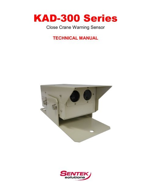
<strong>KAD</strong>-<strong>300</strong> Series<br />
Close Crane Warning Sensor<br />
TECHNICAL MANUAL
GENERAL<br />
The <strong>KAD</strong>-<strong>300</strong> close crane warning sensor is intended for use on overhead bridge cranes to prevent<br />
crane- to-wall collisions or limit the approach of adjacent cranes within the same bay. The system is a<br />
self- contained hardware unit with three separate outputs for controlling slow-down and stop zones.<br />
In addition<br />
to the three outputs, the <strong>KAD</strong>-<strong>300</strong> is<br />
equipped with a trouble (FAULT) output<br />
that will energize<br />
in the event a failure occurs with the internal infrared emitter and<br />
receiver<br />
unit.<br />
SPECIFICATIONS<br />
Type<br />
Model<br />
Power Source<br />
Power Consumption<br />
Retro-reflective infrared sensor<br />
<strong>KAD</strong>-<strong>300</strong><br />
85 to 264 VAC - 50/60Hz<br />
10VA or less when 100VAC<br />
15VA or less when 200 VAC<br />
Output Control Output – 1C Relay (250VAC 3A, 30VDC 3A) Out 1, 2, and 3<br />
Relay not energized and LED lights up when reflector is within setting distance<br />
Sensing Range<br />
Detectable Object<br />
Hysteresis<br />
Operation Mode<br />
Trouble Output – 1C Relay (250VAC 3A, 30VDC 3A) – FAULT<br />
Relay not energized 1. When light-emission amount decreases<br />
2. When light-reception amount decreases<br />
3. When Fault Occurs<br />
1 to 30 meters (100 feet) - Standard<br />
Retro-reflective Target (diamond-grade reflective surface)<br />
500mm (Approximately 20 inches)<br />
LIGHT-ON mode
Indicators<br />
Response Time<br />
Delay at Power Up<br />
Ambient Luminescence<br />
POWER – Lights up when power is ON (Green LED)<br />
OUTPUT 1,2,3 – Lights up when target is within setting distance (Orange LED)<br />
FAULT (Emitter) – Lights up when emitter strength decreases (Red LED)<br />
FAULT (Receiver) – Lights up when fault occurs (Red LED)<br />
FAULT (Receiver) - Flickers when light-reception decreases (Red LED)<br />
LEVEL – Lights up in relation to light-reception & optical alignment (5 Green LEDS)<br />
50 milliseconds or less<br />
Approximately 2 seconds<br />
Halogen and Mercury light: 10,000 lux or less<br />
Operating Conditions Temperature: -10 to +55 degrees C (14 degrees F to 130 degrees F)<br />
Relative Humidity: 85% or less (Non-condensing or frozen)<br />
Insulation Resistance<br />
Withstand Voltage<br />
100Mohm or more (Between power and contact)<br />
1,500 VAC – 1 min. (Between power and contact)<br />
Noise Resistance COM mode pulse width: 100nsec, Polarity: + and -, Phase: Phase A and B,<br />
Pulse Cycle: Power cycle 0 to 360 degrees, Pulse Voltage: 1,500V or more<br />
(By high-frequency noise simulator)<br />
Protective Structure<br />
Vibration Resistance<br />
Impact Resistance<br />
Case<br />
Metal Housing<br />
Frequency: 10 to 55 Hz, Double Amplitude: 1.5mm, Each 2 hour in X, Y and Z<br />
directions<br />
490 m/s2 (50G), Each 10 times in X, Y and Z directions<br />
SPCC<br />
Paint Munsell 5Y8/1<br />
Sensor Unit Weight<br />
Connection<br />
3 Kg (Approximately 7 lbs.)<br />
Terminal Strip<br />
CONNECTION DIAGRAM
Control Output (OUT 1, 2, and 3)<br />
Terminal Number 1 - 2 2 - 3 4 - 5 5 - 6 7 - 8 8 - 15<br />
Power-O FF State OPEN CLOSE OPEN CLOSE OPEN CLOSE<br />
Power-O N S tate (within s etting distance) OPEN CLOSE OPEN CLOSE OPEN CLOSE<br />
Power-O N S tate (over setting distanc e) CLOSE OPEN CLOSE OPEN CLOSE OPEN<br />
Trouble Output (FAULT)<br />
Terminal Number 9 - 10 10 - 11<br />
Power-O FF State OPEN CLOSE<br />
Power-ON State (normal conditions) CLOSE OPEN<br />
Power-ON State (when fault occurs) OPEN CLOSE<br />
EXTERNAL DIMENSIONS<br />
Top View<br />
Front View<br />
Side View
SET-UP PROCEDURE - Output setting switch<br />
Control Outputs (Out 1, Out 2 and 3) can be set at various distances based on requirements. The reflector is to be<br />
set at each desired distance for which an output is required to slow-down and stop the crane.<br />
1) Set the reflector at the desired distance for Output 1<br />
and push the OUT 1 switch in and hold it for 3 seconds.<br />
The Output lamp will flicker and then stop. Upon<br />
releasing the switch, the output lamp will light up to<br />
indicate that the zone has been set.<br />
2) Repeat the above procedure to set Output 2 using OUT 2.<br />
3) If Output 3 is to be set for a third zone, push both the<br />
OUT 1 and OUT 2 switches at the same time and hold<br />
for 3 seconds. Upon releasing the switches, the Output lamp<br />
will light up to indicate that a third zone has been set.<br />
Europe’s Official<br />
Distributor<br />
1010 Cambourne Business Park, Cambridge, CB23 6DP UK.<br />
Tel +44 (1223) 923 930 : Fax +44 (1223) 923 940<br />
info@sentekeurope.com : www.sentekeurope.com