GRATE-LOCK™ Grating - Grating Pacific
GRATE-LOCK™ Grating - Grating Pacific
GRATE-LOCK™ Grating - Grating Pacific
- No tags were found...

You also want an ePaper? Increase the reach of your titles
YUMPU automatically turns print PDFs into web optimized ePapers that Google loves.
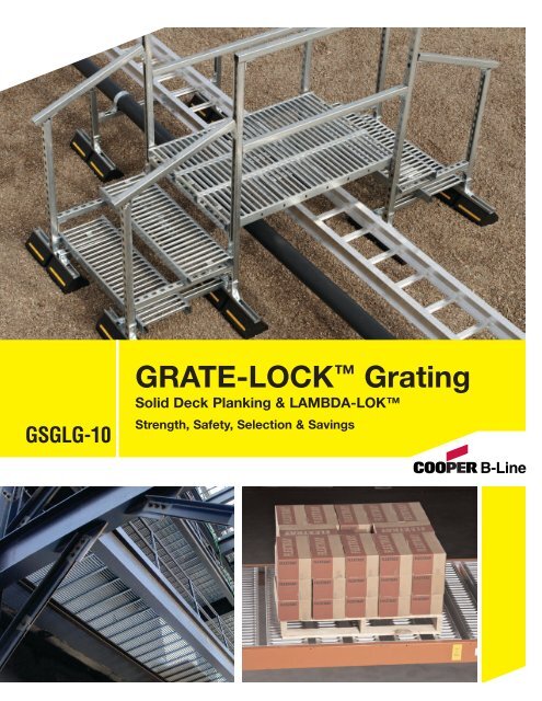
GSGLG-10<br />
<strong>GRATE</strong>-LOCK <strong>Grating</strong><br />
Solid Deck Planking & LAMBDA-LOK<br />
Strength, Safety, Selection & Savings
Table of Contents & Advantages<br />
Advantages . . . . . . . . . . . . . . . . . . . . . . . . . . . . . . . . . . . . . . . . . . . . . . . . . . . . . . . . . . . . . . . . . . . . . . . . . . . . . . . . . . . . . . . . . . . . . . . . . . . . . . . . . . . . . . . . . . . 2<br />
How to Specify . . . . . . . . . . . . . . . . . . . . . . . . . . . . . . . . . . . . . . . . . . . . . . . . . . . . . . . . . . . . . . . . . . . . . . . . . . . . . . . . . . . . . . . . . . . . . . . . . . . . . . . . . . . . . . . 2<br />
Proof of Performance . . . . . . . . . . . . . . . . . . . . . . . . . . . . . . . . . . . . . . . . . . . . . . . . . . . . . . . . . . . . . . . . . . . . . . . . . . . . . . . . . . . . . . . . . . . . . . . . . . . . . . . 3<br />
Applications . . . . . . . . . . . . . . . . . . . . . . . . . . . . . . . . . . . . . . . . . . . . . . . . . . . . . . . . . . . . . . . . . . . . . . . . . . . . . . . . . . . . . . . . . . . . . . . . . . . . . . . . . . . . . . . . . . 4<br />
Specifications . . . . . . . . . . . . . . . . . . . . . . . . . . . . . . . . . . . . . . . . . . . . . . . . . . . . . . . . . . . . . . . . . . . . . . . . . . . . . . . . . . . . . . . . . . . . . . . . . . . . . . . . . . . . . . . . 5<br />
System Components . . . . . . . . . . . . . . . . . . . . . . . . . . . . . . . . . . . . . . . . . . . . . . . . . . . . . . . . . . . . . . . . . . . . . . . . . . . . . . . . . . . . . . . . . . . . . . . . . . . . . 6-7<br />
<strong>GRATE</strong>-LOCK Loading Tables (6”, 9”, & 12” Widths)<br />
1 1 /2” Channel Height . . . . . . . . . . . . . . . . . . . . . . . . . . . . . . . . . . . . . . . . . . . . . . . . . . . . . . . . . . . . . . . . . . . . . . . . . . . . . . . . . . . . . . . . . . . . . . . . . 8-9<br />
2 1 /2” Channel Height . . . . . . . . . . . . . . . . . . . . . . . . . . . . . . . . . . . . . . . . . . . . . . . . . . . . . . . . . . . . . . . . . . . . . . . . . . . . . . . . . . . . . . . . . . . . . . 10-11<br />
3” Channel Height . . . . . . . . . . . . . . . . . . . . . . . . . . . . . . . . . . . . . . . . . . . . . . . . . . . . . . . . . . . . . . . . . . . . . . . . . . . . . . . . . . . . . . . . . . . . . . . . . 12-13<br />
4” Channel Height . . . . . . . . . . . . . . . . . . . . . . . . . . . . . . . . . . . . . . . . . . . . . . . . . . . . . . . . . . . . . . . . . . . . . . . . . . . . . . . . . . . . . . . . . . . . . . . . . 14-15<br />
Solid Deck Planking . . . . . . . . . . . . . . . . . . . . . . . . . . . . . . . . . . . . . . . . . . . . . . . . . . . . . . . . . . . . . . . . . . . . . . . . . . . . . . . . . . . . . . . . . . . . . . . . . . 16-17<br />
LAMBDA-LOK . . . . . . . . . . . . . . . . . . . . . . . . . . . . . . . . . . . . . . . . . . . . . . . . . . . . . . . . . . . . . . . . . . . . . . . . . . . . . . . . . . . . . . . . . . . . . . . . . . . . . . . . 18-19<br />
<strong>GRATE</strong>-LOCK<br />
With Sole-Gripping Dimples Without Dimples Solid Deck Planking LAMBDA-LOK<br />
• Cost-saving design<br />
• Wide range of sizes, accessories<br />
• Fast field assembly<br />
• Traction grip and plain surfaces<br />
• Choice of two standard gauges: 14 and 18<br />
Special 16 gauge is available<br />
• Solid Deck is a durable,<br />
solid surface<br />
• Low-cost installation &<br />
low maintenance<br />
• Easy to replace<br />
• Pre-galvanized with a<br />
variety of uses<br />
• LAMBDA-LOK is a durable,<br />
pre-galvanized surface<br />
• Low-cost installation &<br />
low maintenance<br />
• Easy to replace<br />
• Heavy loads over long<br />
spans<br />
• Add extra Lambda-Loks<br />
for concentrated loads<br />
2
Proof Of Performance<br />
<strong>GRATE</strong>-LOCK grating is an easy-to-install<br />
system of interlocking grating planks, treads,<br />
and accessories that provides safe, sturdy<br />
footing for mezzanine floors, platforms,<br />
walkways and other applications where<br />
non-slip performance is required. Hundreds<br />
of sole-gripping dimples insure a safe surface<br />
in all kinds of weather and environments. The<br />
grating is available textured for safer working<br />
surfaces and non-textured for wheeled traffic<br />
or rack decking.<br />
Design Improves Loading Performance<br />
The unique design of <strong>GRATE</strong>-LOCK grating provides more design options. Increased load performance<br />
(see charts pages 8-15) has been achieved through interlocking planks, stronger rung design and an<br />
expanded selection of leg heights and material gauges. <strong>GRATE</strong>-LOCK lets you specify lighter gauge steel<br />
for substantial material savings.<br />
More Sizes and Gauges<br />
<strong>GRATE</strong>-LOCK grating provides one of the broadest line of grating products of any manufacturer.<br />
• Three (3) plank width options<br />
• Four (4) plank height options<br />
• Three (3) gauge options<br />
• Lengths up to 24 feet<br />
Interlocking sections provide the strength you need for extra-wide designs.<br />
Full Line of Accessories<br />
Our line includes kickplates, hold-down clamps, attachment hardware and stair treads for complete<br />
job design.<br />
Fast Bolt-Together Assembly<br />
Helps save time in the field with Grate-Lock bolt-together slotted assemblies. Kickplates and plank<br />
sections are prepunched. For additional ease, planks can be straight, curved, or angle cut with hand<br />
tools.<br />
Specify <strong>GRATE</strong>-LOCK <strong>Grating</strong> with Confidence<br />
We have constructed our tables using the most stringent interpretation of the AISI standards. Our safe<br />
allowable loads guard against harmful local distortion as well as failure, while other manufacturers have<br />
prepared allowable load tables guarding against failure only.<br />
3
Applications<br />
<strong>GRATE</strong>-LOCK - Ideal for Various Applications<br />
<strong>GRATE</strong>-LOCK grating and stair treads are stocked in multiple locations in the United States. For the finest in Safety<br />
<strong>Grating</strong> and Stair Treads, contact Cooper B-Line or look for your local <strong>GRATE</strong>-LOCK grating distributor on the<br />
internet using www.cooperbline.com.<br />
<strong>GRATE</strong>-LOCK Roof-Top Ramps<br />
<strong>GRATE</strong>-LOCK Roof-Top Crossovers<br />
<strong>GRATE</strong>-LOCK Walkway<br />
LAMBDA-LOK Applications<br />
Rack Decks<br />
Recommended Design Practices<br />
1. These specifications are presented as a general guide to the architect or structural engineer in preparing project<br />
specifications. Allowable loads, spans and other limiting conditions presented in this catalog offer product data for<br />
use in design and construction. These products must not be used without prior structural evaluation by a qualified<br />
engineer or architect.<br />
2. All supports should provide a smooth, level, 1 1 ⁄2” minimum bearing surface (2 1 ⁄2” when using hold-down clip),<br />
free of burrs, bridging, welds or other irregularities.<br />
3. Random cut ends and diagonal or circular cut exposed edges should be banded and welded at contact points at<br />
the discretion of the design engineer.<br />
4. Bolted connections, except stair or ladder tread attachment to stringer channels, may be replaced by welded<br />
connections that develop the same strength.<br />
5. Interlocking panels must be bolted or welded together when kickplates are used.<br />
4
Architectural Specifications<br />
Specifications<br />
Part 1: General<br />
1.1 Scope - The contractor shall furnish and install <strong>GRATE</strong>-LOCK Mezzanine <strong>Grating</strong>s as specified in all areas where shown in the<br />
drawings and as specified herein.<br />
1.2 Qualifications - All <strong>GRATE</strong>-LOCK gratings and accessories, unless otherwise indicated, shall be manufactured by Cooper B-Line,<br />
and shall be installed in accordance with its current printed directions.<br />
1.3 Submittals - The contractor shall furnish shop drawings of grating layout, framing and supports, unit dimensions and<br />
sections, type and location of fasteners and welds.<br />
1.4 Storage and Handling - All materials shall be stored and handled to avoid damage. Damaged or deteriorated materials shall<br />
be removed from the premises.<br />
Part 2: Products<br />
2.1 <strong>Grating</strong> Materials<br />
a. Type: <strong>GRATE</strong>-LOCK grating<br />
b. Metal: (carbon steel) (hot dipped, mill-galvanized steel)<br />
c. Finish: (mill-galvanized before fabrication, ASTM A653)<br />
d. Metal gauge: (14-ga. steel) (16-ga./ steel special order), (18-ga. steel)<br />
e. Section width: (12”) (9”) (6”) (3”-4”-supplied FM flange only)<br />
f. Channel height: (1 1 ⁄2”) (2 1 ⁄2”) (3”) (4”)<br />
g. Standard Lengths: 12’, 20’, 24’ (other lengths to order)<br />
h. Flange options: (FM) (MM) (FF)<br />
i. Surface condition: (MG - traction grip) (MS - smooth)<br />
Part 3: Execution<br />
3.1 Condition of Surfaces - Prior to grating installation, contractor shall inspect supports for correct size, layout and alignment and verify<br />
that surfaces to relieve grating are free of debris. The contractor shall report to the design or consulting engineer or owner’s agent in<br />
writing any defects considered detrimental to proper application or grating so defects can be remedied before grating is applied.<br />
3.2 <strong>Grating</strong> Installation - Install grating in accordance with manufacturer’s recommendations and shop drawings. Position grating sections<br />
flat and square with ends bearing min. 1 1 ⁄2” on supporting structure. Keep grating sections at least 1 ⁄4” away from vertical steel sections<br />
and 1 ⁄2” from concrete walls. Allow clearance at joints between sections of max. 1 ⁄4” at side channels and max. 3 ⁄8” at ends. Band random<br />
cut ends and diagonal or circular cut exposed edges with a min. 1 ⁄8” thick bar welded at contact points.<br />
3.3 <strong>Grating</strong> Attachment - Attach grating to supports without warp or deflection as follows:<br />
a. Single plank application - Secure plank ends to supporting members at every point of contact. Use <strong>GRATE</strong>-LOCK Anchoring Devices.<br />
b. Multiple plank application - Secure plank ends to supporting members at every point of contact and intermediate grating sections<br />
with at least one attachment each end of plank on alternate sides. For added rigidity, attach side channels of adjacent plank together<br />
(at mid-point of span).<br />
c. Welded attachment - Secure side channels to supports by fusion welding with 1 ⁄8” fillet welds 1” long. Weld adjacent planks together<br />
with 1 ⁄8” fillet welds 1” long, 24” o.c. staggered top and bottom.<br />
d. Clamp and bolt attachment - Secure intermediate planks to supports using proper length hold-down clamps.<br />
Special Services<br />
Custom Fabrication - On large jobs, Cooper B-Line estimates, quotes, details and fabricates to your specifications. Quotations are made<br />
from submitted plans and specification. After receipt of order, a bill of materials and necessary layout drawings are prepared. <strong>Grating</strong> is<br />
supplied with special cutting, banding and toe plates installed where needed. Fabrication services are available through your <strong>GRATE</strong>-LOCK<br />
grating distributor.<br />
Stair Treads - Contact Cooper B-Line at the toll-free number listed below for information on standard and custom stair tread designs.<br />
Distributors - <strong>GRATE</strong>-LOCK grating for mezzanines are stocked by distributors in principal cities. Consult your local classified telephone<br />
directory under <strong>GRATE</strong>-LOCK or call Cooper B-Line for assistance.<br />
For more information call Cooper B-Line toll free: (800) 851-9341 • FAX (770) 268-7213<br />
NOTICE: We shall not be liable for incidental and consequential damages, directly or indirectly sustained, nor for any loss caused by<br />
application of these goods not in accordance with current printed instructions or for other than the intended use. Our liability is expressly<br />
limited to replacement of defective goods. Any claim shall be deemed waived unless made in writing to us within thirty (30) days from date<br />
it was or reasonably should have been discovered.<br />
Cooper B-Line Safety <strong>Grating</strong> - Safety for Every Walk of Life<br />
5
<strong>GRATE</strong>-LOCK System Components<br />
<strong>GRATE</strong>-LOCK <strong>Grating</strong> Non-Slip Components<br />
Plank Sections<br />
11/16” ± 1 /16”<br />
3/8” ± 1 /8”<br />
3/4”<br />
6” wide - 5 15 /16” ± 1 /16”<br />
9” wide - 8 15 /16” ± 1 /16”<br />
12” wide - 11 15 /16” ± 1 /16”<br />
6” wide - 4.563”<br />
9” wide - 7.563”<br />
12” wide - 10.563”<br />
6” wide - 3.812”<br />
9” wide - 6.812”<br />
12” wide - 9.812”<br />
11/16” ± 1 /16”<br />
3/8” ± 1 /8”<br />
Widths: 3”, 4”(*), 6”, 9”, 12”<br />
Heights: 1 1 /2”(**), 2 1 /2”, 3”(*), 4”(*)<br />
Gauges: 18, 16(*), 14<br />
Lengths: 12’-0”, 20’-0”, 24’-0”<br />
Other Lengths Available<br />
Note: 3” & 4” filler plank is solid. FM interlock.<br />
(*) Special quote required.<br />
(**) The 1 1 /2” product is available only in 12’-0”<br />
length and differs in side channel detail and<br />
loading capabilities. See pages 8 & 9.<br />
1 1 /2”<br />
3/4”<br />
FM<br />
FF<br />
MM<br />
3/4”<br />
1 3 /16” 1 3 /16”<br />
Stair Treads<br />
Stair treads are available in standard and custom designs.<br />
Contact Cooper B-Line at (800) 592-3643 for more information.<br />
2 1 /2”<br />
1 1 /8”<br />
7/16” x 13 /16” Slot<br />
6”, 9”, 12”<br />
2” 2”<br />
7/16” Dia.<br />
Carrier Plate<br />
Stair Tread Design<br />
and Selection Table<br />
Catalog Number<br />
T-MG62514 T-MG92514 T-MG122514<br />
Span U C U C U C<br />
2’-0” 3722 1461 2357 974 1276 730<br />
2’-6” 2382 1168 1508 974 816 730<br />
3’-0” 1654 1241 1050 974 783 730<br />
4’-0” (1) 931 931 593 889 442 730<br />
U - Uniform Load (lb/sq. ft) C - Concentrated Load (lb)<br />
(1) Intermediate stringer recommended for spans over 4<br />
6
<strong>GRATE</strong>-LOCK System Components<br />
System Components<br />
Item Product Code Height<br />
Side kickplate (14 ga.) M-SK-2514 6 1 /2”<br />
12-ft. lengths M-SK-3014 7”<br />
M-SK-4014 8”<br />
M-KC<br />
End kickplate (14 ga.) M-EK-2514 6 1 /2”<br />
12-ft. lengths M-EK-3014 7”<br />
M-EK-4014 8”<br />
Kickplate clip<br />
M-KC<br />
Hold-down clamp M-HC-25 2 1 /2”<br />
M-HC-30 3”<br />
M-HC-40 4”<br />
M-HC-15 1 1 /2”<br />
M-HC-30<br />
J-Bolt M-250J 5/16 - 2 1 /2”<br />
Tap screw (self-drilling) M-SDST-25 1/4” x 1”<br />
3/8” Hex head bolt M-100-B 3/8 - 1”<br />
with nut and washer<br />
M-250J<br />
M-SDST-25<br />
M-SK-3014<br />
M-100-B<br />
How to Specify:<br />
Plank height: (1 1 ⁄2” = 15, 2 1 ⁄2” = 25, 3” = 30, 4” = 40)<br />
Interlock detail: Female/Male<br />
MG-122518-FM<br />
Gauge: 18<br />
Plank Width: 12”<br />
<strong>Grating</strong> Surface: Specify “MG” for traction grip,<br />
“MS” for smooth surface<br />
7
<strong>GRATE</strong>-LOCK Safe Loading Tables<br />
1 1 /2” Channel Height __ 6”, 9”, & 12” Widths<br />
1/4” ± 1 /8”<br />
.080”<br />
9/16” ± 1 /8”<br />
13/16” ± 1 /16”<br />
13/16” ± 1 /16”<br />
1 7 /16” ± 1 /16”<br />
Component Availability of Galvanized Steel Panels<br />
Section Description<br />
Interlock Steel Width Standard Catalog Number (2) Wt./lin. ft. Open Area<br />
Detail Gauge Length (lbs.) (percent)<br />
12” MG-121518 2.9 45<br />
(1) 18 9” 12’ MG-91518 2.3 43<br />
6” MG-61518 1.9 39<br />
12” MG-121516 3.5 43<br />
(1) 16* 9” 12’ MG-91516 2.9 41<br />
6” MG-61516 2.3 37<br />
12” MG-121514 4.2 40<br />
(1) 14 9” 12’ MG-91514 3.5 38<br />
6” MG-61514 2.7 35<br />
(1) Specify interlock detail of panel, i.e., FM, FF or MM. Refer to general catalog (page 2) for details.<br />
(2) Traction grip surface (MG) is standard. For smooth surface replace “MG” in catalog number with “MS”.<br />
Note: Refer to page 6 for information on accessories and 2 1 ⁄2”, 3” and 4” channel height panels.<br />
* Special Order Only Consult Factory<br />
8
<strong>GRATE</strong>-LOCK Safe Loading Tables<br />
1 1 /2” Channel Height __ 6”, 9”, & 12” Widths<br />
Panel Design Loads<br />
Allowable Loads and Deflections: U=Uniform Load (3) (lb./ft. 2 ) C=Concentrated Load (4) (lb.) D=Deflection (in.)<br />
Gauge Width 2’-0” 2’-6” 3’-0” 3’-6” 4’-0” 4’-6” 5’-0” 5’-6” 6’-0” 6’-6” 7’-0” 7’-6” 8’-0” 8’-6” 9’-0” 9’-6” 10’-0” 10’-6” 11’-0” 11’-6” 12’-0”<br />
U 443 283 196 144 110 87 70 58 49 41 36 31 27 24 21 19 17 16 14 13 12<br />
D .10 .11 .14 .18 .22 .27 .33 .40 .48 .56 .65 .74 .84 .95 1.06 1.18 1.31 1.45 1.59 1.73 1.89<br />
12”<br />
C<br />
D<br />
U 591 378 263 193 147 116 94 78 65 56 48 42 37 32 29 26 23 21 19 17 16<br />
D .10 .11 .14 .18 .22 .27 .33 .40 .48 .56 .65 .74 .84 .95 1.06 1.18 1.31 1.45 1.59 1.73 1.89<br />
18 9”<br />
C 440 352 293 251 220 195 176 160 146 135 125 117 110 103 97 92 86 83 80 76 73<br />
D .04 .07 .10 .13 .17 .21 .26 .32 .38 .45 .52 .60 .68 .77 .86 .96 1.06 1.17 1.28 1.40 1.54<br />
U 890 570 395 290 222 175 142 117 99 84 72 63 55 49 44 39 35 32 29 26 24<br />
D .10 .11 .14 .18 .22 .27 .33 .40 .48 .56 .65 .74 .84 .95 1.06 1.18 1.31 1.45 1.59 1.73 1.89<br />
6”<br />
C<br />
D<br />
U 549 351 244 179 137 108 87 72 61 52 44 39 34 30 27 24 22 19 18 16 15<br />
D .10 .11 .14 .18 .22 .27 .33 .40 .48 .56 .65 .74 .84 .95 1.06 1.18 1.31 1.45 1.59 1.73 1.89<br />
12”<br />
C<br />
D<br />
U 733 469 326 239 183 144 117 97 81 69 59 52 45 40 36 32 29 26 24 22 20<br />
D .10 .11 .14 .18 .22 .27 .33 .40 .48 .56 .65 .74 .84 .95 1.06 1.18 1.31 1.45 1.59 1.73 1.89<br />
16* 9”<br />
C 546 437 364 312 273 242 218 198 182 168 156 145 136 128 121 115 109 104 99 95 91<br />
D .04 .07 .10 .13 .17 .21 .26 .32 .38 .45 .52 .60 .68 .77 .86 .96 1.06 1.17 1.28 1.40 1.54<br />
U 1104 706 490 360 276 218 176 146 122 104 90 78 69 61 54 49 44 40 36 33 30<br />
D .10 .11 .14 .18 .22 .27 .33 .40 .48 .56 .65 .74 .84 .95 1.06 1.18 1.31 1.45 1.59 1.73 1.89<br />
6”<br />
C<br />
D<br />
U 667 427 296 217 166 131 106 88 74 63 54 47 41 36 32 29 26 24 22 20 18<br />
D .10 .11 .14 .18 .22 .27 .33 .40 .48 .56 .65 .74 .84 .95 1.06 1.18 1.31 1.45 1.59 1.73 1.89<br />
12”<br />
C<br />
D<br />
U 891 570 396 291 222 176 142 117 99 84 72 63 55 49 44 39 35 32 29 27 24<br />
D .10 .11 .14 .18 .22 .27 .33 .40 .48 .56 .65 .74 .84 .95 1.06 1.18 1.31 1.45 1.59 1.73 1.89<br />
14 9”<br />
C 663 531 442 379 331 295 265 241 221 204 189 177 165 156 147 139 132 126 120 115 110<br />
D .04 .07 .10 .13 .17 .21 .26 .32 .38 .45 .52 .60 .68 .77 .86 .96 1.06 1.17 1.28 1.40 1.54<br />
U 1341 858 596 438 335 265 214 177 149 127 109 95 83 74 66 59 53 48 44 40 37<br />
D .10 .11 .14 .18 .22 .27 .33 .40 .48 .56 .65 .74 .84 .95 1.06 1.18 1.31 1.45 1.59 1.73 1.89<br />
6”<br />
C<br />
D<br />
(3) Simple or equal-length double spans; multiply uniform load values by 1.07 for three, or 1.04 for four equal-length continuous spans.<br />
Deflections shown for simple spans (all were within 1 /120th of span limitation); multiply deflection values by 0.71 for equal-length double spans,<br />
or by 0.76 for three of four equal-length continuous spans.<br />
(4) Simple spans; multiply concentrated load volumes by 1.23 for equal-length double spans, 1.17 for three, or 1.19 for four equal length<br />
continuous spans. Load(s) applied to top section, as a line across entire section width, at center of (each) span.<br />
* Special Order Only Consult Factory<br />
Span<br />
9
<strong>GRATE</strong>-LOCK Safe Loading Tables<br />
2 1 /2” Channel Height __ 6”, 9”, & 12” Widths<br />
1/4” ± 1 /8”<br />
.080”<br />
9/16” ± 1 /8”<br />
1 7 /16” ± 1 /16”<br />
1” ± 1 /16”<br />
1 3 /16”<br />
1 3 /16”<br />
Component Availability/Galvanized Steel Panels<br />
Section Description<br />
Interlock Steel Width Standard Catalog Number (2) Wt./lin. ft. Open Area<br />
Detail Gauge Length (lbs.) (percent)<br />
12” MG-122518 3.5 45<br />
(1) 18 9” 12’ MG-92518 3.0 43<br />
6” MG-62518 2.5 39<br />
12” MG-122516 4.3 43<br />
(1) 16* 9” 12’ MG-92516 3.7 41<br />
6” MG-62516 3.1 37<br />
12” MG-122514 5.2 40<br />
(1) 14 9” 12’ MG-92514 4.4 38<br />
6” MG-62514 3.7 35<br />
(1) Specify interlock detail of panel, i.e., FM, FF or MM. Refer to general catalog (page 2) for details.<br />
(2) Traction grip surface (MG) is standard. For smooth surface replace “MG” in catalog number with “MS”.<br />
Note: Refer to page 7 for information on accessories.<br />
* Special Order Only Consult Factory<br />
10
Product Selection/Design Table<br />
<strong>GRATE</strong>-LOCK Safe Loading Tables<br />
2 1 /2” Channel Height __ 6”, 9”, & 12” Widths<br />
Allowable Loads and Deflections: U=Uniform Load (lb./ft. 2 ) C=Concentrated Load (lb.) D=Deflection (in.)<br />
Clear Span (Lin.Ft.)<br />
Gauge Width Weight Cat. Load 2’-0” 3’-0” 4’-0” 5’-0” 6’-0” 7’-0” 8’-0” 9’-0” 10’-0” 11’-0” 12’-0” 13’-0” 14’-0” 15’-0” 16’-0” 17’-0” 18’-0”<br />
Lb./lin.ft. No. Type<br />
12” 3.70 MG122518<br />
18 9” 3.16 MG92518<br />
6” 2.62 MG62518<br />
12” 4.55 MG122516<br />
16* 9” 3.89 MG92516<br />
6” 3.22 MG62516<br />
12” 5.62 MG122514<br />
14 9” 4.80 MG92514<br />
6” 3.98 MG62514<br />
U 1057 552 312 200 140 103 80 64 52 43 36 31 27 23 20 18 16<br />
D 0.03 0.10 0.17 0.27 0.39 0.54 0.71 0.90 1.13 1.38 1.61 1.91 2.23 2.47 2.83 3.20 3.60<br />
C 529 529 529 501 420 362 319 286 260 239 217 207 194 184 175 167 160<br />
D 0.01 0.05 0.12 0.22 0.31 0.43 0.57 0.72 0.90 1.09 1.33 1.57 1.85 2.15 2.48 2.85 3.24<br />
U 1552 691 390 251 175 129 100 79 65 54 46 40 35 30 27 24 21<br />
D 0.05 0.10 0.18 0.28 0.41 0.56 0.74 0.95 1.18 1.44 1.73 2.05 2.41 2.80 3.22 3.69 4.01<br />
C 705 705 585 470 394 339 299 268 243 223 207 193 181 171 163 153 145<br />
D 0.02 0.07 0.14 0.23 0.33 0.45 0.59 0.76 0.94 1.15 1.38 1.64 1.93 2.24 2.58 2.91 3.27<br />
U 2141 954 538 346 241 178 137 109 89 74 63 54 47 42 37 33 30<br />
D 0.04 0.09 0.16 0.25 0.36 0.50 0.65 0.83 0.04 1.27 1.52 1.80 2.11 2.45 2.82 3.23 3.67<br />
C 1053 715 538 432 362 312 274 246 223 204 189 176 165 156 148 141 135<br />
D 0.04 0.07 0.13 0.20 0.29 0.40 0.52 0.67 0.83 1.01 1.22 1.44 1.69 1.96 2.26 2.58 2.93<br />
U 1276 655 370 238 166 123 95 76 62 52 44 37 32 28 24 22 20<br />
D 0.03 0.10 0.17 0.27 0.39 0.54 0.71 0.91 1.13 1.39 1.67 1.94 2.21 2.55 2.81 3.34 3.59<br />
C 638 638 638 595 499 432 381 342 312 285 261 241 224 209 196 184 174<br />
D 0.01 0.05 0.12 0.22 0.31 0.43 0.57 0.72 0.91 1.10 1.31 1.53 1.78 2.04 2.34 2.63 2.94<br />
U 1949 869 491 316 220 163 126 100 82 69 58 49 43 37 33 29 26<br />
D 0.05 0.10 0.18 0.29 0.41 0.57 0.75 0.96 1.19 1.46 1.76 2.05 2.39 2.69 3.16 3.48 3.92<br />
C 851 851 736 592 496 428 378 339 308 383 261 241 224 209 196 184 174<br />
D 0.02 0.09 0.15 0.23 0.33 0.45 0.60 0.76 0.95 1.17 1.40 1.64 1.90 2.19 2.48 2.77 3.15<br />
U 2774 1235 696 447 312 230 177 140 114 95 81 69 60 53 47 42 38<br />
D 0.04 0.09 0.17 0.26 0.38 0.51 0.67 0.86 1.06 1.30 1.55 1.84 2.15 2.49 2.86 3.26 3.69<br />
C 1134 926 696 559 467 402 354 316 286 262 242 225 211 198 188 178 170<br />
D 0.02 0.07 0.13 0.21 0.30 0.41 0.54 0.69 0.85 1.04 1.24 1.47 1.72 1.99 2.29 2.61 2.95<br />
U 1276 783 442 284 199 147 113 90 74 62 52 44 38 35 29 28 25<br />
D 0.03 0.10 0.17 0.27 0.39 0.54 0.71 0.91 1.13 1.38 1.63 1.94 2.20 2.70 2.92 3.58 4.08<br />
C 730 730 730 711 596 514 454 407 370 338 310 286 266 248 233 219 207<br />
D 0.01 0.05 0.12 0.22 0.31 0.43 0.57 0.72 0.90 1.09 1.31 1.53 1.77 2.04 2.33 2.63 2.96<br />
U 2357 1050 593 381 266 196 151 121 98 82 70 58 50 45 40 36 32<br />
D 0.04 0.10 0.18 0.28 0.41 0.56 0.74 0.94 1.17 1.43 1.72 1.88 2.21 2.57 2.96 3.39 3.85<br />
C 974 974 889 714 598 516 454 407 369 339 314 282 265 250 238 227 218<br />
D 0.02 0.07 0.14 0.23 0.33 0.45 0.59 0.75 0.94 1.14 1.38 1.50 1.77 2.05 2.37 2.71 3.08<br />
U 3722 1654 931 596 414 304 233 184 149 123 103 88 76 66 58 52 46<br />
D 0.05 0.10 0.18 0.29 0.42 0.56 0.74 0.93 1.15 1.39 1.65 1.93 2.25 2.57 2.91 3.32 3.70<br />
C 1461 1241 931 744 620 532 465 414 372 338 310 286 266 248 233 219 207<br />
D 0.03 0.09 0.14 0.23 0.33 0.45 0.58 0.74 0.92 1.11 1.32 1.55 1.80 2.06 2.36 2.65 2.98<br />
Notes:<br />
These tables are prepared based on test conducted in accordance with the 1980 edition, section 6.2 of the American Iron and Steel Institute<br />
Specification for the design of cold-rolled steel structural members with results checked and adjusted where required by calculations in<br />
accordance with section 2 of the same specification.<br />
Safe Allowable Loads with deflections equal to or less than L/120<br />
Safe Allowable Loads with deflections equal to or less than L/240<br />
*Special Order Only Consult Factory<br />
11
<strong>GRATE</strong>-LOCK Safe Loading Tables<br />
3” Channel Height __ 6”, 9”, & 12” Widths<br />
.080”<br />
1/4” ± 1 /8”<br />
9/16” ± 1 /8”<br />
2 15 /16” ± 1 /16”<br />
1” ± 1 /16”<br />
1 3 /16”<br />
1 3 /16”<br />
Component Availability of Galvanized Steel Panels<br />
Section Description<br />
Interlock Steel Width Standard Catalog Number (2) Wt./lin. ft. Open Area<br />
Detail Gauge Length (lbs.) (percent)<br />
12” MG-123018 3.6 45<br />
(1) 18 9” 12’ MG-93018 3.1 43<br />
6” MG-63018 2.6 39<br />
12” MG-123016 4.5 43<br />
(1) 16* 9” 12’ MG-93016 3.7 41<br />
6” MG-63016 3.2 37<br />
12” MG-123014 5.4 40<br />
(1) 14 9” 12’ MG-93014 4.7 38<br />
6” MG-63014 3.9 35<br />
(1) Specify interlock detail of panel, i.e., FM, FF or MM. Refer to general catalog (page 2) for details.<br />
(2) Traction grip surface (MG) is standard. For smooth surface replace “MG” in catalog number with “MS”.<br />
Note: Refer to page 7 for information on accessories.<br />
* Special Order Only Consult Factory<br />
12
Product Selection/Design Table<br />
<strong>GRATE</strong>-LOCK Safe Loading Tables<br />
3” Channel Height __ 6”, 9”, & 12” Widths<br />
Allowable Loads and Deflections: U=Uniform Load (lb./ft. 2 ) C=Concentrated Load (lb.) D=Deflection (in.)<br />
Clear Span (Lin.Ft.)<br />
Gauge Width Weight Cat. Load 2’-0” 3’-0” 4’-0” 5’-0” 6’-0” 7’-0” 8’-0” 9’-0” 10’-0” 11’-0” 12’-0” 13’-0” 14’-0” 15’-0” 16’-0” 17’-0” 18’-0”<br />
Lb./lin.ft. No. Type<br />
12” 3.88 MG123018<br />
18 9” 3.34 MG93018<br />
6” 2.80 MG63018<br />
12” 4.77 MG123016<br />
16* 9” 4.11 MG93016<br />
6” 3.44 MG63016<br />
12” 5.89 MG123014<br />
14 9” 5.07 MG93014<br />
6” 4.25 MG63014<br />
U 1057 611 345 222 155 114 88 70 57 48 41 35 31 27 24 22 20<br />
D 0.02 0.07 0.12 0.19 0.28 0.39 0.51 0.65 0.80 0.98 1.20 1.43 1.68 1.95 2.25 2.58 2.93<br />
C 529 529 529 529 472 405 354 316 287 263 244 229 215 203 193 184 177<br />
D 0.01 0.03 0.07 0.14 0.22 0.31 0.41 0.52 0.64 0.79 0.95 1.14 1.34 1.56 1.80 2.06 2.34<br />
U 1881 840 472 302 210 154 118 93 76 62 52 45 39 34 30 26 24<br />
D 0.03 0.08 0.13 0.21 0.31 0.42 0.55 0.68 0.86 1.01 1.21 1.43 1.70 1.93 2.23 2.47 2.81<br />
C 705 705 705 567 472 405 354 315 283 258 236 218 202 189 177 168 161<br />
D 0.01 0.04 0.11 0.17 0.24 0.33 0.44 0.55 0.68 0.82 0.98 1.15 1.32 1.52 1.74 1.97 2.24<br />
U 2834 1260 709 453 315 231 177 140 113 94 79 67 58 50 44 39 35<br />
D 0.04 0.07 0.13 0.21 0.29 0.39 0.52 0.66 0.80 0.99 1.19 1.37 1.14 1.82 2.08 2.34 2.60<br />
C 1058 945 709 567 472 405 354 315 283 258 236 218 202 189 177 167 157<br />
D 0.02 0.06 0.11 0.16 0.23 0.32 0.42 0.53 0.65 0.60 0.93 1.11 1.28 1.47 1.66 1.14 2.09<br />
U 1276 775 438 282 197 160 123 98 80 66 56 45 39 35 31 28 25<br />
D 0.02 0.07 0.12 0.20 0.28 0.45 0.59 0.75 0.93 1.13 1.35 1.43 1.69 1.96 2.27 2.61 2.97<br />
C 638 638 638 638 591 559 492 440 398 365 337 293 276 262 249 238 229<br />
D 0.01 0.03 0.07 0.05 0.23 0.36 0.47 0.60 0.74 0.90 1.08 1.15 1.35 1.57 1.82 2.09 2.38<br />
U 2275 1029 581 373 261 193 149 118 97 81 69 59 52 46 40 36 33<br />
D 0.03 0.03 0.13 0.21 0.30 0.41 0.54 0.69 0.87 1.06 1.27 1.51 1.77 2.06 2.37 2.70 3.05<br />
C 851 851 851 700 587 506 446 400 363 333 309 288 271 256 242 230 220<br />
D 0.01 0.04 0.11 0.17 0.24 0.33 0.44 0.56 0.69 0.85 1.02 1.21 1.42 1.65 1.89 2.16 2.44<br />
U 3418 1519 854 547 380 279 214 169 137 113 95 82 71 62 55 49 45<br />
D 0.03 0.07 0.12 0.20 0.28 0.39 0.50 0.64 0.79 0.95 1.13 1.34 1.56 1.81 2.08 2.37 2.68<br />
C 1134 1134 854 684 570 480 427 380 342 310 286 266 249 234 221 210 201<br />
D 0.02 0.05 0.10 0.15 0.23 0.31 0.40 0.51 0.63 0.76 0.91 1.07 1.25 1.45 1.66 1.89 2.14<br />
U 1461 950 536 345 241 178 137 109 89 74 63 54 47 42 37 33 30<br />
D 0.02 0.07 0.13 0.20 0.29 0.40 0.53 0.67 0.84 1.02 1.23 1.46 1.71 1.99 2.29 2.62 2.98<br />
C 730 730 730 730 722 622 548 491 446 409 379 353 332 314 298 284 272<br />
D 0.01 0.03 0.07 0.14 0.23 0.32 0.42 0.54 0.67 0.82 0.98 1.17 1.37 1.59 1.83 2.10 2.38<br />
U 2597 1477 831 532 369 271 208 164 133 110 92 79 68 59 52 46 41<br />
D 0.03 0.09 0.16 0.25 0.36 0.48 0.63 0.79 0.98 1.19 1.40 1.67 1.94 2.18 2.53 2.81 3.14<br />
C 974 974 974 974 831 712 623 554 498 453 415 383 356 332 311 293 277<br />
D 0.01 0.04 0.10 0.20 0.28 0.38 0.50 0.63 0.78 0.95 1.12 1.32 1.54 1.76 2.00 2.27 2.54<br />
U 4984 2215 1246 797 554 407 311 246 199 165 138 118 102 89 78 69 62<br />
D 0.04 0.09 0.15 0.24 0.34 0.46 0.60 0.76 0.94 1.14 1.35 1.60 1.85 2.12 2.42 2.72 3.05<br />
C 1461 1461 1246 997 831 712 623 554 498 453 415 383 356 332 311 293 277<br />
D 0.02 0.06 0.12 0.19 0.27 0.36 0.48 0.61 0.75 0.91 1.08 1.27 1.48 1.70 1.92 2.18 2.43<br />
Notes:<br />
These tables are prepared based on test conducted in accordance with the 1980 edition, section 6.2 of the American Iron and Steel Institute<br />
Specification for the design of cold-rolled steel structural members with results checked and adjusted where required by calculations in<br />
accordance with section 2 of the same specification.<br />
Safe Allowable Loads with deflections equal to or less than L/120<br />
Safe Allowable Loads with deflections equal to or less than L/240<br />
*Special Order Only Consult Factory<br />
13
<strong>GRATE</strong>-LOCK Safe Loading Tables<br />
4” Channel Height __ 6”, 9”, & 12” Widths<br />
1/4” ± 1 /8”<br />
.080”<br />
9/16” ± 1 /8”<br />
3 15 /16” ± 1 /16”<br />
1” ± 1 /16”<br />
1 3 /16”<br />
1 3 /16”<br />
Component Availability of Galvanized Steel Panels<br />
Section Description<br />
Interlock Steel Width Standard Catalog Number (2) Wt./lin. ft. Open Area<br />
Detail Gauge Length (lbs.) (percent)<br />
12” MG-124018 4.0 45<br />
(1) 18 9” 12’ MG-94018 3.5 43<br />
6” MG-64018 3.0 39<br />
12” MG-124016 4.9 43<br />
(1) 16* 9” 12’ MG-94016 4.3 41<br />
6” MG-64016 3.7 37<br />
12” MG-124014 5.9 40<br />
(1) 14 9” 12’ MG-94014 5.2 38<br />
6” MG-64014 4.4 35<br />
(1) Specify interlock detail of panel, i.e., FM, FF or MM. Refer to general catalog (page 2) for details.<br />
(2) Traction grip surface (MG) is standard. For smooth surface replace “MG” in catalog number with “MS”.<br />
Note: Refer to page 7 for information on accessories.<br />
* Special Order Only Consult Factory<br />
14
Product Selection/Design Table<br />
<strong>GRATE</strong>-LOCK Safe Loading Tables<br />
4” Channel Height __ 6”, 9”, & 12” Widths<br />
Allowable Loads and Deflections: U=Uniform Load (lb./ft. 2 ) C=Concentrated Load (lb.) D=Deflection (in.)<br />
Clear Span (Lin.Ft.)<br />
Gauge Width Weight Cat. Load 2’-0” 3’-0” 4’-0” 5’-0” 6’-0” 7’-0” 8’-0” 9’-0” 10’-0” 11’-0” 12’-0” 13’-0” 14’-0” 15’-0” 16’-0” 17’-0” 18’-0”<br />
Lb./lin.ft. No. Type<br />
12” 4.24 MG124018<br />
18 9” 3.70 MG94018<br />
6” 3.16 MG64018<br />
12” 5.21 MG124016<br />
16* 9” 4.55 MG94016<br />
6” 3.89 MG64016<br />
12” 6.49 MG124014<br />
14 9” 5.62 MG94014<br />
6” 4.80 MG64014<br />
U 1057 996 560 359 249 183 140 111 90 74 62 53 46 40 35 31 28<br />
D 0.03 0.06 0.11 0.16 0.24 0.34 0.42 0.54 0.66 0.81 0.96 1.09 1.26 1.45 1.65 1.90 2.11<br />
C 529 529 529 529 529 529 529 498 448 408 374 345 320 299 280 264 249<br />
D 0.00 0.01 0.04 0.08 0.13 0.21 0.32 0.44 0.53 0.65 0.77 0.87 1.01 1.17 1.33 1.50 1.68<br />
U 1881 1329 747 478 332 244 187 148 120 99 83 71 61 53 47 41 37<br />
D 0.02 0.06 0.12 0.18 0.26 0.35 0.47 0.58 0.72 0.86 1.03 1.21 1.41 1.60 1.83 2.05 2.34<br />
C 705 705 705 705 705 641 560 498 448 408 374 345 320 299 280 264 249<br />
D 0.01 0.02 0.06 0.12 0.20 0.28 0.36 0.46 0.57 0.70 0.83 0.96 1.12 1.28 1.47 1.65 1.85<br />
U 4232 1993 1121 717 498 366 280 221 179 148 125 106 92 80 70 62 55<br />
D 0.03 0.06 0.10 0.18 0.25 0.34 0.44 0.55 0.69 0.83 0.99 1.17 1.35 1.54 1.77 1.98 2.24<br />
C 1058 1058 1058 897 747 641 560 498 448 408 374 345 320 299 280 264 249<br />
D 0.01 0.04 0.08 0.13 0.19 0.26 0.35 0.45 0.55 0.67 0.80 0.93 1.07 1.24 1.41 1.60 1.78<br />
U 1276 1215 685 439 306 226 173 138 112 93 79 69 60 53 47 42 37<br />
D 0.03 0.06 0.11 0.17 0.25 0.34 0.45 0.51 0.71 0.86 1.03 1.11 1.29 1.49 1.71 1.95 2.20<br />
C 638 638 638 638 638 638 638 619 560 512 472 450 420 395 373 354 337<br />
D 0.00 0.01 0.04 0.08 0.14 0.21 0.33 0.46 0.57 0.69 0.83 0.89 1.03 1.20 1.37 1.56 1.76<br />
U 2275 1612 907 580 403 296 227 179 145 120 101 86 75 66 58 52 47<br />
D 0.02 0.06 0.10 0.16 0.24 0.37 0.48 0.60 0.75 0.91 1.07 1.27 1.48 1.71 1.96 2.22 2.51<br />
C 851 851 851 851 851 777 680 604 544 495 453 420 393 369 348 330 314<br />
D 0.01 0.02 0.05 0.10 0.18 0.29 0.38 0.49 0.60 0.73 0.86 1.01 1.18 1.37 1.56 1.78 2.01<br />
U 5118 2418 1360 870 604 444 340 269 218 180 151 129 111 97 85 75 67<br />
D 0.02 0.06 0.10 0.16 0.22 0.30 0.40 0.51 0.63 0.76 0.90 1.05 1.22 1.41 1.59 1.80 2.02<br />
C 1134 1134 1134 1088 907 777 680 604 544 495 453 418 389 363 340 320 302<br />
D 0.01 0.03 0.07 0.12 0.18 0.25 0.32 0.41 0.50 0.60 0.72 0.85 0.98 1.13 1.28 1.44 1.61<br />
U 1461 1448 814 521 362 266 204 161 131 109 92 79 69 61 54 48 43<br />
D 0.01 0.06 0.10 0.16 0.24 0.32 0.42 0.54 0.67 0.82 0.98 1.16 1.35 1.57 1.80 2.06 2.33<br />
C 730 730 730 730 730 730 730 724 655 599 554 515 483 455 430 409 391<br />
D 0.00 0.01 0.04 0.07 0.12 0.20 0.30 0.43 0.54 0.65 0.78 0.93 1.08 1.26 1.44 1.65 1.87<br />
U 2597 1988 1120 719 501 369 284 225 184 153 129 111 96 84 75 67 60<br />
D 0.02 0.06 0.11 0.17 0.25 0.34 0.44 0.57 0.70 0.85 0.02 1.21 1.41 1.63 1.88 2.14 2.42<br />
C 974 974 974 974 974 969 852 761 688 629 581 540 505 475 449 426 406<br />
D 0.01 0.02 0.05 0.10 0.17 0.27 0.36 0.45 0.56 0.68 0.82 0.97 1.13 1.31 1.50 1.71 1.93<br />
U 5843 2895 1629 1042 724 532 407 322 261 215 181 154 133 116 102 91 82<br />
D 0.03 0.06 0.12 0.19 0.28 0.37 0.48 0.61 0.75 0.91 1.08 1.26 1.47 1.69 1.92 2.19 2.48<br />
C 1461 1461 1461 1303 1086 931 814 724 651 592 513 501 465 434 407 386 367<br />
D 0.01 0.04 0.09 0.15 0.21 0.30 0.39 0.49 0.60 0.73 0.87 1.01 1.18 1.35 1.54 1.75 1.98<br />
Notes:<br />
These tables are prepared based on test conducted in accordance with the 1980 edition, section 6.2 of the American Iron and Steel Institute<br />
Specification for the design of cold-rolled steel structural members with results checked and adjusted where required by calculations in<br />
accordance with section 2 of the same specification.<br />
Safe Allowable Loads with deflections equal to or less than L/120<br />
Safe Allowable Loads with deflections equal to or less than L/240<br />
*Special Order Only Consult Factory<br />
15
Solid Deck Planking<br />
Solid deck planking provides the flexibility of a medium weight and a smooth surface. Manufactured with the same<br />
interlocking system of <strong>GRATE</strong>-LOCK, Solid deck locks into place for quick installation. Use Solid deck in areas<br />
where a solid, sturdy covering surface is needed. Available in a wide variety of gauges and special quote options.<br />
Solid Deck Planking Features<br />
• Durable, pre-galvanized solid surface • Available in widths of 6”, 9”, and 12”<br />
• Quick, low-cost installation • Available in heights of 1 1 /2” and 2 1 /2”<br />
• Easy to replace • Available in lengths of 12’-0”, 20’-0”, 24’-0”<br />
• Minimum maintenance<br />
• Standard 14 gauge steel<br />
• Accessories available<br />
• Applications include rack decking, filler planks, and light-load flooring<br />
• Other gauges, widths, and lengths are available by special order. On large jobs, Cooper B-Line estimates, details,<br />
and fabricates to your specifications.<br />
How to Specify:<br />
Plank height: (1 1 ⁄2” = 15, 2 1 ⁄2” = 25, 3” = 30, 4” = 40)<br />
Interlock detail: Female/Male<br />
SD-122518-FM<br />
Gauge: 18<br />
Plank Width: 12”<br />
<strong>Grating</strong> Surface: “SD” for solid deck,<br />
16
Solid Deck Planking<br />
** Profile for 1 1 /2”<br />
Channel Depth<br />
Interlocking Options for<br />
2 1 /2” Channel Depth<br />
Specify interlock detail of<br />
panel, i.e., FM, FF or MM.<br />
Refer to general catalog<br />
(page 2) for details<br />
FM<br />
FF<br />
MM<br />
Standard Accessories<br />
Clear Span (Lin.Ft.)<br />
Channel Catalog Weight Load<br />
Depth Gauge Width Number Lb./lin.ft. Type<br />
2’-0” 3’-0” 4’-0” 5’-0” 6’-0” 7’-0” 8’-0” 9’-0” 10’-0” 11’-0” 12’-0”<br />
12” SD-121514 4.5<br />
1 1 /2”** 14 9” SD-91514 3.7<br />
6” SD-61514 2.9<br />
U 316 296 166 106 74 54 41 32 26 22 18<br />
D 0.03 0.14 0.22 0.33 0.48 0.65 0.84 1.06 1.31 1.59 1.89<br />
C 158 158 158 158 158 158 158 147 132 120 110<br />
D 0.01 0.03 0.08 0.16 0.27 0.44 0.65 0.86 1.06 1.28 1.54<br />
U 420 398 222 142 99 72 55 44 35 29 24<br />
D 0.03 0.14 0.22 0.33 0.48 0.65 0.85 1.06 1.31 1.59 1.89<br />
C 211 211 211 211 211 189 165 147 132 120 110<br />
D 0.01 0.05 0.11 0.21 0.37 0.52 0.68 0.86 1.06 1.28 1.54<br />
U 690 596 335 214 149 109 83 66 53 44 37<br />
D 0.03 0.06 0.10 0.18 0.25 0.34 0.44 0.55 0.69 0.83 0.99<br />
C 344 344 331 265 221 189 165 147 132 120 110<br />
D 0.02 0.07 0.17 0.26 0.38 0.52 0.68 0.86 1.06 1.28 1.54<br />
12” SD-122514 5.8<br />
2 1 /2” 14 9” SD-92514 5.0<br />
U 316 316 316 284 199 147 113 90 74 62 52<br />
D 0.01 0.04 0.13 0.27 0.39 0.54 0.71 0.91 1.13 1.38 1.63<br />
C 158 158 158 158 158 158 158 158 158 158 158<br />
D 0.01 0.01 0.03 0.04 0.08 0.13 0.19 0.28 0.39 0.52 0.67<br />
U 420 420 420 381 266 196 151 121 98 82 70<br />
D 0.01 0.04 0.13 0.28 0.41 0.56 0.74 0.94 1.17 1.43 1.72<br />
C 211 211 211 211 211 211 211 211 211 211 211<br />
D 0.01 0.01 0.03 0.07 0.11 0.18 0.27 0.38 0.52 0.69 0.90<br />
U 690 690 690 596 414 304 233 184 149 123 103<br />
D 0.01 0.04 0.14 0.29 0.42 0.56 0.74 0.93 1.15 1.39 1.65<br />
6” SD-62514 4.2<br />
C 344 344 344 344 344 344 344 344 344 338 310<br />
D 0.01 0.02 0.05 0.11 0.18 0.29 0.43 0.62 0.85 1.11 1.32<br />
Notes:<br />
These tables are prepared based on tests conducted in accordance with the 1986 edition, section F.1 of the American Iron and Steel Institute<br />
Specification for the design of cold-rolled steel structural members with the results checked and adjusted where required by calculations in<br />
accordance with section A5 of the same specification.<br />
Safe Allowable Loads with deflections equal to or less than L/120<br />
Safe Allowable Loads with deflections equal to or less than L/240<br />
Bold Print values designate loads/deflections limited due to ‘Strut Loading’<br />
U = Allowable Simple Span Uniform Load (lb./ft. 2 ) C = Allowable Simple Span Concentrated Line Load (lb.) at Midspan<br />
D = Vertical Deflection (in.) at Midspan<br />
17
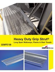
LAMBDA-LOK - Solid Mezzanine & Industrial Flooring<br />
LAMBDA-LOK is a solid steel plank flooring that does not duplicate conventional grating. It is no longer necessary to<br />
have slots and holes for reinforcing the top surface that prohibit wheel use on elevated or mezzanine floors. Small<br />
wheels roll freely on LAMBDA-LOK’s strong ribbed surface.<br />
The load bearing lok will lock the solid steel planks together without the need for nuts, bolts, or crimping tools by<br />
twisting into place with pliers. Patented, positive attachment, holds planks in place, and provide an “unlocking”<br />
feature for later removal or replacement.<br />
Fast Installation<br />
Male/male planks assemble fast and can be spliced anywhere, even in the field, and require fewer support members.<br />
See chart on page 19.<br />
LAMBDA-LOK Application<br />
View from below<br />
View from above<br />
LAMBDA-LOK Features<br />
• Designed for carts and two wheelers (not recommended for pallet movers)<br />
• Simple low-cost installation - no nuts or bolts! Twist into place with a pliers<br />
• Will handle heavy loads over long spans<br />
• Durable, pre-galvanized surface with minimum maintenance<br />
• Extra load bearing loks can be added for concentrated loads<br />
• Easy to replace if section is damaged<br />
• Applications include mezzanines, catwalks, sub-floors, walkways, and inverted ceilings<br />
18
LAMBDA-LOK - Solid Mezzanine & Industrial Flooring<br />
1 7 /8”<br />
2” 2”<br />
11 3 /4”<br />
LAMBDA-LOK Plank<br />
2” 2” 1 7 /8”<br />
6” typ. 3”<br />
6”<br />
2 1 /2”<br />
7/16”<br />
End View<br />
18 Ga. Material<br />
1 1 /32”<br />
3 1 /4”<br />
Splice<br />
Channel<br />
1 1 /4”<br />
5”<br />
3/4”<br />
15/16” 15/16”<br />
3 3 /4”<br />
Planks to be spliced<br />
Side View & Slot Detail<br />
Load Bearing Lok<br />
Load Bearing Lok<br />
15/16”<br />
Splicing LAMBDA-LOK Ends<br />
Step 1. Install load bearing lok in the end<br />
slot of the first LAMBDA-LOK plank<br />
using a pliers to snap in place<br />
Step 2. Slip splice channel in place over<br />
the installed load bearing lok<br />
Step 3. Push up splice channel and install<br />
second load bearing lok in the second<br />
LAMBDA-LOK plank<br />
Splice is completed<br />
Step 1<br />
Step 2<br />
Step 3<br />
12 1 /2”<br />
3/4”<br />
Completed Splice<br />
Allowable Load Capacities (Safety Factor 1.5)<br />
Span 2’-0” 3’-0” 4’-0” 5’-0” 6’-0” 7’-0” 8’-0”<br />
C 1604 1069 802 642 535 458 401<br />
D c .03 .07 .12 .18 .26 .36 .45<br />
W (Wheel) 300 300 300 300 256 219 192<br />
U 1637 728 409 262 182 134 102<br />
D u .01 .08 .15 .23 .33 .45 .58<br />
Notes<br />
U - Allowable Uniform Load (lbs./sq.ft.)<br />
C - Allowable Concentrated Line Load at Midspan (lbs.)<br />
D - Deflection at Midspan (in.)<br />
W - Allowable Wheel Load Simulated by a 1 1 /2” x 1” Point Load at Mid-Width and Midspan (lbs.)<br />
LAMBDA-LOK Spacing<br />
Spacing should be 12” on center for most applications<br />
Splicing Conditions<br />
To maintain allowable loads when splicing, the following conditions must be met:<br />
1. Outer most panels must be spliced at supports only<br />
2. Inner panels can be spliced anywhere, including midspan, providing the distance between<br />
splices\connections of adjacent panels equals or exceeds the support spacing<br />
19
Global Locations<br />
Cooper B-Line’s U.S. Customer Service Service Facility - Canada: Cooper B-Line - Saudia Arabia:<br />
Center is staffed Monday through Friday from Cooper B-Line - Canada PO Box 70160 - Al Khobar - 31952<br />
7 a.m. to 5:00 p.m. Central Standard Time. Div. of Cooper Ind. Canada, Inc. Kingdom of Saudia Arabia<br />
If a situation requires that you have to contact 5925 McLaughlin Road Phone: 00966 3 812 2236<br />
us after hours, please leave a message via Mississauga, ON L5R 1B8 Fax: 00966 3 812 1291<br />
phone or E-mail so we can give it immediate Canada Email: blineme@cooperindustries.com<br />
attention the following business day. Phone: (800) 569-3660<br />
Fax: (888) 753-3355<br />
Literature Fulfillment Questions:<br />
Service Facility - United States: Email: blinecanada@cooperindustries.com Phone: (314) 426-1800<br />
Cooper B-Line - USA Fax: (314) 426-6022<br />
509 West Monroe Street Service Facility - Europe: Email: cooperbline@repcographics.com<br />
Highland, IL 62249<br />
Cooper B-Line, Ltd. - UK<br />
United States Walrow, Highbridge Request Literature Website:<br />
Phone: (800) 851-7415 Somerset, TA9 4AQ http://order.repcographics.com/cooperb/<br />
Fax: (800) 356-1438<br />
United Kingdom<br />
Email: blineus@cooperindustries.com Phone: + 44 (0) 1278 783371<br />
Fax: + 44 (0) 1278 789037<br />
Email: sales@cooperbline.co.uk<br />
U.S. Customer Service<br />
Cooper B-Line<br />
509 West Monroe Street<br />
Highland, IL 62249<br />
Phone: 800-851-9341<br />
Fax: 770-268-7213<br />
Cooper Industries, Plc.<br />
600 Travis, Ste. 5600<br />
Houston, TX 77002-1001<br />
Phone: 713-209-8400<br />
www.cooperindustries.com<br />
© 2010 Cooper B-Line, Inc. GSGLG-10 Printed in U.S.A. 10610