1.1.1. The squirt height difference must not exceed 21% (10% flow ...
1.1.1. The squirt height difference must not exceed 21% (10% flow ...
1.1.1. The squirt height difference must not exceed 21% (10% flow ...

You also want an ePaper? Increase the reach of your titles
YUMPU automatically turns print PDFs into web optimized ePapers that Google loves.
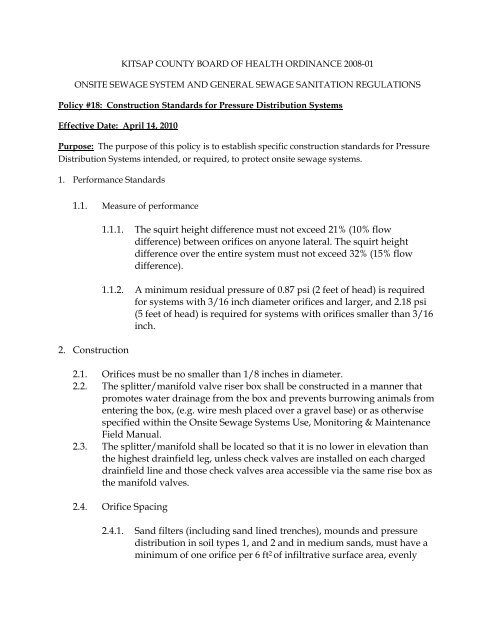
KITSAP COUNTY BOARD OF HEALTH ORDINANCE 2008-01<br />
ONSITE SEWAGE SYSTEM AND GENERAL SEWAGE SANITATION REGULATIONS<br />
Policy #18: Construction Standards for Pressure Distribution Systems<br />
Effective Date: April 14, 2010<br />
Purpose: <strong>The</strong> purpose of this policy is to establish specific construction standards for Pressure<br />
Distribution Systems intended, or required, to protect onsite sewage systems.<br />
1. Performance Standards<br />
1.1. Measure of performance<br />
2. Construction<br />
<strong>1.1.1.</strong> <strong>The</strong> <strong>squirt</strong> <strong>height</strong> <strong>difference</strong> <strong>must</strong> <strong>not</strong> <strong>exceed</strong> <strong>21%</strong> (<strong>10%</strong> <strong>flow</strong><br />
<strong>difference</strong>) between orifices on anyone lateral. <strong>The</strong> <strong>squirt</strong> <strong>height</strong><br />
<strong>difference</strong> over the entire system <strong>must</strong> <strong>not</strong> <strong>exceed</strong> 32% (15% <strong>flow</strong><br />
<strong>difference</strong>).<br />
1.1.2. A minimum residual pressure of 0.87 psi (2 feet of head) is required<br />
for systems with 3/16 inch diameter orifices and larger, and 2.18 psi<br />
(5 feet of head) is required for systems with orifices smaller than 3/16<br />
inch.<br />
2.1. Orifices <strong>must</strong> be no smaller than 1/8 inches in diameter.<br />
2.2. <strong>The</strong> splitter/manifold valve riser box shall be constructed in a manner that<br />
promotes water drainage from the box and prevents burrowing animals from<br />
entering the box, (e.g. wire mesh placed over a gravel base) or as otherwise<br />
specified within the Onsite Sewage Systems Use, Monitoring & Maintenance<br />
Field Manual.<br />
2.3. <strong>The</strong> splitter/manifold shall be located so that it is no lower in elevation than<br />
the highest drainfield leg, unless check valves are installed on each charged<br />
drainfield line and those check valves area accessible via the same rise box as<br />
the manifold valves.<br />
2.4. Orifice Spacing<br />
2.4.1. Sand filters (including sand lined trenches), mounds and pressure<br />
distribution in soil types 1, and 2 and in medium sands, <strong>must</strong> have a<br />
minimum of one orifice per 6 ft 2 of infiltrative surface area, evenly
distributed.<br />
2.4.2. In other soil types, there <strong>must</strong> be a minimum of one orifice every six<br />
feet on center along the lateral.<br />
2.4.3. <strong>The</strong> maximum spacing between the outside laterals and the edge of<br />
the trench or bed <strong>must</strong> be 1/2 of the selected orifice spacing, ±0.5 feet.
Table A-1 Lateral Design Table<br />
Maximum Lateral Length<br />
(ft)<br />
Orifice Lateral Orifice<br />
Spacing<br />
Pipe Material<br />
(inches) (inches) (feet) Schedule 40<br />
1/8 1 1.5 42<br />
1/8 1 2 50<br />
1/8 1 2.5 57.5<br />
1/8 1 3 66<br />
1/8 1 4 80<br />
1/8 1 5 90<br />
1/8 1 6 102<br />
1/8 1.25 1.5 66<br />
1/8 1.25 2 80<br />
1/8 1.25 2.5 92.5<br />
1/8 1.25 3 105<br />
1/8 1.25 4 124<br />
1/8 1.25 5 145<br />
1/8 1.25 6 162<br />
1/8 1.5 1.5 85.5<br />
1/8 1.5 2 104<br />
1/8 1.5 2.5 120<br />
1/8 1.5 3 135<br />
1/8 1.5 4 164<br />
1/8 1.5 5 190<br />
1/8 1.5 6 210<br />
1/8 2 1.5 132<br />
1/8 2 2 160<br />
1/8 2 2.5 185<br />
1/8 2 3 207<br />
1/8 2 4 248<br />
1/8 2 5 290<br />
1/8 2 6 324<br />
5/32 1 1.5 31.5<br />
5/32 1 2 36<br />
5/32 1 2.5 42.5
5/32 1 3 48<br />
Table A-1 Lateral Design Table (continued)<br />
Maximum Lateral Length<br />
(ft)<br />
Orifice Lateral Orifice<br />
Spacing<br />
Pipe Material<br />
(inches) (inches) (feet) Schedule 40<br />
5/32 1 4 56<br />
5/32 1 5 65<br />
5/32 1 6 72<br />
5/32 1 1/4 1.5 48<br />
5/32 1 1/4 2 58<br />
5/32 1 1/4 2.5 67.5<br />
5/32 1 1/4 3 75<br />
5/32 1 1/4 4 92<br />
5/32 1 1/4 5 105<br />
5/32 1 1/4 6 120<br />
5/32 1 1/2 1.5 63<br />
5/32 1 1/2 2 76<br />
5/32 1 1/2 2.5 87.5<br />
5/32 1 1/2 3 99<br />
5/32 1 1/2 4 120<br />
5/32 1 1/2 5 140<br />
5/32 1 1/2 6 156<br />
5/32 2 1.5 96<br />
5/32 2 2 116<br />
5/32 2 2.5 135<br />
5/32 2 3 150<br />
5/32 2 4 184<br />
5/32 2 5 210<br />
5/32 2 6 240<br />
3/16 1 1.5 24<br />
3/16 1 2 28<br />
3/16 1 2.5 32.5<br />
3/16 1 3 39<br />
3/16 1 4 44
3/16 1 5 50<br />
3/16 1 6 60<br />
3/16 1.25 1.5 37.5
Table A-1 Lateral Design Table (continued)<br />
Maximum Lateral Length<br />
(ft)<br />
Orifice Lateral Orifice<br />
Spacing<br />
Pipe Material<br />
(inches) (inches) (feet) Schedule 40<br />
3/16 1.25 2 46<br />
3/16 1.25 2.5 52.5<br />
3/16 1.25 3 60<br />
3/16 1.25 4 72<br />
3/16 1.25 5 85<br />
3/16 1.25 6 96<br />
3/16 1.5 1.5 49.5<br />
3/16 1.5 2 60<br />
3/16 1.5 2.5 70<br />
3/16 1.5 3 78<br />
3/16 1.5 4 92<br />
3/16 1.5 5 110<br />
3/16 1.5 6 120<br />
3/16 2 1.5 76.5<br />
3/16 2 2 92<br />
3/16 2 2.5 105<br />
3/16 2 3 120<br />
3/16 2 4 144<br />
3/16 2 5 165<br />
3/16 2 6 186<br />
7/32 1 1.5 19.5<br />
7/32 1 2 24<br />
7/32 1 2.5 27.5<br />
7/32 1 3 30<br />
7/32 1 4 36<br />
7/32 1 5 45<br />
7/32 1 6 48<br />
7/32 1.25 1.5 31.5<br />
7/32 1.25 2 38<br />
7/32 1.25 2.5 42.5<br />
7/32 1.25 3 48
7/32 1.25 4 60<br />
7/32 1.25 5 70<br />
Table A-1 Lateral Design Table (continued)<br />
Maximum Lateral Length<br />
(ft)<br />
Orifice Lateral Orifice Spacing Pipe Material<br />
(inches) (inches) (feet) Schedule 40<br />
7/32 1.25 6 78<br />
7/32 1.5 1.5 40.5<br />
7/32 1.5 2 50<br />
7/32 1.5 2.5 57.5<br />
7/32 1.5 3 63<br />
7/32 1.5 4 76<br />
7/32 1.5 5 90<br />
7/32 1.5 6 102<br />
7/32 2 1.5 63<br />
7/32 2 2 76<br />
7/32 2 2.5 87.5<br />
7/32 2 3 99<br />
7/32 2 4 116<br />
7/32 2 5 135<br />
7/32 2 6 156<br />
1/4 1 1.5 16.5<br />
1/4 1 2 20<br />
1/4 1 2.5 22.5<br />
1/4 1 3 27<br />
1/4 1 4 32<br />
1/4 1 5 35<br />
1/4 1 6 42<br />
1/4 1.25 1.5 27<br />
1/4 1.25 2 32<br />
1/4 1.25 2.5 37.5<br />
1/4 1.25 3 42<br />
1/4 1.25 4 48<br />
1/4 1.25 5 55<br />
1/4 1.25 6 66<br />
1/4 1.5 1.5 34.5
1/4 1.5 2 42<br />
1/4 1.5 2.5 47.5<br />
Table A-1 Lateral Design Table (continued)<br />
Maximum Lateral Length<br />
(ft)<br />
Orifice Lateral Orifice Spacing Pipe Material<br />
(inches) (inches) (feet) Schedule 40<br />
1/4 1.5 3 54<br />
1/4 1.5 4 64<br />
1/4 1.5 5 75<br />
1/4 1.5 6 84<br />
1/4 2 1.5 52.5<br />
1/4 2 2 64<br />
1/4 2 2.5 72.5<br />
1/4 2 3 81<br />
1/4 2 4 100<br />
1/4 2 5 115<br />
1/4 2 6 126