Chapter 9: Rapid Spanning Tree Protocol (RSTP) - E+C Spot On
Chapter 9: Rapid Spanning Tree Protocol (RSTP) - E+C Spot On
Chapter 9: Rapid Spanning Tree Protocol (RSTP) - E+C Spot On
- No tags were found...

You also want an ePaper? Increase the reach of your titles
YUMPU automatically turns print PDFs into web optimized ePapers that Google loves.
<strong>Chapter</strong> 9: <strong>Rapid</strong> <strong>Spanning</strong> <strong>Tree</strong> <strong>Protocol</strong> (<strong>RSTP</strong>)<br />
9.1 Introduction<br />
In practice, STP can actually take anything from 30 to 50 s to<br />
re-converge following a topology change. In order to provide<br />
a faster recovery, the IEEE introduced <strong>Rapid</strong> <strong>Spanning</strong> <strong>Tree</strong><br />
<strong>Protocol</strong> (<strong>RSTP</strong>) (IEEE 802.1w) – having backwards compatibility<br />
with STP.<br />
Probably the most important feature introduced by 802.1w<br />
is rapid transition. <strong>RSTP</strong> provides significantly faster spanning<br />
tree convergence – responding to a topology change within<br />
3×Hello times (3 × 2 s (default|)) or a few milliseconds of a<br />
physical link failure.<br />
Whilst the legacy STP waited passively for the network to converge<br />
before it turned a port into the forwarding state, <strong>RSTP</strong> is<br />
able to actively confirm that a port can safely transition to the<br />
forwarding state without having to rely on any timer configuration.<br />
As opposed to STP, <strong>RSTP</strong> clearly distinguishes between the<br />
state of a port and the role of a port.<br />
9.2 <strong>RSTP</strong> port states<br />
Whilst, as previously described, STP defines five port states,<br />
<strong>RSTP</strong> defines only three: Forwarding; Learning; and a new<br />
state, Discarding.<br />
Discarding describes a port where all the received frames<br />
are discarded and no learning takes place. There are thus no<br />
entries in the filtering database that point to this port and no traffic<br />
being forwarded across it.<br />
9.3 <strong>RSTP</strong> port roles<br />
Whereas STP defines the port roles of designated and root,<br />
<strong>RSTP</strong> adds three new port roles: Disabled (formally defined as<br />
a port state in STP); Backup port; and Alternate port. In STP<br />
these latter two new roles would have been called blocked.<br />
A backup port is paralleled to a designated port such that if<br />
a switch has a designated port to a particular collision domain,<br />
and has a second port connecting to that same collision domain,<br />
the port is declared a backup port. This is detected by<br />
the switch as it senses its own Configuration BPDU arriving on<br />
that port.<br />
An alternate port is essentially a backup to the root port: if<br />
the root port is lost, the alternate port is quickly used as the new<br />
root port<br />
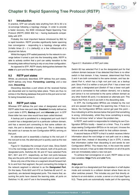
Figure 9.1 illustrates the concept of port roles. Since Switch<br />
14 is the root bridge switch in this network, both of its ports are<br />
designated ports. Switches 82, 65 and 47 have selected Ports<br />
82/1, 65/1 and 47/1, respectively, as their root ports because<br />
they are the ports with the lowest root path cost on each switch.<br />
Since only one of the links on a segment should forward traffic<br />
to and from that segment, the port connecting this bridge to<br />
the network segment is referred to as the Designated Port.<br />
<strong>On</strong> this basis, Ports 82/2 and 47/2 on Switches 82 and 47, respectively,<br />
are declared designated ports. This means that, assuming<br />
the ports have cleared the learning state, all ports on<br />
Switches 14, 82, and 47 are in the forwarding state.<br />
Figure 9.1: Illustration of RST port roles.<br />
Switch 65 has selected Port 3 as the designated port for that<br />
collision domain because it has detected that there is no other<br />
switch in that domain. It has, however, determined that Ports<br />
3 and 4 are both connected to the same domain, and has declared<br />
Port 4, which has a high root port cost, as a backup<br />
port. Since Port 2 is neither a root port (Port 1 has a lower root<br />
path cost); a designated port (Switch 47 has a lower root path<br />
cost and is connected to that collision domain); nor a backup<br />
port (since it is not connected to the same collision domain as<br />
any other Switch 65 port); it is declared an alternate port. This<br />
means that Ports 4 and 2 are both in the discarding state.<br />
In STP, the Configuration BPDUs are initiated by the root<br />
and are passed down through the spanning tree. If there is a<br />
failure, the Configuration BPDUs cannot get past this point –<br />
thus indicating to all the devices below that point that something<br />
is wrong. Unfortunately, whilst they know something is wrong<br />
they do not know ‘what’ or ‘where’ the problem lies.<br />
In <strong>RSTP</strong>, each switch is responsible for initiating its own Configuration<br />
BPDUs locally – based on a timer. Thus, if a switch<br />
stops seeing Configuration BPDUs on its root port, it knows the<br />
failure is with the designated switch for that collision domain.<br />
A second feature of <strong>RSTP</strong> is that if a switch receives inferior<br />
information about the root bridge or root path cost on a designated<br />
port then, instead of discarding it (as in STP), it stores<br />
that information (rather than discarding it) and sends its own<br />
Configuration BPDU. This means that, in the event the switch<br />
loses its root port, it has up-to-date information on all of its ports<br />
and can immediately select a new root port.<br />
To achieve fast convergence on a port, <strong>RSTP</strong> relies on two<br />
new variables: Edge Ports and Link Ports.<br />
Edge ports<br />
An edge port is a designated port that operates in a half-duplex<br />
mode and connects to a collision domain where there are no<br />
other switches present. This includes any port that directly attaches<br />
to an end-station, a router, a server or a hub (see Figure<br />
9.2). These ports are automatically made part of the spanning<br />
Industrial Communications Handbook • June 2013
<strong>Chapter</strong> 9: <strong>Rapid</strong> <strong>Spanning</strong> <strong>Tree</strong> <strong>Protocol</strong> (<strong>RSTP</strong>)<br />
tree and transition directly to the forwarding state – skipping<br />
the listening and learning stages, regardless of what happens<br />
on the other ports. A switch can automatically detect an edge<br />
port by noting the absence of Configuration BPDUs from any<br />
attached system. Alternatively, it can be manually configured by<br />
the network administrator.<br />
Figure 9.2: Example of edge port operating in a half-duplex<br />
mode and connecting to a hub, a collision domain where no<br />
other switches are present.<br />
Link ports<br />
Ports that are not edge ports are referred to as link ports and<br />
participate in the spanning tree process.<br />
In switched networks, most links operate in full-duplex mode<br />
and are thus treated as point-to-point links by <strong>RSTP</strong>, which can<br />
only achieve rapid transition to the forwarding state on edge<br />
ports and on point-to-point links. The link port is automatically<br />
derived from the duplex mode of a port. A port that operates in<br />
full-duplex is assumed to be point-to-point, while a half-duplex<br />
port is considered as a shared port by default.<br />
9.4 Fast recovery<br />
Fast network recovery on <strong>RSTP</strong> encompasses a wide range of<br />
mechanisms.<br />
If a designated port fails on a switch having a backup port,<br />
it engages immediately without fear of forming a loop since the<br />
switch still has the lowest root path cost for that collision domain,<br />
regardless of the number of switches attached to it. If either a<br />
root port or a designated port fails, and it is in half duplex mode<br />
(e.g., attached to a hub), then the original STP is engaged.<br />
For point-to-point link ports: if failure occurs on a designated<br />
port, the responsibility for recovery lies with the switches in the<br />
tree below the failure; with the switch actually experiencing the<br />
failure no longer providing the designated port for that collision<br />
domain.<br />
In the event of a root port failure (e.g., the port physically<br />
goes offline or it stops seeing Configuration BPDUs from the<br />
up-tree switch), a switch immediately places all the designated<br />
ports into the discarding state to prevent loops from forming. It<br />
selects its next best port to be the new root port – moving it into<br />
the learning state on its way to forwarding. It then sends a Configuration<br />
BPDU proposal on all of its other link ports.<br />
This configuration BPDU notifies the surrounding switches<br />
and gives them an opportunity to reconfigure. However, switches<br />
receiving the Configuration BDPU on a backup, alternate,<br />
or designated port will not change their configuration since, if<br />
they were not using the switch that detected the loss to get to<br />
the root bridge previously, they will certainly not use it when it<br />
changes to a worse path.<br />
The only switches of concern are those receiving the Configuration<br />
BDPU on their root port – who immediately place their<br />
designated ports into discarding state; select a new root port;<br />
and respond to the original switch with a Configuration BPDU<br />
response.<br />
The original switch can thus reconfigure and determine<br />
which roles to assign to which ports, on a port-by-port basis,<br />
with no fear of forming loops.<br />
This essentially creates a cascading effect, away from the<br />
root bridge, down through the spanning tree, which is redeployed<br />
with no need for any switch to wait in a listening state. In<br />
effect, no switch activates a port until it is certain that that port<br />
cannot participate in a loop. This is a major aspect that allows<br />
<strong>RSTP</strong> to achieve faster convergence times than STP.<br />
<strong>RSTP</strong> maintains backup details regarding the discarding status<br />
of ports – thus avoiding timeouts if the current forwarding<br />
ports were to fail or BPDUs were not received on the root port<br />
within a certain interval.<br />
9.5 Summary<br />
In summary, <strong>RSTP</strong> provides significantly faster spanning tree<br />
convergence than STP. As distinct from STP, <strong>RSTP</strong> assumes<br />
that the three STP port states (listening, blocking and disabled)<br />
are all the same and do not forward frames or learn MAC addresses.<br />
Hence, <strong>RSTP</strong> places them all into a new state called<br />
discarding state. Learning and forwarding ports remain more or<br />
less the same.<br />
Furthermore, unlike STP, where bridges only send out a<br />
BDPU when they see one on their root port, <strong>RSTP</strong>-enabled<br />
switches send out BPDUs every Hello time, containing current<br />
information.<br />
And finally, whilst STP defines only two port types (root and<br />
designated), <strong>RSTP</strong> includes two additional port types – alternate<br />
ports and backup ports. An alternate port has an alternative<br />
path, or parts, to the root but is currently in a discarding<br />
state (and may be considered as an additional unused root<br />
port). A backup port can be considered as an additional unused<br />
designated port.<br />
Industrial Communications Handbook • June 2013