Goniometer - Frederiksen
Goniometer - Frederiksen
Goniometer - Frederiksen
- No tags were found...

You also want an ePaper? Increase the reach of your titles
YUMPU automatically turns print PDFs into web optimized ePapers that Google loves.
Instruction Manual<br />
No. 012-08904A<br />
<strong>Goniometer</strong><br />
PS-2138, PS-2137
<strong>Goniometer</strong><br />
Model No. PS-2138<br />
Contents<br />
Introduction . . . . . . . . . . . . . . . . . . . . . . . . . . . . . . . . . . . . . . . . . . . . . . . . . . . . . . . . . 3<br />
Probe Mounting . . . . . . . . . . . . . . . . . . . . . . . . . . . . . . . . . . . . . . . . . . . . . . . . . . . . . . 4<br />
Sensor Setup . . . . . . . . . . . . . . . . . . . . . . . . . . . . . . . . . . . . . . . . . . . . . . . . . . . . . . . . 5<br />
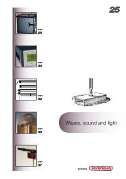
Suggested Activities . . . . . . . . . . . . . . . . . . . . . . . . . . . . . . . . . . . . . . . . . . . . . . . . . . 6<br />
Experiment . . . . . . . . . . . . . . . . . . . . . . . . . . . . . . . . . . . . . . . . . . . . . . . . . . . . . . . . . . 9<br />
Experiment Teachers' Notes and Sample Data . . . . . . . . . . . . . . . . . . . . . . . . . . . . 19<br />
Other Sample Data. . . . . . . . . . . . . . . . . . . . . . . . . . . . . . . . . . . . . . . . . . . . . . . . . . . 23<br />
Safety . . . . . . . . . . . . . . . . . . . . . . . . . . . . . . . . . . . . . . . . . . . . . . . . . . . . . . . . . . . . . 25<br />
Specifications. . . . . . . . . . . . . . . . . . . . . . . . . . . . . . . . . . . . . . . . . . . . . . . . . . . . . . . 25<br />
Technical Support . . . . . . . . . . . . . . . . . . . . . . . . . . . . . . . . . . . . . . . . . . . . . . . . . . . 25<br />
Copyright . . . . . . . . . . . . . . . . . . . . . . . . . . . . . . . . . . . . . . . . . . . . . . . . . . . . . . . . . . 25<br />
Limited Warranty . . . . . . . . . . . . . . . . . . . . . . . . . . . . . . . . . . . . . . . . . . . . . . . . . . . . 25
PS-2139<br />
ANGLE<br />
SENSOR<br />
ä<br />
Model No. PS-2138<br />
<strong>Goniometer</strong><br />
<strong>Goniometer</strong><br />
PS-2137, PS-2138<br />
1 2<br />
Angle Sensor<br />
Probe<br />
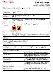
Equipment Included<br />
Probe<br />
Mounting straps (two small, one large)<br />
Angle Sensor (included in PS-2137 only)<br />
Part Number<br />
PS-2138<br />
PS-2547<br />
PS-2139<br />
Model PS-2137 includes probe, straps and angle sensor; model PS-2138 includes probe and straps only.<br />
Required or Optional Equipment<br />
PASPORT Interface (required)<br />
Second <strong>Goniometer</strong> Probe (optional)<br />
See PASCO catalog or www.pasco.com<br />
PS-2138<br />
Introduction<br />
With the PASPORT <strong>Goniometer</strong> students can analyze<br />
motions such as walking, running, throwing and<br />
kicking. They can also explore the physics of rotational<br />
dynamics using their arms and legs as experimental<br />
apparatus.<br />
The <strong>Goniometer</strong>, in conjunction with a PASPORT<br />
interface, measures and records the angle, angular<br />
velocity and angular acceleration of an elbow, knee or<br />
hip. The sensor can be used with a single <strong>Goniometer</strong><br />
Mounting Straps<br />
®<br />
3
<strong>Goniometer</strong><br />
Probe Mounting<br />
Probe (included) or with an optional second probe to measure two joints<br />
simultaneously. You can use multiple sensors together to support even<br />
more probes. The probe is easily attached to the body using the included<br />
hook-and-loop mounting straps.<br />
The <strong>Goniometer</strong> Probe consists of two arms and a potentiometer. As the<br />
angle between the arms changes, the resistance of the potentiometer<br />
changes. The Angle Sensor, connected to the probe, measures the<br />
resistance of the potentiometer and converts it to an angle measurement.<br />
The sensor also calculates the angular velocity and angular acceleration<br />
from the rate at which the angle changes. The data is sent digitally to your<br />
PASPORT interface at up to 100 samples per second.<br />
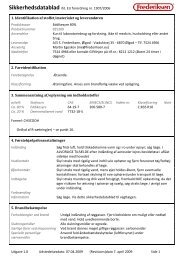
The probe measures zero degrees (or radians) when it is<br />
fully open. A clockwise rotation of the narrow arm relative<br />
to the wide arm (as pictured) is measured as increasing<br />
angle.<br />
Angle<br />
Probe Mounting<br />
The mounting straps can be used in two ways. The easier method is to<br />
place the straps on the limbs, then stick the probe to the outside of the<br />
straps. For more secure attachment, tuck the probe arms inside the<br />
overlapping portions of the straps.<br />
When mounting the <strong>Goniometer</strong> probe, the wide and narrow arms of the<br />
probe are interchangeable; the only difference will be the sign of the data<br />
collected. Attach the wide arm of the probe to the subject’s upper arm when<br />
used on the left elbow, and to the subject’s forearm when used on the right<br />
elbow. This will result in a flexion of either joint measured as a positive<br />
displacement. Similar reversals can be applied to knee and hip mounting.<br />
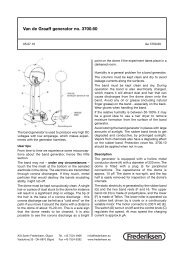
Elbow<br />
Place one strap around the<br />
upper arm midway between<br />
the elbow and shoulder.<br />
Place a second strap around<br />
the lower arm midway<br />
between the elbow and wrist.<br />
Increasing<br />
Angle<br />
With the hand relaxed, bend<br />
Right<br />
the elbow at a right angle.<br />
Align the probe’s hinge with<br />
the elbow. Attach one arm of<br />
the probe to the subject’s upper arm parallel to the humerus.<br />
Extend the elbow and attach the other probe arm parallel to the ulna. Flex<br />
and extend the elbow a few times to check for proper alignment.<br />
Increasing<br />
Angle<br />
Left<br />
4 ®
Model No. PS-2138 Sensor Setup<br />
Knee<br />
Place the large strap around the thigh just above the knee. Place<br />
a small strap around the upper part of the calf (combine both<br />
small straps end-to-end if necessary).<br />
Bend the knee at a right angle. Align the probe’s hinge with the<br />
knee. Attach one arm of the probe to the thigh parallel to the<br />
femur.<br />
Extend the knee and attach the other probe arm parallel to the<br />
tibia.<br />
Flex and extend the knee to check for proper alignment. Have<br />
the subject stand on both feet and make sure that the probe does<br />
not shift significantly.<br />
Hip<br />
Place the large strap around the waist. Combine both small<br />
straps end-to-end (if necessary) and place them around the<br />
upper thigh.<br />
Have the subject stand and place his or her foot on a chair so<br />
that the thigh is horizontal. Align the probe’s hinge with the<br />
hip joint. Attach one arm of the probe to the thigh parallel to<br />
the tibia.<br />
Have the subject stand on both feet; attach the other probe arm<br />
vertically to the waist strap.<br />
Move the hip joint through its full range of forward and<br />
backward rotation to check for proper alignment.<br />
Sensor Setup<br />
Connect one or two <strong>Goniometer</strong> Probes to the Angle Sensor. Connect the<br />
Angle Sensor to a PASPORT interface. The interface will collect data for<br />
angle, angular velocity, and angular acceleration from each probe. You can<br />
select units of degrees or radians in the software.<br />
The default sampling rate of the sensor is 20 Hz. In most cases this is<br />
sufficient, but for faster movements you may wish to increase the rate to 50<br />
or 100 Hz.<br />
Optional Data Smoothing<br />
The sensor calculates the angular velocity and angular acceleration from<br />
the measured angle data. The angular velocity is the change in angle<br />
between consecutive samples divided by the time between samples.<br />
®<br />
5
<strong>Goniometer</strong><br />
Suggested Activities<br />
Angular acceleration is the change between consecutive velocity<br />
calculations divided by the time between samples.<br />
The <strong>Goniometer</strong> is very sensitive to small variations in the angular<br />
velocity, so you may see a lot of variation in angular acceleration. To make<br />
the angular acceleration data easier for students to interpret, use the smooth<br />
function (in DataStudio) or reduce/smooth averaging (Xplorer GLX). See<br />
DataStudio online help or the GLX users’ manual for details.<br />
Optional Calibration<br />
The <strong>Goniometer</strong> does not normally require calibration. To increase the<br />
accuracy of measurements made over a limited range of motion, the<br />
<strong>Goniometer</strong> may be manually calibrated. In DataStudio, click the Calibrate<br />
button in the Experiment Setup window. Set the probe at a known angle,<br />
enter the angle under Point 1 and click the Set button. Set the probe at<br />
another known angle, enter the angle under Point 2 and click the Set<br />
button.<br />
Suggested Activities<br />
Analysis of Gait and other motions<br />
Collect angle data of the knee while walking. Does it approximate simple<br />
harmonic motion Explain what you observe.<br />
Collect angle data of the hips during walking, fast walking and running.<br />
• How does the angle of forward rotation compare to the angle of<br />
backward rotation<br />
• Compare the left and right hips. Are they symmetrical<br />
• Compare the range of movement and period of oscillation for walking,<br />
fast walking and running What patterns do you observe<br />
• Compare data from different students walking at the same speed (walk<br />
side-by-side or use a motion sensor to monitor speed).<br />
• For that class, make histograms of range of motion and period of<br />
oscillation. Do any patterns emerge<br />
• Make graphs of range of motion and period vs. height. Is there a<br />
correlation<br />
Measure the period of the leg swinging freely and compare it to the period<br />
of oscillation when the subject is walking at his or her most comfortable<br />
pace. For the class, investigate the relationship between leg length, L, and<br />
walking period, T. For all pendulums T∝<br />
L; is this true for human legs*<br />
Analyze non-periodic movements such as throwing, kicking, and lifting.<br />
When performing the movements, move only the joint that is being<br />
measured. You can collect data on the linear motion of lifted, kicked and<br />
*For a detailed<br />
analysis of the leg<br />
as a physical<br />
pendulum see: A.<br />
Dumont and C.<br />
Waltham, 1997,<br />
Walking, The<br />
Physics Teacher,<br />
35 (6): 372–376.<br />
6 ®
Model No. PS-2138 Suggested Activities<br />
thrown objects using Photogate Tape (ME-6664), a Photogate (ME-9204B)<br />
and a Digital Adapter (PS-2159).<br />
Collect data from two or more joints simultaneously while walking,<br />
running, jumping, throwing, kicking, etc. How do the joints work together<br />
when performing these actions<br />
Oscillations<br />
Collect data for the following:<br />
• Lower leg freely dangling about the knee showing simple harmonic<br />
motion, subject seated on a high surface.<br />
• Leg with unbent knee freely dangling about the hip, subject standing on<br />
the opposite foot on a low surface.<br />
• Leg with knee bent at right angle freely dangling about the hip.<br />
Do angle, angular velocity, and angular acceleration approximate simple<br />
harmonic motion Determine the period, frequency and amplitude of the<br />
oscillations.<br />
What is the relationship between the phases of angle, angular velocity, and<br />
angular acceleration<br />
How does bending the knee affect the frequency of the dangling leg<br />
Skeletal Parts<br />
Mount the <strong>Goniometer</strong> on articulated skeletal parts. In conjunction with<br />
force sensors attached with string the points of tendon attachment, measure<br />
the forces exerted by muscles when lifting objects of various mass, or<br />
performing throwing and kicking movements.<br />
®<br />
7
<strong>Goniometer</strong><br />
Suggested Activities<br />
8 ®
Model No. PS-2138<br />
<strong>Goniometer</strong><br />
Experiment<br />
In this activity you will rotate your arm about your elbow and investigate<br />
how the position, velocity and acceleration of your hand relate to the<br />
angle, angular velocity and angular acceleration of your arm.<br />
Equipment<br />
<strong>Goniometer</strong> Probe<br />
Angle Sensor<br />
PASPORT interface or interfaces<br />
(one multi-port interface or two single port interfaces)<br />
Motion Sensor<br />
Acceleration Sensor<br />
Part Number<br />
PS-2138<br />
PS-2139<br />
See PASCO catalog or www.pasco.com<br />
PS-2103<br />
PS-2118, PS-2119 or PS-2136<br />
Wall-mounted white board and pen<br />
Part 1: Arc Length vs. Angle<br />
When you rotate your forearm about your elbow (while keeping your upper<br />
arm stationary) your hand traces out an arc, or part of a circle. You will use<br />
a pen and white board to mark the path of your hand. The <strong>Goniometer</strong> will<br />
measure the angle through which your forearm rotates.<br />
Setup<br />
1. Connect the <strong>Goniometer</strong> to the interface.<br />
2. Mount the <strong>Goniometer</strong> on your elbow* so that a flexion of the joint is<br />
measured as a positive angular displacement (as pictured below).<br />
Right<br />
Left<br />
*If you are righthanded,<br />
mount the<br />
<strong>Goniometer</strong> on your<br />
right elbow; if you<br />
are left-handed,<br />
mount it on your left<br />
elbow.<br />
Flex<br />
Extend<br />
3. Stand next to the white board with your arm relaxed at your side. Let<br />
your elbow and the back of your hand touch the board.<br />
®<br />
9
<strong>Goniometer</strong><br />
Experiment<br />
4. Place a pen in your hand (as shown) so that<br />
you will draw on the board while keeping<br />
the back of your hand closest to the board.<br />
5. Have a partner mark the location of your<br />
elbow on the board, and measure the<br />
distance from your elbow to the pen.<br />
Distance from elbow to pen<br />
It is important not to twist your hand in order<br />
to allow your arm to rotate in a plane parallel<br />
to the board.<br />
Draw an arc by<br />
flexing your elbow<br />
q<br />
Mark the<br />
location of<br />
your elbow<br />
and keep it<br />
stationary<br />
Procedure<br />
1. Fully extend your elbow and place the pen tip on the board.<br />
2. Start data collection.<br />
3. Draw an arc on the board by flexing your elbow. Move only your<br />
forearm and hand, while keeping your elbow at the marked location on<br />
the board.<br />
4. Stop data collection.<br />
10 ®
Model No. PS-2138 Experiment<br />
Analysis<br />
1) Look at the graph of Angle vs. Time. According to the graph, what<br />
angle in radians did you trace out on the board<br />
Arc Angle =<br />
2) When measured in radians, the arc angle (θ) is the ratio of the arc<br />
length (s) to radius (r). In this case r is the distance from your elbow to<br />
the pen.<br />
θ = s ⁄ r<br />
According to this theoretical relationship, and your measured values of<br />
θ and r, how far did your hand travel<br />
s =<br />
(theoretical)<br />
3) Measure the length of the arc that you drew and record it below. (Tape a<br />
piece of string to the board exactly over the arc. Mark the endpoints of<br />
the arc on the string, then un-tape the string, lay it straight on a table,<br />
and measure the distance between the marks.)<br />
s =<br />
(actual)<br />
4) How does the theoretical value of s compare to the actual distance that<br />
your hand traveled<br />
®<br />
11
<strong>Goniometer</strong><br />
Experiment<br />
Part 2: Tangential Velocity vs. Angular Velocity<br />
When you rotate your forearm about the elbow, your hand does not move<br />
in a straight line, but it always moves in a direction perpendicular to your<br />
forearm. This direction is described as tangential.<br />
As you rotate your arm, the magnitude of your hand’s tangential velocity<br />
(v T<br />
) equals the change in the arc length traced by your hand (∆s) divided by<br />
the change in time (∆t)<br />
v T<br />
= ∆s ⁄ ∆t<br />
The angular velocity (ω) of your forearm equals the change in angle (∆θ)<br />
divided by the change in time (∆t).<br />
ω = ∆θ ⁄ ∆t<br />
In Part 1, you discovered that the relationship between arc length and angle<br />
is s = r θ, thus:<br />
∆s = r ∆θ<br />
Predict<br />
You will use the Motion Sensor to measure the tangential velocity of your<br />
hand, and the <strong>Goniometer</strong> to measure the angular velocity of your forearm.<br />
Based on the above equations, write an equation predicting what you will<br />
discover about the relationship between v T<br />
and ω.<br />
Setup<br />
1. Connect the <strong>Goniometer</strong> and Motion Sensor to the interface (or<br />
interfaces).<br />
2. Place the <strong>Goniometer</strong> on your elbow so that a flexion of the joint is<br />
measured as a positive angular displacement.<br />
12 ®
Model No. PS-2138 Experiment<br />
3. Mount the Motion Sensor in front of<br />
you at shoulder level and about<br />
60 cm from your chest.<br />
4. Hold your arm (as shown in the<br />
picture) so that your forearm will<br />
rotate in a horizontal plane with your<br />
hand in front of the Motion Sensor.<br />
Procedure<br />
1. Start data collection.<br />
2. While keeping your shoulder still, bend your elbow to move your hand<br />
toward the Motion Sensor, then move your hand back toward your<br />
chest. (Don't let your hand get closer than 15 cm from the sensor.)<br />
3. Stop data collection.<br />
Analysis<br />
In this analysis, use units of m/s for velocity and rad/s for angular velocity.<br />
1) Look at graphs of Velocity vs. Time and Angular Velocity vs. Time<br />
together. How are the two graphs related<br />
2) Create a graph of Velocity vs. Angular Velocity.* Qualitatively<br />
describe the graph.<br />
*Plot Velocity on the<br />
vertical axis and<br />
Angular Velocity on<br />
the horizontal axis.<br />
3) Apply a linear fit to the graph. What is the slope of the best-fit line<br />
Include units.*<br />
Slope =<br />
®<br />
*When determining<br />
the units, remember<br />
to consider the<br />
definition of a<br />
radian. Though a<br />
radian is usually<br />
used as a unit of<br />
measure, it is<br />
actually a unitless<br />
quantity. Thus m/rad<br />
is equivalent to m.<br />
13
<strong>Goniometer</strong><br />
Experiment<br />
4) Write the equation of the best-fit line in terms of v T<br />
, ω and slope. Does<br />
the relationship represented by this equation support the prediction that<br />
you made earlier<br />
5) What physical quantity is represented by the slope Measure this<br />
quantity directly and compare it to the value of slope.<br />
14 ®
Model No. PS-2138 Experiment<br />
Part 3: Centripetal and Tangential Accelerations<br />
When your forearm rotates about your elbow the velocity of your hand is<br />
entirely in the tangential direction, but the acceleration is not. There are<br />
two components to the acceleration of your hand: tangential (perpendicular<br />
to your forearm), and centripetal (parallel to your forearm.) You will use<br />
the Acceleration Sensor to measure both components.<br />
The magnitude of tangential acceleration (a T<br />
) is equal to the change in<br />
magnitude of tangential velocity (∆v T<br />
) divided by the change in time (∆t).<br />
a T<br />
= ∆v T<br />
⁄∆t<br />
The angular acceleration (α) of your forearm equals the change in angular<br />
velocity (∆ω) divided by the change in time (∆t).<br />
α = ∆ω ⁄ ∆t<br />
In Part 2, you discovered that the relationship between tangential velocity<br />
and angular velocity is v T<br />
= r ω, thus:<br />
∆v T<br />
= r ∆ω<br />
Predict<br />
You will use the Acceleration Sensor to measure the tangential acceleration<br />
of your hand, and the <strong>Goniometer</strong> to measure the angular acceleration of<br />
your forearm. Based on the above equations, write an equation predicting<br />
what you will discover about the relationship between a T<br />
and α.<br />
Setup<br />
1. Connect the <strong>Goniometer</strong> and Acceleration Sensor to the interface (or<br />
interfaces).<br />
2. Set the sample rates of both sensors to 20 Hz.<br />
3. Place the <strong>Goniometer</strong> on your elbow so that a flexion of the joint is<br />
measured as a positive angular displacement.<br />
®<br />
15
<strong>Goniometer</strong><br />
Experiment<br />
Left<br />
Right<br />
X<br />
Y<br />
Y<br />
X<br />
4. Hold the Acceleration Sensor in your hand with the sensor's X-axis<br />
parallel to your forearm and pointing toward your elbow, and the<br />
Y-axis orthogonal to your forearm and pointing in the direction that<br />
your hand moves when you flex your elbow (as shown in the picture).<br />
5. Measure the distance, r, from your elbow to the Acceleration Sensor.<br />
r =<br />
6. Hold your arm so that your forearm will rotate in a horizontal plane (as<br />
pictured), and the X-Y plane of the Acceleration Sensor is also<br />
horizontal.<br />
Procedure<br />
1. Extend your elbow.<br />
2. Start data collection.<br />
3. Quickly flex your elbow, wait a moment, then quickly extend your<br />
elbow.*<br />
4. Stop data collection.<br />
*The Acceleration<br />
Sensor must remain<br />
level (its X-Y plane<br />
parallel to the floor)<br />
throughout data<br />
collection.<br />
16 ®
Model No. PS-2138 Experiment<br />
Analysis<br />
In this analysis, use units of m/s/s or m/s 2 for acceleration, rad/s for<br />
angular velocity, and rad/s/s or rad/s 2 for angular acceleration.<br />
Tangential Acceleration<br />
1) Look at graphs of Angular Acceleration vs. Time and Tangential<br />
Acceleration vs. Time together.* How are the graphs related<br />
*Tangential<br />
Acceleration is<br />
measured by the<br />
sensor as<br />
“Acceleration, Y.”<br />
2) Create a graph of Tangential Acceleration vs. Angular Acceleration<br />
and apply a linear fit.* What is the slope of the best-fit line (including<br />
units)<br />
3) Write the equation of the best fit line in terms of a T<br />
, α and slope. Does<br />
the relationship represented by the best-fit line support the prediction<br />
that you made earlier<br />
*Plot Tangential<br />
Acceleration on the<br />
vertical axis and<br />
Angular Acceleration<br />
on the horizontal<br />
axis.<br />
4) What physical quantity is represented by the slope Measure this<br />
quantity directly and compare it to the value of slope.<br />
®<br />
17
<strong>Goniometer</strong><br />
Experiment<br />
Centripetal Acceleration<br />
5) Look at graphs of Angular Velocity vs. Time and Centripetal<br />
Acceleration vs. Time together.* How are the graphs related<br />
*Centripetal<br />
Acceleration is<br />
measured by the<br />
sensor as<br />
“Acceleration, X.”<br />
6) The Acceleration Sensor was oriented so that acceleration toward the<br />
elbow was measured as positive. When the angular velocity of your<br />
arm was positive, was the centripetal acceleration of your hand toward<br />
or away from your elbow<br />
7) When the angular velocity of your arm was negative, was the<br />
centripetal acceleration of your hand toward or away from your<br />
elbow<br />
8) Create a graph of Centripetal Acceleration vs. Angular Velocity.*<br />
The theoretical relationship between Centripetal Acceleration (a C<br />
) and<br />
Angular Velocity (ω) is a C<br />
= r ω 2 , where r is a constant. Does your data<br />
appear to support this relationship Explain your reasoning.<br />
*Plot Centripetal<br />
Acceleration on the<br />
vertical axis and<br />
Angular Velocity on<br />
the horizontal axis.<br />
9) Create a graph of a C<br />
versus ω 2 . Apply a linear fit. According to the<br />
slope of the best-fit line, what is the value of r (including units)<br />
r = (from best-fit line)<br />
10) Compare this value to the distance from your elbow to the acceleration<br />
sensor.<br />
18 ®
Model No. PS-2138 Experiment Teachers' Notes and Sample Data<br />
Experiment Teachers' Notes and Sample Data<br />
Part 1<br />
In this example r = 0.38 m.<br />
1) Arc Angle, θ = 1.42 rad<br />
2) s = r θ = (0.38 m) (1.42 rad) = 0.54 m, theoretical<br />
3) s = 0.57 m, actual<br />
4) In this example the theoretical and actual values of s differ by 5%.<br />
Part 2<br />
Students should predict v T<br />
= rω<br />
1) The graphs of Velocity vs. Time and Angular Velocity vs. Time appear<br />
to be directly proportional.<br />
®<br />
19
<strong>Goniometer</strong><br />
Experiment Teachers' Notes and Sample Data<br />
2) The graph of Velocity vs. Angular Velocity shows a directly<br />
proportional, linear relationship.<br />
3) In this example slope = 0.333 m ± 0.005 m<br />
4) v T<br />
= slope × ω<br />
v T<br />
= (0.333 m) ω<br />
This equation supports the prediction.<br />
5) Slope is r, the distance from the elbow to the hand. In this case the<br />
actual value of r is 0.36 m. The theoretical value (from slope) and<br />
actual value (from direct measurement) differ by about 8%.<br />
Note that the directly measured values of r in Part 1 and Part 2 are<br />
slightly different, though they are from the same student. This is due to<br />
the different hand positions used in each part.<br />
Part 3<br />
Students should predict a T<br />
= rα<br />
1) The graphs of Angular Acceleration vs. Time and Tangential<br />
Acceleration vs. Time appear to be directly proportional.<br />
20 ®
Model No. PS-2138 Experiment Teachers' Notes and Sample Data<br />
2) In this example, the slope of the best fit line is 0.29 m ± 0.01 m.<br />
3) a T<br />
= slope × α<br />
a T<br />
= (0.29 m) α<br />
This equation supports the prediction.<br />
4) Slope is equal to r. In this case the actual value is 0.36 m. The<br />
theoretical value (from slope) and actual value (from direct<br />
measurement) differ by about 24%.<br />
5) The graphs of Angular Velocity vs. Time and Centripetal Acceleration<br />
vs. Time appear to show a proportionality between a C<br />
and the<br />
magnitude of ω.<br />
6) When ω was positive, a C<br />
was also positive, therefor the centripetal<br />
acceleration was toward the elbow.<br />
®<br />
21
<strong>Goniometer</strong><br />
Experiment Teachers' Notes and Sample Data<br />
7) When ω was negative, a C<br />
was positive, therefor the centripetal<br />
acceleration was toward the elbow.<br />
8) In theory, the graph of a C<br />
versus ω is a parabola. Though the data<br />
contains a lot of scatter, that relationship is evident in the collected<br />
data.<br />
9) On the graph of a C<br />
versus ω 2 , the slope of the best-fit line is the<br />
theoretical value of r, in this case 0.232 m ± 0.008 m.<br />
10) The theoretical and actual values of r differ by about 55%.<br />
In Part 3, your students will probably find that the values of r according to<br />
the best-fit lines differ significantly from the actual value; and that the<br />
graphs themselves contain significant scatter or noise.<br />
Have them compare the different sensors, procedures, and mathematics<br />
(including the calculations done inside the sensor) used in each part of the<br />
22 ®
Model No. PS-2138 Other Sample Data<br />
experiment, and consider how these factors contribute to precision and<br />
accuracy of the collected data.<br />
Other Sample Data<br />
Simple Harmonic Motion of the leg rotating about the hip, dangling freely<br />
and oscillating at its natural frequency, with the knee unbent (top) and bent<br />
(bottom). Note the higher frequency of the leg with bent knee.<br />
®<br />
23
<strong>Goniometer</strong><br />
Other Sample Data<br />
Hip angle while waking at a normal pace (top) and walking quickly<br />
(bottom). Note the difference in frequency and amplitude.<br />
The angle (top) and angular velocity (bottom) of the hip while walking.<br />
The maximum slope of the angle plot is about 1.9 rad/s, equal to the<br />
maximum value of angular velocity.<br />
Angle data from the knee (top) and hip (bottom) of a walking subject,<br />
acquired using two probes simultaneously. Note the phase relationship<br />
between the joints.<br />
24 ®
Model No. PS-2138<br />
<strong>Goniometer</strong><br />
Safety<br />
Read the instructions before using this<br />
product. Students should be supervised by<br />
their instructors. When using this product,<br />
follow the instructions in this manual and<br />
all local safety guidelines that apply to<br />
you.<br />
Ensure that students are aware of these<br />
safety precautions before using the<br />
<strong>Goniometer</strong>.<br />
Place the mounting straps on the body<br />
snugly but not too tightly. The straps<br />
should not constrict blood flow or<br />
breathing. Remove all straps at the first<br />
sign of discomfort.<br />
When performing physical activities such<br />
as walking or running, do so only at a<br />
comfortable rate. Some activities call for<br />
students to stand or sit on raised surfaces;<br />
use only surfaces that are safe and<br />
appropriate for these activities.<br />
Specifications<br />
PS-2138 <strong>Goniometer</strong> Probe used with<br />
PS-2139 Angle Sensor and a PASPORT<br />
interface.<br />
Range -170°–170°<br />
Accuracy<br />
Resolution 0.04°<br />
±1° calibrated<br />
±3° uncalibrated<br />
Technical Support<br />
For assistance with any PASCO product,<br />
contact PASCO at:<br />
Address: PASCO scientific<br />
10101 Foothills Blvd.<br />
Roseville, CA 95747-7100<br />
Phone: (916) 786-3800<br />
(800) 772-8700<br />
Fax: (916) 786-3292<br />
Web: www.pasco.com<br />
Email: techsupp@pasco.com<br />
Copyright<br />
The PASCO scientific 012-08904A<br />
<strong>Goniometer</strong> Instruction Manual is<br />
copyrighted with all rights reserved.<br />
Permission is granted to non-profit<br />
educational institutions for reproduction of<br />
any part of this manual, providing the<br />
reproductions are used only for their<br />
laboratories and are not sold for profit.<br />
Reproduction under any other<br />
circumstances, without the written consent<br />
of PASCO scientific, is prohibited.<br />
Limited Warranty<br />
For a description of the product<br />
warranty, see the PASCO catalog.<br />
Sampling rate<br />
Probe arm length<br />
Mounting straps<br />
20 Hz default<br />
100 Hz maximum<br />
21 cm<br />
Large: 15 × 120 cm<br />
Small: 10 × 18 cm<br />
Author: Alec Ogston<br />
The PASCO <strong>Goniometer</strong> was developed in<br />
cooperation with Dr. Nancy Beverly, Mercy College,<br />
Dobbs Ferry NY.