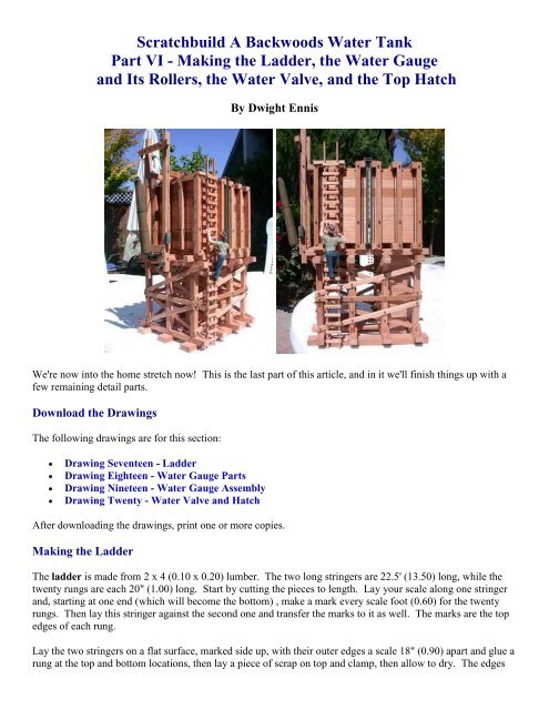
Scratchbuild A Backwoods Water Tank Part VI - Making the Ladder ...
Scratchbuild A Backwoods Water Tank Part VI - Making the Ladder ...
Scratchbuild A Backwoods Water Tank Part VI - Making the Ladder ...
- No tags were found...

Create successful ePaper yourself
Turn your PDF publications into a flip-book with our unique Google optimized e-Paper software.
<strong>Scratchbuild</strong> A <strong>Backwoods</strong> <strong>Water</strong> <strong>Tank</strong><br />
<strong>Part</strong> <strong>VI</strong> - <strong>Making</strong> <strong>the</strong> <strong>Ladder</strong>, <strong>the</strong> <strong>Water</strong> Gauge<br />
and Its Rollers, <strong>the</strong> <strong>Water</strong> Valve, and <strong>the</strong> Top Hatch<br />
By Dwight Ennis<br />
We're now into <strong>the</strong> home stretch now! This is <strong>the</strong> last part of this article, and in it we'll finish things up with a<br />
few remaining detail parts.<br />
Download <strong>the</strong> Drawings<br />
The following drawings are for this section:<br />
<br />
<br />
<br />
<br />
Drawing Seventeen - <strong>Ladder</strong><br />
Drawing Eighteen - <strong>Water</strong> Gauge <strong>Part</strong>s<br />
Drawing Nineteen - <strong>Water</strong> Gauge Assembly<br />
Drawing Twenty - <strong>Water</strong> Valve and Hatch<br />
After downloading <strong>the</strong> drawings, print one or more copies.<br />
<strong>Making</strong> <strong>the</strong> <strong>Ladder</strong><br />
The ladder is made from 2 x 4 (0.10 x 0.20) lumber. The two long stringers are 22.5' (13.50) long, while <strong>the</strong><br />
twenty rungs are each 20" (1.00) long. Start by cutting <strong>the</strong> pieces to length. Lay your scale along one stringer<br />
and, starting at one end (which will become <strong>the</strong> bottom) , make a mark every scale foot (0.60) for <strong>the</strong> twenty<br />
rungs. Then lay this stringer against <strong>the</strong> second one and transfer <strong>the</strong> marks to it as well. The marks are <strong>the</strong> top<br />
edges of each rung.<br />
Lay <strong>the</strong> two stringers on a flat surface, marked side up, with <strong>the</strong>ir outer edges a scale 18" (0.90) apart and glue a<br />
rung at <strong>the</strong> top and bottom locations, <strong>the</strong>n lay a piece of scrap on top and clamp, <strong>the</strong>n allow to dry. The edges
of each rung will extend a scale inch (0.50) beyond <strong>the</strong> outside edge of each stringer. Also, remember, <strong>the</strong> top<br />
rung is 1.50" from <strong>the</strong> top ends of <strong>the</strong> stringers.<br />
Glue two more rungs in place roughly equidistant between <strong>the</strong> top and bottom rungs, clamp and allow to dry.
The four rungs act to maintain <strong>the</strong> ladder's shape. Go ahead now and glue on <strong>the</strong> remaining rungs, <strong>the</strong>n clamp<br />
<strong>the</strong> whole assembly and allow to dry. Once everything sets up, emboss nail heads on <strong>the</strong> rungs, two per rung<br />
per side.<br />
The ladder is now complete. We'll mount it later.
<strong>Making</strong> <strong>the</strong> <strong>Water</strong> Gauge<br />
Refer to Drawing Eighteen for <strong>the</strong> piece parts of <strong>the</strong> <strong>Water</strong> Gauge. Basically, it consists of two side channels,<br />
<strong>the</strong> scale, and <strong>the</strong> indicator. The side channels are fabricated from Evergreen Scale Models styrene, as is <strong>the</strong><br />
Indicator (you'll need to glue two pieces toge<strong>the</strong>r to get <strong>the</strong> proper thickness for <strong>the</strong> Indicator). The scale is<br />
made of a piece of basswood.<br />
None of <strong>the</strong>se materials is particularly critical. You can really use whatever will work. When I was ready to<br />
make mine, I knew what I had in mind, <strong>the</strong>n went to <strong>the</strong> hobby shop and looked over <strong>the</strong> styrene in stock. I<br />
simply picked out what looked right. <strong>Part</strong> of scratchbuilding is being able to visualize what you need, <strong>the</strong>n find<br />
appropriate materials to make it from.<br />
You'll notice in <strong>the</strong> photo below that my side channels don't have <strong>the</strong> two holes in each end. This is because I<br />
added <strong>the</strong>m afterward. Once I had <strong>the</strong> gauge assembled, I realized that it would look better (to my eye) if <strong>the</strong>re<br />
was a visible means of holding it toge<strong>the</strong>r. Consequently, I added <strong>the</strong> NBW's and short sections of 0.030<br />
diameter brass wire shown in Drawing Nineteen.<br />
The scale was painted white. I <strong>the</strong>n hand-painted <strong>the</strong> scale lines in black so I'd have a more rustic look. My<br />
hand isn't steady enough to paint <strong>the</strong> numbers as well, so I used some dry transfers I had laying around. You<br />
could certainly hand paint yours, or you can cut out <strong>the</strong> scale from <strong>the</strong> drawing and laminate it to a piece of<br />
wood.<br />
The eyelet in <strong>the</strong> top of <strong>the</strong> indicator is from Micro-Mark (#60405). These are similar, if not identical, to <strong>the</strong><br />
ones supplied in some Hartford Products kits. After losing several while assembling his kits, I laid a<br />
supply. You could just as easily make one from brass wire.<br />
The side channels and indicator are painted Grimy Black, with a dusting of Rust.<br />
The scale is glued to one side channel, with it's back edge pressed against <strong>the</strong> inside of <strong>the</strong> channel flange, and<br />
centered lengthwise. The indicator is <strong>the</strong>n glued to <strong>the</strong> scale. Affix a length of pre-blackened chain to <strong>the</strong><br />
eyelet before attaching <strong>the</strong> indicator.<br />
Where you put <strong>the</strong> indicator depends on how full you want your tank to be. The lower it is, <strong>the</strong> fuller <strong>the</strong> tank<br />
is. On <strong>the</strong> real ones, <strong>the</strong> chain attached to <strong>the</strong> indicator was attached to a float inside <strong>the</strong> tank. As <strong>the</strong> tank got<br />
fuller, <strong>the</strong> float would rise, lowering <strong>the</strong> indicator on <strong>the</strong> scale.
Glue on <strong>the</strong> o<strong>the</strong>r side channel. At this point, I slid <strong>the</strong> 0.030 wire through <strong>the</strong> holes and glued on <strong>the</strong> NBW<br />
castings. These were smaller castings I had left over from a Hartford kit. Any small NBW castings will do.<br />
Cut a piece of wood 0.10 x 0.10 x 4.80 to make <strong>the</strong> backing board, and glue it to <strong>the</strong> rear of <strong>the</strong> scale between<br />
<strong>the</strong> channel flanges. This completes <strong>the</strong> <strong>Water</strong> Gauge.<br />
<strong>Making</strong> <strong>the</strong> <strong>Water</strong> Gauge Rollers<br />
These rollers guide <strong>the</strong> <strong>Water</strong> Gauge Indicator chain at <strong>the</strong> top of <strong>the</strong> tank, and allow <strong>the</strong> chain to easily slide<br />
up and down. I thought of using small pulleys here, but couldn't find any that I liked. The support brackets for<br />
<strong>the</strong> <strong>Water</strong> Gauge Rollers are made from 1/4" x 1/4" Styrene Angle. Refer to Drawing Eighteen for<br />
dimensions. Again, <strong>the</strong>se are painted Grimy Black with a dusting of Rust. The rollers <strong>the</strong>mselves are a piece of<br />
1/16" diameter brass rod, cut 0.40" long. This allows <strong>the</strong> brackets to fit <strong>the</strong> <strong>Tank</strong> Supports. Paint or blacken<br />
<strong>the</strong> brass rods.
(Apologies for <strong>the</strong> poor quality of this photo)<br />
Here's <strong>the</strong> completed rollers. The NBW's I used here were <strong>the</strong> same ones I used on <strong>the</strong> gauge itself. Here you<br />
can see <strong>the</strong> 0.030 wire "bolts" extending between <strong>the</strong> channels. Glue <strong>the</strong> gauge to <strong>the</strong> tank centered on one side<br />
(which side is entirely up to you... it depends on which side will be more visible on your layout). Drill a 1/16"<br />
or so hole in <strong>the</strong> tank top where <strong>the</strong> chain enters <strong>the</strong> tank, and glue <strong>the</strong> chain into <strong>the</strong> hole.
The <strong>Water</strong> Valve<br />
The <strong>Water</strong> Valve is a simple lever with a ling chain that allowed <strong>the</strong> engine crew to open and close <strong>the</strong> water<br />
valve. Pull <strong>the</strong> chain and water flows. Let go and it stops.<br />
The brackets are made from <strong>the</strong> same 1/4 x 1/4 Styrene Angle previously used to make <strong>the</strong> roller brackets. The<br />
only difference is that <strong>the</strong>y're a little longer and have two holes on <strong>the</strong> bottom side instead of one. Refer to<br />
Drawing Twenty for dimensions.<br />
The lever is made from 0.080 x 0.156 Styrene. Again, refer to Drawing Twenty for dimensions. Assemble as<br />
shown in <strong>the</strong> photo below, paint with Grimy Black and Rust, add a length of chain to each end and mount it to<br />
<strong>the</strong> tank with <strong>the</strong> long end sticking out <strong>the</strong> front. Drill a hole in <strong>the</strong> tank for <strong>the</strong> chain on <strong>the</strong> short end to enter<br />
<strong>the</strong> tank (just like <strong>the</strong> water gauge chain). The chain from <strong>the</strong> long end should hang down far enough to allow it<br />
to be reached by <strong>the</strong> engine crew while standing on <strong>the</strong> locomotive tender.
<strong>Making</strong> <strong>the</strong> Hatch<br />
The hatch in <strong>the</strong> top provides access to <strong>the</strong> inside of <strong>the</strong> tank for service. Consequently, it should be mounted<br />
near a tank wall to allow for a ladder down inside <strong>the</strong> tank. The hatch itself is simple, being nothing more than<br />
a hinged cover over a frame of 2 x 4's (0.10 x 0.20). Again, refer to Drawing Twenty for dimensions. The<br />
Materials List in <strong>Part</strong> I will provide <strong>the</strong> lumber sizes used. The hinges are <strong>the</strong> same ones used on <strong>the</strong> Frost<br />
Box Door with <strong>the</strong> long end cut down, and are attached <strong>the</strong> same way. The handle is <strong>the</strong> same O-Scale<br />
Grabiron used on <strong>the</strong> Frost Box Door as well (it came as a set of two). Don't forget to emboss <strong>the</strong> nail heads on<br />
<strong>the</strong> Hatch Cover Braces.
Attaching <strong>the</strong> <strong>Ladder</strong><br />
Decide where you want your ladder attached and glue a couple of lengths of 2 x 4 (0.10 x 0.20) to <strong>the</strong> <strong>Tank</strong><br />
Supports, one at <strong>the</strong> top and one at <strong>the</strong> bottom. Emboss nail heads and glue <strong>the</strong> ladder to <strong>the</strong>se 2 x 4's. Note<br />
that <strong>the</strong> ladder stringers are "toe-nailed" at <strong>the</strong> sides into <strong>the</strong> 2 x 4's. The bottom of <strong>the</strong> left stringer on mine<br />
glues to <strong>the</strong> bottom sill of <strong>the</strong> front bent. Depending upon where you decide to mount your ladder, your mileage<br />
may vary.
The figure on my ladder is from Just Plain Folk which I picked up at last year's Queen Mary Show.<br />
A Quick Word About Wea<strong>the</strong>ring<br />
As you've undoubtedly noticed by now, no attempt has been made to wea<strong>the</strong>r <strong>the</strong> wood. This was a deliberate<br />
choice on my part. Redwood will wea<strong>the</strong>r quite a bit in a single year when out of doors. The Sanding Facility<br />
I built last fall wea<strong>the</strong>red substantially after a single winter. The Sanding Facility is visible in <strong>the</strong> finished<br />
photos at <strong>the</strong> end of this article, just to <strong>the</strong> right of <strong>the</strong> <strong>Water</strong> <strong>Tank</strong>. When it was installed, its finish was very<br />
much <strong>the</strong> same as <strong>the</strong> tank's. For that reason, I chose to let <strong>the</strong> wood wea<strong>the</strong>r naturally.<br />
Mounting in <strong>the</strong> Garden<br />
If you live in an area with occasional high winds, you may want to consider some method of holding <strong>the</strong> tank<br />
upright and in place. It's a top-heavy model, and <strong>the</strong> flat surfaces of <strong>the</strong> tank proper will offer resistance to <strong>the</strong><br />
wind. As I write this, we had wind gusts up to 30 or 40 mph last night, and this morning <strong>the</strong> tank was laying on
its side. Nothing at all was broken - ei<strong>the</strong>r a testament to how sturdily it was constructed or (more likely) sheer<br />
luck!<br />
Drilling four 1/8" holes in <strong>the</strong> bottom and inserting some 1/8" diameter brass rods that will push into <strong>the</strong> ground<br />
and hold <strong>the</strong> tank upright is one solution. Screwing <strong>the</strong> foundation beams (from <strong>the</strong> underside) to a piece of<br />
pressure treated plywood or o<strong>the</strong>r material that will sit in <strong>the</strong> ground abd be covered by dirt is ano<strong>the</strong>r.<br />
Conclusion<br />
Your <strong>Backwoods</strong> <strong>Water</strong> <strong>Tank</strong> is now finished and ready to start quenching <strong>the</strong> never-ending thirst of those<br />
iron horses. Thanks to your perseverance, you now have a totally unique structure for your garden<br />
railroad. Even if you followed <strong>the</strong> plans and instructions of this article to <strong>the</strong> letter, it's highly doubtful that<br />
your tank is exactly like mine or anyone else's. So sit back, have a beer, and admire your handiwork!! You<br />
deserve it!!<br />
I hope you've had as much fun building this project as I did, and I sincerely hope that <strong>the</strong> insights, techniques,<br />
and skills picked up along <strong>the</strong> way will give you <strong>the</strong> confidence to design and scratchbuild o<strong>the</strong>r projects. One<br />
big advantage of scratchbuilding is that you're not limited to only those structures commercially produced, with<br />
all <strong>the</strong>ir inherent scale issues and "European Ancestry" look. <strong>Scratchbuild</strong>ing allows you to produce anything<br />
for any era to fit in any space, so you have total freedom. While this structure is a rustic design made of wood,<br />
<strong>the</strong>re's no reason why it couldn't just have easily been a large round water tank for a more modern<br />
railroad. Stations and industrial buildings can be produced - anything you can imagine can be scratchbuilt with<br />
a little imagination.<br />
If you have any questions about this article, <strong>the</strong> water tank, or anything else, please feel free to email me (my<br />
email address is in my Profile) or post your question on <strong>the</strong> myLargescale.com forums and I'll do my best to<br />
answer <strong>the</strong>m.<br />
I'll wrap things up with some photos of <strong>the</strong> finished model.
Finished Photos<br />
Here are some photos of <strong>the</strong> finished tank installed on <strong>the</strong> layout...<br />
SCLCo No. 1 takes on water before heading out for her next run. Note <strong>the</strong> natural wea<strong>the</strong>ring of<br />
<strong>the</strong> Sanding Facility in <strong>the</strong> foreground. Look carefully and you can also see <strong>the</strong> "patch" on <strong>the</strong><br />
end of <strong>the</strong> water spout made necessary by my own carelessness.
Steam locomotives are thirsty beasts, to be sure.
Again, note <strong>the</strong> difference in <strong>the</strong> finish between <strong>the</strong> newly installed <strong>Water</strong> <strong>Tank</strong> and <strong>the</strong> Sanding<br />
Facility, which has one winter outside under its belt. Also, note how much better <strong>the</strong> spout looks<br />
with <strong>the</strong> business end hogged out.
Detail Photos<br />
These photos were taken immediately upon completion and prior to installation. They show some of <strong>the</strong> details<br />
more clearly, as well as <strong>the</strong> overall model.
Compare <strong>the</strong> business end of <strong>the</strong> spout here (prior to hogging out) with <strong>the</strong><br />
photo on <strong>the</strong> previous pages. Quite a difference a little effort makes. The<br />
figure climbing <strong>the</strong> ladder is from ''Just Plain Folk'' - unfortunately, I didn't<br />
to save <strong>the</strong> part number.
A relative close-up of <strong>the</strong> right side...
and of <strong>the</strong> front...
and of <strong>the</strong> left side. I made a sign for mine with a spare 2 x 10 and dry<br />
transfers from Woodland Scenics.
A close-up of <strong>the</strong> Frost Box Door...
and a couple of views of <strong>the</strong> top to wrap things up.
That's all I have. I'll be looking forward to photos of your finished <strong>Backwoods</strong> <strong>Water</strong> <strong>Tank</strong>s on <strong>the</strong> forums, as<br />
well as some shots of your o<strong>the</strong>r creations. See you <strong>the</strong>re.