The M14 Conversion to The M1 Garand - Ontario Airsoft WWII Re ...
The M14 Conversion to The M1 Garand - Ontario Airsoft WWII Re ...
The M14 Conversion to The M1 Garand - Ontario Airsoft WWII Re ...

Create successful ePaper yourself
Turn your PDF publications into a flip-book with our unique Google optimized e-Paper software.
<strong>The</strong> <strong><strong>M1</strong>4</strong> <strong>Conversion</strong> <strong>to</strong> <strong>The</strong> <strong>M1</strong> <strong>Garand</strong><br />
Version One<br />
Project Completed and Written<br />
By<br />
Lee Cassar<br />
Feb. 19, 2007
Table of Contents<br />
Introduction:........................................................................................................................ 3<br />
Tools needed for the <strong>Conversion</strong>:....................................................................................... 4<br />
Disassembly:....................................................................................................................... 5<br />
Modifications:..................................................................................................................... 7<br />
Assembly: ......................................................................................................................... 10<br />
2
Introduction:<br />
<strong>The</strong> <strong><strong>M1</strong>4</strong> is a rifle that I wanted <strong>to</strong> acquire from the<br />
first time that I saw it and once I learned that it<br />
could be converted <strong>to</strong> the <strong>M1</strong> <strong>Garand</strong> then I knew I<br />
would be investing in one. As is, the <strong><strong>M1</strong>4</strong> does not<br />
look <strong>to</strong>o out of place on the <strong>WWII</strong> airsoft field, sort<br />
of a larger version of the <strong>M1</strong> Carbine. But still it<br />
was not a weapon that was available during World<br />
War Two.<br />
<strong>The</strong>refore, I set out <strong>to</strong> modify my TM <strong><strong>M1</strong>4</strong> <strong>to</strong> a <strong>M1</strong><br />
<strong>Garand</strong>. Will the end result of this modification give you an exact replica of a real <strong>M1</strong><br />
<strong>Garand</strong>? No, no it will not. If you want an exact replica of a <strong>M1</strong> <strong>Garand</strong> rifle then I<br />
would suggest purchasing the Marushin <strong>M1</strong> <strong>Garand</strong> rifle. I have had the pleasure of<br />
seeing a Marushin rifle up close and it is truly a beautiful weapon. However, if you are<br />
looking for an alternative <strong>to</strong> the Marushin gas powered rifle then this may be a project for<br />
you <strong>to</strong> consider. This version of the modification will bring your <strong><strong>M1</strong>4</strong> very close <strong>to</strong><br />
looking and feeling like a <strong>M1</strong> <strong>Garand</strong>.<br />
You can also choose <strong>to</strong> go beyond this project and make your version look even more<br />
authentic by modifying the s<strong>to</strong>ck, changing the butt plate, cutting off the au<strong>to</strong>/semi firing<br />
switch, etc. However, this version of the modification will step you through easily<br />
modifying your TM <strong><strong>M1</strong>4</strong> within a few hours.<br />
<strong>The</strong> project cost me approx. $150cdn and I know that it could have been done for less<br />
because I purchased items that I did not use for this version, such as a <strong>M1</strong> <strong>Garand</strong> wood<br />
s<strong>to</strong>ck, butt plate and screws. <strong>The</strong> unused items will be used in a later version <strong>to</strong> achieve a<br />
full wood and metal rifle. I was also lucky enough <strong>to</strong> pick up a plastic <strong><strong>M1</strong>4</strong> faux wood<br />
s<strong>to</strong>ck on E-bay for $25 USD. I purchased this item for two reasons, one, if I screwed up<br />
the project I would have a back up, and second, if I want <strong>to</strong> switch the rifle back <strong>to</strong> a <strong><strong>M1</strong>4</strong><br />
I can easily do that.<br />
I should note at this point that this conversion will require you <strong>to</strong> shorten your existing<br />
<strong><strong>M1</strong>4</strong> plastic s<strong>to</strong>ck, so if you are not willing <strong>to</strong> do that then you may not want <strong>to</strong> go any<br />
further or consider buying a back up TM <strong><strong>M1</strong>4</strong> s<strong>to</strong>ck.<br />
<strong>The</strong>re are several sources <strong>to</strong> obtain the <strong>Garand</strong> parts that are needed for this project. I<br />
purchased my parts from two sources, E-bay and Numrich Gun Parts Corporation. I got<br />
the Gas Cylinder, the Frontguard, <strong>Re</strong>arguard and the s<strong>to</strong>ck from E-bay at a great price<br />
and everything else was purchased from Numrich Gun Parts. <strong>The</strong> above-mentioned<br />
items are also available from Numrich; I just purchased them from e-bay because I got<br />
them at the right price. I really like Numrich Gun Parts because they have everything at<br />
very good prices and the website (http://www.e-gunparts.com/) actually shows what is in<br />
and out of s<strong>to</strong>ck. I tried ordering from the website but for some reason it wouldn’t work<br />
3
for me so instead I just called them up and placed the order. I will include them on our<br />
vendor page of the <strong>Ontario</strong> <strong>Airsoft</strong> <strong>WWII</strong> <strong>Re</strong>-enac<strong>to</strong>rs’ website.<br />
I should point out that this is my first modification and I do not profess <strong>to</strong> be a gunsmith<br />
nor an expert in anyway. <strong>The</strong>re is an existing conversion kit out there that you can<br />
purchase for $350USD (look on the Weapons section of the website), that I’m sure has<br />
been done much better then my modification. I’m also sure that there could have been<br />
better ways that I could have done certain things but hopefully I have made all the<br />
mistakes for you and if you do find better ways <strong>to</strong> modify this project please share it so I<br />
can include it with these instructions.<br />
Tools needed for the <strong>Conversion</strong>:<br />
Scroll saw or hacksaw<br />
1.5 Allen key<br />
2.5 Allen key<br />
Dremel Tool and cutting disks<br />
Rubber mallet<br />
Flat Head Screwdriver<br />
Electrical tape<br />
Thick Gel Super Glue<br />
Measuring tape<br />
Items Needed for <strong>Conversion</strong>:<br />
<strong><strong>M1</strong>4</strong> rifle<br />
Plastic <strong><strong>M1</strong>4</strong> s<strong>to</strong>ck<br />
Gas Cylinder and plug<br />
Front site and screw<br />
Front handguard<br />
<strong>Re</strong>ar handguard<br />
<strong>Re</strong>ar handguard clip<br />
Handguard liner<br />
Handguard Ferrule<br />
Lower Band<br />
Black Electrical tape<br />
Wood Dowel (7 <strong>to</strong> 9½ inches in length and<br />
3/8” thick)<br />
Stain (Walnut)<br />
4
Disassembly:<br />
1. Basically, follow the manual <strong>to</strong> field strip the weapon. If you do not have a manual<br />
then following these steps.<br />
• Pull the trigger guard (you may need <strong>to</strong> use the loading rod <strong>to</strong> do this) and pull<br />
out the trigger housing<br />
.<br />
• Slightly separate the receiver assembly from the s<strong>to</strong>ck. Open the buttplate and<br />
pull out the battery connec<strong>to</strong>r and fuse. If you do not do this part then you<br />
will not be able <strong>to</strong> pull the receiver assemble out any further.<br />
• Gently pull away the barrel and receiver assembly from the s<strong>to</strong>ck and<br />
disconnect the connec<strong>to</strong>r.<br />
5
2. Use the 1.5 Allen key <strong>to</strong> unscrew the Flash Suppressor Set Screw.<br />
3. Once the Flash suppressor set screw is far enough back (you do not need <strong>to</strong> remove it)<br />
you can then unscrew the Flash suppressor nut off and remove the Flash suppressor<br />
from the barrel.<br />
4. Next, remove the Gas Cylinder assembly by using the 1.5 Allen key <strong>to</strong> unscrew the Gas<br />
Cylinder assembly screw. Once the assembly is free remove it from the barrel.<br />
6
5. Using a screwdriver gently remove the Hand Guard <strong>Re</strong>ar Band so that you will be able <strong>to</strong><br />
remove the Hand Guard.<br />
6. Using a 2.5 Allen Key remove the Front swivel. Also remove the steel re-enforcement<br />
off the s<strong>to</strong>ck.<br />
<strong>The</strong>re… you have completed the disassembly. Take all the <strong><strong>M1</strong>4</strong> parts and put them away.<br />
At this point you may want <strong>to</strong> take a break maybe even a drink <strong>to</strong> steady the nerves because<br />
the hard part comes next.<br />
Modifications:<br />
I should note that at this point you may what <strong>to</strong> go a different way, such as getting a longer<br />
outer barrel. Longer outer barrel means less cuts. However, what I did and documented is as<br />
follows.<br />
7
7. Mark off 5/8 of an inch from the back of the <strong>Re</strong>ar hand guard <strong>to</strong> the clip. Sorry guys, but<br />
for you metric boys, you will need <strong>to</strong> do the conversion. Cut this section off.<br />
8. Using a Dremel you will now need <strong>to</strong> extend the grove on the outer barrel so the <strong>Re</strong>ar<br />
hand guard clip will be able <strong>to</strong> catch. You will need <strong>to</strong> extend it approx. ¼ of an inch.<br />
Note: the rifle is upside down <strong>to</strong> give you a better angle.<br />
9. Now that you have cut down the rear hand guard you will also need <strong>to</strong> adjust the section<br />
of the rear hand guard that meets the s<strong>to</strong>ck so that the bolt slide will fit. I used the<br />
Dremel <strong>to</strong> make the cuts. Take your time with these cuts. Cut across 5/8 and then cut at<br />
an angle the same length. Better <strong>to</strong> make small cuts and check the fit.<br />
8
10. Mark off 3 ¾ inches from the front end of the plastic s<strong>to</strong>ck. This should be just at the one<br />
end of the swing swivel. Note: I used black electrical tape <strong>to</strong> mark off the cut off line.<br />
Make the cut.<br />
11. You will now need <strong>to</strong> trim the inside of the s<strong>to</strong>ck, at the new cut, so that it will fit around<br />
the Lower Band of the Handguard. I used the Dremel for this part and worked slowly<br />
checking the fit and making any additional trimming as needed. <strong>The</strong> plastic almost melts<br />
as you are making these small cuts so be very careful.<br />
Okay, that’s it for cutting. Now let’s move on <strong>to</strong> the assembly.<br />
12. Again, using the Dremel, cut the inner and <strong>to</strong>p of the S<strong>to</strong>ck Ferrule Assembly. <strong>The</strong> more<br />
of the back edge that you can leave the better but you will not be able <strong>to</strong> leave much<br />
seeing that you will need <strong>to</strong> pull apart the assembly so that it will fit on<strong>to</strong> the s<strong>to</strong>ck. I cut<br />
<strong>to</strong>o much of mine off, I should have left more of an edge. Now put this aside until it is<br />
time <strong>to</strong> add it <strong>to</strong> the s<strong>to</strong>ck.<br />
9
Assembly:<br />
13. My front handguard did not come with the metal<br />
hardware so let’s just assume yours did not either and<br />
assembly the front handguard first.<br />
• Attach the Handguard Ferrule <strong>to</strong> the front of the Handguard and the Lower Band<br />
<strong>to</strong> the back of the Handguard. <strong>The</strong> Handguard Liner is then pushed in<strong>to</strong> place<br />
from the bot<strong>to</strong>m of the handguard <strong>to</strong> help hold the Ferrule and lower band in<br />
place.<br />
14. My Gas Cylinder was already assembled with the Front sight, Gas Cylinder lock and<br />
plug, and the S<strong>to</strong>ck Swivel.<br />
• However, we do need <strong>to</strong> add the dowel <strong>to</strong> the cylinder. I used a 7-inch dowel that<br />
was 3/8 inches thick. I used black electrical tape <strong>to</strong> cover the dowel and <strong>to</strong> give<br />
me the thickness, that when inserted in<strong>to</strong> the Gas Cylinder, that it would stay in<br />
place. First, run a strip of tape vertically from one end <strong>to</strong> the other and then back<br />
10
<strong>to</strong> the start. <strong>The</strong>n wrap the tape around the dowel horizontally, covering the entire<br />
length of the dowel.<br />
• Once you have finished taping the dowel insert it in<strong>to</strong> the Gas Cylinder making<br />
sure that the dowel protrudes 5 3/8 inches from the Gas Cylinder. <strong>The</strong> end of the<br />
dowel has <strong>to</strong> meet the operating rod.<br />
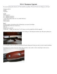
15. Okay, everything has been cut and modified, so we are now ready <strong>to</strong> re-assemble the<br />
rifle.<br />
• Clip the <strong>Re</strong>ar handguard <strong>to</strong> the barrel.<br />
• Now slide the Front handguard over the barrel and fit the rear handguard in<strong>to</strong> the<br />
Lower Band.<br />
• Slip the Gas Cylinder assembly, including the modified dowel, over the outer<br />
barrel. Make sure that the groves of the outer barrel line up with the teeth of the<br />
Gas Cylinder. Note that the teeth of the <strong>M1</strong> Gas Cylinder are thicker then the<br />
Teeth of the <strong><strong>M1</strong>4</strong> Flash suppressor, which means one of two things. One, you<br />
could modify the outer barrel by grinding down the groves, or two, take a rubber<br />
mallet and force the teeth of the Gas Cylinder <strong>to</strong> fit in<strong>to</strong> the grooves. I chose <strong>to</strong><br />
do the latter. Again, keeping in mind that if I ever want <strong>to</strong> change the rifle back <strong>to</strong><br />
a <strong><strong>M1</strong>4</strong> I can do so. You will need <strong>to</strong> hammer the Gas Cylinder until the back is<br />
connected <strong>to</strong> Handguard Ferrule (see the above picture), this will only take a few<br />
hits. With the teeth of the Gas Cylinder biting in<strong>to</strong> the outer barrel grooves the<br />
Gas Cylinder is secured.<br />
11
(I should note that if you do decide <strong>to</strong> grind the front of the outer barrel that the<br />
barrel is slightly short and you would have <strong>to</strong> adjust your cuts accordingly.<br />
However, this would allow you <strong>to</strong> secure the Gas Cylinder <strong>to</strong> the outer barrel by<br />
using the Gas Cylinder Lock.)<br />
• <strong>The</strong> following picture shows the assembly without the s<strong>to</strong>ck and before the Front<br />
Handguard’s colour was adjusted.<br />
16. Now that you know that everything fits properly, you may need <strong>to</strong> adjust that colour of<br />
the Handguard parts. If you don’t need <strong>to</strong> then move <strong>to</strong> step 16 for final assembly.<br />
Otherwise use your stain <strong>to</strong> adjust the colour. I used a walnut stain. Plus, <strong>to</strong> save time I<br />
did not strip the parts, instead I put light coats, allowing them <strong>to</strong> dry between applications<br />
without wiping off the stain, until I had the desired colour.<br />
17. Use the Thick Gel Super Glue <strong>to</strong> attach the cut S<strong>to</strong>ck Ferrule Assembly <strong>to</strong> the front of the<br />
s<strong>to</strong>ck.<br />
18. <strong>The</strong> final part of the assembly is <strong>to</strong> re-connect the s<strong>to</strong>ck. Follow the disassembly steps in<br />
reverse order. Once the s<strong>to</strong>ck is in place you will need <strong>to</strong> take a strip of black electrical<br />
tape, cut it in half (length wise) and wrap it around the front of the s<strong>to</strong>ck and the <strong>Re</strong>ar<br />
12
Handguard <strong>to</strong> secure the s<strong>to</strong>ck in place (still working on a better method <strong>to</strong> secure the<br />
front of the s<strong>to</strong>ck).<br />
Your assembly is complete and your AEG <strong>M1</strong> <strong>Garand</strong> is ready <strong>to</strong> take the field.<br />
<strong>The</strong> next step is <strong>to</strong> modify the <strong><strong>M1</strong>4</strong> Mags so that it does not protrude out of the bot<strong>to</strong>m as far<br />
as they do on the <strong><strong>M1</strong>4</strong>, but that’s for another project.<br />
13