1 Programming PIC Microcontrollers in PicBasic Pro – Lesson 1 ...
1 Programming PIC Microcontrollers in PicBasic Pro – Lesson 1 ...
1 Programming PIC Microcontrollers in PicBasic Pro – Lesson 1 ...

Create successful ePaper yourself
Turn your PDF publications into a flip-book with our unique Google optimized e-Paper software.
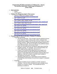
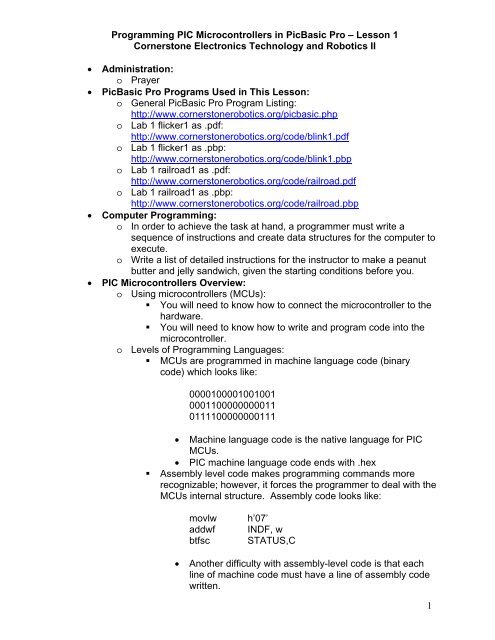
<strong><strong>Pro</strong>gramm<strong>in</strong>g</strong> <strong>PIC</strong> <strong>Microcontrollers</strong> <strong>in</strong> <strong>PicBasic</strong> <strong>Pro</strong> – <strong>Lesson</strong> 1<br />
Cornerstone Electronics Technology and Robotics II<br />
� Adm<strong>in</strong>istration:<br />
o Prayer<br />
� <strong>PicBasic</strong> <strong>Pro</strong> <strong>Pro</strong>grams Used <strong>in</strong> This <strong>Lesson</strong>:<br />
o General <strong>PicBasic</strong> <strong>Pro</strong> <strong>Pro</strong>gram List<strong>in</strong>g:<br />
http://www.cornerstonerobotics.org/picbasic.php<br />
o Lab 1 flicker1 as .pdf:<br />
http://www.cornerstonerobotics.org/code/bl<strong>in</strong>k1.pdf<br />
o Lab 1 flicker1 as .pbp:<br />
http://www.cornerstonerobotics.org/code/bl<strong>in</strong>k1.pbp<br />
o Lab 1 railroad1 as .pdf:<br />
http://www.cornerstonerobotics.org/code/railroad.pdf<br />
o Lab 1 railroad1 as .pbp:<br />
http://www.cornerstonerobotics.org/code/railroad.pbp<br />
� Computer <strong><strong>Pro</strong>gramm<strong>in</strong>g</strong>:<br />
o In order to achieve the task at hand, a programmer must write a<br />
sequence of <strong>in</strong>structions and create data structures for the computer to<br />
execute.<br />
o Write a list of detailed <strong>in</strong>structions for the <strong>in</strong>structor to make a peanut<br />
butter and jelly sandwich, given the start<strong>in</strong>g conditions before you.<br />
� <strong>PIC</strong> <strong>Microcontrollers</strong> Overview:<br />
o Us<strong>in</strong>g microcontrollers (MCUs):<br />
� You will need to know how to connect the microcontroller to the<br />
hardware.<br />
� You will need to know how to write and program code <strong>in</strong>to the<br />
microcontroller.<br />
o Levels of <strong><strong>Pro</strong>gramm<strong>in</strong>g</strong> Languages:<br />
� MCUs are programmed <strong>in</strong> mach<strong>in</strong>e language code (b<strong>in</strong>ary<br />
code) which looks like:<br />
0000100001001001<br />
0001100000000011<br />
0111100000000111<br />
� Mach<strong>in</strong>e language code is the native language for <strong>PIC</strong><br />
MCUs.<br />
� <strong>PIC</strong> mach<strong>in</strong>e language code ends with .hex<br />
� Assembly level code makes programm<strong>in</strong>g commands more<br />
recognizable; however, it forces the programmer to deal with the<br />
MCUs <strong>in</strong>ternal structure. Assembly code looks like:<br />
movlw h’07’<br />
addwf INDF, w<br />
btfsc STATUS,C<br />
� Another difficulty with assembly-level code is that each<br />
l<strong>in</strong>e of mach<strong>in</strong>e code must have a l<strong>in</strong>e of assembly code<br />
written.<br />
1
� Assembly code commands are executed at the crystal<br />
frequency/4.<br />
� <strong>PIC</strong> assembly code ends with .asm<br />
� High-level language: A programmer needs a programm<strong>in</strong>g<br />
language that relates to problem solv<strong>in</strong>g more than the <strong>in</strong>ternal<br />
structure of a microcontroller.<br />
� The most common high-level language for programm<strong>in</strong>g<br />
MCUs is C.<br />
� We will start with the language <strong>PicBasic</strong> <strong>Pro</strong>, then <strong>in</strong> time,<br />
move on to C. <strong>PicBasic</strong> <strong>Pro</strong> code appears like:<br />
For c0 = 1 TO 100 ‘ Count from 1 to 100<br />
SOUND 1, [75,100] ‘ Generate tone on p<strong>in</strong> 1<br />
Pause 20 ‘ Delay 20 milliseconds<br />
Next ‘ Return to FOR and add 1 to c0<br />
� <strong>PicBasic</strong> <strong>Pro</strong> code ends with the extension .pbp.<br />
o <strong><strong>Pro</strong>gramm<strong>in</strong>g</strong> the microcontroller with <strong>PicBasic</strong> <strong>Pro</strong>:<br />
� You will need to communicate with the microcontroller and tell it<br />
what <strong>in</strong>structions you want it to perform. The program language<br />
for the <strong>PIC</strong> microcontrollers uses about 75 words, or<br />
<strong>in</strong>structions, called <strong>PicBasic</strong> <strong>Pro</strong> language. Make sure you<br />
program us<strong>in</strong>g commands that are handled by the <strong>PicBasic</strong> <strong>Pro</strong><br />
compiler (PBP), not the <strong>PicBasic</strong> Compiler. See:<br />
http://store.melabs.com/cat/PBP.html<br />
� You will program on the computer <strong>in</strong> <strong>PicBasic</strong> <strong>Pro</strong> language.<br />
You will then compile your program us<strong>in</strong>g the <strong>PicBasic</strong> <strong>Pro</strong><br />
compiler. The compiler first compiles the program <strong>in</strong>to<br />
assembly code (.asm) and then automatically converts the<br />
assembly code <strong>in</strong>to the f<strong>in</strong>al mach<strong>in</strong>e code (.hex) which is then<br />
programmed <strong>in</strong>to a microcontroller us<strong>in</strong>g the melabs U2<br />
programmer. See: http://melabs.com/products/usbprog.htm<br />
� Steps <strong>in</strong> programm<strong>in</strong>g a microcontroller will be discussed <strong>in</strong><br />
more detail later <strong>in</strong> the class.<br />
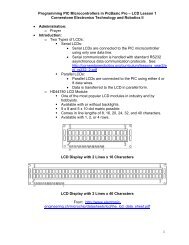
o <strong>PIC</strong>16F88:<br />
� Cost is about $2.60 each<br />
� The <strong>PIC</strong> 16F88 is an 18-p<strong>in</strong> device that is equipped with two<br />
<strong>in</strong>put/output ports, PORTA and PORTB.<br />
� PORTA has eight <strong>in</strong>put/output (I/O) l<strong>in</strong>es and the PORTB has<br />
eight I/O l<strong>in</strong>es available.<br />
� PORTA I/O l<strong>in</strong>es are labeled RA0, RA1, RA2, RA3, RA4,<br />
RA5, RA6, and RA7.<br />
� PORTB I/O l<strong>in</strong>es are labeled RB0, RB1, RB2, RB3, RB4,<br />
RB5, RB6, and RB7.<br />
� Order<strong>in</strong>g direct from Microchip:<br />
http://www.microchip.com/wwwproducts/Devices.aspx?dDocNa<br />
me=en010243<br />
� <strong>PIC</strong>16F88 datasheet:<br />
http://ww1.microchip.com/downloads/en/devicedoc/30487c.pdf<br />
2
� P<strong>in</strong> Layout:<br />
� <strong><strong>Pro</strong>gramm<strong>in</strong>g</strong> <strong>PIC</strong> <strong>Microcontrollers</strong>:<br />
o Outl<strong>in</strong>e of a <strong>PicBasic</strong> program:<br />
� <strong>PicBasic</strong> programs generally follow a predeterm<strong>in</strong>ed format <strong>in</strong><br />
the order given below.<br />
� Title<br />
� <strong>Pro</strong>gram description<br />
� Revision history<br />
� Constants/Def<strong>in</strong>es<br />
� Variables<br />
� Initialization<br />
� Ma<strong>in</strong> Code: Dur<strong>in</strong>g each ma<strong>in</strong> code cycle:<br />
o The MCU monitors the status of the <strong>in</strong>put sensors<br />
o Executes the logic programmed <strong>in</strong> the ma<strong>in</strong> code<br />
o Changes the state of the output devices<br />
o Input/Output Port Registers and Input/Output P<strong>in</strong>s:<br />
� In a computer, registers are a set of data storage places that are<br />
part of a computer processor. A register may hold a computer<br />
<strong>in</strong>struction, a storage address, or any k<strong>in</strong>d of data. In our<br />
immediate case, data stored <strong>in</strong> the I/O port register is 8-bit wide<br />
<strong>in</strong>formation about I/O p<strong>in</strong>s. See lesson addendum for the<br />
<strong>PIC</strong>16F88 Register File Map.<br />
� Ports are connected to <strong>in</strong>put/output (I/O) p<strong>in</strong>s <strong>in</strong> a <strong>PIC</strong>. PORTB<br />
is the I/O port name for the I/O p<strong>in</strong>s associated with PORTB.<br />
� Typically, an I/O port conta<strong>in</strong>s 8 p<strong>in</strong>s. For example, PORTB has<br />
8 p<strong>in</strong>s.<br />
3
� The <strong>PIC</strong>16F88 has two ports, PORTA and PORTB.<br />
� PORTA has 8 – I/O p<strong>in</strong>s (RA0 – RA7) and PORTB has 8 – I/O<br />
p<strong>in</strong>s (RB0 – RB7)<br />
� P<strong>in</strong>s can be accessed <strong>in</strong> a number of ways. One way to specify<br />
a p<strong>in</strong> is to use its PORT name and bit number:<br />
PORTB.1 = 1 ‘ Set PORTB, bit 1 to a 1 or HIGH (+5V)<br />
‘ PORTB.1 is p<strong>in</strong> RB1.<br />
PORTA.3 = 0 ‘ Set PORTA, bit 3 to a 0 or LOW (0V)<br />
‘ PORTA.3 is p<strong>in</strong> RA3.<br />
� Another way to access p<strong>in</strong>s is to change the entire I/O port<br />
register.<br />
PORTB = %00000000 ‘ Set all PORTB p<strong>in</strong>s to LOW<br />
PORTB = %11111111 ‘ Set all PORTB p<strong>in</strong>s to HIGH<br />
PORTA = %00000001 ‘ Set RA0 HIGH and RA1-RA7 to LOW.<br />
o Tri-State Registers (TRISx Registers):<br />
� TRISx as the data-direction register name for PORTx. For<br />
example, TRISB is the TRIS register for PORTB.<br />
� TRISx register is used to set up or <strong>in</strong>itialize a p<strong>in</strong> as an <strong>in</strong>put or<br />
an output. A “1” makes a p<strong>in</strong> an <strong>in</strong>put and a “0” makes a p<strong>in</strong> an<br />
output. To remember, 1 looks like the I <strong>in</strong> Input and the 0 looks<br />
like the O <strong>in</strong> Output. P<strong>in</strong>s can be arranged <strong>in</strong> any comb<strong>in</strong>ation<br />
of <strong>in</strong>put and output.<br />
� TRISB Register Order:<br />
In graphic form:<br />
As written <strong>in</strong> a program:<br />
4
� Example TRIS Registers:<br />
TRISB = %00001111 ‘ Set RB0 – RB3 as <strong>in</strong>puts and<br />
RB4 – RB7 as outputs.<br />
TRISA = %00000001 ‘ Set RA0 as an <strong>in</strong>put and RA1 –<br />
RA7 as outputs.<br />
� TRISx registers may be written <strong>in</strong> decimal form as well. TRISA<br />
= %00000000 can be written as TRISA = 0 and TRISB =<br />
%11111111 is the same as TRISB = 255.<br />
� Individual bit directions may also be set.<br />
TRISB.2 = 0 ‘Set p<strong>in</strong> PORTB.2 as an output.<br />
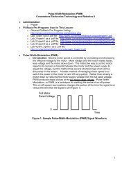
� New <strong>PicBasic</strong> <strong>Pro</strong> Commands:<br />
o PAUSE:<br />
Format:<br />
PAUSE Period<br />
Explanation:<br />
Pause the program for Period milliseconds. Period is 16-bits, so<br />
delays can be up to 65,535 milliseconds (a little over a m<strong>in</strong>ute).<br />
PAUSE has the same accuracy as the<br />
system clock. PAUSE assumes an oscillator frequency of<br />
4MHz. If an oscillator other that 4MHz is used, PBP must be told<br />
us<strong>in</strong>g a DEFINE OSC command. See the section on speed for<br />
more <strong>in</strong>formation.<br />
Example:<br />
PAUSE 1 ‘ Delay for 1 millisecond<br />
PAUSE 1000 ‘ Delay for 1000 milliseconds or 1<br />
second<br />
See page 112 <strong>in</strong> the melabs <strong>PicBasic</strong> <strong>Pro</strong> Compiler manual:<br />
http://melabs.com/resources/pbpmanual/<br />
o GOTO:<br />
Format:<br />
GOTO Label<br />
Explanation:<br />
<strong>Pro</strong>gram execution cont<strong>in</strong>ues with the statements at Label.<br />
Example:<br />
LED1: ‘ Label named LED1<br />
PORTB.0 = 1 ‘ Set p<strong>in</strong> RB0 to HIGH (+5V)<br />
GOTO LED1 ‘ <strong>Pro</strong>gram jumps to LED1<br />
See about page 146 <strong>in</strong> the <strong>PicBasic</strong> <strong>Pro</strong> Compiler manual:<br />
http://melabs.com/resources/pbpmanual/<br />
5
o END:<br />
Format:<br />
END<br />
Explanation:<br />
Stop program execution and enter low power mode. All of the<br />
I/O p<strong>in</strong>s rema<strong>in</strong> <strong>in</strong> their current state. END works by execut<strong>in</strong>g a<br />
Sleep <strong>in</strong>struction cont<strong>in</strong>uously <strong>in</strong> a loop.<br />
An END or STOP or GOTO should be placed at the end of<br />
every program to keep it from fall<strong>in</strong>g off the end of memory and<br />
start<strong>in</strong>g over.<br />
Example:<br />
END<br />
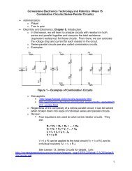
� Review of +5V Voltage Regulator Circuit:<br />
o The circuit below will create a +5 V voltage source for the <strong>PIC</strong><br />
microcontroller circuits.<br />
+5 Volt Voltage Regulator Circuit<br />
� Complete LAB1 - bl<strong>in</strong>k1.pbp <strong>Pro</strong>gram<br />
� <strong>Pro</strong>cedure to Write, Compile and Download Your <strong>Pro</strong>gram <strong>in</strong>to the <strong>PIC</strong><br />
Chip:<br />
� Double click on the MicroCode Studio icon on your desktop.<br />
� Go to Desktop and open the folder with your name.<br />
� Make sure you have opened your own folder before proceed<strong>in</strong>g.<br />
� Now open bl<strong>in</strong>k1.pbp if it is not already on one of the program tabs.<br />
� Type <strong>in</strong> your program or program changes.<br />
� Make sure that the microcontroller on the tool bar matches the<br />
microcontroller you are programm<strong>in</strong>g.<br />
� Click on <strong>Pro</strong>ject on the tool bar.<br />
� Now double click on Compile and <strong>Pro</strong>gram or strike F10. This step will<br />
automatically save your program and set up the .HEX file to be<br />
downloaded <strong>in</strong>to the 16F88 chip.<br />
� On the melabs <strong>Pro</strong>grammer, make sure the 16F88 chip is selected.<br />
� If the 16F88 is <strong>in</strong>serted on the breadboard, carefully use the chip<br />
extractor tool to remove the chip from the breadboard.<br />
� Install the 16F88 microcontroller <strong>in</strong>to the ZIF adapter; verify the 16F88<br />
is po<strong>in</strong>t<strong>in</strong>g <strong>in</strong> the correct direction.<br />
� F<strong>in</strong>d and click on the <strong>Pro</strong>gram button to download the program <strong>in</strong>to<br />
your chip. The LED will flash several times. Click on the OK button.<br />
� Remove the chip from the ZIF adapter and <strong>in</strong>sert it <strong>in</strong>to the proper<br />
position on your breadboard.<br />
6
Cornerstone Electronics Technology and Robotics II<br />
<strong>PIC</strong> <strong>Microcontrollers</strong> <strong><strong>Pro</strong>gramm<strong>in</strong>g</strong> 1 LAB 1 - bl<strong>in</strong>k1.pbp <strong>Pro</strong>gram<br />
� Purpose: The purpose of this lab is to acqua<strong>in</strong>t the student on how to:<br />
o Compile a <strong>PicBasic</strong> program<br />
o Download a <strong>PicBasic</strong> program <strong>in</strong>to a <strong>PIC</strong>16F88 microcontroller<br />
o Structure a program us<strong>in</strong>g three <strong>PicBasic</strong> commands<br />
o Make simple modifications to a <strong>PicBasic</strong> program<br />
o Make modifications to the TRIS register<br />
� Apparatus and Materials:<br />
� 1 – Robotic Car by Student<br />
� 1 – Breadboard with +5V and +9V Power Supplies<br />
� 1 – 150 Ohm, ½ Watt Resistors<br />
� 2 – 470 Ohm, ½ Watt Resistors<br />
� 1 – 1K, ½ Watt Resistor<br />
� 1 – LED<br />
� 2 – DC Motors<br />
� 2 – 2N2222A NPN Transistors<br />
� 1 – 78L05 Voltage Regulator<br />
� 1 – 0.1 uF Capacitor<br />
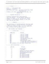
� <strong>Pro</strong>cedure:<br />
o Wire the bl<strong>in</strong>k1 circuit below on your robotic car’s breadboard.<br />
o <strong>Pro</strong>gram bl<strong>in</strong>k1.pbp <strong>in</strong>to the <strong>PIC</strong>16F88 follow<strong>in</strong>g the procedure to<br />
write, compile and download your program <strong>in</strong>to the <strong>PIC</strong> chip at the end<br />
of the lesson.<br />
o Install the 16F88 and test the circuit and program<br />
o Change the PAUSE values (tim<strong>in</strong>g values) and reprogram the chip.<br />
7
Cornerstone Electronics Technology and Robotics II<br />
<strong>PIC</strong> <strong>Microcontrollers</strong> <strong><strong>Pro</strong>gramm<strong>in</strong>g</strong> 1 LAB 1, Cont<strong>in</strong>ued<br />
� Challenges:<br />
o Connect the resistor and LED to RB1 and make it bl<strong>in</strong>k. Save the<br />
program as bl<strong>in</strong>krb1. Remember to change the TRISB register to<br />
make RB1 an output.<br />
o Railroad Cross<strong>in</strong>g: Wire a circuit us<strong>in</strong>g RB0 and RB1 as outputs and<br />
program the chip so that two LEDs alternate flashes like a railroad<br />
cross<strong>in</strong>g. Let the flash time be 0.75 seconds. Save the program as<br />
railrd1.<br />
o Drive a Motor: Design a circuit and program a <strong>PIC</strong>16F88 which will<br />
drive a motor <strong>in</strong> one direction only. Name the new program road1.<br />
� Use a 9 vdc power source on a separate breadboard to drive<br />
the motor.<br />
� Tie the grounds of the +5 vdc and +9 vdc breadboards<br />
together, but NOT the +5V and +9V power sources. Use two<br />
batteries for the power sources; one for the +5 vdc and the other<br />
for the +9 vdc bus rows.<br />
� Step down the +9 vdc to +5 vdc us<strong>in</strong>g a 78L05 voltage regulator<br />
circuit. Verify the +5 vdc and +9 vdc bus rows with a DMM.<br />
� You may use notes from prior classes to review NPN transistor<br />
switches.<br />
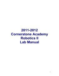
� H<strong>in</strong>ts:<br />
� Keep wires away from the 16F88 chip s<strong>in</strong>ce it will be<br />
removed frequently from the circuit.<br />
� Place the motor on the on the collector side of the NPN<br />
transistor. Place a 1K ohm resistor between the 16F88<br />
drive p<strong>in</strong> and the base of the NPN transistor. See the<br />
circuit below:<br />
Transistor Switch as a Motor Driver<br />
8
o Drive a Robot: Now comb<strong>in</strong>e this lesson’s circuitry and programm<strong>in</strong>g<br />
to drive your robotic car through the taped course without cross<strong>in</strong>g the<br />
<strong>in</strong>side boundaries of the tape. Revise the program road1.<br />
� You will have to use the process called dead reckon<strong>in</strong>g s<strong>in</strong>ce<br />
the robot is not equipped with any sensors. Wikipedia def<strong>in</strong>ition<br />
of dead reckon<strong>in</strong>g: Dead reckon<strong>in</strong>g is the process of estimat<strong>in</strong>g<br />
one's current position based upon a previously determ<strong>in</strong>ed<br />
position, or fix and advanc<strong>in</strong>g that position based upon known<br />
speed, elapsed time, and course.<br />
� H<strong>in</strong>ts:<br />
� Put the follow<strong>in</strong>g code at the end of the program:<br />
PORTB.0 = 0 ‘ Set PORTB, bit 1 to a LOW (0V)<br />
PORTB.1 = 0 ‘ Set PORTB, bit 2 to a LOW (0V)<br />
PAUSE 1 ‘ Pause 1 millisecond<br />
This code will stop the robotic car.<br />
9