MultiCon CMC-99/141 - Metrix Electronics Ltd
MultiCon CMC-99/141 - Metrix Electronics Ltd
MultiCon CMC-99/141 - Metrix Electronics Ltd

You also want an ePaper? Increase the reach of your titles
YUMPU automatically turns print PDFs into web optimized ePapers that Google loves.
Assisting the automation<br />
industry since 1986<br />
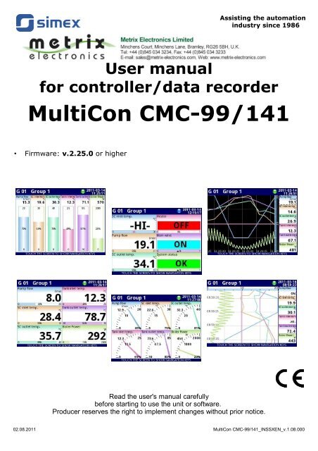
User manual<br />
for controller/data recorder<br />
<strong>MultiCon</strong> <strong>CMC</strong>-<strong>99</strong>/<strong>141</strong><br />
• Firmware: v.2.25.0 or higher<br />
Read the user's manual carefully<br />
before starting to use the unit or software.<br />
Producer reserves the right to implement changes without prior notice.<br />
02.08.2011 <strong>MultiCon</strong> <strong>CMC</strong>-<strong>99</strong>/<strong>141</strong>_INSSXEN_v.1.08.000
User manual for controller/data recorder <strong>MultiCon</strong> <strong>CMC</strong>-<strong>99</strong>/<strong>141</strong><br />
CONTENTS<br />
1. BASIC REQUIREMENTS AND USER SAFETY.......................................................................................4<br />
1.1. THE USE OF TOUCH-SCREEN.......................................................................................................5<br />
2. GENERAL CHARACTERISTICS...............................................................................................................5<br />
3. TECHNICAL DATA....................................................................................................................................8<br />
4. DEVICE INSTALLATION...........................................................................................................................9<br />
4.1. UNPACKING...................................................................................................................................10<br />
4.2. ASSEMBLY.....................................................................................................................................10<br />
4.3. CONNECTION METHOD...............................................................................................................13<br />
4.4. MAINTENANCE..............................................................................................................................21<br />
5. INTRODUCTION TO MULTICON <strong>CMC</strong>-<strong>99</strong>/<strong>141</strong>.......................................................................................21<br />
5.1. UNDERSTANDING CONTROLLER/DATA RECORDER MULTICON <strong>CMC</strong>-<strong>99</strong>/<strong>141</strong>.....................21<br />
5.1.1. Logical channels....................................................................................................................21<br />
5.1.2. Groups...................................................................................................................................23<br />
5.2. HARDWARE CONFIGURATIONS ................................................................................................23<br />
6. WORKING WITH THE MULTICON <strong>CMC</strong>-<strong>99</strong>/<strong>141</strong>....................................................................................24<br />
6.1. MULTICON <strong>CMC</strong>-<strong>99</strong>/<strong>141</strong> POWER UP...........................................................................................24<br />
6.2. THE USE OF THE TOUCH-SCREEN............................................................................................24<br />
6.3. DISPLAY.........................................................................................................................................25<br />
6.3.1. Information bar.......................................................................................................................25<br />
6.3.2. Navigation bar........................................................................................................................26<br />
6.3.3. Data panels............................................................................................................................27<br />
6.3.4. Important messages..............................................................................................................30<br />
7. CONFIGURATION OF THE MULTICON <strong>CMC</strong>-<strong>99</strong>/<strong>141</strong>...........................................................................30<br />
7.1. EDIT DIALOGUES..........................................................................................................................30<br />
7.2. MAIN MENU SELECTION PANEL.................................................................................................34<br />
7.3. FILES MANAGEMENT...................................................................................................................35<br />
7.4. DEVICE INFORMATION, LICENSE AND FIRMWARE UPDATE.................................................40<br />
7.5. DEVICE CONFIGURATION............................................................................................................41<br />
7.6. CONFIGURATION MENU STRUCTURE.......................................................................................44<br />
7.7. GENERAL SETTINGS....................................................................................................................48<br />
7.8. LOGICAL CHANNELS....................................................................................................................50<br />
7.8.1. Logical Channels - general settings......................................................................................51<br />
7.8.2. Logical channels in Hardware input mode............................................................................58<br />
7.8.3. Logical Channels in Hardware output monitor mode............................................................62<br />
7.8.4. Logical Channels in Modbus mode.......................................................................................64<br />
7.8.5. Logical Channels settings for Set point value mode.............................................................66<br />
7.8.6. Logical Channels settings for Math function mode...............................................................69<br />
7.8.7. Logical Channels settings for Controller mode......................................................................74<br />
7.8.8. Logical Channels settings for Profile/timer mode..................................................................76<br />
7.8.9. Logical Channels for Profile/timer (cycle counter) mode.....................................................77<br />
7.8.10. Examples of Logical Channels configuration......................................................................77<br />
7.9. BUILT-IN OUTPUTS.......................................................................................................................96<br />
7.9.1. Build-in outputs - general settings.........................................................................................97<br />
7.9.2. Built-in Output: Relay, Sound signal, Virtual relay................................................................98<br />
7.9.3. Build-in output: PWM mode for SSR relay output...............................................................102<br />
7.9.4. Build-in output - Current output...........................................................................................104<br />
7.9.5. Examples of build-in output configurations..........................................................................106<br />
7.10. EXTERNAL OUTPUTS...............................................................................................................107<br />
7.10.1. External outputs - general settings....................................................................................107<br />
7.10.2. External outputs - Control type = as a relay......................................................................109<br />
7.10.3. External outputs - Control type - as a linear output...........................................................110<br />
7.10.4. Examples of external output configurations......................................................................112<br />
7.11. PROFILES/TIMERS....................................................................................................................112<br />
7.11.1. Profile/timer - general settings...........................................................................................113<br />
7.11.2. Profiles/timers for triggering mode: level (gate), edge (once), edge (retrig.)....................116<br />
2<br />
<strong>Metrix</strong> <strong>Electronics</strong> <strong>Ltd</strong> Tel: +44 (0)845 034 3234 Email: sales@metrix-electronics.com
User manual for controller/data recorder <strong>MultiCon</strong> <strong>CMC</strong>-<strong>99</strong>/<strong>141</strong><br />
7.11.3. Profiles/timers for triggering mode: on time.......................................................................118<br />
7.11.4. Examples of Profile/timer configurations...........................................................................120<br />
7.12. CONTROLLERS.........................................................................................................................121<br />
7.12.1. Controllers - general settings.............................................................................................121<br />
7.12.2. Examples of Controller configurations...............................................................................124<br />
7.13. GROUPS.....................................................................................................................................125<br />
7.13.1. Groups - general settings..................................................................................................125<br />
7.13.2. Groups - Logging options..................................................................................................128<br />
7.13.3. Groups - Examples of visualisations of groups.................................................................129<br />
7.14. MODBUS.....................................................................................................................................131<br />
7.14.1. Modbus - general settings.................................................................................................132<br />
7.14.2. Modbus - SLAVE mode.....................................................................................................132<br />
7.14.2.1. Modbus SLAVE - The Modbus protocol handling.............................................133<br />
7.14.2.2. Modbus SLAVE - List of registers.....................................................................133<br />
7.14.2.3. Modbus SLAVE- Transmission errors handling................................................134<br />
7.14.2.4. Modbus SLAVE- Example of query/answer frames..........................................134<br />
7.14.3. Modbus - MASTER mode..................................................................................................135<br />
7.14.3.1. Modbus MASTER - Device templates parameter block....................................136<br />
7.14.3.2. Modbus MASTER- Device channels parameter block......................................137<br />
7.14.3.3. Modbus MASTER- Register blocks parameter block........................................<strong>141</strong><br />
7.14.4. Modbus - Register settings................................................................................................142<br />
7.14.5. Modbus - Example of Modbus protocol configuration in the device.................................143<br />
7.15. NETWORK SETTINGS...............................................................................................................150<br />
7.16. ACCESS OPTIONS....................................................................................................................151<br />
8. APPENDIX - INPUT AND OUTPUT MODULES DESCRIPTION.........................................................152<br />
8.1. PS3, PS4 - POWER SUPPLY MODULE......................................................................................152<br />
8.2. UI4, UI8, U16, I16, FI4 - VOLTAGE, CURENT AND FLOW MEASUREMENT MODULES.......153<br />
8.3. TC4, TC8 – THERMOCOUPLE SENSOR MEASUREMENT MODULES...................................157<br />
8.4. RT4 – RTD MEASUREMENT MODULE......................................................................................159<br />
8.5. UN3 – OPTOISOLATED UNIVERSAL INPUT MODULE.............................................................161<br />
8.6. D8, D16 – OPTOISOLATED DIGITAL INPUT MODULE.............................................................163<br />
8.7. CP4 – OPTOISOLATED UNIVERSAL COUNTER MODULES...................................................165<br />
8.8. S8, S16 - SOLID STATE RELAY DRIVERS MODULES.............................................................167<br />
8.9. R45, R81 - RELAY MODULES.....................................................................................................169<br />
8.10. IO2, IO4 – PASSIVE CURRENT OUTPUT................................................................................170<br />
8.11. COMMUNICATION MODULES..................................................................................................172<br />
Explanation of symbols used in the manual:<br />
!<br />
- This symbol denotes especially important guidelines concerning the installation and<br />
operation of the device. Not complying with the guidelines denoted by this symbol<br />
may cause an accident, damage or equipment destruction.<br />
i<br />
IF THE DEVICE IS NOT USED ACCORDING TO THE MANUAL THE USER IS<br />
RESPONSIBLE FOR POSSIBLE DAMAGES.<br />
- This symbol denotes especially important characteristics of the unit.<br />
Read any information regarding this symbol carefully<br />
3<br />
<strong>Metrix</strong> <strong>Electronics</strong> <strong>Ltd</strong> Tel: +44 (0)845 034 3234 Email: sales@metrix-electronics.com
User manual for controller/data recorder <strong>MultiCon</strong> <strong>CMC</strong>-<strong>99</strong>/<strong>141</strong><br />
1. BASIC REQUIREMENTS AND USER SAFETY<br />
!<br />
- The manufacturer is not responsible for any damages caused by<br />
inappropriate installation, not maintaining the proper environmental<br />
conditions and using the unit contrary to its assignment.<br />
- Installation should be conducted by qualified personnel . During installation all<br />
available safety requirements should be considered. The fitter is responsible<br />
for executing the installation according to this manual, local safety and EMC<br />
regulations.<br />
- GND input of device should be connected to PE wire;<br />
- The unit must be properly set-up, according to the application. Incorrect<br />
configuration can cause defective operation, which can lead to unit damage or<br />
an accident.<br />
- If in the case of a unit malfunction there is a risk of a serious threat to the<br />
safety of people or property additional, independent systems and<br />
solutions to prevent such a threat must be used.<br />
- The unit uses dangerous voltage that can cause a lethal accident. The<br />
unit must be switched off and disconnected from the power supply prior<br />
to starting installation of troubleshooting (in the case of malfunction).<br />
- Neighbouring and connected equipment must meet the appropriate of<br />
appropriate standards and regulations concerning safety and be equipped with<br />
adequate overvoltage and interference filters.<br />
- Do not attempt to disassemble, repair or modify the unit yourself. The unit<br />
has no user serviceable parts. Defective units must be disconnected and<br />
submitted for repairs at an authorized service centre.<br />
!<br />
!<br />
- In order to minimize fire or electric shock hazard, the unit must be protected<br />
against atmospheric precipitation and excessive humidity.<br />
- Do not use the unit in areas threatened with excessive shocks, vibrations, dust,<br />
humidity, corrosive gasses and oils.<br />
- Do not use the unit in areas where there is risk of explosions.<br />
- Do not use the unit in areas with significant temperature variations, exposure<br />
to condensation or ice.<br />
- Do not use the unit in areas exposed to direct sunlight.<br />
- Make sure that the ambient temperature (e.g. inside the control box) does not<br />
exceed the recommended values. In such cases forced cooling of the unit<br />
must be considered (e.g. by using a ventilator).<br />
The unit is designed for operation in an industrial environment and must<br />
not be used in a household environment or similar.<br />
4<br />
<strong>Metrix</strong> <strong>Electronics</strong> <strong>Ltd</strong> Tel: +44 (0)845 034 3234 Email: sales@metrix-electronics.com
User manual for controller/data recorder <strong>MultiCon</strong> <strong>CMC</strong>-<strong>99</strong>/<strong>141</strong><br />
1.1. THE USE OF TOUCH-SCREEN<br />
Do not use pointers with sharp edges (like tips of pencils and pens, knifes, scissors,<br />
needles, wires, nails, bolts etc.) while working with touch-screen. It is strongly recommended<br />
to use a special stylus made of plastic or another soft material with round ends (for example<br />
the stylus delivered with the device). The display of the <strong>MultiCon</strong> <strong>CMC</strong>-<strong>99</strong>/<strong>141</strong> should also be<br />
protected against aggressive substances and extremely high and low temperatures (see<br />
Chapter 3. Technical data).<br />
2. GENERAL CHARACTERISTICS<br />
The <strong>MultiCon</strong> <strong>CMC</strong>-<strong>99</strong>/<strong>141</strong> is a sophisticated multichannel unit which allows<br />
simultaneous measurement, visualisation and control of numerous channels. This device can<br />
operate autonomously or with cooperation with external measurement devices and actuators.<br />
Essential features of <strong>MultiCon</strong> <strong>CMC</strong>-<strong>99</strong>/<strong>141</strong> are listed and briefly described below.<br />
• Advanced processing unit and system based on LINUX<br />
The powerful <strong>MultiCon</strong> <strong>CMC</strong>-<strong>99</strong>/<strong>141</strong> processor allows the device to run under the control<br />
of a LINUX operating system. Such a solution makes the firmware flexible and gives the<br />
possibility of simultaneous operation of many processes (like: measurement,<br />
communication, visualisation). The use of LINUX also makes software independent of<br />
installed hardware.<br />
• Colour TFT display with Touch-panel<br />
The <strong>MultiCon</strong> <strong>CMC</strong>-<strong>99</strong>/<strong>141</strong> displays all data and dialogue on a legible, 320x240 pixels,<br />
colour TFT screen. Full control of the device is realised using the built-in touch-panel<br />
which makes operating the <strong>MultiCon</strong> <strong>CMC</strong>-<strong>99</strong>/<strong>141</strong> easy and intuitive.<br />
• Hardware flexibility and a large variety of possible configurations<br />
<strong>MultiCon</strong> <strong>CMC</strong>-<strong>99</strong>/<strong>141</strong> is designed as modular device consisting of a base and optional<br />
input and output modules. The base contains:<br />
– main processor,<br />
– display with touch-screen,<br />
– Switch Mode Power Supply<br />
• 19V...24...50V DC, 16V...24...35V AC<br />
• 85V...230...260V,<br />
– basic communication interfaces (USB and RS485).<br />
– three slots (marked as A, B, C) designed for installation of measurement and/or<br />
output modules.<br />
– one slot (marked as D) used for advanced communication module (additional USB<br />
Host, RS-485, RS-485/RS-232 and Ethernet).<br />
All measurement and output modules are optional and can be installed inside the device<br />
according to the customer's needs.<br />
Input modules that can be installed:<br />
– 4/8/16x Voltage/Current input module,<br />
– 4x RTD input module,<br />
– 4/8x TC input module,<br />
– 8/16x Optoisolated digital input.<br />
Output modules that can be installed:<br />
5<br />
<strong>Metrix</strong> <strong>Electronics</strong> <strong>Ltd</strong> Tel: +44 (0)845 034 3234 Email: sales@metrix-electronics.com
User manual for controller/data recorder <strong>MultiCon</strong> <strong>CMC</strong>-<strong>99</strong>/<strong>141</strong><br />
– 8/16x SSR driver module,<br />
– 4x Relay module 5A/250V,<br />
– 8x Relay module 1A/250V,<br />
– 2/4x Passive current output module.<br />
• Full freedom of data sources, presentation modes and controlling methods<br />
The multi level structure of the <strong>MultiCon</strong> <strong>CMC</strong>-<strong>99</strong>/<strong>141</strong> firmware allows for selection of<br />
presented data sources, presentation modes and controlling methods. The <strong>MultiCon</strong><br />
<strong>CMC</strong>-<strong>99</strong>/<strong>141</strong> displays the values of virtual logical channels which can be fed with:<br />
– measurement data from built-in physical channels,<br />
– measurement data from remote channels (other devices connected to the <strong>MultiCon</strong><br />
<strong>CMC</strong>-<strong>99</strong>/<strong>141</strong> by RS-485 interface),<br />
– output states and quantities (looped back results of controlling processes),<br />
– generate profiles/timers or also the mathematical combination of one or more<br />
logical channels.<br />
Build-in analog input<br />
Buid-in binary input<br />
External input (RS-485)<br />
Profiles/timers<br />
Controller<br />
Mathematical & logical combination data<br />
States of hardware & virtual outputs<br />
Set point values<br />
Interface<br />
Numeric, logical or text values<br />
Display<br />
Charts & bars<br />
Needles indicators<br />
Interface<br />
Reading data via Ethernet<br />
Reading data stored on the<br />
flash drive<br />
Grouping data<br />
Interface<br />
Build-in analog output<br />
Build-in binary output<br />
External output (RS-485)<br />
Fig. 2.1. Basic structure of the multichannel device<br />
6<br />
<strong>Metrix</strong> <strong>Electronics</strong> <strong>Ltd</strong> Tel: +44 (0)845 034 3234 Email: sales@metrix-electronics.com
User manual for controller/data recorder <strong>MultiCon</strong> <strong>CMC</strong>-<strong>99</strong>/<strong>141</strong><br />
All of these can be freely named and described by the user, and presented in many<br />
forms:<br />
– as numerical values,<br />
– vertical and horizontal charts,<br />
– vertical and horizontal bars,<br />
– as needle graphs.<br />
Every logical channel (visualised or not) can be used as input data for one or more<br />
controlling process. The <strong>MultiCon</strong> <strong>CMC</strong>-<strong>99</strong>/<strong>141</strong> implements many different controlling<br />
methods:<br />
– above defined level,<br />
– below defined level,<br />
– inside defined range,<br />
– outside of defined range<br />
– PID control.<br />
Process control with built-in outputs can be done with programmable hysteresis and<br />
delays of the outputs control. It is possible to control (linearly or bistably) remote<br />
modules. Controlling processes can drive built-in physical outputs or virtual outputs<br />
which can be used as inputs to logical channels.<br />
7<br />
<strong>Metrix</strong> <strong>Electronics</strong> <strong>Ltd</strong> Tel: +44 (0)845 034 3234 Email: sales@metrix-electronics.com
3. TECHNICAL DATA<br />
Power supply voltage<br />
(depending on version)<br />
External Fuse (required)<br />
Power consumption<br />
User manual for controller/data recorder <strong>MultiCon</strong> <strong>CMC</strong>-<strong>99</strong>/<strong>141</strong><br />
85...230...260V AC/DC; 50 ÷ 60 Hz<br />
or 19...24...50V DC; 16V...24...35V AC<br />
T - type, max. 2 A<br />
typically 15 VA; max. 20 VA<br />
Display (depending on version) 3.5” or 5.7”, TFT colour graphic display, 320 x 240<br />
pixels, with LED backlight<br />
Sensor power supply output<br />
Basic communication interfaces<br />
Digital input<br />
Optional communication module*<br />
Optional input modules*<br />
24V DC ± 5% / max. 200 mA,<br />
RS 485, 8N1/2, Modbus RTU, 1200 bit/s ÷ 115200 bit/s<br />
USB Host port, USB Device port<br />
1 input 0/15..24V DC, galvanic insulation (low state:<br />
0÷5V, high state:8÷24V)<br />
power consumption: 7,5 mA / 24V,<br />
insulation: 1min @ 500V DC.<br />
Second USB Host port<br />
Serial RS-485 and RS-485/RS-232<br />
Ethernet 10M RJ-45<br />
4/8/16x Voltage (0÷10V) / Current (0÷20mA)**<br />
4x RTD (Pt100, Pt500, Pt1000, Cu50, Cu100)**<br />
4/8x TC (J, K, S, T, N, R, B, E, L(GOST)**<br />
8/16x Digital input**<br />
Optional output modules* 4x Relay 5A/250V (cos ϕ = 1)**<br />
8x Relay 1A/250V (cos ϕ = 1)**<br />
8/16x SSR driver (10÷15V, up to 100mA per output)**<br />
2/4x IO Passive current output (4÷20mA)**<br />
Protection level<br />
USB interface on rear panel<br />
IP 65 (from front, after using waterproof frame)<br />
IP 54 (from front, with transparent door )<br />
IP 40 (from front, standard)<br />
IP 20 (housing and connection clips)<br />
Housing type<br />
Housing material<br />
Housing dimensions<br />
Mounting hole<br />
Assembly depth<br />
Panel thickness<br />
USB interface from front<br />
IP 54 (from front, with transparent door )<br />
IP 40 (from front, standard)<br />
IP 20 (housing and connection clips)<br />
panel<br />
NORYL - GFN2S E1<br />
96 x 96 x 100 mm (small housing)<br />
or 145 x 145 x 100 mm (big housing)<br />
90.5 x 90.5 mm (small housing)<br />
or 137 x 137 mm (big housing)<br />
102 mm<br />
max. 5 mm<br />
8<br />
<strong>Metrix</strong> <strong>Electronics</strong> <strong>Ltd</strong> Tel: +44 (0)845 034 3234 Email: sales@metrix-electronics.com
User manual for controller/data recorder <strong>MultiCon</strong> <strong>CMC</strong>-<strong>99</strong>/<strong>141</strong><br />
Operating temperature<br />
Storage temperature<br />
Humidity<br />
Altitude<br />
0°C to +50°C<br />
-10°C to +70°C<br />
5 to 90% no condensation<br />
up to 2000 meters above sea level<br />
Screws tightening max. torque 0,5 Nm<br />
Max. connection leads diameter 2,5 mm 2<br />
Safety requirements according to: PN-EN 61010-1<br />
installation category: II<br />
pollution degree: 2<br />
voltage in relation to ground: 300V AC<br />
insulation resistance: >20MΩ<br />
insulation strength between power supply and<br />
input/output terminal: 1min. @ 2300V (see Fig. 4.1)<br />
EMC PN-EN 61326-1<br />
Weight 340g (only base, see Fig. 4.8)<br />
* check the current list of measurement modules at producer's website<br />
** see the full specification in the appendix<br />
4. DEVICE INSTALLATION<br />
The unit has been designed and manufactured in a way assuring a high level of user<br />
safety and resistance to interference occurring in a typical industrial environment. In order to<br />
take full advantage of these characteristics installation of the unit must be conducted correctly<br />
and according to the local regulations.<br />
!<br />
!<br />
!<br />
- Read the basic safety requirements on page 4 prior to starting the installation.<br />
- Ensure that the power supply network voltage corresponds to the nominal<br />
voltage stated on the unit’s identification label.<br />
- The load must correspond to the requirements listed in the technical data.<br />
- All installation works must be conducted with a disconnected power supply.<br />
- Protecting the power supply connections against unauthorized persons must<br />
be taken into consideration.<br />
This is a class A unit. In a residential or a similar area it can cause radio<br />
frequency interference. In such cases the user can be requested to use<br />
appropriate preventive measures.<br />
Carefully check that the insulation used with the unit (Fig. 4.1) meets the<br />
expectations and if necessary use appropriate measures of over voltage protection.<br />
Additionally, insure the appropriate air and surface insulation gaps when installing.<br />
9<br />
<strong>Metrix</strong> <strong>Electronics</strong> <strong>Ltd</strong> Tel: +44 (0)845 034 3234 Email: sales@metrix-electronics.com
User manual for controller/data recorder <strong>MultiCon</strong> <strong>CMC</strong>-<strong>99</strong>/<strong>141</strong><br />
External sensor<br />
supply output<br />
Measurement inputs RS 485<br />
interface<br />
and<br />
digital input<br />
Internal circuits<br />
Power supply<br />
Outputs circuits<br />
Insulation strength 1min @ 2300V AC<br />
Insulation strength 1min @ 500V AC<br />
No insulation<br />
Fig. 4.1. Schematic diagram showing the insulation between individual circuits of the unit.<br />
4.1. UNPACKING<br />
After removing the unit from the protective packaging, check for transportation damage.<br />
Any transportation damage must be immediately reported to the carrier. Also, write down the<br />
unit serial number located on the housing and report the damage to the manufacturer.<br />
Attached with the unit please find:<br />
– assembly brackets - 2 pieces,<br />
– warranty,<br />
– user’s manual for <strong>MultiCon</strong> <strong>CMC</strong>-<strong>99</strong>/<strong>141</strong> unit (device)<br />
4.2. ASSEMBLY<br />
!<br />
- The unit is designed for mounting inside housings (control panel, switchboard)<br />
insuring appropriate protection against surges and interference. Metal<br />
housings must be connected to ground in a way that complies with the<br />
governing regulations.<br />
- Disconnect the power supply prior to starting assembly.<br />
- Check the connections are wired correctly prior to switching the unit on.<br />
In order to install the unit, a mounting hole must be prepared according to Fig. 4.2.<br />
The thickness of the material of which the panel is made must not exceed 5mm.<br />
When preparing the mounting hole take the grooves for catches located on both<br />
sides of the housing into consideration (Fig. 4.2). Place the unit in the mounting<br />
hole inserting it from the front side of the panel, and then fix it using the brackets<br />
10<br />
<strong>Metrix</strong> <strong>Electronics</strong> <strong>Ltd</strong> Tel: +44 (0)845 034 3234 Email: sales@metrix-electronics.com
User manual for controller/data recorder <strong>MultiCon</strong> <strong>CMC</strong>-<strong>99</strong>/<strong>141</strong><br />
(Fig. 4.4). The minimum distances between the center points of multiple units - due<br />
to the thermal and mechanical conditions of operation - are shown on Fig. 4.3.<br />
W<br />
Small housing:<br />
H, W = 90.5 mm<br />
h = 16 mm<br />
h<br />
8 mm<br />
Big housing:<br />
H, W = 137 mm<br />
h= 38.5 mm<br />
H<br />
8 mm<br />
h<br />
1 mm<br />
1 mm max. 5 mm<br />
Fig. 4.2. Mounting hole dimensions<br />
W<br />
Small housing:<br />
H, W = 115 mm<br />
Big housing:<br />
H, W = 165 mm<br />
H<br />
Fig. 4.3. Minimum distances when assembly of a number of units<br />
11<br />
<strong>Metrix</strong> <strong>Electronics</strong> <strong>Ltd</strong> Tel: +44 (0)845 034 3234 Email: sales@metrix-electronics.com
User manual for controller/data recorder <strong>MultiCon</strong> <strong>CMC</strong>-<strong>99</strong>/<strong>141</strong><br />
98 mm<br />
8 mm<br />
removable terminals<br />
Fig. 4.4. Installing of brackets<br />
To avoid connectors slots destruction use the method shown on Fig. 4.5<br />
GOOD<br />
back side<br />
of device<br />
connector<br />
WRONG<br />
back side<br />
of device<br />
connector<br />
Fig. 4.5. Connectors removing method<br />
12<br />
<strong>Metrix</strong> <strong>Electronics</strong> <strong>Ltd</strong> Tel: +44 (0)845 034 3234 Email: sales@metrix-electronics.com
4.3. CONNECTION METHOD<br />
Caution<br />
!<br />
User manual for controller/data recorder <strong>MultiCon</strong> <strong>CMC</strong>-<strong>99</strong>/<strong>141</strong><br />
- Installation should be conducted by qualified personnel. During installation all<br />
available safety requirements should be considered. The fitter is responsible for<br />
executing the installation according to this manual, local safety and EMC<br />
regulations.<br />
- The unit is not equipped with an internal fuse or power supply circuit breaker.<br />
Because of this an external time-delay cut-out fuse with a small nominal current<br />
value must be used (recommended bipolar, max. 2A) and a power supply circuitbreaker<br />
located near the unit. In the case of using a monopolar fuse it must be<br />
mounted on the active wire (L).<br />
- The power supply network cable diameter must be selected in such a way that in<br />
the case of a short circuit of the cable from the side of the unit the cable shall be<br />
protected against destruction with an electrical installation fuse.<br />
- Wiring must meet appropriate standards and local regulations and laws.<br />
- In order to secure against accidental short circuit the connection cables must be<br />
terminated with appropriate insulated cable tips.<br />
- Tighten the clamping screws. The recommended tightening torque is 0.5 Nm.<br />
Loose screws can cause fire or defective operation. Over tightening can lead to<br />
damaging the connections inside the units and breaking the thread.<br />
- In the case of the unit being fitted with separable clamps they should be inserted<br />
into appropriate connectors in the unit, even if they are not used for any<br />
connections.<br />
- Unused terminals (marked as n.c.) must not be used for connecting any<br />
connecting cables (e.g. as bridges), because this can cause damage to the<br />
equipment or electric shock.<br />
- If the unit is equipped with housing, covers and sealing to protecting against<br />
water intrusion, pay special attention to their correct tightening or clamping. In the<br />
case of any doubt consider using additional preventive measures (covers, roofing,<br />
seals, etc.). Carelessly executed assembly can increase the risk of electric shock.<br />
- After the installation is completed do not touch the unit’s connections when it is<br />
switched on, because it carries the risk of electrical shock.<br />
13<br />
<strong>Metrix</strong> <strong>Electronics</strong> <strong>Ltd</strong> Tel: +44 (0)845 034 3234 Email: sales@metrix-electronics.com
User manual for controller/data recorder <strong>MultiCon</strong> <strong>CMC</strong>-<strong>99</strong>/<strong>141</strong><br />
Due to possible significant interference in industrial installations appropriate measures<br />
assuring correct operation of the unit must be applied. To avoid the unit of improper<br />
indications keep recommendations listed below.<br />
N<br />
L<br />
1<br />
2<br />
!<br />
FUSE<br />
N<br />
L<br />
Depending on version:<br />
85...230...260V AC/DC or<br />
19...24...50V DC; 16...24...35V AC<br />
Fig. 4.6. Connection of power supply<br />
• Avoid running signal cables and transmission cables together with power supply cables<br />
and cables controlling inductive loads (e.g. contactors). Such cables should cross at a<br />
right angle.<br />
• Contactor coils and inductive loads should be equipped with interference protection<br />
systems, e.g. RC-type.<br />
• Use of screened signal cables is recommended. Signal cable screens should be<br />
connected to the earthing only at one of the ends of the screened cable.<br />
• In the case of magnetically induced interference the use of twisted pair signal cables is<br />
recommended. Twisted pair (best if shielded) must be used with RS-485 serial<br />
transmission connections.<br />
• In the case of measurement or control signals are longer than 30m or go outside of the<br />
building then additional safety circuits are required.<br />
• In the case of interference from the power supply side the use of appropriate interference<br />
filters is recommended. Bear in mind that the connection between the filter and the unit<br />
should be as short as possible and the metal housing of the filter must be connected to<br />
the earth with the largest possible surface. The cables connected to the filter output must<br />
not be run with cables with interference (e.g. circuits controlling relays or contactors).<br />
Connections of power supply voltage and measurement signals are executed using the<br />
screw connections on the back of the unit’s housing.<br />
max. 1.5 mm<br />
5-6 mm<br />
!<br />
Fig. 4.7. Method of cable insulation replacing and cable terminals dimensions<br />
All connections must be made while power supply is disconnected !<br />
14<br />
<strong>Metrix</strong> <strong>Electronics</strong> <strong>Ltd</strong> Tel: +44 (0)845 034 3234 Email: sales@metrix-electronics.com
User manual for controller/data recorder <strong>MultiCon</strong> <strong>CMC</strong>-<strong>99</strong>/<strong>141</strong><br />
Slot D<br />
Slot C<br />
Slot B<br />
Slot A<br />
1<br />
2<br />
Power supply<br />
(depending on version)<br />
USB<br />
device<br />
3<br />
4<br />
5<br />
6<br />
7<br />
8<br />
GND<br />
GND<br />
B-<br />
A+<br />
+24V DC ±5%<br />
Imax. = 200mA<br />
digital input<br />
0/15..24V DC<br />
RS-485<br />
insulated<br />
Fig. 4.8. Terminals description<br />
The basic performance of the device (see Fig. 4.8) contains only the extreme left<br />
terminals:<br />
• Power supply,<br />
• USB device port,<br />
• Sensor supply output +24V DC Imax=200mA,<br />
• Digital input 0V...15...24V DC (low state: 0÷5V, high state:8÷24V)<br />
• Interface RS-485,<br />
i<br />
– In case of UN3 module installed , there is no +24V DC output and this terminal stay<br />
not connected. This limitation is temporary and will be removed soon.<br />
Depending on customer's needs, the basic version of the device can be upgraded with up to:<br />
• three I / O modules (installed in a place designated as Slot A, Slot B Slot C),<br />
• advanced communication module (additional serial, USB and Ethernet interfaces).<br />
According to the order these terminals can look different than shown in Fig. 4.8 or be not<br />
present. Terminals and connections of available modules are shown on Fig. 4.9-4.14.<br />
Shown below is an example of a configuration of the installed modules:<br />
• base,<br />
• Slot A - UI8 module (8 current input & 8 voltage input),<br />
• Slot B - RT4 module (4 RTD input),<br />
• Slot C - R81 module (8 relay output 1A/250V),<br />
• Slot D - ACM module (additional serial, USB and Ethernet interfaces).<br />
15<br />
<strong>Metrix</strong> <strong>Electronics</strong> <strong>Ltd</strong> Tel: +44 (0)845 034 3234 Email: sales@metrix-electronics.com
User manual for controller/data recorder <strong>MultiCon</strong> <strong>CMC</strong>-<strong>99</strong>/<strong>141</strong><br />
Available modules:<br />
UI8<br />
8 current + 8 voltage inputs<br />
n01<br />
n02<br />
n03<br />
n04<br />
n05 GND<br />
n06<br />
n07<br />
n08<br />
n09<br />
n10 GND<br />
n11<br />
n12<br />
n13<br />
n14<br />
n15 GND<br />
n16<br />
n17<br />
n18<br />
n19<br />
n20 GND<br />
AIN1<br />
AIN2<br />
AIN3<br />
AIN4<br />
AIN5<br />
AIN6<br />
AIN7<br />
AIN8<br />
AIN9<br />
AIN10<br />
AIN11<br />
AIN12<br />
AIN13<br />
AIN14<br />
AIN15<br />
AIN16<br />
4 x 0-20mA<br />
4 x 0-20mA<br />
4 x 0-10V<br />
4 x 0-10V<br />
UI4<br />
4 current + 4 voltage inputs<br />
n01<br />
n02<br />
n03<br />
n04<br />
n05 GND<br />
n06<br />
n07<br />
n08<br />
n09<br />
n10 GND<br />
AIN1<br />
AIN2<br />
AIN3<br />
AIN4<br />
AIN5<br />
AIN6<br />
AIN7<br />
AIN8<br />
4 x 0-20mA<br />
4 x 0-10V<br />
I16<br />
16 current inputs<br />
n01 AIN1<br />
n02 AIN2<br />
n03 AIN3<br />
n04 AIN4<br />
n05 GND<br />
n06<br />
n07<br />
n08<br />
n09<br />
n10 GND<br />
n11<br />
n12<br />
n13<br />
n14<br />
n15 GND<br />
n16<br />
n17<br />
n18<br />
n19<br />
n20 GND<br />
AIN5<br />
AIN6<br />
AIN7<br />
AIN8<br />
AIN9<br />
AIN10<br />
AIN11<br />
AIN12<br />
AIN13<br />
AIN14<br />
AIN15<br />
AIN16<br />
4 x 0-20mA<br />
4 x 0-20mA<br />
4 x 0-20mA<br />
4 x 0-20mA<br />
U16<br />
16 voltage inputs<br />
AIN1<br />
n01<br />
AIN2<br />
n02<br />
n03 AIN3<br />
n04 AIN4<br />
n05 GND<br />
n06<br />
n07<br />
n08<br />
n09<br />
n10 GND<br />
n11<br />
n12<br />
n13<br />
n14<br />
n15 GND<br />
n16<br />
n17<br />
n18<br />
n19<br />
n20 GND<br />
AIN5<br />
AIN6<br />
AIN7<br />
AIN8<br />
AIN9<br />
AIN10<br />
AIN11<br />
AIN12<br />
AIN13<br />
AIN14<br />
AIN15<br />
AIN16<br />
4 x 0-10V<br />
4 x 0-10V<br />
4 x 0-10V<br />
4 x 0-10V<br />
Fig. 4.9. Available current and voltage input modules<br />
FI4<br />
4 flowmeter inputs<br />
+ 4 current inputs<br />
n01<br />
n02<br />
n03<br />
n04<br />
n05 GND<br />
n06<br />
n07<br />
n08<br />
n09<br />
n10 GND<br />
AIN1<br />
AIN2<br />
AIN3<br />
AIN4<br />
AIN5<br />
AIN6<br />
AIN7<br />
AIN8<br />
4 x 0-20mA<br />
(flowmeters)<br />
4 x 0-20mA<br />
Fig. 4.10. Available flowmeter modules<br />
16<br />
<strong>Metrix</strong> <strong>Electronics</strong> <strong>Ltd</strong> Tel: +44 (0)845 034 3234 Email: sales@metrix-electronics.com
User manual for controller/data recorder <strong>MultiCon</strong> <strong>CMC</strong>-<strong>99</strong>/<strong>141</strong><br />
UN3<br />
3 universal inputs<br />
+<br />
n01<br />
V, mA<br />
-<br />
n02<br />
n03<br />
n04<br />
n05<br />
n06<br />
n07<br />
n08<br />
n09<br />
n10<br />
n11<br />
n12<br />
n13<br />
n14<br />
n15<br />
TC, mV<br />
+<br />
RTD<br />
+<br />
-<br />
TC, mV<br />
+<br />
RTD<br />
+<br />
-<br />
TC, mV<br />
+<br />
RTD<br />
AIN1<br />
AIN2<br />
AIN3<br />
Fig. 4.11. Available universal input modules<br />
RT4<br />
4 RTD inputs<br />
n01<br />
n02<br />
n03<br />
n04<br />
n05<br />
n06<br />
n07<br />
n08<br />
n09<br />
n10<br />
n11<br />
n12<br />
n13<br />
n14<br />
n15<br />
n16<br />
AIN1<br />
AIN2<br />
AIN3<br />
AIN4<br />
TC4<br />
4 thermocouple inputs<br />
n01 -<br />
AIN1<br />
n02 +<br />
-<br />
n03<br />
n04<br />
+<br />
AIN2<br />
n05 -<br />
AIN3<br />
n06 +<br />
-<br />
n07<br />
AIN4<br />
n08<br />
+<br />
Fig. 4.12. Available RTD and TC input modules<br />
TC8<br />
8 thermocouple inputs<br />
n01 -<br />
AIN1<br />
n02 +<br />
-<br />
n03<br />
AIN2<br />
n04<br />
+<br />
n05 -<br />
AIN3<br />
n06 +<br />
-<br />
n07<br />
AIN4<br />
n08<br />
+<br />
n09 -<br />
n10 +<br />
-<br />
n11<br />
n12<br />
+<br />
n13 -<br />
n14 +<br />
-<br />
n15<br />
n16<br />
+<br />
AIN5<br />
AIN6<br />
AIN7<br />
AIN8<br />
17<br />
<strong>Metrix</strong> <strong>Electronics</strong> <strong>Ltd</strong> Tel: +44 (0)845 034 3234 Email: sales@metrix-electronics.com
User manual for controller/data recorder <strong>MultiCon</strong> <strong>CMC</strong>-<strong>99</strong>/<strong>141</strong><br />
CP4<br />
4 universal counters<br />
n01<br />
n02<br />
n03<br />
n04<br />
n05<br />
n06<br />
n07<br />
n08<br />
n09<br />
n10<br />
n11<br />
n12<br />
n13<br />
n14<br />
n15<br />
n16<br />
n17<br />
n18<br />
n19<br />
n20<br />
Inp11<br />
Inp12<br />
Prg1<br />
Res1<br />
COM1<br />
Inp21<br />
Inp22<br />
Prg2<br />
Res2<br />
COM2<br />
Inp31<br />
Inp32<br />
Prg3<br />
Res3<br />
COM3<br />
Inp41<br />
Inp42<br />
Prg4<br />
Res4<br />
COM4<br />
Counter 1<br />
Counter 2<br />
Counter 3<br />
Counter 4<br />
D16<br />
16 Digital inputs<br />
n01<br />
n02<br />
n03<br />
n04<br />
n05<br />
n06<br />
n07<br />
DIN1<br />
DIN2<br />
DIN3<br />
DIN4<br />
COM 1-4<br />
DIN5<br />
DIN6<br />
DIN17<br />
n08<br />
n09<br />
n10<br />
n11<br />
n12<br />
DIN7<br />
DIN8<br />
COM 5-8<br />
DIN9<br />
DIN10<br />
DIN18<br />
n13<br />
n14<br />
n15<br />
DIN11<br />
DIN12<br />
COM 9-12<br />
DIN19<br />
n16<br />
n17<br />
n18<br />
n19<br />
DIN13<br />
DIN14<br />
DIN15<br />
DIN16<br />
DIN20<br />
n20 COM 13-16<br />
DIN21<br />
D8<br />
8 Digital inputs<br />
n01 DIN1<br />
n02 DIN2<br />
n03 DIN3<br />
DIN9<br />
n04 DIN4<br />
n05 COM 1-4<br />
n06 DIN5<br />
n07 DIN6<br />
n08 DIN7<br />
DIN10<br />
n09 DIN8<br />
n10 COM 5-8<br />
DIN11<br />
Fig. 4.13. Available Counters and Digital input modules<br />
18<br />
<strong>Metrix</strong> <strong>Electronics</strong> <strong>Ltd</strong> Tel: +44 (0)845 034 3234 Email: sales@metrix-electronics.com
User manual for controller/data recorder <strong>MultiCon</strong> <strong>CMC</strong>-<strong>99</strong>/<strong>141</strong><br />
R81<br />
8 relay outputs 1A/250V<br />
n01<br />
n02<br />
n03<br />
n04<br />
n05<br />
n06<br />
n07<br />
n08<br />
n09<br />
n10<br />
n11<br />
n12<br />
n13<br />
n14<br />
R2 R1<br />
R4 R3<br />
R5<br />
R6<br />
R7<br />
R8<br />
R45<br />
4 relay outputs 5A/250V<br />
n01<br />
n02<br />
n03<br />
n04<br />
n05<br />
n06<br />
n07<br />
n08<br />
n09<br />
n10<br />
n11<br />
n12<br />
R1<br />
R2<br />
R3<br />
R4<br />
S16<br />
16 SSR outputs<br />
n01<br />
n02<br />
n03<br />
n04<br />
n05<br />
+10..24V DC<br />
SSR1<br />
SSR2<br />
SSR3<br />
SSR4<br />
n06 SSR5<br />
n07 SSR6<br />
n08 SSR7<br />
n09 SSR8<br />
n10 GND<br />
n11<br />
n12<br />
+10..24V DC<br />
SSR9<br />
n13 SSR10<br />
n14 SSR11<br />
n15 SSR12<br />
n16 SSR13<br />
n17 SSR14<br />
n18 SSR15<br />
n19 SSR16<br />
n20 GND<br />
Fig. 4.14. Available output modules<br />
S8<br />
8 SSR outputs<br />
+10..24V DC<br />
n01<br />
n02 SSR1<br />
n03 SSR2<br />
n04 SSR3<br />
n05 SSR4<br />
n06 SSR5<br />
n07 SSR6<br />
n08 SSR7<br />
n09 SSR8<br />
n10 GND<br />
IO4<br />
4 current output<br />
IO2<br />
2 current output<br />
n01<br />
n02<br />
PASSIVE<br />
AOUT 4<br />
n03<br />
n04<br />
PASSIVE<br />
AOUT 3<br />
n05<br />
n06<br />
PASSIVE<br />
AOUT 2<br />
n05<br />
n06<br />
PASSIVE<br />
AOUT 2<br />
n07<br />
n08<br />
PASSIVE<br />
AOUT 1<br />
n07<br />
n08<br />
PASSIVE<br />
AOUT 1<br />
19<br />
<strong>Metrix</strong> <strong>Electronics</strong> <strong>Ltd</strong> Tel: +44 (0)845 034 3234 Email: sales@metrix-electronics.com
User manual for controller/data recorder <strong>MultiCon</strong> <strong>CMC</strong>-<strong>99</strong>/<strong>141</strong><br />
Fig. 4.15. Available passive current output<br />
insulated insulated<br />
RS-485<br />
RS-232 + RS-485<br />
9<br />
10<br />
11<br />
12<br />
13<br />
14<br />
15<br />
16<br />
17<br />
18<br />
19<br />
GND RS (2)<br />
B- (2)<br />
A+ (2)<br />
GND RS (3)<br />
B- (3)<br />
A+ (3)<br />
GND RS (3)<br />
RxD (3)<br />
TxD (3)<br />
CTS (3)<br />
RTS (3)<br />
USB<br />
host<br />
RJ-45<br />
ETH<br />
Fig. 4.16. ACM communication module<br />
RS-485<br />
6<br />
7<br />
8<br />
GND<br />
B-<br />
A+<br />
RS232/RS485<br />
or USB/RS485<br />
interface<br />
Fig. 4.17. Connection of RS-485 transmission signals<br />
The <strong>MultiCon</strong> <strong>CMC</strong>-<strong>99</strong>/<strong>141</strong> device supports the following converters:<br />
– USB / RS-485 converter (SRS-USB/4-Z45)<br />
– RS-232 / RS-485 converter (SRS-2/4-Z45)<br />
20<br />
<strong>Metrix</strong> <strong>Electronics</strong> <strong>Ltd</strong> Tel: +44 (0)845 034 3234 Email: sales@metrix-electronics.com
User manual for controller/data recorder <strong>MultiCon</strong> <strong>CMC</strong>-<strong>99</strong>/<strong>141</strong><br />
4.4. MAINTENANCE<br />
The unit does not have any internal replaceable or adjustable components available to<br />
the user. Pay attention to the ambient temperature in the room where the unit is operating.<br />
Excessively high temperatures cause faster ageing of the internal components and shorten<br />
the fault-free time of the unit's operation.<br />
In cases where the unit gets dirty do not clean with solvents. For cleaning use warm water<br />
with small amount of detergent or in the case of more significant contamination ethyl or<br />
isopropyl alcohol.<br />
!<br />
Using any other agents can cause permanent damage to the housing.<br />
Product marked with this symbol should not be placed in municipal waste. Please<br />
check local regulations for disposal of electronic products.<br />
5. INTRODUCTION TO <strong>MultiCon</strong> <strong>CMC</strong>-<strong>99</strong>/<strong>141</strong><br />
5.1. UNDERSTANDING CONTROLLER/DATA RECORDER <strong>MultiCon</strong> <strong>CMC</strong>-<strong>99</strong>/<strong>141</strong><br />
The <strong>MultiCon</strong> <strong>CMC</strong>-<strong>99</strong>/<strong>141</strong> device was developed as a universal multichannel<br />
controller. To maintain this concept its firmware was written with multi level structure. The<br />
device runs under the control of a LINUX operating system keeping all subsystems ready to<br />
use and allowing independent and simultaneous operation of many processes<br />
(communication, data acquisition, post-processing, visualisation etc.). Such an approach<br />
gives great advantages to high level applications, making it flexible and dynamically<br />
configurable. Similarly data structures and streams were implemented in quite a different way<br />
than in most similar devices. The main difference is the concept of using Logical Channels<br />
as a bridge: physical inputs and outputs - visualisation and controlling processes. Designers<br />
of <strong>MultiCon</strong> <strong>CMC</strong>-<strong>99</strong>/<strong>141</strong> decided to use such solution to increase functionality of the device<br />
and make software near fully independent on the hardware.<br />
5.1.1. Logical channels<br />
A Logical Channel is a data stream existing in the memory of the device, having it's<br />
own name and can be displayed in almost any way. Logical Channels can be used as:<br />
– measurement inputs,<br />
– data source of control loop,<br />
– control source of the physical outputs,<br />
– input data to other Logical Channels,<br />
– data source for visualisation and logging.<br />
21<br />
<strong>Metrix</strong> <strong>Electronics</strong> <strong>Ltd</strong> Tel: +44 (0)845 034 3234 Email: sales@metrix-electronics.com
User manual for controller/data recorder <strong>MultiCon</strong> <strong>CMC</strong>-<strong>99</strong>/<strong>141</strong><br />
Hardware input<br />
Digital input<br />
Analog input<br />
Digital input 24V<br />
Virtual demo input<br />
(sinus, tringle,<br />
rectangular)<br />
Output monitor<br />
Relays<br />
Sound signal<br />
Virtual relay<br />
1<br />
2<br />
...<br />
Bi<br />
1<br />
2<br />
...<br />
Ai<br />
X2<br />
X3<br />
X4<br />
X5<br />
Set point value<br />
Value -<strong>99</strong><strong>99</strong>9÷<strong>99</strong><strong>99</strong>9<br />
Math function<br />
Function<br />
1<br />
2<br />
...<br />
Rel<br />
X1<br />
V1<br />
V2<br />
...<br />
V16<br />
Modbus<br />
port address input<br />
1 1<br />
1 ... ...<br />
255 100<br />
Modbus input<br />
1 1<br />
2 .. ...<br />
255 100<br />
1 1<br />
MP ... ...<br />
255 100<br />
1<br />
2<br />
...<br />
F<br />
Logical<br />
channel<br />
1<br />
2<br />
3<br />
4<br />
5<br />
...<br />
...<br />
...<br />
...<br />
...<br />
...<br />
LC<br />
Controller<br />
1<br />
2<br />
Controller<br />
...<br />
C<br />
Built-in output<br />
1<br />
2<br />
Relay<br />
...<br />
Rel<br />
X1 Sound signal<br />
V1<br />
V2<br />
Virtual relay<br />
...<br />
V16<br />
External output<br />
output address port<br />
1 1<br />
... ... 1<br />
100 255<br />
1 1<br />
... ...<br />
100 255<br />
1 11<br />
... ...<br />
100 255<br />
Slot<br />
1<br />
...<br />
6<br />
1<br />
...<br />
6<br />
1<br />
...<br />
6<br />
...<br />
Profile/timer<br />
1<br />
2<br />
Profile/timer<br />
...<br />
P/t<br />
2<br />
MP<br />
Groups<br />
Group<br />
1<br />
2<br />
G<br />
Remote<br />
Modbus<br />
output<br />
Visualization<br />
& logging<br />
(optional)<br />
Fig. 5.1. The overall connections structure of the Logical channel with the device I /O<br />
Fig. 5.1 shows general structure of of connections between logical channels, and device<br />
inputs/outputs. Each of Logical Channels can be configured to represent:<br />
– measurement data from built-in physical input channels,<br />
– output data and states of physical output channels,<br />
– output data and states of external modules connected to <strong>MultiCon</strong> <strong>CMC</strong>-<strong>99</strong>/<strong>141</strong> via<br />
RS-485 interface,<br />
– states and data coming from outputs of controlling processes,<br />
– generated profile/timer<br />
– states of virtual input channels, and timers,<br />
– mathematical combination of other Logical Channels.<br />
22<br />
<strong>Metrix</strong> <strong>Electronics</strong> <strong>Ltd</strong> Tel: +44 (0)845 034 3234 Email: sales@metrix-electronics.com
User manual for controller/data recorder <strong>MultiCon</strong> <strong>CMC</strong>-<strong>99</strong>/<strong>141</strong><br />
More information about Logical channels and samples of configuration Logical channels are<br />
presented in Chapter 7.8 Logical channels.<br />
To make visualization clearer Logical Channels can be gather into Groups.<br />
5.1.2. Groups<br />
A Group is a set of 1-6 Logical Channels. The <strong>MultiCon</strong> <strong>CMC</strong>-<strong>99</strong>/<strong>141</strong> can show on the<br />
same screen only channels belonging to the same Group, additionally each Group has its<br />
own individual name making operation with the device very clear. Every Logical Channel can<br />
belong to one or more groups simultaneously, and also not to belong to any group (then it will<br />
not be shown, but it can still be used for other processes). It is common that channels<br />
belonging to the same Group are related to one another in some way (for example<br />
representing parameters of single object or representing similar parameters of few separate<br />
objects) but it is also possible to create a Group consisting of completely unrelated channels.<br />
Logical channels<br />
1 2 3 4 5 6 7 8 9 10<br />
60<br />
Groups<br />
1 2 3 4 5 6 7 8 9 10<br />
Visualization and logging<br />
1 2 3 5 6 7 8 9 10<br />
Fig. 5.2. An overview of the concept of Group in the device<br />
Using Groups, Logical Channels and mathematical combinations of them gives incredible<br />
flexibility to the software, allowing for ease in designing advanced control methods and<br />
visualisation with a low cost <strong>MultiCon</strong> <strong>CMC</strong>-<strong>99</strong>/<strong>141</strong>.<br />
More information about Groups and samples of Group configurations are presented in<br />
Chapter 7.13 Groups.<br />
5.2. HARDWARE CONFIGURATIONS<br />
The functionality of <strong>MultiCon</strong> <strong>CMC</strong>-<strong>99</strong>/<strong>141</strong> can fit to the user's needs. The base of the<br />
<strong>MultiCon</strong> <strong>CMC</strong>-<strong>99</strong>/<strong>141</strong> contains: the main processor, display with touch-screen, Switch Mode<br />
Power Supply (in one of two versions: 19V...24...50V DC 16V...24...35V AC and 85V..230..260V<br />
AC) and basic communication interfaces like USB and RS485. See Fig. 4.8 - most far left<br />
connectors. All other modules are optional and can be installed inside the device according to<br />
23<br />
<strong>Metrix</strong> <strong>Electronics</strong> <strong>Ltd</strong> Tel: +44 (0)845 034 3234 Email: sales@metrix-electronics.com
User manual for controller/data recorder <strong>MultiCon</strong> <strong>CMC</strong>-<strong>99</strong>/<strong>141</strong><br />
customer's needs. Next to the basic connectors is the slot for an advanced communication<br />
module. In the simplest version this module can be equipped only with rear USB Host<br />
connector (this is standard for the IP-65 version of the <strong>MultiCon</strong> <strong>CMC</strong>-<strong>99</strong>/<strong>141</strong>). The full<br />
version of this module contains also 2 additional serial ports (RS485 and RS485/RS232) and<br />
a 10Mb Ethernet RJ-45 connector (see Fig. 4.16).<br />
Three slots designed for built-in hardware inputs and outputs are installed on the right<br />
side of the case (see Fig. 4.8, terminals marked: slot A, slot B and slot C). The number and<br />
size of these terminals varies depending on module type. Brief descriptions of available<br />
modules are shown in Fig. 4.9-4.16. Measurement and actuator modules are constantly being<br />
developed, so the current list of available modules varies (visit manufacturers website to<br />
check current list of <strong>MultiCon</strong> <strong>CMC</strong>-<strong>99</strong>/<strong>141</strong> modules).<br />
Basic measurement modules are:<br />
– 4/8/16x Voltage/Current input module,<br />
– 4x RTD input module,<br />
– 4/8x TC input module.<br />
Output modules are:<br />
– 8/16x SSR driver module,<br />
– 8x Relay 1A/250V module,<br />
– 4x Relay 5A/250V module,<br />
– 2/4x IO passive current output.<br />
Communication module:<br />
– ACM - advanced communication module.<br />
6. WORKING WITH THE <strong>MultiCon</strong> <strong>CMC</strong>-<strong>99</strong>/<strong>141</strong><br />
6.1. <strong>MultiCon</strong> <strong>CMC</strong>-<strong>99</strong>/<strong>141</strong> POWER UP<br />
After powering up a starting Logo is showed on the <strong>MultiCon</strong> <strong>CMC</strong>-<strong>99</strong>/<strong>141</strong> display.<br />
While the operating system is being loaded a progress bar is visible in the middle of the<br />
screen. During this process the view of screen may stay dimmed for 3-5 seconds. Please wait<br />
until the end of this operation before starting to operate the device. After that the main<br />
application is started. The view of the main program depends of the General settings (see<br />
the Chapter 7.8.1Logical Channels - general settings) and Group settings (see Chapter<br />
7.13 Groups). An example view of the main program shown in Fig. 6.1.<br />
6.2. THE USE OF THE TOUCH-SCREEN<br />
Do not use pointers with sharp edges (like tips of pencils and pens, knifes, scissors,<br />
needles, wires, nails, bolts etc.) while working with touch-screen. It is strongly recommended<br />
to use a special stylus made of plastic or another soft material with round ends (for example<br />
the stylus delivered with the device) or a finger. The display of the <strong>MultiCon</strong> <strong>CMC</strong>-<strong>99</strong>/<strong>141</strong><br />
should also be protected against aggressive substances and extremely high and low<br />
temperature(see technical data in Chapter 3 Technical data).<br />
i<br />
To clean the LCD screen you should use a special detergent designed for LCDs<br />
and a soft cloth.<br />
24<br />
<strong>Metrix</strong> <strong>Electronics</strong> <strong>Ltd</strong> Tel: +44 (0)845 034 3234 Email: sales@metrix-electronics.com
6.3. DISPLAY<br />
User manual for controller/data recorder <strong>MultiCon</strong> <strong>CMC</strong>-<strong>99</strong>/<strong>141</strong><br />
The <strong>MultiCon</strong> <strong>CMC</strong>-<strong>99</strong>/<strong>141</strong> displays all data and dialogue on a 3,5” 320x240 pixel,<br />
colour TFT screen with embedded touch screen panel. New devices have the display<br />
protected with a thin transparent plastic cover. This protective layer should be removed before<br />
use to ensure perfect visibility of pictures and sensitivity of the touch-screen.<br />
While normal operation the <strong>MultiCon</strong> <strong>CMC</strong>-<strong>99</strong>/<strong>141</strong> displays data in a form selected by<br />
user, at any time it is possible to switch presentation mode and group or show configuration<br />
menu. All details of the user interface are designed to make use of device easy and intuitive.<br />
To change display mode, group or to enter the menu, touch the screen of the <strong>MultiCon</strong> <strong>CMC</strong>-<br />
<strong>99</strong>/<strong>141</strong> and press appropriate button in the Navigation bar.<br />
i<br />
Further information about menu and presentation modes are described in further<br />
chapters.<br />
Information bar<br />
Chapter 6.3.1<br />
Data panels<br />
Chapter 6.3.3<br />
Navigation bar<br />
Chapter 6.3.2<br />
Fig. 6.1. Typical view of a <strong>MultiCon</strong> <strong>CMC</strong>-<strong>99</strong>/<strong>141</strong> main page, after touching display<br />
6.3.1. Information bar<br />
The Information bar informs the user about current, display group, logging, actual date<br />
and time.<br />
name of the group which is visible on the display<br />
date<br />
group number<br />
logging data indicator<br />
Fig. 6.2. View of information bar<br />
time<br />
25<br />
<strong>Metrix</strong> <strong>Electronics</strong> <strong>Ltd</strong> Tel: +44 (0)845 034 3234 Email: sales@metrix-electronics.com
User manual for controller/data recorder <strong>MultiCon</strong> <strong>CMC</strong>-<strong>99</strong>/<strong>141</strong><br />
Information bar displays (Fig. 6.2):<br />
– name of the Group visible on the screen, in place of standard name (e.g. Group 4).<br />
It is possible to enter a more descriptive name for clarity (for more information see<br />
Chapter 7.13. Groups),<br />
– group number - number of the currently displayed Group, to change the displayed<br />
Group press button [↓GROUP] or [GROUP↑] in the Navigation bar (see Chapter<br />
6.3.2 Navigation bar),<br />
– time and date - actual time and date display on the right upper corner on the screen<br />
can be set in General settings (see Chapter 7.7. GENERAL SETTINGS),<br />
– logging data indicator - located in the Information bar the logging data indicator<br />
changes color depending of state logging:<br />
• gray color - data logging option is not activated (to activate data logging option<br />
you need to enter the licence key provided by manufacturer - see Chapter 7.4.<br />
Device information, license and Firmware UPDATE),<br />
• green color - after activation the data logging option indicator changes to green<br />
both when the data logging is enabled and when it is disabled (for more<br />
information about setting data logging see Chapter 7.13.2. Groups - Logging<br />
options),<br />
• yellow color - possibility to logging data in the device with additional information<br />
that there is only 10MB of free memory remaining (to clear the memory you<br />
need to move onto a removable flash drive any important data logging files and<br />
possibly the Modbus templates, after which remove them from the device - more<br />
information see Chapter 7.3. FILES MANAGEMENT),<br />
• red color - warning about the lack of space on memory card, meaning data<br />
logging would not be possible until space is freed in the memory (how to remove<br />
data and exchange data with a flash drive is shown in Chapter 7.3. FILES<br />
MANAGEMENT)<br />
• alternately blinking green with a blue color - when the indicator flashes blue<br />
the logged data is moved to memory (Note! at this time you must not turn off the<br />
device because it may cause a loss of recently logging data).<br />
!<br />
In order to turn off the device especially when the data logging is ON it is<br />
recommended to use the safe-off device by pressing the button Safe-shutdown in<br />
the main menu (see Fig. 7.14).<br />
6.3.2. Navigation bar<br />
The touching the screen at any place causes the Navigation bar to display(see Fig. 6.3)<br />
which allows the user to switch between visualisation modes, groups and to enter the menu.<br />
Fig. 6.3. Main window of device – displaying the Navigation bar<br />
26<br />
<strong>Metrix</strong> <strong>Electronics</strong> <strong>Ltd</strong> Tel: +44 (0)845 034 3234 Email: sales@metrix-electronics.com
User manual for controller/data recorder <strong>MultiCon</strong> <strong>CMC</strong>-<strong>99</strong>/<strong>141</strong><br />
This bar contains three kinds of buttons:<br />
switching between visualisation modes of current group (for<br />
possible modes see Chapter 6.3.3. Data panels and Chapter<br />
7.13. Groups)<br />
entering the main menu (see details in Chapter<br />
7. CONFIGURATION OF THE <strong>MultiCon</strong> <strong>CMC</strong>-<strong>99</strong>/<strong>141</strong>)<br />
switching between presented groups of logical channels<br />
(activation and settings for Group view see Chapter 7.13<br />
Groups)<br />
i<br />
To enter directly into the configuration menu of particular Logical channel, press<br />
and hold screen over the channel data panel for 3-4 seconds (see option (1) in the<br />
Fig. 6.4 entering configuration of the logical channel named 'Temperature').<br />
Similarly to go directly to configuration of displayed Group, touch and hold the<br />
group number or group name in the upper Information bar for a few seconds<br />
(see option (2) in the Fig. 6.4 entering configuration of the Group named 'Group<br />
4'). In both cases if a password is set (see Chapter 7.16. ACCESS OPTIONS) then<br />
the user has to enter the password before entering the configuration.<br />
2<br />
1<br />
Fig. 6.4. Methods for direct entry to Logical channel configuration (1) and Group<br />
configuration (2)<br />
6.3.3. Data panels<br />
The great deal of the screen is being used for channel visualisation. Data can be<br />
presented in one of the following modes:<br />
– as numerical values,<br />
– as charts,<br />
– as bars,<br />
– as needle dials.<br />
All channels of the current group are simultaneously presented in the same mode. In the<br />
current version of software there is no possibility to mix different modes in one view. Figures<br />
6.6 – 6.10 show examples of different views. The switching between visualisation modes can<br />
be done by pressing the buttons [MODE↑] or [MODE↓] in the Navigation bar (see Chapter<br />
27<br />
<strong>Metrix</strong> <strong>Electronics</strong> <strong>Ltd</strong> Tel: +44 (0)845 034 3234 Email: sales@metrix-electronics.com
User manual for controller/data recorder <strong>MultiCon</strong> <strong>CMC</strong>-<strong>99</strong>/<strong>141</strong><br />
6.3.2. Navigation bar). Switching between groups can be done by pressing the buttons<br />
[GROUP↑] or [GROUP↓].<br />
4<br />
1<br />
3<br />
5<br />
2<br />
Fig. 6.5. View of the Data panel<br />
In all data panels (a sample of a data panel is shown inside the frame marked (1) in Fig. 6.5)<br />
the following information is available:<br />
– value of the logical channel (denoted by (2) in Fig. 6.5),<br />
– data unit (denoted by (3)),<br />
– channel's name (denoted by (4)),<br />
– on some modes there is also a visible percentage indicator of the value in relation to<br />
it's full scale (denoted by (5)),<br />
Every Group of Logical Channels can be presented in one of 6 modes:<br />
• as numerical values Fig. 6.6<br />
• as horizontal bars Fig. 6.7<br />
• as vertical bars Fig. 6.7<br />
• as horizontal charts Fig. 6.8<br />
• as vertical charts Fig. 6.8<br />
• as needle dials Fig. 6.9<br />
Fig. 6.6. Examples of Numerical Values presentation mode<br />
28<br />
<strong>Metrix</strong> <strong>Electronics</strong> <strong>Ltd</strong> Tel: +44 (0)845 034 3234 Email: sales@metrix-electronics.com
User manual for controller/data recorder <strong>MultiCon</strong> <strong>CMC</strong>-<strong>99</strong>/<strong>141</strong><br />
Fig. 6.7. Examples of Horizontal (for 3 channels) and Vertical Bars (for 5 channels)<br />
Fig. 6.8. Examples of Horizontal (for 3 channels) and Vertical Charts (for 5 channels)<br />
Fig. 6.9. Examples of Needle Dials for 3 channels and for 5 channels<br />
Index of displayed groups<br />
Group 6 7 . . . 10<br />
Inactive logical channels in the groups<br />
Fig. 6.10. Examples of simultaneous presentation of Many Groups<br />
29<br />
<strong>Metrix</strong> <strong>Electronics</strong> <strong>Ltd</strong> Tel: +44 (0)845 034 3234 Email: sales@metrix-electronics.com
User manual for controller/data recorder <strong>MultiCon</strong> <strong>CMC</strong>-<strong>99</strong>/<strong>141</strong><br />
There is also the possibility to show many groups on a single screen (Fig. 6.10). In this mode<br />
channels belonging to the same group are displayed under one another, and groups are<br />
placed side by side. As much as 5 groups can be displayed simultaneously on a single screen<br />
(for example, groups starting from group 8 will display on the screen, starting from the left side<br />
of the page, groups: 8, 9, 10, 1, 2),<br />
See Chapter 7.13 Groups for more information about Groups.<br />
6.3.4. Important messages<br />
The user will sometimes be asked, informed and alerted about a variety of events by<br />
messages displayed on the screen. Figures show below (Fig. 6.11÷Fig. 6.14) present<br />
examples of these messages.<br />
Fig. 6.11. Information message<br />
Fig. 6.12. Question message<br />
Fig. 6.13. Warning message<br />
Fig. 6.14. Alert message<br />
7. CONFIGURATION OF THE <strong>MultiCon</strong> <strong>CMC</strong>-<strong>99</strong>/<strong>141</strong><br />
7.1. EDIT DIALOGUES<br />
Configuration process are based on edit dialogues. Some of the dialogues are common<br />
to different menus, such dialogues are:<br />
– text editor, which is divided into tabs:<br />
• letters, see Fig. 7.1,<br />
• numbers and arithmetic signs, see Fig. 7.2,<br />
• the special symbols, see Fig. 7.3,<br />
• diacritical letters, Fig. 7.4,<br />
• font and background colours, see Fig. 7.5,<br />
– values editor, which is divided into tabs:<br />
• decimal form, see Fig. 7.6,<br />
• hexadecimal form, see Fig. 7.7,<br />
• binary form, see Fig. 7.8,<br />
30<br />
<strong>Metrix</strong> <strong>Electronics</strong> <strong>Ltd</strong> Tel: +44 (0)845 034 3234 Email: sales@metrix-electronics.com
User manual for controller/data recorder <strong>MultiCon</strong> <strong>CMC</strong>-<strong>99</strong>/<strong>141</strong><br />
– switch editor, which is divided:<br />
• single choice type options, see Fig. 7.9,<br />
• multiple choice type options, see Fig. 7.10,<br />
– file editor, which is divided:<br />
• single file selection, see Fig. 7.11,<br />
• multiple files selection, see Fig. 7.11,<br />
Fig. 7.1. Text editor – letters<br />
Fig. 7.2. Text editor – numbers<br />
Fig. 7.3. Text editor – special symbols<br />
Fig. 7.4. Text editor – diacritical letters<br />
Fig. 7.5. Text editor – font and background<br />
colour selection<br />
Fig. 7.6. Value editor – decimal form<br />
31<br />
<strong>Metrix</strong> <strong>Electronics</strong> <strong>Ltd</strong> Tel: +44 (0)845 034 3234 Email: sales@metrix-electronics.com
User manual for controller/data recorder <strong>MultiCon</strong> <strong>CMC</strong>-<strong>99</strong>/<strong>141</strong><br />
Fig. 7.7. Value editor – hexadecimal form<br />
Fig. 7.8. Value editor – binary form<br />
Fig. 7.9. Single choice type editor<br />
Fig. 7.10. Multiple choice type editor<br />
Fig. 7.11. File editor - single file selection<br />
Fig. 7.12. File editor - multiple file selection<br />
Functions of common buttons<br />
“Exit” - exits from current menu or sub-menu<br />
”OK” - accept choice or changes of edit dialogue (and exit from this<br />
dialogue)<br />
32<br />
<strong>Metrix</strong> <strong>Electronics</strong> <strong>Ltd</strong> Tel: +44 (0)845 034 3234 Email: sales@metrix-electronics.com
User manual for controller/data recorder <strong>MultiCon</strong> <strong>CMC</strong>-<strong>99</strong>/<strong>141</strong><br />
“Cancel” - reject entered choice or changes of edit dialogue (and exit<br />
from this dialogue)<br />
Selection of element for editing. Arrow buttons allow the user to select<br />
successive elements (groups, logical channels, controllers or<br />
outputs). The middle button allows a direct selection of particular<br />
element from the list.<br />
Navigation keys in choice type dialogues.<br />
Move arrows. Allow to move cursor along the edited text.<br />
“Caps lock” - switches between lower and upper case letters.<br />
“Backspace”. When editing values, pressing this button deletes last<br />
visible number. When editing text, the last edited symbol shown<br />
directly before cursor is deleted.<br />
“Clear” - clears the whole number when editing values.<br />
“Sign” - changes the sign of the edited value.<br />
This button deletes the selected file.<br />
“All” - selects all the available options.<br />
“None” - deselects all the available options.<br />
Press this button to enter Text editor window.<br />
Add a new object<br />
Delete a selected object<br />
Fig. 7.13. Button functions common for different views.<br />
33<br />
<strong>Metrix</strong> <strong>Electronics</strong> <strong>Ltd</strong> Tel: +44 (0)845 034 3234 Email: sales@metrix-electronics.com
User manual for controller/data recorder <strong>MultiCon</strong> <strong>CMC</strong>-<strong>99</strong>/<strong>141</strong><br />
7.2. MAIN MENU SELECTION PANEL<br />
Pressing the [MENU] button on the Navigation bar (see Chapter 6.3.2. Navigation<br />
bar) enters the main selection panel (see Fig. 7.14). This panel allows users to select<br />
between entering the Device Configuration menu, Files management menu and Device<br />
Information window.<br />
Further information about the different menus are described in further chapters.<br />
Chapter 7.5<br />
Chapter 7.3<br />
Chapter 7.4<br />
Fig. 7.14. Main menu window<br />
The Safe shutdown button allow for a safe power down of the device. After pressing the<br />
button and accepting the warning message the screen will look like in the Fig. 7.15. Now, the<br />
user can power off the device. The manufacturer recommends turning off the device this way.<br />
This method is especially recommended when data logging is enabled. Not complying with<br />
these instructions could couse loss of recently logged data samples.<br />
Fig. 7.15. The view of the screen after pressing the Safe shutdown button<br />
34<br />
<strong>Metrix</strong> <strong>Electronics</strong> <strong>Ltd</strong> Tel: +44 (0)845 034 3234 Email: sales@metrix-electronics.com
7.3. FILES MANAGEMENT<br />
User manual for controller/data recorder <strong>MultiCon</strong> <strong>CMC</strong>-<strong>99</strong>/<strong>141</strong><br />
Fig. 7.16. This button allows to entry to the files management menu<br />
After pressing MENU -> Files management (see Fig. 7.16) we enter the files management<br />
menu which is used to exchange data with a flash drive.<br />
Requirements for a flash drive:<br />
– Maximum current consumption is 100mA. Some flash drives with large capacities are<br />
not supported by the device (in this case can use an external USB hub with power<br />
supply). The manufacturer recommends the use of flash drives of 2GB in size.<br />
– The flash disk must be formatted for Windows as FAT (NOTE!! not FAT32).<br />
– update files, configurations files, and Modbus templates must be located in the main<br />
folder (the root of the drive).<br />
A view of the main menu of File management is shown in Fig. 7.18. There are two buttons<br />
called Logging files and Configuration files when in the device has the data logging option<br />
activated (more information about the licence key for data logging is located in Chapter 7.4<br />
Device information, license and Firmware UPDATE), otherwise there is only one button<br />
named Configuration files. To prevent accidental or unauthorized changes to the settings in<br />
the Device configuration menu and File management menu, the user can set an access<br />
password. If the user has enabled the access options (see Chapter 7.16. ACCESS<br />
OPTIONS) then before going to the next menu level they will be asked for a password as in<br />
Figure 7.17.<br />
Pressing this button open the text editor window to enter the password. When<br />
the user enter the password, characters are replaced with '*'.<br />
Fig. 7.17. Enter password dialogue<br />
The Logging files button (see Fig. 7.18) opens the logging files management menu. This<br />
button exists only when the user has has input a valid licence for logging data. To export<br />
and/or delete logged files follow these steps:<br />
– select a file/s of logged data from a group,<br />
– select the more files in the other groups (if needed),<br />
– export selected files to flash drive,<br />
– and / or delete selected logged data files,<br />
35<br />
<strong>Metrix</strong> <strong>Electronics</strong> <strong>Ltd</strong> Tel: +44 (0)845 034 3234 Email: sales@metrix-electronics.com
User manual for controller/data recorder <strong>MultiCon</strong> <strong>CMC</strong>-<strong>99</strong>/<strong>141</strong><br />
Fig. 7.18. Files management menu<br />
Fig. 7.19. View of the Logging files menu<br />
The Logging files menu is presented in Fig. 7.19. The menu consists of buttons:<br />
– Export files - after pressing this button the selected logged files will be exported to a<br />
flash drive,<br />
– Delete files - after pressing this button the selected logged files will be removed<br />
from the device,<br />
– Press to select - if the user has enabled the logging of particular group of logical<br />
channels (see Chapter 7.13.2. Groups - Logging options) in the Logging files<br />
menu next to the label of the group number appears the button 'Press to select'.<br />
Depending on how many groups (the device can define 10 groups) logging is<br />
enabled (past or present) as many 'Press to select' buttons will be active.<br />
36<br />
<strong>Metrix</strong> <strong>Electronics</strong> <strong>Ltd</strong> Tel: +44 (0)845 034 3234 Email: sales@metrix-electronics.com
User manual for controller/data recorder <strong>MultiCon</strong> <strong>CMC</strong>-<strong>99</strong>/<strong>141</strong><br />
1<br />
2<br />
3<br />
4<br />
5<br />
6<br />
7<br />
Fig. 7.20. A sample view of selected logged files from Group 1<br />
In Fig. 7.20 presents a sample view of selected logged files from Group 1. The numbers refer<br />
to:<br />
– (1) - group number,<br />
– (2) - the selected logged file,<br />
– (3) - no description for the logged file,<br />
– (4) - description defined by the user (a description of the logged file is defined in the<br />
Groups menu - see Chapter 7.13.2. Groups - Logging options<br />
– (5) - date and time of the end of the logged data file,<br />
– (6) - date and time of the start of the logged data file,<br />
– (7) - date and time of the start of the logged data file whose logging has not yet<br />
ended.<br />
An example of exporting the logged data to a flash drive<br />
An example of exporting 2 logged files from group 1 is shown in Fig. 7.21. First plug the flash<br />
drive into the device.<br />
– In step (1), press the button Press to select next to the Group 01 label,<br />
– In step (2), select 2 files by pressing the selected files and then choose the button to<br />
accept:<br />
• File 1. Name: "no description", Start: 2010-12-01 3:24:58 p.m., stop: 2010-12-01<br />
4:34:11 p.m. "<br />
• File 2. Name: "Ambient temperature" Start: "2010-12-03 9:53:15", stop: "2010-<br />
12-03 9:55:00"<br />
– In step (3), press the Export selected files button and wait for a message to end the<br />
operations of exporting data to a flash drive,<br />
37<br />
<strong>Metrix</strong> <strong>Electronics</strong> <strong>Ltd</strong> Tel: +44 (0)845 034 3234 Email: sales@metrix-electronics.com
User manual for controller/data recorder <strong>MultiCon</strong> <strong>CMC</strong>-<strong>99</strong>/<strong>141</strong><br />
1<br />
2<br />
3<br />
Fig. 7.21. Steps of exporting logged files to flash drive<br />
After exporting logged files a folder is created on the flash drive with the same name as the<br />
product identification number, which includes a folder with the selected logged files.<br />
Deleting files from the device is similar export logging files, the difference is that instead of<br />
pressing the Export selected files button in (3) step (see Fig. 7.21), press the Delete button.<br />
Fig. 7.22. View window when the configuration changes<br />
The second button on the File management menu is the Configuration files button.<br />
Pressing this button, will open the menu shown in Fig. 7.22, which allows the user to<br />
load/save the configuration and Modbus templates. Load/save configuration will load/save<br />
the configuration defined by the user, which includes:<br />
– general settings (see Chapter 7.7. GENERAL SETTINGS),<br />
– logical channel settings,<br />
– built-in, external inputs settings,<br />
– built-in, external output settings,<br />
– Modbus protocol settings,<br />
38<br />
<strong>Metrix</strong> <strong>Electronics</strong> <strong>Ltd</strong> Tel: +44 (0)845 034 3234 Email: sales@metrix-electronics.com
User manual for controller/data recorder <strong>MultiCon</strong> <strong>CMC</strong>-<strong>99</strong>/<strong>141</strong><br />
– profile/timer settings,<br />
– control settings,<br />
– network settings,<br />
– group settings,<br />
Load/save Modbus templates allows the user to load/save the configuration of the Modbus<br />
protocol, e.g.:<br />
– name,<br />
– configuration of the device channels (the list of inputs and outputs)<br />
– configuration of register blocks (block list) - see Chapter 7.14. Modbus,<br />
Having saved these Modbus templates means the user can at any time quickly establish a<br />
connection between the <strong>MultiCon</strong> and the SLAVE devices, needing only to choose the<br />
appropriate address of the SLAVE devices (more about templates in Chapter 7.14. Modbus).<br />
The process of exchanging configuration files or Modbus templates between the <strong>MultiCon</strong> and<br />
flash drive starts when you plug the flash drive to the unit. Then enter MENU -> File<br />
management -> Configuration Files. If you want to Load configuration/template the<br />
window panel will show a view of the contents of the flash drive with the available files:<br />
– for configuration file with extension .cfg,<br />
– for Modbus template file with extension .mcfg,<br />
Please note that the file name is defined by the user. If the user wants to Save<br />
configuration/Modbus template, press the Save configuration or Save Modbus template<br />
button. A window appears with the available files that can be overwritten or a new file can be<br />
created by pressing button in the upper left corner (see Fig. 7.23). After confirming the<br />
write process the data is stored on the flash drive. An example of configuration files in Fig.<br />
7.23.<br />
Fig. 7.23. Example of logging and configuration files<br />
39<br />
<strong>Metrix</strong> <strong>Electronics</strong> <strong>Ltd</strong> Tel: +44 (0)845 034 3234 Email: sales@metrix-electronics.com
User manual for controller/data recorder <strong>MultiCon</strong> <strong>CMC</strong>-<strong>99</strong>/<strong>141</strong><br />
7.4. DEVICE INFORMATION, LICENSE AND FIRMWARE UPDATE<br />
Fig. 7.24. The button which will show information about the device<br />
The Device information menu gives basic information about the device and allows the user<br />
to enter a licence key for data logging, perform a firmware update of the device and run<br />
displaying on the remote screen.<br />
Pressing the MENU -> Device information button (see Fig. 7.24) will show window (see<br />
example window information Fig. 7.25) with basic information about software and hardware on<br />
the device, such as:<br />
– type of device,<br />
– version of the software<br />
– available free memory,<br />
– hardware configuration - a list of installed modules (number of slot: module type)<br />
– network settings,<br />
– active licences.<br />
Fig. 7.25. Device Information screen<br />
Enter licence key button (see Fig. 7.26) allows the user to enter a licence key purchased<br />
from the manufacturer (or supplier), enabling additional software options which enhance the<br />
functionality of the device. After entering and accepting the licence key the device<br />
automatically starts up with new software options (if the licence key for data logging is entered<br />
the text under the Licences heading appears as: Logging: the period of validity - see Fig.<br />
7.26).<br />
Firmware update button (see Fig. 7.26) allows the user to update the device software. To<br />
perform the update:<br />
– download the latest software version availlable form the manufacturers website and<br />
copy to a flash drive,<br />
– plug in the flash drive - start the update process by pressing the Firmware update<br />
button (see Fig. 7.26).<br />
40<br />
<strong>Metrix</strong> <strong>Electronics</strong> <strong>Ltd</strong> Tel: +44 (0)845 034 3234 Email: sales@metrix-electronics.com
User manual for controller/data recorder <strong>MultiCon</strong> <strong>CMC</strong>-<strong>99</strong>/<strong>141</strong><br />
Note on the update:<br />
– do not power off the device or remove the flash drive from the USB port during the<br />
update,<br />
– the update process must go continuously to the end, the user will be informed of the<br />
progress throughout the update cycle;<br />
Attention! The user can not start an unfinished update again because this may<br />
damage the device,<br />
– there can not be more than one update file on a flash drive,<br />
– update files must reside in the main folder (root of the drive),<br />
– the update process may take about 5 minutes, depend on the version of the device.<br />
The requirements for removable flash drives are presented in Chapter 7.3. FILES<br />
MANAGEMENT.<br />
Fig. 7.26. Device information menu<br />
Service options is password protected and unavailable for user.<br />
7.5. DEVICE CONFIGURATION<br />
Fig. 7.27. The device configuration menu<br />
The Device configuration menu is the main menu of the device that allows the user to<br />
configure all inputs and outputs of the device to measure and control the system.<br />
To prevent accidental or unauthorized change the settings in the Device configuration menu<br />
the user can set the access password. If the user has enabled the access password (see<br />
Chapter 7.16. ACCESS OPTIONS), before proceeding to the next menu level you will be<br />
asked for password as in Fig. 7.28.<br />
Pressing this button displays the keyboard allowing user to enter a password.<br />
When entering the password, displayed signs are replaced with '*'.<br />
41<br />
<strong>Metrix</strong> <strong>Electronics</strong> <strong>Ltd</strong> Tel: +44 (0)845 034 3234 Email: sales@metrix-electronics.com
User manual for controller/data recorder <strong>MultiCon</strong> <strong>CMC</strong>-<strong>99</strong>/<strong>141</strong><br />
Fig. 7.28. Enter password dialogue<br />
After pressing the MENU -> Device configuration button and correctly entering the password<br />
(if the user has enabled access protection), the main menu appears as in Fig. 7.29.<br />
i<br />
More information about selected sub-menus is described in further Chapters.<br />
Chapter 7.7<br />
Chapter 7.8<br />
Chapter 7.9<br />
Chapter 7.10<br />
Chapter 7.11<br />
Chapter 7.12<br />
Chapter 7.13<br />
Chapter 7.14<br />
Chapter 7.15<br />
Chapter 7.16<br />
Fig. 7.29. Main menu selection panel<br />
To exit the main menu, press the button located in the upper right corner of the<br />
screen. Due to the fact that the configuration process takes place in real time, all changes<br />
must be confirmed before saving them. In the confirmation window, you can Save or Revert<br />
the changes (see Fig. 7.30).<br />
42<br />
<strong>Metrix</strong> <strong>Electronics</strong> <strong>Ltd</strong> Tel: +44 (0)845 034 3234 Email: sales@metrix-electronics.com
User manual for controller/data recorder <strong>MultiCon</strong> <strong>CMC</strong>-<strong>99</strong>/<strong>141</strong><br />
Fig. 7.30. Save / revert changes window<br />
43<br />
<strong>Metrix</strong> <strong>Electronics</strong> <strong>Ltd</strong> Tel: +44 (0)845 034 3234 Email: sales@metrix-electronics.com
User manual for controller/data recorder <strong>MultiCon</strong> <strong>CMC</strong>-<strong>99</strong>/<strong>141</strong><br />
7.6. CONFIGURATION MENU STRUCTURE<br />
General settings<br />
Input channels<br />
1<br />
Basic<br />
Language<br />
Date and time<br />
LCD screen<br />
Backlight<br />
Screen saver<br />
Built-in inputs<br />
6<br />
Initial view<br />
Display mode<br />
Displayed group<br />
Automatic view change<br />
Change mode<br />
Setup list<br />
Display time<br />
Change timeout<br />
Display mode<br />
Displayed group<br />
Display time<br />
Add a new view<br />
Delete this view<br />
Move to pos.<br />
Built-in outputs<br />
External outputs<br />
2<br />
Name<br />
Mode<br />
Source<br />
Alarm state<br />
Levels<br />
Level<br />
Lower level<br />
Upper level<br />
Hysteresis<br />
Timing<br />
ON delay<br />
OFF delay<br />
Min. ON time<br />
Min. OFF time<br />
Name<br />
Mode = Binary output<br />
Mode<br />
Source<br />
Alarm state<br />
Lavels<br />
Level<br />
Lower level<br />
Upper level<br />
Hysteresis<br />
Timing<br />
ON delay<br />
OFF delay<br />
Min. ON time<br />
Min. OFF time<br />
Mode = analog output<br />
Source<br />
Input levels<br />
Lower level<br />
Upper level<br />
Output levels<br />
Lower level<br />
Upper level<br />
Alarm level<br />
44<br />
<strong>Metrix</strong> <strong>Electronics</strong> <strong>Ltd</strong> Tel: +44 (0)845 034 3234 Email: sales@metrix-electronics.com
User manual for controller/data recorder <strong>MultiCon</strong> <strong>CMC</strong>-<strong>99</strong>/<strong>141</strong><br />
1<br />
Name<br />
Unit<br />
Mode<br />
Mode = Hardware input<br />
Source<br />
6<br />
Name<br />
Configure source<br />
Mode = Hard.out.monitor<br />
Source<br />
Mode = Modbus<br />
Port<br />
Source= analog input<br />
Name<br />
Mode<br />
Low limit<br />
High limit<br />
SLAVE device<br />
Device input<br />
Source = digital input<br />
Filter time<br />
Mode = Set point value<br />
Unit<br />
Source = Demo<br />
Mode<br />
Function<br />
Source X<br />
Type of source Y<br />
Source Y<br />
X error handling<br />
5<br />
Set point value<br />
Set point value<br />
Mode = Math function<br />
Function<br />
Mode = Controller<br />
Controller num.<br />
Set point channel<br />
Feedback channel<br />
Mode = Profile/timer<br />
Source<br />
Configure source<br />
Mode = P/t (cycle counter)<br />
Source<br />
Input unit<br />
Scaling = linear<br />
Output unit<br />
Point 1<br />
Input value<br />
Output value<br />
Point 2<br />
Input value<br />
Output value<br />
Unit<br />
Low limit<br />
High limit<br />
Min. simulated val.<br />
Max.wart.symulacji<br />
Period<br />
High state time<br />
Rise time<br />
Latch<br />
Configure source<br />
Mode<br />
Scaling = offset<br />
Value to add<br />
Scaling = user char.<br />
Triggering source<br />
Processing<br />
Scaling<br />
Configure scaling<br />
Filter type<br />
Output unit<br />
Number of points<br />
Edit points<br />
Input value<br />
Output value<br />
Add point<br />
Delete point<br />
Filter conf.<br />
Decay constant<br />
Displaying<br />
Format<br />
Precision<br />
Off-state text<br />
On-state text<br />
Graph low<br />
Graph high<br />
45<br />
<strong>Metrix</strong> <strong>Electronics</strong> <strong>Ltd</strong> Tel: +44 (0)845 034 3234 Email: sales@metrix-electronics.com
User manual for controller/data recorder <strong>MultiCon</strong> <strong>CMC</strong>-<strong>99</strong>/<strong>141</strong><br />
2<br />
5<br />
Months<br />
Days<br />
Profiles/timers<br />
3<br />
Name<br />
Tiggering mode<br />
Week days<br />
Hours<br />
Controllers<br />
Controller name<br />
Mode<br />
Triggerin source<br />
Triggering times<br />
Idle value<br />
Minutes<br />
Seconds<br />
Dead zone<br />
Controller parameters<br />
Section list<br />
Looping<br />
Duration<br />
Shape<br />
P coefficient<br />
Return to possition<br />
Final value<br />
I coefficient<br />
D coefficient<br />
Groups<br />
Differentiated signal<br />
Controller output<br />
Output unit<br />
Offset<br />
Low output limit<br />
High output limit<br />
Group<br />
Display option<br />
Name<br />
Charts<br />
Barsi<br />
Line width<br />
Time scale<br />
Background<br />
Mode<br />
Channels<br />
Baud rate<br />
Pozycja Slot 1 1<br />
Address<br />
Pozycja Slot 2 2<br />
Request timeout<br />
Slot 3<br />
Modbus<br />
Network settings<br />
Request retials<br />
SLAVE device<br />
Reg.num.displaying<br />
DHCP<br />
IP address<br />
Subnet mask<br />
Default gateway<br />
Remote display<br />
IP address<br />
4<br />
Slot 4<br />
Slot 5<br />
Slot 6<br />
Logging option<br />
Mode<br />
Triggering source<br />
Description<br />
Record period<br />
Unit<br />
Logging options<br />
Screen number<br />
Alternatice source<br />
Triggering source<br />
Access options<br />
Access password<br />
Alternative period<br />
Unit<br />
46<br />
<strong>Metrix</strong> <strong>Electronics</strong> <strong>Ltd</strong> Tel: +44 (0)845 034 3234 Email: sales@metrix-electronics.com
User manual for controller/data recorder <strong>MultiCon</strong> <strong>CMC</strong>-<strong>99</strong>/<strong>141</strong><br />
Mode<br />
Baud rate<br />
Format<br />
4<br />
Request timeout<br />
Request retrials<br />
SLAVE devices<br />
Reg. num. displaying<br />
Device type<br />
Load device templ.<br />
Device name<br />
Device templates<br />
Load device templ.<br />
Channel value<br />
Save device templ.<br />
Value register<br />
Decimal point<br />
Device channels<br />
Input list<br />
Output active<br />
Dec. poin register<br />
Channel status '-HI-'<br />
-HI- state<br />
Output list<br />
Register blocks<br />
Block config. mode<br />
Channel value<br />
Control type<br />
Output register<br />
Register type<br />
Register number<br />
-HI- register<br />
-HI- value<br />
Channel status '-LO-'<br />
Max. Block size<br />
Block list<br />
Register number<br />
Data format<br />
Data format<br />
32-bit reading<br />
Ordering<br />
Date shift<br />
Data mask<br />
-LO- state<br />
-LO- register<br />
-LO- value<br />
Channel status '-WAIT-'<br />
-WAIT- state<br />
Block type<br />
Register size<br />
First register<br />
Last register<br />
32-bit reading<br />
Ordering<br />
Date mask<br />
Data shift<br />
-WAIT- register<br />
-WAIT- value<br />
Channel status '-ERR-'<br />
-ERR- state<br />
-ERR- register<br />
-ERR- value<br />
47<br />
<strong>Metrix</strong> <strong>Electronics</strong> <strong>Ltd</strong> Tel: +44 (0)845 034 3234 Email: sales@metrix-electronics.com
7.7. GENERAL SETTINGS<br />
User manual for controller/data recorder <strong>MultiCon</strong> <strong>CMC</strong>-<strong>99</strong>/<strong>141</strong><br />
MENU<br />
Device configuration<br />
General settings<br />
Logical channels<br />
Built-in inputs<br />
Built-in outputs<br />
External outputs<br />
Profiles/timers<br />
Controllers<br />
Groups<br />
Modbus<br />
Network settings<br />
Access options<br />
The General settings menu allows you to configure user interface display settings, the<br />
default screen when the device powers on and automatic view change settings.<br />
The parameters of the General settings menu are:<br />
– Basic parameter block, this block includes two parameters:<br />
• Language - this parameter allows the user to select the language, available<br />
languages are: english, polish, spanish, german, russian, french,<br />
• Date and time - this parameter allows the user to set the current date and time,<br />
– LCD screen parameter block:<br />
• Backlight - this parameter allows the user to set the level of the LCD backlight.<br />
Available levels are: 20% (least backlight), 40%, 60%, 80%, 100% (the most<br />
backlight)<br />
– Screen saver parameter block - these parameters can reduce backlight level of the<br />
LCD screen (or make it completlye blank) during normal operation, ie when the user<br />
does not touch the screen for a set time. This block has two parameters:<br />
• Mode - this parameter has the following options:<br />
► disabled - this option turns off screen savers, the LCD screen is illuminated<br />
at all times according to parameter settings: Backlight (see above Screen<br />
saver parameter block )<br />
► 1min, 5min, 10min, 30min,<br />
• Brightness - this parameter is hiden for Mode = disabled, in the other modes<br />
(1min, 5min, 10min, 30min) this parameter is visible, the user can change the<br />
brightness level of the LCD screen after time set in parameter Mode elapses.<br />
The options are: 0% (screen blank), 20%, 40%, 60%,<br />
– Initial view parameter block - this block allows the user to set the initial display<br />
screen on the LCD screen when the device is turned on, this block includes two<br />
parameters:<br />
• Display mode - select the presentation of data in the displayed group (see<br />
parameter: Displayed group). For possible modes see Chapter 6.3.3. Data<br />
panels, and Chapter 7.13. Groups,<br />
• Displayed group - select a group displayed at startup, if you choose Display<br />
mode = many groups, the parameter Displayed group selects the first group<br />
48<br />
<strong>Metrix</strong> <strong>Electronics</strong> <strong>Ltd</strong> Tel: +44 (0)845 034 3234 Email: sales@metrix-electronics.com
User manual for controller/data recorder <strong>MultiCon</strong> <strong>CMC</strong>-<strong>99</strong>/<strong>141</strong><br />
(many group mode presents 5 groups in one window). For example, when the<br />
user sets Display group = Group 8 thenthe unit will display: starting from the<br />
left side of: Group 8 -> Group 9 -> Group 10 -> Group 1 -> Group 2,<br />
– Automatic view change parameter block - this parameter block allows the user to<br />
set the display to change every time period. The parameters of this block include:<br />
• Change mode - this parameter has the following options:<br />
► disabled - no changes in the display. For this mode the remaining<br />
parameters in this block are not visible,<br />
► change modes - this option allows the user to automatically change the<br />
displayed mode,<br />
► change groups - this option allows the user to automatically change<br />
displayed group,<br />
► detailed list,<br />
• Display time - this parameter is visible for the Change mode: change modes,<br />
change group - duration (set in seconds) for each screen,<br />
• Setup list button - this button is visible for Change mode = detailed list, this<br />
parameter is described below,<br />
• Change timeout - this parameter determines the time from last touching the<br />
screen to first view change,<br />
Setup list parameter<br />
After pressing the Setup list button the user enters the View menu allowing the creation of 1<br />
to 20 views.<br />
Arrows placed in the upper right corner of the screen allow you to move<br />
to the next view. The middle button allows you to directly select a<br />
particular view.<br />
Parameters of View menu are:<br />
– Display mode - this parameter allows you to select the presentation of the data in<br />
the displayed group (see parameter: Displayed group). For possible modes see<br />
Chapter 6.3.3. Data panels, and Chapter 7.13. Groups,<br />
– Displayed group - allows you to select a group displayed at startup, if you choose<br />
Display mode: many groups, the parameter Display group selects the first group<br />
(mode many group presents 5 groups in one window), for example, when setting the<br />
parameter to Display group=Group 8 then the display will show: starting from the<br />
left side of: Group 8 -> Group 9 -> Group 10 -> Group 1 -> Group 2,<br />
– Display time - this parameter sets the duration (in seconds) of the selected view,<br />
– Add a new view button - adds a new view to the list<br />
– Delete this view button - delete selected view from the list,<br />
– Move to position - this parameter allows you to move the current view to the<br />
appropriate position,<br />
Example:<br />
Steps to create four views are as follows:<br />
1. In the Change mode parameter select detailed list,<br />
2. Press the Setup list button and enter the View menu,<br />
3. Set parameters for a first View,<br />
Arrows placed in the upper right corner of the screen allow you to<br />
49<br />
<strong>Metrix</strong> <strong>Electronics</strong> <strong>Ltd</strong> Tel: +44 (0)845 034 3234 Email: sales@metrix-electronics.com
User manual for controller/data recorder <strong>MultiCon</strong> <strong>CMC</strong>-<strong>99</strong>/<strong>141</strong><br />
move to the next view. The middle button allows direct selection of a<br />
particular view.<br />
4. To add or delete further views use the Add a new view button or Delete this view button,<br />
respectively,<br />
5. When the user wants to add a view between the existing views, eg between views 2 and 3,<br />
user can choose two ways:<br />
– select the 2nd view (by the arrows in the upper right corner of the screen) and then<br />
add a new view by clicking the Add a new view button,<br />
– after adding new view on the end of the list, set the Move to position parameter to<br />
value=3,<br />
6. When finished, the user can see all the defined views by clicking the middle button<br />
between the arrows in the upper right corner of the screen,<br />
7.8. LOGICAL CHANNELS<br />
General settings<br />
MENU<br />
Device configuration<br />
Logical channels<br />
Built-in inputs<br />
Built-in outputs<br />
External outputs<br />
Profiles/timers<br />
Controllers<br />
Groups<br />
Modbus<br />
Network settings<br />
Access options<br />
The Logical channels menu is used to configure the logical channels. Channels can be<br />
treated as input data for outputs, controllers or other Logical channels and can be collected<br />
into Groups for simultaneous display. To see a detailed definition of Logical Channel see<br />
Chapter 5.1.1. Logical channels.<br />
i<br />
To enter directly into the configuration menu of particular channel, press and hold<br />
on the screen over the channel data panel for 3-4 seconds (see option (1) in the<br />
Fig. 6.4 enter ring configuration of logical channel named 'Temperature'). If the<br />
password is set (see Chapter 7.16. ACCESS OPTIONS) then the user has to enter<br />
the password before entering the configuration.<br />
50<br />
<strong>Metrix</strong> <strong>Electronics</strong> <strong>Ltd</strong> Tel: +44 (0)845 034 3234 Email: sales@metrix-electronics.com
User manual for controller/data recorder <strong>MultiCon</strong> <strong>CMC</strong>-<strong>99</strong>/<strong>141</strong><br />
7.8.1. Logical Channels - general settings<br />
There are 60 Logical Channels available.<br />
Arrows placed in the upper right corner of the screen allow you to<br />
switch between a succession of logical channels. The middle button<br />
allows you to directly select a specific logical channel from the list.<br />
The parameters of a logical channel depends on the Mode of the logical channel. The<br />
Logical channel has modes:<br />
– disabled<br />
– Hardware input<br />
– Hardware output monitor<br />
– Modbus<br />
– Set point value<br />
– Math function<br />
– Controller<br />
– Profile / timer<br />
The channel for Mode=disabled has only one parameter - the name of the channel. In other<br />
modes the Logical channels are active and may affect the processing and control data.<br />
Parameters and blocks of parameters common for active Logical channels:<br />
– Name - to rename a channel, press the button next to the Name label, and then set<br />
any name,<br />
– Unit - is related with a data source of channel,<br />
• for Built-in modules it will automatically use a default Unit,<br />
• for Mode=Set point value and Mode=Controller the Unit can be defined freely,<br />
directly in the Logical Channel menu,<br />
• for other modes the Unit can be added only using the Scaling parameter (see<br />
below in this Chapter for discussion about the Scaling parameter),<br />
– Mode - in this parameter the user selects the source of the data for logical channel.<br />
It is possible to select one of eight modes:<br />
• disabled<br />
• Hardware input - see Chapter 7.8.2,<br />
• Hardware output monitor - see Chapter 7.8.3,<br />
• Modbus - see Chapter 7.8.4,<br />
• Set point value - see Chapter 7.8.5,<br />
• Math function - see Chapter 7.8.6,<br />
• Controller - see Chapter 7.8.7,<br />
• Profile / timer - see Chapter 7.8.8,<br />
– Latch parameter block - allows user to set the latch function which will hold the last<br />
value of a channel; this block has the following parameters:<br />
• Mode - this parameter allows the user to choose how to trigger the latch<br />
function; there are 2 options:<br />
►<br />
►<br />
disabled - the latch function is disabled,<br />
from logic channel - the latch function is activated depending of the value<br />
of channel selected in the Triggering source parameter,<br />
• Triggering source - this parameter is only visible if user sets Mode=from logic<br />
channel; using this parameter the user chooses a logical channel which is the<br />
51<br />
<strong>Metrix</strong> <strong>Electronics</strong> <strong>Ltd</strong> Tel: +44 (0)845 034 3234 Email: sales@metrix-electronics.com
User manual for controller/data recorder <strong>MultiCon</strong> <strong>CMC</strong>-<strong>99</strong>/<strong>141</strong><br />
triggering source of the latch function (when the value of triggering channel is ≤0<br />
the latch is active, for a value >0 latch is disabled),<br />
i<br />
During device restart, the logical channels, which have the latch function enabled<br />
have value: '0' and on the LCD screen blinking dashes '----' appear in place of the<br />
value.<br />
– Processing parameter block - is used for scaling and filtering data (for explanation<br />
see below)<br />
– Displaying parameter block - for these parameters the user selects the format and<br />
range of the data displayed on the screen. For more information about Displaying<br />
parameters see below in this Chapter.<br />
Processing parameter block<br />
For this block the parameters are: Scaling and Filter Type.<br />
To enter the scaling menu press the button next to the Scaling label. The menu has the<br />
following options:<br />
a) disabled - no scaling of input data,<br />
b) linear - in the Configure scaling menu for linear scaling, the user can change the Unit of<br />
the displayed data and can linearly scale the result using 2 data points.<br />
Suppose that the data before scaling is denoted by a 'x' and after scaling by 'y'. The linear<br />
scaling function with parameters 'a' and 'b' is given by:<br />
For Point 1 we have,<br />
where x 1 is the input value and y 1 is the output value for Point 1<br />
For Point 2 we have,<br />
y=a⋅xb<br />
y 1<br />
=a⋅x 1<br />
b<br />
y 2 =a⋅x 2 b<br />
where x 2 is the input value and y 2 the output value for Point 2<br />
Example (see Fig. 7.31):<br />
We want to scale the input signal where the output value half of input value. The output signal<br />
is also shifted positively with a value of 5 and the Unit=A. The scaling function is given by<br />
formule:<br />
y= 1 2 ⋅x5<br />
For Point 1 enter values:<br />
x=0, y=5<br />
For Point 2 enter values:<br />
x=10, y=10<br />
52<br />
<strong>Metrix</strong> <strong>Electronics</strong> <strong>Ltd</strong> Tel: +44 (0)845 034 3234 Email: sales@metrix-electronics.com
User manual for controller/data recorder <strong>MultiCon</strong> <strong>CMC</strong>-<strong>99</strong>/<strong>141</strong><br />
1<br />
2<br />
3<br />
4<br />
Fig. 7.31. Example of scaling configuration<br />
c) offset - this function offset the data input by a fixed positive or negative value. The offset<br />
function is given by:<br />
y=xb<br />
, where x - is the input value<br />
y - output value<br />
b - offset value<br />
To offset the data input with a certain value the user must select Scaling=offset and press<br />
the Configure scaling button and then enter the value by pressing the button next to the<br />
Value to add label.<br />
d) user characteristics - is defined as set of X-Y points. Number of the points is variable and<br />
may be set from 2 to 20 points which make linear segments (see Fig. 7.32). For 2 points the<br />
user characteristic behaves like a linear process (see subsection b)). For more than 2 defined<br />
points the user characteristic is a composite of the line characteristics therefore for input value<br />
'x' the user obtain an output value 'y' which is described by the relationship:<br />
y=a n ⋅xb n<br />
, where 'a' and 'b' are coefficients of a segment contained between two points (see Fig. 7.32),<br />
and n = 1, 2 .. is the number of the segment.<br />
If the input exceeds the extreme 'x' values of the designated points of P n, the output value is<br />
scaled by the functions defined at the extreme segments.<br />
Example:<br />
Steps to create a user characteristic consisting of 6 points:<br />
1. Press the button next to the Scaling label and select user characteristic option<br />
(point (1) and (2) in Fig. 7.33).<br />
53<br />
<strong>Metrix</strong> <strong>Electronics</strong> <strong>Ltd</strong> Tel: +44 (0)845 034 3234 Email: sales@metrix-electronics.com
User manual for controller/data recorder <strong>MultiCon</strong> <strong>CMC</strong>-<strong>99</strong>/<strong>141</strong><br />
2. Press the Configure scaling button and enter the Scaling configuration menu<br />
(point (3) in Fig. 7.33).<br />
3. If you want to create an output Unit, which replaces the input unit, or if no unit is<br />
defined on the input, press the button next to Output Unit label.<br />
4. Press the Edit points button (point (4) in Fig. 7.33) and go to Edit points menu.<br />
The arrows placed in the upper right corner of the screen allow you to<br />
switch between points. The middle button allow direct selection of a<br />
particular point from the list.<br />
For Point 1 set input and output value (point (5) in Fig. 7.33).<br />
5. Switch to Point 2 by using the arrow keys and there also set the value of input and<br />
output (point (6) in Fig. 7.33).<br />
6. To add or delete points the user should use the Add point button or Delete point<br />
button, respectively,<br />
7. When the user wants to add a new point between the existing point eg between 5<br />
and 6, select the edit Point 5 and then add a new point by press the Add point<br />
button.<br />
8. At the end we check all the points defined by clicking the middle button between the<br />
arrows in the upper right corner of the screen (point (8) and (9) in Fig. 7.33).<br />
5-interval characteristics<br />
32<br />
P4(X4=14, Y4=32)<br />
Output value<br />
25<br />
P2(X2=7, Y2=25)<br />
y=a 1<br />
x+b 1<br />
P3(X3=10, Y3=25)<br />
y=a 4<br />
x+b 4<br />
0<br />
-3<br />
P1(X1=0, Y1=0)<br />
P5(X5=18, Y5=0)<br />
P6(X6=20, Y6=-3)<br />
0 4 8 12<br />
16 20<br />
Input value<br />
Fig. 7.32. Example of user characteristic<br />
54<br />
<strong>Metrix</strong> <strong>Electronics</strong> <strong>Ltd</strong> Tel: +44 (0)845 034 3234 Email: sales@metrix-electronics.com
1<br />
User manual for controller/data recorder <strong>MultiCon</strong> <strong>CMC</strong>-<strong>99</strong>/<strong>141</strong><br />
2 3<br />
4<br />
7<br />
6<br />
5<br />
8<br />
9<br />
Fig. 7.33. Configuring the user characteristic<br />
Filter type<br />
The Filter type parameter has options:<br />
– disabled - filtering of the input value is turned off,<br />
– exponential - this option enables a filter that is expressed by the formula:<br />
,where<br />
n - number of sample, where n = 1, 2, 3 ...,<br />
Y n - output value for n-th sample,<br />
−0,1 sek.<br />
−0,1 sek.<br />
Y n =X n ⋅1−e<br />
w<br />
Y n−1 ⋅e<br />
w<br />
55<br />
<strong>Metrix</strong> <strong>Electronics</strong> <strong>Ltd</strong> Tel: +44 (0)845 034 3234 Email: sales@metrix-electronics.com
User manual for controller/data recorder <strong>MultiCon</strong> <strong>CMC</strong>-<strong>99</strong>/<strong>141</strong><br />
Y n-1 - output value for n-1 sample,<br />
X n - input value for n-th sample,<br />
w - time constant in seconds, this filter coefficient is defined by the user from the Decay<br />
constant parameter (a value of '0' for the filter is turned off),<br />
0.1 sec. - sample time,<br />
After selecting Filter type= exponential new button is available - Filter configuration which<br />
allows the user to enter a time constant with the Decay constant parameter (see above filter<br />
formula).<br />
Example:<br />
An example of the filtered input signal with a step change from 10 to 15 for time constant of=<br />
10s is shown in Fig. 7.34.<br />
output value<br />
16<br />
15<br />
14<br />
13<br />
12<br />
11<br />
10<br />
0 10 20 30 40 50 60<br />
time [s]<br />
filtered input<br />
input<br />
Fig. 7.34. Example of the filtered input signal for the time constant = 10s<br />
Displaying parameter block<br />
The constant parameters of Displaying block are:<br />
– Format - the logical channel data formats, which are:<br />
• numeric,<br />
• binary - only for values: '0' for low state and '1' for high state,<br />
– Precision - this parameter is for Format=numeric, which specifies the precision to<br />
be displayed on the output value. The user can set: 0 (no decimal point), 0.0, 0.00<br />
(Fig. 7.35), 0.000, 0.0000 (to 4 decimal places). The default is '0',<br />
– Off-state text - this parameter is for Format=binary, for when the input value is ≤ 0<br />
the value is replaced by the text defined by the user, for default settings text is: OFF,<br />
– On-state text - this parameter is for Format=binary, for when the input value is >0<br />
the value is replaced by the text defined by the user, for default settings text is: ON,<br />
– Graph low - minimum range value for graphs, bars, needle dials and percentage<br />
bars (see Fig. 7.35),<br />
– Graph high - maximum range value for graphs, bars, needle dials and percentage<br />
bars (see Fig. 7.35),<br />
The text of Off-state and On-state can be:<br />
– text with black font such as: ALARM, off, OK,<br />
– text using numbers and special characters such as: ALARM_ #12<br />
56<br />
<strong>Metrix</strong> <strong>Electronics</strong> <strong>Ltd</strong> Tel: +44 (0)845 034 3234 Email: sales@metrix-electronics.com
User manual for controller/data recorder <strong>MultiCon</strong> <strong>CMC</strong>-<strong>99</strong>/<strong>141</strong><br />
– text using font color and / or a background color for example:<br />
– no text, only a rectangle with the selected color - the width of the rectangle on the<br />
screen is defined by pressing the Spacebar (empty string), and the color of the<br />
rectangle is the background color, for example:<br />
Fig. 7.35. Input channels menu – 2 different kinds of Displaying parameters<br />
57<br />
<strong>Metrix</strong> <strong>Electronics</strong> <strong>Ltd</strong> Tel: +44 (0)845 034 3234 Email: sales@metrix-electronics.com
User manual for controller/data recorder <strong>MultiCon</strong> <strong>CMC</strong>-<strong>99</strong>/<strong>141</strong><br />
Comments regarding the display:<br />
– Precision of the display data can be set in the device with any accuracy (up to 4<br />
decimal places), it must be remembered that the resolution and accuracy of external<br />
sensors connected to the device is finite, and usually not better than 0.1%.<br />
– Time scale is common for the entire Group and can be set in the Groups menu (see<br />
Chapter 7.13. Groups).<br />
7.8.2. Logical channels in Hardware input mode<br />
Device configuration<br />
Logical channel<br />
Mode<br />
disabled<br />
Hardware input<br />
Hardware output monitor<br />
Modbus<br />
Set point value<br />
Math function<br />
Controller<br />
Profile/timer<br />
This mode allows the user to measure data from installed input modules which can be<br />
displayed, and/or processed in any other logical channels (e.g. by math function or virtual<br />
relay) or it can be the data source for controlling outputs.<br />
The Logical channels parameters in Hardware input mode are:<br />
– Name - to rename a channel, press the button next to the Name label, and then set<br />
any name,<br />
– Unit - for Built-in modules it will automatically use the default Unit, to change the<br />
unit use the Scaling parameter,<br />
– Mode=Hardware input - in this parameter user can select the source of the data for<br />
the logical channel,<br />
– Source - in this parameter user selects the source of the data from the hardware<br />
input list for the logical channel (see below in this Chapter),<br />
– Configure source button - after pressing this button user can change the source<br />
configuration, eg the range of the input value (see below in this Chapter)<br />
– Latch parameter block - allows user to set the latch function which will hold the last<br />
value of a channel (discussed in Chapter 7.8.1. Logical Channels - general<br />
settings),<br />
– Processing parameter block - is used for scaling and filtering data (discussed in<br />
Chapter 7.8.1. Logical Channels - general settings)<br />
– Displaying parameter block - these parameters allow the user to select the format<br />
and range of the data displayed on the screen (discussed in Chapter 7.8.1. Logical<br />
Channels - general settings),<br />
Source parameter in Hardware input mode.<br />
After pressing the Source button a list of available hardware inputs appears. The selected<br />
option will be the source of the data for this logical channel. A sample list of available<br />
hardware inputs for a device with only one input module, eg I16 - 16 current inputs (see<br />
58<br />
<strong>Metrix</strong> <strong>Electronics</strong> <strong>Ltd</strong> Tel: +44 (0)845 034 3234 Email: sales@metrix-electronics.com
User manual for controller/data recorder <strong>MultiCon</strong> <strong>CMC</strong>-<strong>99</strong>/<strong>141</strong><br />
Appendix 8.2 ui4, ui8, u16, i16, FI4 - Voltage, CURENT and flow MEASUREMENT modules)<br />
is shown in Fig. 7.36.<br />
Slot A, Input 1<br />
see Fig. 4.8<br />
Slot X (built-in slot)<br />
Input 4<br />
I16 Module<br />
16 current inputs<br />
Built-in binary input<br />
Built-in Demo input<br />
Fig. 7.36. The view of a sample list of available hardware inputs for a device<br />
The Source for Hardware input mode can be (in the same order as list in the device - see<br />
Fig. 7.36):<br />
a) installed input modules in the appropriate slots A, B or C (see Fig. 4.8) - the list of<br />
currently available modules is on the website,<br />
Input modules<br />
Short description of configuration of the physical input is shown in Fig. 4.9-4.14 and is<br />
dependent on specific measurement modules. In Configure source menu (press Configure<br />
source button to enter Source configuration menu) for the module the user can:<br />
– change the ranges covered (depending on module), see Appendix 8. APPENDIX -<br />
input and output modules description,<br />
– change the connection method - it depends on the module (see Appendix 8.<br />
APPENDIX - input and output modules description).<br />
– change the type of reading of the input signal - depending on the module, e.g.<br />
a thermocouple module can read the temperature and voltage (see Fig. 7.37),<br />
59<br />
<strong>Metrix</strong> <strong>Electronics</strong> <strong>Ltd</strong> Tel: +44 (0)845 034 3234 Email: sales@metrix-electronics.com
User manual for controller/data recorder <strong>MultiCon</strong> <strong>CMC</strong>-<strong>99</strong>/<strong>141</strong><br />
3<br />
2<br />
3<br />
2<br />
1<br />
3<br />
2<br />
Fig. 7.37. Change source configuration for different types of modules<br />
The following steps change the Source configuration for the sample of 3 modules shown in<br />
Fig. 7.37:<br />
– Step (1) - selection of Source for channel in Hardware input mode, for example:<br />
Inp.A1:Current, next press the Configure source button to enter Source<br />
configuration menu,<br />
– Step (2) - press the Mode button to change range of the current input,<br />
– Step (3) - choose from the list of available options for signal range - for example:<br />
Current 0-20mA (for current module),<br />
b) built-in digital input is always designated as Inp.X2: Digital 24V<br />
Inp.X2 : Digital 24V<br />
The device has a built-in digital input, which can be used, for example as a switch for a<br />
process. Specifications of digital input are included in Chapter 3. Technical data. This digital<br />
input has levels:<br />
input voltage [V] digital<br />
input<br />
min typ max<br />
low level 0 5 0<br />
prohibited<br />
level<br />
>5
User manual for controller/data recorder <strong>MultiCon</strong> <strong>CMC</strong>-<strong>99</strong>/<strong>141</strong><br />
high level 8 24 1<br />
The Source configuration menu of the digital input Inp.X2. : Digital 24V is limited to a single<br />
parameter - Filter time in which we can change the filter time from 0 to 1000 seconds.<br />
Filtering is disabled (0 sec.) by default. The Filter time parameter determines how quickly the<br />
input can change as noticed by the device. Filtration can be used if:<br />
– contact bounce occurs when switching,<br />
– you deliberately want to reduce the maximum frequency of the input.<br />
Example:<br />
When the Filter time parameter is set to 1 sec. then input changes which appear quickler<br />
than 1 second will be ignored.<br />
c) built-in Demo input numbered X3, X4, X,<br />
Inp.X3:Demo, Inp.X4: Demo, Inp.X5: Demo<br />
The device has 3 built-in simulation Demo inputs which can be defined by the user. The<br />
configuration contains parameters:<br />
– Mode:<br />
• rectangle,<br />
• triangle,<br />
• sine,<br />
– Unit - any user-defined unit,<br />
– Low limit - the value below which there is a low state at the output displayed as<br />
status '-Lo-',<br />
– High limit - the value above which there is a high state at the output displayed as<br />
status '-Hi-',<br />
– Minimum simulated value - for the Demo signal selected in Mode parameter,<br />
– Maximum simulated value - for the Demo signal selected in Mode parameter,<br />
– Period - duration (in seconds) of one cycle of the Demo signal selected in Mode<br />
parameter,<br />
– High state time - this parameter is displayed only for the rectangle mode,<br />
– Rise time - this parameter is displayed only for the triangle mode,<br />
i<br />
You cannot use Demos which have the same modes and configuration of<br />
parameters, for example, you can not configure 2 Demos in sine mode which have<br />
periods of 10 sec. and 20 seconds.<br />
Example configuration of a Demo for sinus mode shown in Fig. 7.38.<br />
61<br />
<strong>Metrix</strong> <strong>Electronics</strong> <strong>Ltd</strong> Tel: +44 (0)845 034 3234 Email: sales@metrix-electronics.com
User manual for controller/data recorder <strong>MultiCon</strong> <strong>CMC</strong>-<strong>99</strong>/<strong>141</strong><br />
1<br />
2<br />
3<br />
4<br />
Set the value by pressing the appropriate boxes next to the labels<br />
Fig. 7.38. Example configuration of Demo<br />
5<br />
7.8.3. Logical Channels in Hardware output monitor mode<br />
Device configuration<br />
Logical channel<br />
disabled<br />
Hardware input<br />
Hardware output monitor<br />
Modbus<br />
Set point value<br />
Math function<br />
Controller<br />
Profile/timer<br />
This mode allows the user to display data from built-in output modules, processed in any<br />
other logical channels (e.g. by math function or virtual relay) or it can be the data source for<br />
controlling another output.<br />
A view of the configuration of a Logical channel in Hardware output monitor mode is<br />
shown in Fig. 7.39.<br />
The parameters of a Logical channel in Hardware output monitor mode are:<br />
– Name - to rename a channel, press the button next to the Name label, and then set<br />
any name,<br />
– Unit - for Built-in modules it will automatically default to the unit of the module. To<br />
change the unit use the Scaling parameter,<br />
– Mode=Hardware output monitor - in this parameter user selects the source of data<br />
for logical channel,<br />
– Source - in this parameter user selects the source of data from the available built-in<br />
outputs list for the logical channel (see below in this Chapter),<br />
– Latch parameter block - allows the user to set the latch function which will hold the<br />
last value of a channel (discussed in Chapter 7.8.1. Logical Channels - general<br />
62<br />
<strong>Metrix</strong> <strong>Electronics</strong> <strong>Ltd</strong> Tel: +44 (0)845 034 3234 Email: sales@metrix-electronics.com
User manual for controller/data recorder <strong>MultiCon</strong> <strong>CMC</strong>-<strong>99</strong>/<strong>141</strong><br />
settings),<br />
– Processing parameter block - is used for scaling and filtering data (discussed in<br />
Chapter 7.8.1. Logical Channels - general settings)<br />
– Displaying parameter block - these parameters allow the user to select the format<br />
and range of data displayed on the screen (discussed in Chapter 7.8.1. Logical<br />
Channels - general settings),<br />
Fig. 7.39. Input channels menu – parameters specific for Hardware Output Monitor mode<br />
Source parameter in the Hardware output monitor mode.<br />
After pressing Source, a list of available hardware outputs appears. The selected option will<br />
be the source of data for that logical channel. An example list of available hardware outputs<br />
for the device with only one output module such as R81 - 8 relay outputs module (see<br />
Appendix 8.9. r45, r81 - relay modules) is shown in Fig. 7.40.<br />
Slot C, Output 7<br />
See Fig. 4.8<br />
Slot X (biuilt-in slot)<br />
Output 1<br />
Slot V (built-in slot)<br />
Output 2<br />
R81 module<br />
8 relay outputs<br />
Built-in<br />
Sound output<br />
Built-in<br />
Virtual relay<br />
Fig. 7.40. Sample list of available hardware outputs<br />
63<br />
<strong>Metrix</strong> <strong>Electronics</strong> <strong>Ltd</strong> Tel: +44 (0)845 034 3234 Email: sales@metrix-electronics.com
User manual for controller/data recorder <strong>MultiCon</strong> <strong>CMC</strong>-<strong>99</strong>/<strong>141</strong><br />
Source for the Hardware output monitor mode can be (in the same order as in the list in<br />
device - see Fig. 7.40):<br />
– installed hardware output modules in the respective slots A, B or C (see Fig. 4.8) - a<br />
list of modules currently available is on the website; more about the output modules<br />
in Chapter 7.9. Built-in OUTPUTS,<br />
– built-in Sound signal output is always marked as Out.X1: Sound signal - more<br />
about the Sound outputs is in Chapter 7.9. Built-in OUTPUTS,<br />
– built-in Virtual relays marked as Out. V1 - V16 - more about Virtual relay in Chapter<br />
7.9. Built-in OUTPUTS.<br />
7.8.4. Logical Channels in Modbus mode<br />
disabled<br />
Hardware input<br />
Device configuration<br />
Logical channel<br />
Mode<br />
Hardware output monitor<br />
Modbus<br />
Set point value<br />
Math function<br />
Controller<br />
Profile/timer<br />
This mode allows the user to display data from SLAVE devices communicating with the<br />
<strong>MultiCon</strong> by serial port (Modbus). This data can be processed in other logical channels (e.g.<br />
by math function or virtual relay) or it can be the data source for controlling an output.<br />
Port MB1, Multicon in MASTER mode for this port<br />
Modbus address: '1', Device name: "SCK-10"<br />
Input channel number: '1', HOLDING Register: '1h', size: 'b.0-15':<br />
Fig. 7.41. Sample Logical channel setting in Modbus mode<br />
An example configuration of Logical channel in Modbus mode is shown in Fig. 7.41.<br />
The parameters of Logical channel in Modbus mode are:<br />
– Name - to rename a channel, press the button next to the Name label, and then set<br />
any name,<br />
– Unit - to create a unit use the Scaling parameter (more information see Chapter<br />
7.8.1. Logical Channels - general settings),<br />
64<br />
<strong>Metrix</strong> <strong>Electronics</strong> <strong>Ltd</strong> Tel: +44 (0)845 034 3234 Email: sales@metrix-electronics.com
User manual for controller/data recorder <strong>MultiCon</strong> <strong>CMC</strong>-<strong>99</strong>/<strong>141</strong><br />
– Mode=Modbus - in this parameter the user selects source of data for logical<br />
channel,<br />
– Port - this parameter allows the user to select a serial port from the list, the basic<br />
version of <strong>MultiCon</strong> has one built-in RS-485 port. The number of serial ports can be<br />
increased by installing a communication module into slot D of the device (Fig. 7.42).<br />
This module offers 2 additional serial ports (one RS-485, and one RS-485/RS-232),<br />
which allows an advanced Multi-Modbus system.<br />
– Slave device - this parameter is only visible if the selected option in the Port<br />
parameter is in Modbus MASTER mode (see Chapter 7.14.3. Modbus - MASTER<br />
mode). Using this parameter the user can select the SLAVE device from the list<br />
defined in the Modbus menu,<br />
– Device input - this parameter is visible only if the selected option in the Port<br />
parameter is in Modbus MASTER mode (see Chapter 7.14.3. Modbus - MASTER<br />
mode), using this parameter the user can select the read register of SLAVE device<br />
from the list defined in the Modbus menu,<br />
– Latch parameter block - allows user to set the latch function which will hold the last<br />
value of a channel (discussed in Chapter 7.8.1. Logical Channels - general<br />
settings),<br />
– Processing parameter block - is used for scaling and filtering data (discussed in<br />
Chapter 7.8.1. Logical Channels - general settings)<br />
– Displaying parameter block - these parameters allow the user to select the format<br />
and range of data displayed on the screen (discussed in Chapter 7.8.1. Logical<br />
Channels - general settings),<br />
SLAVE<br />
device<br />
GND<br />
B-<br />
A+<br />
Port MB1<br />
Multicon is disabled for this network<br />
Multicon is SLAVE device for this network<br />
Multicon is MASTER device for this network<br />
1<br />
2<br />
8<br />
Power supply<br />
(depending on version)<br />
USB device<br />
3 GND<br />
4<br />
5<br />
67<br />
+24V DC ±5% (Imax. = 200mA)<br />
GND<br />
B-<br />
A+<br />
Slot D- ACM modul<br />
Port MB2<br />
9 GND RS (2)<br />
10 B- (2)<br />
11 A+ (2)<br />
Port MB3<br />
12 GND RS (3)<br />
13<br />
B- (3)<br />
14<br />
A+ (3)<br />
digital input<br />
0/15..24V DC<br />
RS-485<br />
insulated<br />
RS-485<br />
RS-232 + RS-485<br />
15 GND RS (3)<br />
RxD (3)<br />
TxD (3)<br />
CTS (3)<br />
RTS (3)<br />
USB host<br />
RJ-45<br />
16<br />
17<br />
18<br />
19<br />
ETH<br />
GND<br />
B-<br />
A+<br />
GND<br />
MASTER SLAVE<br />
device<br />
B- SLAVE<br />
A+ device<br />
Fig. 7.42. Sample list of available Modbus ports<br />
65<br />
<strong>Metrix</strong> <strong>Electronics</strong> <strong>Ltd</strong> Tel: +44 (0)845 034 3234 Email: sales@metrix-electronics.com
User manual for controller/data recorder <strong>MultiCon</strong> <strong>CMC</strong>-<strong>99</strong>/<strong>141</strong><br />
i<br />
Logical channel's in Modbus mode reading registers from Slave devices that are<br />
not connected, will returns an error and instead of the value will display the state<br />
-ERR-.<br />
For more information about the Modbus protocol implemented in the <strong>MultiCon</strong> see Chapter<br />
7.14. Modbus.<br />
7.8.5. Logical Channels settings for Set point value mode<br />
disabled<br />
Hardware input<br />
Hardware output monitor<br />
Device configuration<br />
Logical channel<br />
Mode<br />
Modbus<br />
Set point value<br />
Math function<br />
Controller<br />
Profile/timer<br />
This mode allows the user to define the set point value for display on the screen, processed<br />
this data in any other logical channels (e.g. by math function or controller, etc.) or it can be the<br />
data source for output to the control and settings of any object.<br />
The parameters of the Logical channels in Set point value mode should be:<br />
– Name - to rename a channel, press the button next to the Name label, and then set<br />
any name,<br />
– Mode=Set point value - in this parameter user selects source of data for logical<br />
channel,<br />
– Unit - this parameter allows the user to define any unit,<br />
– Set point value - this parameter is visible only if Edit button=disabled, after<br />
pressing the button next to Set point value parameter appears in window allowing<br />
entry of a value (see Fig. 7.6), this value will be a source of data for this Logical<br />
channel.<br />
– Edit button - this parameter allows you to activate the button in the panel data (see<br />
Fig. 7.43), this parametr has two options:<br />
• disabled - the button is disabled on the display, in this case the data source of<br />
logical channel will be the value set in the Set poin value parameter, see Fig.<br />
7.44,<br />
• enabled - this button is active, in this case the data source of logical channel will<br />
be the value set after pressing the button,<br />
– Latch parameter block - allows user to set the latch function which will hold the last<br />
value of a channel (discussed in Chapter 7.8.1. Logical Channels - general<br />
settings),<br />
– Displaying parameter block - for these parameters the user select format and range<br />
of data to be displayed on the screen (discussed in Chapter 7.8.1. Logical Channels<br />
- general settings),<br />
66<br />
<strong>Metrix</strong> <strong>Electronics</strong> <strong>Ltd</strong> Tel: +44 (0)845 034 3234 Email: sales@metrix-electronics.com
User manual for controller/data recorder <strong>MultiCon</strong> <strong>CMC</strong>-<strong>99</strong>/<strong>141</strong><br />
Area of data panel for Logical channel<br />
Button area<br />
Touch & hold 2-3 sec. data panel to inside into logical channel configuration<br />
Touch & hold 2-3 sec. button to inside into logical channel configuration<br />
Touch button to edit or change the value of logical channel<br />
Fig. 7.43. Data panels for Logical channel in Set point value mode<br />
Touch & hold 2-3 sec.<br />
3<br />
1<br />
2<br />
1<br />
3<br />
4<br />
2<br />
4<br />
Fig. 7.44. Configuration of the value for Logical channel in Set point value for the disabled<br />
button<br />
Manual operation of a button in the data panel<br />
Action button in the data panel depends on the latch function set in the Latch parameter<br />
block (description of the Latch parameter block in Chapter 7.8.1. Logical Channels - general<br />
settings) and on the Format parameter in the Displaying parameter block (description of the<br />
Displaying parameter block in Chapter 7.8.1. Logical Channels - general settings).<br />
67<br />
<strong>Metrix</strong> <strong>Electronics</strong> <strong>Ltd</strong> Tel: +44 (0)845 034 3234 Email: sales@metrix-electronics.com
User manual for controller/data recorder <strong>MultiCon</strong> <strong>CMC</strong>-<strong>99</strong>/<strong>141</strong><br />
a) for disabled latch function, see Fig. 7.45<br />
For format:<br />
– numeric - after pressing the button an edit window appears allowing entry of value<br />
(see Fig. 7.6), this value will be a source of data for that Logical channel,<br />
– binary - pressing the button causes a switch between the states ('0' and '1') display<br />
in the data panel in accordance with the text states set in the parameters: Off-state<br />
text (channel value = '0') and On-state text (channel value = '1') in the Displaying<br />
parameter block,<br />
b) for enabled latch function<br />
For format:<br />
– numeric - after pressing the button an edit window appears allowing entry of value<br />
(see Fig. 7.6), which enters the new value that isnt a data source for this channel but<br />
the value stored at the time of activation of the latch function, in the edit window the<br />
value of the button still appears a new value which will be the data source for that<br />
logical channel by disabling the latch function,<br />
– binary - pressing the button does not switch between the states ('0' and '1')<br />
displayed in the data panel in accordance with the text states set in the parameters:<br />
Off-state text (channel value = '0') and On-state text (channel value = '1') in the<br />
Displaying parameter block, but with each new press of the button the state of<br />
button is stored in the buffer and set the value of logical channel with the currently<br />
stored state when the latch function is disabled again.<br />
1<br />
2<br />
1<br />
3<br />
2<br />
Fig. 7.45. Manual operation of the button for numeric and binary format<br />
68<br />
<strong>Metrix</strong> <strong>Electronics</strong> <strong>Ltd</strong> Tel: +44 (0)845 034 3234 Email: sales@metrix-electronics.com
User manual for controller/data recorder <strong>MultiCon</strong> <strong>CMC</strong>-<strong>99</strong>/<strong>141</strong><br />
7.8.6. Logical Channels settings for Math function mode<br />
Device configuration<br />
Logical channel<br />
disabled<br />
Hardware input<br />
Hardware output monitor<br />
Modbus<br />
Set point value<br />
Math function<br />
Controller<br />
Profile/timer<br />
<strong>MultiCon</strong> has a wide variety mathematical function which increases functionality and the<br />
range of the applications of the device. Fig. 7.46 presents parameters of Input channel into<br />
Math function mode. This mode allows the user to display channel value, process this data<br />
in any other logical channel or it can be the data source for an output to control and set any<br />
object.<br />
Fig. 7.46. Input channels menu - parameters specific for Math function mode<br />
The parameters of Logical channel in Math function mode should be:<br />
– Name - to rename a channel, press the button next to the Name label, and then set<br />
any name,<br />
– Unit - to create a unit use the Scaling parameter (more information see Chapter<br />
7.8.1. Logical Channels - general settings),<br />
– Mode=Math function,<br />
– Function - this parameter allow user to select math function from the list, for more<br />
information see below in this Chapter,<br />
– Latch parameter block - allows user to set the latch function which will hold the last<br />
value of a channel (discussed in Chapter 7.8.1. Logical Channels - general<br />
settings),<br />
– Processing parameter block - is used for scaling and filtering of data (discussed in<br />
Chapter 7.8.1. Logical Channels - general settings)<br />
– Displaying parameter block - for these parameters the user select the format and<br />
range of data displayed on the screen (discussed in Chapter 7.8.1. Logical Channels<br />
- general settings),<br />
69<br />
<strong>Metrix</strong> <strong>Electronics</strong> <strong>Ltd</strong> Tel: +44 (0)845 034 3234 Email: sales@metrix-electronics.com
User manual for controller/data recorder <strong>MultiCon</strong> <strong>CMC</strong>-<strong>99</strong>/<strong>141</strong><br />
Function parameter in the Math function mode.<br />
Basic math functions implemented into device are: addition, subtraction, multiplication and<br />
division. The unit allows the operatione of logic functions, trigonometric, array operations,<br />
determining the arithmetic mean, finding maximum and minimum values, and many other<br />
function that are discussed in the table below. After pressing the button next to the Function<br />
label go to a math function menu. This menu consists of the following parameters (Note! Not<br />
all parameters are available for each function):<br />
– Function - available for all math functions, by pressing the button next to the<br />
Function label a list of available math functions appears, from which we can select<br />
the appropriate function,<br />
– Source X - available for all math functions, select logical channel or group of logical<br />
channels designated as 'X' for math functions,<br />
– X error handling - available for some math functions, depending on this parameter,<br />
the user can:<br />
• errors forwarded to result - when the result of the selected channel (Source<br />
X) is a state: Error, Hi, Lo, or undefined then the output received states: Err, Hi,<br />
Lo,<br />
• skip erroneous channels - means, that these channels, which result in a status<br />
of Error, Hi, Lo are ignored in the calculation of selected math function,<br />
– Type of source Y - available for certain math functions. Available types are:<br />
• channel - meaning that the 'Y' source will be a logical channel selected from a<br />
list in Source Y parameter,<br />
• value - means that the 'Y' source will be a constant value entered in the Source<br />
Y parameter,<br />
– Source Y - available for certain math functions. Depends of Type of source Y<br />
parameter. This parameter allows user to:<br />
• select logical channel from list,<br />
• or enter set point value (Type of source Y=value),<br />
– Unit - available for certain trigonometric functions. Allow an option to be selected:<br />
• degree<br />
• radian<br />
Example of configuration of logical channel in Math function mode<br />
Steps to configure the function which summarizing values of logical channels: 1, 3, 4, 5 are<br />
shown in Fig. 7.47. If any logical channel has Error state or value exceeds the range of a<br />
logical channel (Hi, Lo) then output has the same state. The following steps are:<br />
(1) - Select Math function mode in the appropriate logical channel (e.g. 14). Press the button<br />
next to the Function label to enter the Function menu,<br />
(2) - Enter the Function sub-menu by pressing the button next to the Function label,<br />
(3) - Choose function from the list, in this case: Sum X[i],<br />
(4) - Choose the appropriate source 'X' by pressing the button next to Source X label,<br />
(5) - Choose logical channel from a list, in this case 1, 3, 4, 5,<br />
(6) - Set the X error handling parameter to errors forwarded to result,<br />
(7) - If the function is configured correctly, we should get a description of function next to the<br />
Function label: Sum [1,3,4,5].<br />
70<br />
<strong>Metrix</strong> <strong>Electronics</strong> <strong>Ltd</strong> Tel: +44 (0)845 034 3234 Email: sales@metrix-electronics.com
User manual for controller/data recorder <strong>MultiCon</strong> <strong>CMC</strong>-<strong>99</strong>/<strong>141</strong><br />
1<br />
2<br />
3<br />
4<br />
7<br />
6<br />
5<br />
Fig. 7.47. Sample configuration of logical channel in Math function mode<br />
Explanation of the table:<br />
Scaling of logical functions.<br />
i<br />
In the device the values of logical channel ≤ 0 are interpreted as a '0' logic, and the<br />
values of logical channel > 0 as a '1' logic.<br />
Math function Description Example<br />
X+Y<br />
X-Y<br />
X/Y<br />
X*Y<br />
The sum of two channel or channel<br />
and constant value 1<br />
The subtraction of two channels or<br />
channel and a constant value 1<br />
The ratio of two channels or channel<br />
and a constant value 1<br />
The product of two channel or<br />
channel and a constant value 1<br />
[1] + [2] – The sum of<br />
channel 1 and 2<br />
[1] - [2] – The subtraction of<br />
channel 1 and 2<br />
[1] / [2] – The ratio of the<br />
channel 1 to channel 2<br />
[1] * [2] – The product of<br />
channel 1 and channel 2<br />
71<br />
<strong>Metrix</strong> <strong>Electronics</strong> <strong>Ltd</strong> Tel: +44 (0)845 034 3234 Email: sales@metrix-electronics.com
User manual for controller/data recorder <strong>MultiCon</strong> <strong>CMC</strong>-<strong>99</strong>/<strong>141</strong><br />
(X>0) AND (Y>0) Logical AND [1] AND [2] - result = 1, when<br />
the value of channel 1 and 2<br />
is greater than 0<br />
(X>0) OR (Y>0) Logical OR [1] OR [2] – result = 1, when<br />
the value of channel 1 or/and<br />
2 is greater than 0<br />
(X>0) XOR (Y>0) Logical XOR [1] XOR [2] – result = 1,<br />
when the value of the one<br />
channel is greater than 0 and<br />
the value of second channel<br />
is ≤ 0. When both channels<br />
have values ≤ 0 or when both<br />
channels have values >0<br />
then the result is 0.<br />
SUM X[i] The sum of selected channels SUM[1,2,3,4] – the result is<br />
the sum of channels 1, 2, 3, 4<br />
MEAN X[i]<br />
MULT X[i]<br />
MIN X[i]<br />
MAX X[i]<br />
ANY X[i]>Y<br />
ALL X[i]>Y<br />
ANY X[i][5] – if the<br />
value of any set of channel 1,<br />
2, 3, 4 is greater than the<br />
value of the channel 5 then<br />
the result is 1, otherwise it<br />
will be 0<br />
ALL[1,2,3,4]>[5] – the result<br />
is 1 if all values of channels<br />
1, 2, 3, 4 are greater than the<br />
value of the channel 5<br />
ANY[1,2,3,4]
User manual for controller/data recorder <strong>MultiCon</strong> <strong>CMC</strong>-<strong>99</strong>/<strong>141</strong><br />
ALL X[i][5] – the result<br />
is 1 if all values of channels<br />
1, 2, 3, 4 are less than the<br />
value of the channel 5<br />
[1,2,3,4]selected by[5] - by<br />
the value of the channel 5 is<br />
selected appropriate value<br />
from channels 1, 2, 3, 4 (for<br />
value ≤ 0 of channel 5 will be<br />
selected value of channel 1;<br />
for value (0,1> of channel 5<br />
-> value of channel 2; for<br />
value (1,2> of channel 5 -><br />
value of channel 3; for value<br />
>2 of channel 5 -> value of<br />
channel 4). (see the Example<br />
7.8.10.7, Chapter 7.8.10)<br />
sin(X) Sine value of the selected channel sin([17]) - sine value of<br />
channel 17<br />
arcsin(X)<br />
cos(X)<br />
arccos(X)<br />
tan(X)<br />
arctan(X)<br />
cot(X)<br />
arccot(X)<br />
X Y<br />
log Y(X)<br />
Arcsine value of the selected<br />
channel<br />
arcsin([8]) - arcsine value of<br />
channel 8<br />
Cosine value of the selected channel cos([4]) - cosine value of<br />
channel 4<br />
Arccosine value of the selected<br />
channel<br />
Tangent value of the selected<br />
channel<br />
Arctangent value of the selected<br />
channel<br />
Cotangent value of the selected<br />
channel<br />
Arccotangent value of the selected<br />
channel<br />
Exponentiation - involving two<br />
numbers, the base X (value of<br />
selected channel) and the exponent<br />
Y (value of selected channel or set<br />
point value) 1<br />
Logarithm of selected channel X with<br />
respect to base Y (value of selected<br />
channel or set point value) 1<br />
arccos([1]) - arccosine value<br />
of channel 1<br />
tan([2]) - tangent value of<br />
channel 2<br />
arctan([4]) - arctangent value<br />
of channel 4<br />
cot([10]) - cotangent value of<br />
channel 10<br />
arccot([3]) - arccotangent<br />
value of channel 3<br />
[1] [2] - value of channel 1 to<br />
power to value of channel 2<br />
log [2]([4]) - logarithm of<br />
channel 4 with respect to<br />
base of channel 2<br />
73<br />
<strong>Metrix</strong> <strong>Electronics</strong> <strong>Ltd</strong> Tel: +44 (0)845 034 3234 Email: sales@metrix-electronics.com
User manual for controller/data recorder <strong>MultiCon</strong> <strong>CMC</strong>-<strong>99</strong>/<strong>141</strong><br />
min(X) reset by Y<br />
max(X) reset by Y<br />
minimal value of selected channel X<br />
if value of channel Y≤0, or current<br />
value of X (reset) if value of Y>0<br />
maximal value of selected channel X<br />
if value of channel Y≤0, or current<br />
value of X (reset) if value of Y>0<br />
min([1]) reset by [4] -<br />
minimal value of channel 1<br />
reset by channel 4<br />
max([1]) reset by [4] -<br />
maximal value of channel 1<br />
reset by channel 4<br />
1<br />
the method of selecting logical channel or set point value is shown in Fig. 7.48<br />
Fig. 7.48. The method of selecting a channel or a set point value for the Source Y<br />
7.8.7. Logical Channels settings for Controller mode<br />
disabled<br />
Hardware input<br />
Hardware output monitor<br />
Modbus<br />
Set point value<br />
Math function<br />
Device configuration<br />
Logical channel<br />
Controller<br />
Profile/timer<br />
This mode allows the user to set up the PID control loop which may control the objects. To<br />
create controlling process the Logical Channel should be set in Controller mode as in Fig.<br />
7.49.<br />
74<br />
<strong>Metrix</strong> <strong>Electronics</strong> <strong>Ltd</strong> Tel: +44 (0)845 034 3234 Email: sales@metrix-electronics.com
User manual for controller/data recorder <strong>MultiCon</strong> <strong>CMC</strong>-<strong>99</strong>/<strong>141</strong><br />
Fig. 7.49. Input channel configuration in Controller mode<br />
To the parameters of Logical channel in Controller mode should be:<br />
– Name - to rename a channel, press the button next to the Name label, and then set<br />
any name,<br />
– Mode=Controller - in this parameter user selects source of data for logical channel,<br />
– Unit - this parameter allows the user to define the unit,<br />
– Controller number - this parameter allows the user to select a controller from the list<br />
(1÷8). Before selecting or after selecting the controller from the list inside the Logical<br />
channel, user must configure the selected controller in the Controllers menu<br />
(overview and configuration parameters that define the controllers can be found in<br />
Chapter 7.12. Controllers).<br />
– Set point channel - this parameter allows the user to select a logical channel with<br />
set point value (see Fig. 7.50), Set point channel defines input data for process<br />
control,<br />
– Feedback channel - this parameter allow the user to select a channel with data<br />
returned from control system (see Fig. 7.50), Feedback channel define input data<br />
for process control,<br />
Input<br />
Multicon<br />
Output<br />
Set point value<br />
Controller<br />
Control<br />
system<br />
feedback<br />
Fig. 7.50. The overall structure of control system implemented in the device<br />
– Latch parameter block - allows user to set the latch function which will hold the last<br />
value of a channel (discussed in Chapter 7.8.1. Logical Channels - general<br />
75<br />
<strong>Metrix</strong> <strong>Electronics</strong> <strong>Ltd</strong> Tel: +44 (0)845 034 3234 Email: sales@metrix-electronics.com
User manual for controller/data recorder <strong>MultiCon</strong> <strong>CMC</strong>-<strong>99</strong>/<strong>141</strong><br />
settings),<br />
– Processing parameter block - is used for scaling and filtering data (discussed in<br />
Chapter 7.8.1. Logical Channels - general settings)<br />
– Displaying parameter block - for these parameters the user select format and range<br />
of data displayed on the screen (discussed in Chapter 7.8.1. Logical Channels -<br />
general settings).<br />
i<br />
User must configure the controller parameters in the Controllers menu before<br />
using this controller to control real object (see Chapter 7.12. Controllers).<br />
To read more about Controllers profiles see Chapter 7.12. Controllers.<br />
7.8.8. Logical Channels settings for Profile/timer mode<br />
disabled<br />
Device configuration<br />
Logical channel<br />
Hardware input<br />
Hardware output monitor<br />
Modbus<br />
Set point value<br />
Math function<br />
Controller<br />
Profile/timer<br />
This mode allows the user to set up appropriate Profile/timer defined in Profiles/timers<br />
menu which may generate signal defined by the user to control any process. To create<br />
Profile/timer the Logical Channel should be set in Profile/timer mode as in Fig. 7.49.<br />
Fig. 7.51. View of the input channel configuration in Profile/timer mode<br />
The parameters of the Logical channel in Profile/timer mode should be:<br />
– Name - to rename a channel, press the button next to the Name label, and then set<br />
any name,<br />
– Unit - to create unit use the Scaling parameter (for more information see Chapter<br />
7.8.1. Logical Channels - general settings),<br />
76<br />
<strong>Metrix</strong> <strong>Electronics</strong> <strong>Ltd</strong> Tel: +44 (0)845 034 3234 Email: sales@metrix-electronics.com
User manual for controller/data recorder <strong>MultiCon</strong> <strong>CMC</strong>-<strong>99</strong>/<strong>141</strong><br />
– Mode=Profile/timer - in this parameter user selects source of data for logical<br />
channel,<br />
– Source - this parameter allows the user to select a Profile/timer from the list (8<br />
Profiles/timers are implemented in the device), which selected option will be data<br />
source for this logical channel. Before selecting or after selecting the Prodfile/timer<br />
from the list inside the Logical channel, the user must configure the selected<br />
Profile/timer pressing the Configure source button or enter into the Profiles/timers<br />
menu (overview and configuration parameters that define the Profiles/timers can be<br />
found in Chapter 7.11. PROFILES/TIMERS),<br />
– Configure source - this button allows the user to configure Profile/timer selected in<br />
the Source parameter. For more information see below in this Chapter,<br />
– Latch parameter block - allows the user to set the latch function which will hold the<br />
last value of a channel (discussed in Chapter 7.8.1. Logical Channels - general<br />
settings),<br />
– Processing parameter block - is used for scaling and filtering data (discussed in<br />
Chapter 7.8.1. Logical Channels - general settings)<br />
– Displaying parameter block - for these parameters the user select format and range<br />
of data displayed on the screen (discussed in Chapter 7.8.1. Logical Channels -<br />
general settings),<br />
Configure source button in Profile/timer menu<br />
There are two methods for configuring Profiles/timers:<br />
– by the Profiles/timers menu, following steps: MAIN->Device configuration-<br />
>Profiles/timers (see Chapter 7.11. PROFILES/TIMERS),<br />
– directly in the Logical channel in Profile/timer mode by pressing the Configure<br />
source button.<br />
View of window of configuration the profile/timer in both cases is the same. Overview of<br />
setting profile/timer is presented in Chapter 7.11. PROFILES/TIMERS.<br />
7.8.9. Logical Channels for Profile/timer (cycle counter) mode<br />
This mode is similar to Profile/timer mode but instead of signal value generated by<br />
Profile/timer, number of cycles released by profile is transferred to logical channel.<br />
7.8.10. Examples of Logical Channels configuration<br />
Example 7.8.10.1: Application of input channel in the Hardware input mode for UI4 module<br />
(see the Appendix 8.2 ui4, ui8, u16, i16, FI4 - Voltage, CURENT and flow MEASUREMENT<br />
modules)and Math function mode<br />
Task:<br />
This example shows how to measure voltage and current and calculate a power consumption<br />
of the heater. Voltage, current and power of the heater must be display in one window in<br />
needle dials mode. Additional in this example user must use external converters to measure<br />
voltage and current exceed the range of UI4 input module.<br />
Solution:<br />
Before configure the device, connect the heater to converters and then to the device (in<br />
accordance with Fig. 7.52).<br />
77<br />
<strong>Metrix</strong> <strong>Electronics</strong> <strong>Ltd</strong> Tel: +44 (0)845 034 3234 Email: sales@metrix-electronics.com
User manual for controller/data recorder <strong>MultiCon</strong> <strong>CMC</strong>-<strong>99</strong>/<strong>141</strong><br />
Slot A<br />
Heater<br />
0÷5A<br />
350÷400V<br />
Current<br />
converter<br />
Voltage<br />
converter<br />
0÷20mA<br />
GND<br />
0÷10V<br />
GND<br />
1<br />
2<br />
Power supply<br />
(depending on version)<br />
USB device<br />
n01<br />
n02<br />
n03<br />
n04<br />
n05 GND<br />
n06<br />
n07<br />
n08<br />
n09<br />
n10 GND<br />
AIN1<br />
AIN2<br />
AIN3<br />
AIN4<br />
AIN5<br />
AIN6<br />
AIN7<br />
AIN8<br />
4 x 0-10V 4 x 0-20mA<br />
3<br />
4<br />
5<br />
6<br />
7<br />
8<br />
+24V DC ±5% (Imax. = 200mA)<br />
digital input<br />
0/15..24V DC<br />
RS-485<br />
insulated<br />
Fig. 7.52. Schematic diagram for the UI4 module<br />
GND<br />
GND<br />
B-<br />
A+<br />
Inp.A1 : Current<br />
Inp.A5 : Voltage<br />
In the next step you need to define three logical channels: for current, voltage and power. To<br />
do this:<br />
a) For a current,<br />
• touch screen and press the Menu button, then press the Device configuration<br />
button and enter the Input channels menu,<br />
• using the arrows in the top navigation bar, select any logical channel such as 20,<br />
change the name to "Current" and set the Hardware input mode,<br />
• choose as the source - Inp. A1: Current (see the connection in Fig. 7.52), press the<br />
Source configuration button to set the source configuration options,<br />
◦ The Mode set to 0-20mA current range, because this current range it comes<br />
from current converter,<br />
◦ the Low Limit parameter is set to 0mA,<br />
◦ the High Limit parameter is set to 20mA, the parameters of the High and Low<br />
limit, restrict the range of the input module (total range for the current input is 0<br />
÷ 22mA), beyond which the display displays the value of properly -Lo- and -Hi-.<br />
After setting the source configuration parameters must approve the changes<br />
and exit from the sub-menu,<br />
• it is also necessary in this example, setting the scaling of the input signal (with<br />
values 0 to 20mA current input given on the current converter to the value 0 to 5A of<br />
heater), to do this in a Processing block parameters set Scale=linear, press<br />
Configure scaling,<br />
◦ set the Output unit=A, in the Point 1 section set Input value: 0mA, Output<br />
value: 0A, in the Point 2 section set the Input value: 20mA, Output value: 5A,<br />
then exit this sub-menu,<br />
• Set the Display block parameters,<br />
◦ The numeric display format,<br />
◦ Precision: 0.0 (the value to be displayed with one decimal place),<br />
◦ The Graph low set to 0A, the Graph high: 5A, these parameters limit the range<br />
of the swing-needle in needle dials mode,<br />
b) For a voltage,<br />
• using the arrows in the top navigation bar, select any logical channel such as 21,<br />
change the name to "Voltage", and set the Hardware input mode,<br />
• choose as the source - Inp. A5: Voltage (see the connection in Fig. 7.52), press the<br />
78<br />
<strong>Metrix</strong> <strong>Electronics</strong> <strong>Ltd</strong> Tel: +44 (0)845 034 3234 Email: sales@metrix-electronics.com
User manual for controller/data recorder <strong>MultiCon</strong> <strong>CMC</strong>-<strong>99</strong>/<strong>141</strong><br />
Source configuration button to set the source configuration options,<br />
◦ The Mode set to 0-10V voltage range, because this voltage range it comes from<br />
voltage converter,<br />
◦ the Low Limit parameter is set to 0V,<br />
◦ the High Limit parameter is set to 10V, the parameters of the High and Low<br />
limit, restrict the range of the input module (total range for the voltage input is 0<br />
÷ 12V), beyond which the display displays the value of properly -Lo- and -Hi-.<br />
After setting the source configuration parameters must approve the changes<br />
and exit from the sub-menu,<br />
• it is also necessary in this example, setting the scaling of the input signal (with<br />
values 0 to 10V voltage input given on the voltage converter to the value 0 to 400V of<br />
heater), to do this in a Processing block parameters set Scale=linear, press<br />
Configure scaling,<br />
◦ set the Output unit=V, in the Point 1 section set Input value: 0V, Output<br />
value: 0V, in the Point 2 section set the Input value: 10V, Output value: 400V,<br />
then exit this sub-menu,<br />
• Set the Displaying block parameters,<br />
◦ The numeric display format,<br />
◦ Precision: 0.0 (the value to be displayed with one decimal place),<br />
• The Graph low set to 0V, the Graph high: 400V, these parameters limit the range of<br />
the swing-needle in needle dials mode,<br />
c) For a power,<br />
• using the arrows in the top navigation bar, select any logical channel such as 22,<br />
change the name to "Power", and set the Math function mode,<br />
• press the button next to the “Function” label to select the appropriate function that<br />
allows the calculation of the heater power P = I * U,<br />
◦ in the Function menu press the Function parameter and select the function X *<br />
Y,<br />
◦ in the Source X parameter select logical channel 20, which defined as a reading<br />
of the heater current,<br />
◦ In the Type of source Y parameter select channel, because we want to multiply<br />
two logical channels in order to calculate the heater power,<br />
◦ in the Source Y parameter select logical channel 21, which is defined as<br />
reading of the heater voltage, next exit from this sub-menu,<br />
◦ set the power scaling (use kW for better readability), to do this in a Processing<br />
block parameters set Scale=linear, press Configure scaling,<br />
◦ set the Output unit=kW, in the Point 1 section set Input value: 0, Output<br />
value: 0kW, in the Point 2 section set the Input value: 1000, Output value:<br />
1kW, then exit this sub-menu,<br />
• Set the Displaying block parameters,<br />
◦ The numeric display format,<br />
◦ Precision: 0.00 (the value to be displayed with two decimal places),<br />
◦ The Graph low set to 0kW, the Graph high: 2kW, these parameters limit the<br />
range of the swing-needle in needle dials mode,<br />
• exit from Input channels menu,<br />
In the next step you need to define Group the set up logical channels to view them in one<br />
window on the screen. To do this:<br />
• enter the Group menu, to enable the Group 1 if it is off, then go to the Display<br />
79<br />
<strong>Metrix</strong> <strong>Electronics</strong> <strong>Ltd</strong> Tel: +44 (0)845 034 3234 Email: sales@metrix-electronics.com
User manual for controller/data recorder <strong>MultiCon</strong> <strong>CMC</strong>-<strong>99</strong>/<strong>141</strong><br />
options block parameters,<br />
◦ in the Name parameter change a name to the Heater, the other parameters of<br />
this block is left to default (Charts, Bars, Line width, Time scale, Background)<br />
because they are not related to the needle display mode, go to the Channels<br />
block parameters,<br />
◦ in the Channels block parameters we set,<br />
▪ in the Slot 1 parameter select a logical channel 22 called the Power,<br />
▪ in the Slot 2 parameter select a logical channel 21 called the Voltage,<br />
▪<br />
▪<br />
in the Slot 3 parameter select a logical channel 20 called the Current,<br />
other parameters in this block - Slot 4, 5, 6, set as disabled, because we<br />
want to show only three logical channels,<br />
◦ in the Logging options block parameters (this block of parameters appear if<br />
you have license for logging) set mode to disabled (do not want to record the<br />
data from this group of logical channels), exit from the Group menu,<br />
◦<br />
The last step is to define the initial view displayed on the LCD screen when you start the<br />
device. Initial View has to display a defined group of logical channels: power, voltage and<br />
current in-needle mode. To do this:<br />
• enter in the General settings menu, Basic block parameters left unchanged unless<br />
indicated date and time were to set incorrectly and should be improved,<br />
• in the LCD screen block parameters in the backlight set the parameter to a value<br />
corresponding to the user, for example, the value of 80%,<br />
• the Screen saver block parameters set to disabled mode, as in this example we<br />
want to display all the time Backlight with the same clarity 80%,<br />
• in the Initial view block parameters set the initial view,<br />
◦ Display mode parameter set to needle dials,<br />
◦ Displayed group parameter set to Group 1: Heater,<br />
• the Automatic view change block parameters set to disabled, as in this example we<br />
want to all the time displayed only Group 1 in the same needle mode, after setting<br />
all parameters exit the General settings menu,<br />
Ultimately, you must exit the menu by pressing the Save changes button. The result of the<br />
changes should be visible after a call to the first measurement and manual switch for<br />
displaying Group 1. Example of a window view for 3 logical channels is shown in Fig. 7.53.<br />
Fig. 7.53. Logical channels configuration - Example 1<br />
80<br />
<strong>Metrix</strong> <strong>Electronics</strong> <strong>Ltd</strong> Tel: +44 (0)845 034 3234 Email: sales@metrix-electronics.com
User manual for controller/data recorder <strong>MultiCon</strong> <strong>CMC</strong>-<strong>99</strong>/<strong>141</strong><br />
Example 7.8.10.2: Application of input channel in the Hardware input mode for tc4 modules<br />
(see the Appendix 8.3tc4, tc8 – THERMOCOUPLE SENSOR MEASUREMENT modules)<br />
and Math function mode.<br />
Task:<br />
The task is to measure the four temperatures in the production hall by using a thermocouple<br />
K type. If all temperatures are greater than the preset value of 140 ° C, in a separate channel<br />
(alarm condition) is to display the inscription:-HI-, in other cases is displayed -LO-. All logical<br />
channels and a channel with a temperature alarm condition will be displayed in one window in<br />
values mode.<br />
Solution:<br />
Before measuring temperature the thermocouple sensors should be connected to the device.<br />
An example of how the connection is shown in Fig. 7.54 (see also Appendix 8.3tc4, tc8 –<br />
THERMOCOUPLE SENSOR MEASUREMENT modules).<br />
A1<br />
A2<br />
A3<br />
1<br />
2<br />
Power supply<br />
(depending on version)<br />
USB device<br />
TC4<br />
4 thermocouple input<br />
n01 -<br />
AIN1<br />
n02 +<br />
n03<br />
n04<br />
n05<br />
n06<br />
n07<br />
n08<br />
Slot A<br />
-<br />
+<br />
-<br />
+<br />
-<br />
+<br />
AIN2<br />
AIN3<br />
AIN4<br />
Inp.A1 : Thermocouple<br />
Inp.A2 : Thermocouple<br />
Inp.A3 : Thermocouple<br />
Inp.A4 : Thermocouple<br />
A4<br />
3<br />
4<br />
5<br />
6<br />
7<br />
8<br />
GND<br />
+24V DC ±5% (Imax. = 200mA)<br />
GND<br />
B-<br />
A+<br />
digital input<br />
0/15..24V DC<br />
RS-485<br />
insulated<br />
Fig. 7.54. Schematic diagram for the TC4 module<br />
In the next step you need to define five logical channels respectively for four temperatures in<br />
the hall of the symbols A1, A2, A3, A4, and an temperature alarm condition. To do this:<br />
a) For the temperature reading of sensor 1 with the symbol A1:<br />
• touch screen and press the Menu button, then press the Device configuration<br />
button and enter the Input channels menu,<br />
• using the arrows in the top navigation bar, select any logical channel such as 1,<br />
change the name to "Temperature A1" and set the Hardware input mode,<br />
• choose as the source - Inp. A1: Thermocouple (see the connection in Fig. 7.54),<br />
press the Source configuration button to set the source configuration options,<br />
◦ The Mode set to Thermocouple K,<br />
◦ the Low Limit parameter is set to -200°C,<br />
◦ the High Limit parameter is set to 1370°C, the parameters of the High and Low<br />
limit, restrict the range of the input module (total range for the thermocouple K<br />
is -200 ÷ 1370°C), beyond which the display displays the value of properly -Loand<br />
-Hi-. After setting the source configuration parameters must approve the<br />
changes and exit from the sub-menu,<br />
• because it is not necessary or scaling, or filter data then the parameters in<br />
81<br />
<strong>Metrix</strong> <strong>Electronics</strong> <strong>Ltd</strong> Tel: +44 (0)845 034 3234 Email: sales@metrix-electronics.com
User manual for controller/data recorder <strong>MultiCon</strong> <strong>CMC</strong>-<strong>99</strong>/<strong>141</strong><br />
Processing block as disabled,<br />
• Set the Display block parameters,<br />
◦ The numeric display format,<br />
◦ Precision: 0, because this precision is enough to control the temperature of the<br />
Hall,<br />
◦ The Graph low set to -200°C, the Graph high: 1370°C, these parameters limit<br />
the range of percentage values in value mode.<br />
b) For the temperature reading of sensor 2 with the symbol A2:<br />
Proceed the same as for sensor 1, except that:<br />
• Using the arrows in the top navigation bar, select any logical channel (except for 1)<br />
for example 2, change the name to "Temperature A2", and set the hardware input<br />
mode, with the Source - Inp. A2: Thermocouple<br />
Other parameters are set as the sensor 1.<br />
c) For the temperature reading of sensor 3 with the symbol A3:<br />
Proceed the same as for sensor 1, except that:<br />
• Using the arrows in the top navigation bar, select any logical channel (except for 1<br />
and 2) for example 3, change the name to "Temperature A3", and set the hardware<br />
input mode, with the Source - Inp. A3: Thermocouple<br />
Other parameters are set as the sensor 1.<br />
d) For the temperature reading of sensor 4 with the symbol A4:<br />
Proceed the same as for sensor 1, except that:<br />
• Using the arrows in the top navigation bar, select any logical channel (except for 1, 2<br />
and 3) for example 4, change the name to "Temperature A4", and set the hardware<br />
input mode, with the Source - Inp. A4: Thermocouple<br />
Other parameters are set as the sensor 1.<br />
e) For alarm state,<br />
• using the arrows in the top navigation bar, select any logical channel (except for 1, 2,<br />
3 and 4) eg 5, change the name to "Alarm" and set the Math function mode,<br />
• press the button next to the “Function” label to select the appropriate function that<br />
allows the calculation alarm condition,<br />
◦ in the Function menu press the Function parameter and select the function All<br />
X[i] > Y,<br />
◦ in the Source X parameter select logical channels 1, 2, 3, 4 which we defined as<br />
a measure of temperature,<br />
◦ In the Type of source Y parameter select value, because we want to compare<br />
the measure values with constant value 140°C,<br />
◦ in the Source Y parameter set value 140, next exit from this sub-menu,<br />
• because it is not necessary or scaling, or filter data then the parameters in<br />
Processing block as disabled,<br />
• Set the Displaying block parameters,<br />
◦ The binary display format, because we wound to display states: LO and HI,<br />
◦ set Off-state text to LO with blue font colour,<br />
◦ set On-state text to HI with red font colour,<br />
◦ The Graph low set to 0, the Graph high: 1, these parameters limit the range of<br />
the (the value of the alarm switches between 0 and 1), these parameters limit<br />
the range of percentage values in value mode,<br />
• exit from Input channels menu,<br />
82<br />
<strong>Metrix</strong> <strong>Electronics</strong> <strong>Ltd</strong> Tel: +44 (0)845 034 3234 Email: sales@metrix-electronics.com
User manual for controller/data recorder <strong>MultiCon</strong> <strong>CMC</strong>-<strong>99</strong>/<strong>141</strong><br />
In the next step you need to define Group the set up logical channels to view them in one<br />
window on the screen. To do this:<br />
• enter the Group menu, to enable the Group 1 if it is off, then go to the Display<br />
options block parameters,<br />
◦ in the Name parameter change a name to the “Temp.Measurment”, the other<br />
parameters of this block is left to default (Charts, Bars, Line width, Time<br />
scale, Background) because they are not related to the value display mode, go<br />
to the Channels block parameters,<br />
◦ in the Channels block parameters we set,<br />
▪ in the Slot 1 parameter select a logical channel 1 called the Temperature<br />
A1,<br />
▪ in the Slot 2 parameter select a logical channel 2 called the Temperature<br />
A1,<br />
▪ in the Slot 3 parameter select a logical channel 3 called the Temperature<br />
A1,<br />
▪ in the Slot 4 parameter select a logical channel 4 called the Temperature<br />
A4,<br />
▪<br />
▪<br />
in the Slot 5 parameter select a logical channel 5 called the Alarm state,<br />
last parameter in this block - Slot 6, set as disabled, because we want to<br />
show only 5 logical channels,<br />
◦ in the Logging options block parameters (this block of parameters appear if<br />
you have license for logging) set mode to disabled (do not want to record the<br />
data from this group of logical channels), exit from the Group menu,<br />
The last step is to define the initial view displayed on the LCD screen when you start the<br />
device. Initial View has to display a defined group of logical channels: 1, 2, 3, 4, 5 in value<br />
mode. To do this:<br />
• enter in the General settings menu, Basic block parameters left unchanged unless<br />
indicated date and time were to set incorrectly and should be improved,<br />
• in the LCD screen block parameters in the backlight set the parameter to a value<br />
corresponding to the user, for example, the value of 80%,<br />
• the Screen saver block parameters set to disabled mode, as in this example we<br />
want to display all the time Backlight with the same clarity 80%,<br />
• in the Initial view block parameters set the initial view,<br />
◦ Display mode parameter set to value,<br />
◦ Displayed group parameter set to Group 1: Temp.Measurment,<br />
• the Automatic view change block parameters set to disabled, as in this example we<br />
want to all the time displayed only Group 1 in the same value mode, after setting all<br />
parameters exit the General settings menu,<br />
Ultimately, you must exit the menu by pressing the Save changes button. The result of the<br />
changes should be visible after a call to the first measurement and manual switch for<br />
displaying Group 1. Example of a window view for 5 logical channels is shown in Fig. 7.53.<br />
83<br />
<strong>Metrix</strong> <strong>Electronics</strong> <strong>Ltd</strong> Tel: +44 (0)845 034 3234 Email: sales@metrix-electronics.com
User manual for controller/data recorder <strong>MultiCon</strong> <strong>CMC</strong>-<strong>99</strong>/<strong>141</strong><br />
Fig. 7.55. The proposition of the result the Example 2<br />
Example 7.8.10.3: Application of input channel in the Hardware input mode for RT4 modules<br />
(see the Appendix 8.4 rt4 – RTD MEASUREMENT module).<br />
Task:<br />
The <strong>MultiCon</strong> with built-in RT4 module can measure simultaneously temperature at four<br />
points. Suppose you want to monitor the temperature in the basement, kitchen, bathroom and<br />
outside the home. To monitor the temperature in the first two channels, we will use the<br />
PT1000 sensors and connections 3-wire, and for the rest of PT100 and connections 2 and 4-<br />
wire. We wound to read the temperature from 4 sensors in one window in vertical bars mode.<br />
In addition, we want to log temperature every 1 minute.<br />
Solution:<br />
First, connect the sensors as shown in Figure 7.60 (see Appendix 8.4. RT4 - RTD<br />
measurement module). After entering the configuration of the physical inputs can be<br />
configured in the Channel 4 channels input logic.<br />
Bathroom<br />
Kitchen<br />
Basement<br />
Outside<br />
1<br />
2<br />
3<br />
4<br />
5<br />
6<br />
7<br />
8<br />
Power supply<br />
(depending on version)<br />
GND<br />
USB device<br />
+24V DC ±5% (Imax. = 200mA)<br />
GND<br />
digital input<br />
0/15..24V DC<br />
B-<br />
RS-485<br />
A+<br />
insulated<br />
Slot B<br />
RT4<br />
4 RTD input<br />
n01<br />
n02<br />
n03<br />
n04<br />
n05<br />
n06<br />
n07<br />
n08<br />
n09<br />
n10<br />
n11<br />
n12<br />
n13<br />
n14<br />
n15<br />
n16<br />
AIN1<br />
AIN2<br />
AIN3<br />
AIN4<br />
Inp.B1 : RTD<br />
Inp.B2 : RTD<br />
Inp.B3 : RTD<br />
Inp.B4 : RTD<br />
Fig. 7.56. Schematic diagram for the RT4 module<br />
84<br />
<strong>Metrix</strong> <strong>Electronics</strong> <strong>Ltd</strong> Tel: +44 (0)845 034 3234 Email: sales@metrix-electronics.com
User manual for controller/data recorder <strong>MultiCon</strong> <strong>CMC</strong>-<strong>99</strong>/<strong>141</strong><br />
To read the temperature from sensor 1 (Bathroom):<br />
• touch screen and press the Menu button, then press the Device configuration<br />
button and enter the Input channels menu,<br />
• using the arrows in the top navigation bar, select any logical channel such as 32,<br />
change the name to "Bathroom" and set the Hardware input mode,<br />
• choose as the source - Inp. B1: RTD (see the connection in Fig. 7.56), press the<br />
Source configuration button to set the source configuration options,<br />
◦ The Mode set to Pt1000 3-wire,<br />
◦ the Low Limit parameter is set to -100°C,<br />
◦ the High Limit parameter is set to 600°C, the parameters of the High and Low<br />
limit, restrict the range of the input module (total range for the thermocouple K<br />
is -100 ÷ 600°C), beyond which the display displays the value of properly -Loand<br />
-Hi-. After setting the source configuration parameters must approve the<br />
changes and exit from the sub-menu,<br />
• because it is not necessary or scaling, or filter data then the parameters in<br />
Processing block as disabled,<br />
• Set the Display block parameters,<br />
◦ The numeric display format,<br />
◦ Precision: 0.0, because this precision is good for precision of Pt1000 sensor<br />
connected to the RT4 module,<br />
◦ The Graph low set to 15°C, the Graph high: 30°C, these parameters limit the<br />
range of bar indicator in bars mode. Assumed that in the bathroom does not<br />
appear the temperature below 15 ° C or higher and 30 ° C.<br />
Other channels set in the same way (logical channel 31: “Kitchen”, logical channel 30:<br />
“Basement”, logical channel 33: “Outside”). For sensor 3 (Basement) and sensor 4<br />
(Outside) in the Source configuration sub-menu is appropriately select PT100.<br />
In the next step you need to define Group the set up logical channels to view them in one<br />
window on the screen. To do this:<br />
• enter the Group menu, to enable the e.g. Group 2 if it is off, then go to the Display<br />
options block parameters,<br />
◦ in the Name parameter change a name to the “Home”, next we set:<br />
▪ Bars=vertical (the remaining parameters of this block is left to default<br />
(Charts, Line width, Time scale, Background, because they are not<br />
associated with the bars display mode), next go to the Channels block<br />
parameters,<br />
◦ in the Channels block parameters we set,<br />
▪ in the Slot 1 parameter select a logical channel 32 called the Bathroom,<br />
▪ in the Slot 2 parameter select a logical channel 31 called the Kitchen,<br />
▪ in the Slot 3 parameter select empty,<br />
▪ in the Slot 4 parameter select a logical channel 30 called the Basement,<br />
▪ in the Slot 5 parameter select a logical channel 33 called the Outside,<br />
▪ in the Slot 6 parameter select empty,<br />
◦ in the Logging options block parameters (this block of parameters appear if<br />
you have license for logging) we set<br />
▪ Mode=always, we want to register at all times until the we change the<br />
configuration to stop the registration,<br />
▪ logging description: measure of House temperature, (it can be any text),<br />
▪ Period=1 min.,<br />
85<br />
<strong>Metrix</strong> <strong>Electronics</strong> <strong>Ltd</strong> Tel: +44 (0)845 034 3234 Email: sales@metrix-electronics.com
User manual for controller/data recorder <strong>MultiCon</strong> <strong>CMC</strong>-<strong>99</strong>/<strong>141</strong><br />
▪ Unit=minutes, sampling a group of channels at 1 minute,<br />
▪ Alternative mode=disabled,<br />
◦ exit from the Group menu,<br />
The last step is to define the initial view displayed on the LCD screen when you start the<br />
device. Initial View has to display a defined group of logical channels: 32, 31, 30, 33 in bars<br />
mode. To do this:<br />
• enter in the General settings menu, Basic block parameters left unchanged unless<br />
indicated date and time were to set incorrectly and should be improved,<br />
• in the LCD screen block parameters in the backlight set the parameter to a value<br />
corresponding to the user, for example, the value of 80%,<br />
• the Screen saver block parameters set to disabled mode, as in this example we<br />
want to display all the time Backlight with the same clarity 80%,<br />
• in the Initial view block parameters set the initial view,<br />
◦ Display mode parameter set to bars,<br />
◦ Displayed group parameter set to Group 2: Home,<br />
• the Automatic view change block parameters set to disabled, as in this example we<br />
want to all the time displayed only Group 2 in the same bars mode, after setting all<br />
parameters exit the General settings menu,<br />
Ultimately, you must exit the menu by pressing the Save changes button. The result of the<br />
changes should be visible after a call to the first measurement and manual switch for<br />
displaying Group 2. Example of a window view for 4 logical channels is shown in Fig. 7.57.<br />
Fig. 7.57. Logical channels configuration - Example 3<br />
Example 7.8.10.4: Application of input channel in the Hardware output monitor mode for r45,<br />
r81 modules (see the Appendix 8.9 r45, r81 - relay modules).<br />
Task:<br />
This example shows how to read the value from output module r45.<br />
Solution:<br />
First, connect the relay as shown in Fig. 7.58 (see Appendix 8.7. R45, R81-relay modules).<br />
After setting the configuration of the physical inputs can configure the input channel to read<br />
the output value.<br />
86<br />
<strong>Metrix</strong> <strong>Electronics</strong> <strong>Ltd</strong> Tel: +44 (0)845 034 3234 Email: sales@metrix-electronics.com
User manual for controller/data recorder <strong>MultiCon</strong> <strong>CMC</strong>-<strong>99</strong>/<strong>141</strong><br />
GND<br />
Supply<br />
GND<br />
220V<br />
Upper<br />
actuator<br />
Lower<br />
actuator<br />
1<br />
2<br />
Power supply<br />
(depending on version)<br />
Slot C<br />
R45<br />
4 relay 5A/250V<br />
n01<br />
n02<br />
n03<br />
n04<br />
n05<br />
n06<br />
R1<br />
R2<br />
Out.C1 : Relay<br />
Out.C2 : Relay<br />
3 GND<br />
4<br />
5<br />
6 GND<br />
7 B-<br />
8 A+<br />
USB device<br />
+24V DC ±5% (Im ax. = 200mA)<br />
digital input<br />
0/15..24V DC<br />
RS-485<br />
insulated<br />
n07<br />
n08<br />
n09<br />
n10<br />
n11<br />
n12<br />
R4<br />
R3<br />
Out.C3 : Relay<br />
Out.C4 : Relay<br />
Fig. 7.58. Schematic diagram for the R45 module<br />
To read the output value from module should be:<br />
• touch screen and press the Menu button, then press the Device configuration<br />
button and enter the Input channels menu,<br />
• using the arrows in the top navigation bar, select any logical channel such as 5,<br />
change the name to "Relay 1" and set the Hardware output monitor mode,<br />
• choose as the source - Out. C1: Relay (see the connection in Fig. 7.58),<br />
• because it is not necessary or scaling, or filter data then the parameters in<br />
Processing block as disabled,<br />
• Set the Displaying block parameters,<br />
◦ The binary display format, because we wound to display states: OFF and ON,<br />
◦ set Off-state text to OFF with red font colour and yellow background,<br />
◦ set On-state text to HI with green font colour and violet background,<br />
◦ The Graph low set to 0, the Graph high: 1, these parameters limit the range of<br />
the percentage indicator in values mode (for low relay state is 0 for high relay<br />
state is 1),<br />
• exit from Input channels menu,<br />
In the next step you need to define Group the set up logical channels to view them in one<br />
window on the screen. To do this:<br />
• enter the Group menu, to enable the Group 1 if it is off, then go to the Display<br />
options block parameters,<br />
◦ in the Name parameter change a name to the “Monitor output”, the other<br />
parameters of this block is left to default (Charts, Bars, Line width, Time<br />
scale, Background) because they are not related to the values display mode,<br />
go to the Channels block parameters,<br />
◦ in the Channels block parameters we set,<br />
▪ in the Slot 1 parameter select a logical channel 5 called the Relay 1,<br />
▪ other parameters in this block - Slot 2, 3, 4, 5, 6, set as disabled, because<br />
we want to show only one logical channel,<br />
◦ in the Logging options block parameters (this block of parameters appear if<br />
87<br />
<strong>Metrix</strong> <strong>Electronics</strong> <strong>Ltd</strong> Tel: +44 (0)845 034 3234 Email: sales@metrix-electronics.com
User manual for controller/data recorder <strong>MultiCon</strong> <strong>CMC</strong>-<strong>99</strong>/<strong>141</strong><br />
you have license for logging) set mode to disabled (do not want to record the<br />
data from this group of logical channels), exit from the Group menu,<br />
The last step is to define the initial view displayed on the LCD screen when you start the<br />
device. Initial View has to display a defined group of logical channel 1 in values mode. To do<br />
this:<br />
• enter in the General settings menu, Basic block parameters left unchanged unless<br />
indicated date and time were to set incorrectly and should be improved,<br />
• in the LCD screen block parameters in the backlight set the parameter to a value<br />
corresponding to the user, for example, the value of 80%,<br />
• the Screen saver block parameters set to disabled mode, as in this example we<br />
want to display all the time Backlight with the same clarity 80%,<br />
• in the Initial view block parameters set the initial view,<br />
◦ Display mode parameter set to value,<br />
◦ Displayed group parameter set to Group 1: Output monitor,<br />
• the Automatic view change block parameters set to disabled, as in this example we<br />
want to all the time displayed only Group 1 in the same value mode, after setting all<br />
parameters exit the General settings menu,<br />
After whole configuration exit the menu pressing Save changes, the result should be<br />
visible as soon as first measurement is done. View the window of <strong>MultiCon</strong> with the above<br />
configuration is shown in Fig. 7.59.<br />
Fig. 7.59. The proposition of the result of the Example 4<br />
Example 7.8.10.5: Application of input channel in the Modbus mode.<br />
Task:<br />
The task is to read the temperature of the devices SLAVE 1 and 2 from the register 1, which<br />
is assigned a physical address: '1 ' and '8'.<br />
Solution:<br />
First, configure the device then connect the SLAVE device as shown in Fig. 7.60.<br />
88<br />
<strong>Metrix</strong> <strong>Electronics</strong> <strong>Ltd</strong> Tel: +44 (0)845 034 3234 Email: sales@metrix-electronics.com
User manual for controller/data recorder <strong>MultiCon</strong> <strong>CMC</strong>-<strong>99</strong>/<strong>141</strong><br />
Slave device 1<br />
Device name:Temp. converter<br />
Modbus settings:<br />
Baud rate: 9600 bit./sek.<br />
Slave address: 1<br />
Registers:<br />
Register: 1h<br />
Register: 2h<br />
Register: 3h<br />
Slave device 2<br />
Device name:Temp. converter<br />
Modbus settings:<br />
Baud rate: 9600 bit./sek.<br />
Slave address: 8<br />
Registers:<br />
Register: 1h<br />
Register: 2h<br />
Register: 3h<br />
GND<br />
B-<br />
A+<br />
1<br />
2<br />
8<br />
Power supply<br />
(depending on version)<br />
GND<br />
+24V DC ±5% (Im ax. = 200mA)<br />
5<br />
67<br />
3<br />
4<br />
USB device<br />
digital input<br />
0/15..24V DC<br />
GND<br />
B-<br />
RS-485<br />
A+<br />
insulated<br />
Master<br />
Device<br />
Port MB1<br />
Fig. 7.60. Schematic diagram for SLAVE devices connected to <strong>MultiCon</strong><br />
First, configure the Modbus in Modbus menu according to Example 7.14.4.1. Then, set the<br />
logical channels that reads the register from SLAVE devices. To do this:<br />
• touch screen and press the Menu button, then press the Device configuration<br />
button and enter the Input channels menu,<br />
• using the arrows in the top navigation bar, select any logical channel such as 1,<br />
change the name to "Temperature 1" and set the Modbus mode,<br />
• select Port: MB1 (MASTER),<br />
• set the Slave devices parameter to Address 1 called “Temp. converter”,<br />
• set the Input device parameter to Input 1 a device that reads Register 1h from<br />
SLAVE 1 device,<br />
• in this example is not needed either scaling or filtering data, but we want to<br />
additionally display the unit so you should in a Processing block parameters set<br />
Scale=linear, and press Configure scaling,<br />
◦ Output unit set to °C,<br />
◦ in the Point 1 section set Input value: 0, Output value: 0°C, in the Point 2<br />
section set the Input value: 20, Output value: 20°C, then exit this sub-menu,<br />
• Set the Display block parameters,<br />
◦ The numeric display format,<br />
◦ Precision: 0.0,<br />
◦ The Graph low set to 10°C, the Graph high: 50°C, these parameters limit the<br />
range of percentage indicator in values mode. Assumed that the temperature<br />
does not exceed the range 10 ÷ 50°C.<br />
• next using the arrows in the top navigation bar, select any logical channel such as<br />
2, change the name to "Temperature 2" and set the Modbus mode,<br />
• select Port: MB1 (MASTER),<br />
• set the Slave devices parameter to Address 8 called “Temp. converter”,<br />
• set the Input device parameter to Input 2 a device that reads Register 1h from<br />
SLAVE 2 device,<br />
• in this example is not needed either scaling or filtering data, but we want to<br />
89<br />
<strong>Metrix</strong> <strong>Electronics</strong> <strong>Ltd</strong> Tel: +44 (0)845 034 3234 Email: sales@metrix-electronics.com
User manual for controller/data recorder <strong>MultiCon</strong> <strong>CMC</strong>-<strong>99</strong>/<strong>141</strong><br />
additionally display the unit so you should in a Processing block parameters set<br />
Scale=linear, and press Configure scaling,<br />
◦ Output unit set to °C,<br />
◦ in the Point 1 section set Input value: 0, Output value: 0°C, in the Point 2<br />
section set the Input value: 20, Output value: 20°C, then exit this sub-menu,<br />
• Set the Display block parameters,<br />
◦ The numeric display format,<br />
◦ Precision: 0.0,<br />
◦ The Graph low set to 10°C, the Graph high: 50°C, these parameters limit the<br />
range of percentage indicator in values mode. Assumed that the temperature<br />
does not exceed the range 10 ÷ 50°C.<br />
In the next step you need to define Group the set up logical channels to view them in one<br />
window on the screen. To do this:<br />
• enter the Group menu, to enable the Group 1 if it is off, then go to the Display<br />
options block parameters,<br />
◦ in the Name parameter change a name to the “Temperature”, the other<br />
parameters of this block is left to default (Charts, Bars, Line width, Time<br />
scale, Background) because they are not related to the values display mode,<br />
go to the Channels block parameters,<br />
◦ in the Channels block parameters we set,<br />
▪ in the Slot 1 parameter select a logical channel 1 called the Temperature<br />
1,<br />
▪ in the Slot 2 parameter select a logical channel 2 called the Temperature<br />
▪<br />
2,<br />
other parameters in this block – Slot 3, 4, 5, 6, set as disabled, because we<br />
want to show only two logical channels,<br />
◦ in the Logging options block parameters (this block of parameters appear if<br />
you have license for logging) set mode to disabled (do not want to record the<br />
data from this group of logical channels), exit from the Group menu,<br />
The last step is to define the initial view displayed on the LCD screen when you start the<br />
device. Initial View has to display a defined group of logical channels: 1, 2 in values mode. To<br />
do this:<br />
• enter in the General settings menu, Basic block parameters left unchanged unless<br />
indicated date and time were to set incorrectly and should be improved,<br />
• in the LCD screen block parameters in the backlight set the parameter to a value<br />
corresponding to the user, for example, the value of 80%,<br />
• the Screen saver block parameters set to disabled mode, as in this example we<br />
want to display all the time Backlight with the same clarity 80%,<br />
• in the Initial view block parameters set the initial view,<br />
◦ Display mode parameter set to values,<br />
◦ Displayed group parameter set to Group 1: Temperature,<br />
• the Automatic view change block parameters set to disabled, as in this example we<br />
want to all the time displayed only Group 1 in the same value mode, after setting all<br />
parameters exit the General settings menu,<br />
After whole configuration exit the menu pressing Save changes, the result should be<br />
visible as soon as first measurement is done.<br />
90<br />
<strong>Metrix</strong> <strong>Electronics</strong> <strong>Ltd</strong> Tel: +44 (0)845 034 3234 Email: sales@metrix-electronics.com
User manual for controller/data recorder <strong>MultiCon</strong> <strong>CMC</strong>-<strong>99</strong>/<strong>141</strong><br />
Example 7.8.10.6: Application of input channel in the Hardware input mode and Math<br />
function mode ( see Chapter 7.8.6. Logical Channels settings for Math function mode).<br />
Task:<br />
In this example we calculate the mean value from logic channels 1, 2, 3, 4, 5, 6, 7 and 8. In<br />
these channels are values from thermocouple sensors that are located around the furnace.<br />
Solution:<br />
Before measuring temperature the thermocouple sensors should be connected to the device.<br />
An example of how the connection is shown in Fig. 7.61 (see also Appendix 8.3tc4, tc8 –<br />
THERMOCOUPLE SENSOR MEASUREMENT modules).<br />
1<br />
2<br />
3<br />
4<br />
1<br />
2<br />
3<br />
4<br />
5<br />
6<br />
7<br />
8<br />
Power supply<br />
(depending on version)<br />
GND<br />
USB device<br />
+24V DC ±5% (Imax. = 200mA)<br />
GND<br />
B-<br />
A+<br />
digital input<br />
0/15..24V DC<br />
RS-485<br />
insulated<br />
TC4<br />
4 thermocouple input<br />
n01 -<br />
AIN1<br />
n02 +<br />
n03<br />
n04<br />
n05<br />
n06<br />
n07<br />
n08<br />
n09<br />
n10<br />
n11<br />
n12<br />
n13<br />
n14<br />
n15<br />
n16<br />
Slot A<br />
-<br />
+<br />
-<br />
+<br />
-<br />
+<br />
-<br />
+<br />
-<br />
+<br />
-<br />
+<br />
-<br />
+<br />
AIN2<br />
AIN3<br />
AIN4<br />
AIN5<br />
AIN6<br />
AIN7<br />
AIN8<br />
Inp.A1 : Thermocouple<br />
Inp.A2 : Thermocouple<br />
Inp.A3 : Thermocouple<br />
Inp.A4 : Thermocouple<br />
Inp.A5 : Thermocouple<br />
Inp.A6 : Thermocouple<br />
Inp.A7 : Thermocouple<br />
Inp.A8 : Thermocouple<br />
5<br />
7<br />
6<br />
8<br />
Fig. 7.61. Schematic diagram for the TC8 module<br />
To configure logical channels for reading temperatures from 1-8 inputs (names Temperature<br />
1, Temperature 2, etc.) should follow the same way as in Example 7.8.10.2.<br />
For Logical channel in Math function mode calculated an average value should be:<br />
• using the arrows in the top navigation bar, select any logical channel (except 1-8)<br />
such as 9, change the name to "Mean value", and set the Math function mode,<br />
• press the button next to the “Function” label to select the appropriate function that<br />
allows the calculation of the mean value,<br />
◦ in the Function menu press the Function parameter and select the function<br />
Mean X[i],<br />
◦ in the Source X parameter select logical channel 1 to 8, which defined as a<br />
reading of the thermocouples temperature,<br />
◦ set X error handling=errors forwarded to result - when the result of the<br />
selected channel (Source X) is a state: Error, Hi, Lo, or undefined then the<br />
output received states: Err, exit the sub-menu,<br />
91<br />
<strong>Metrix</strong> <strong>Electronics</strong> <strong>Ltd</strong> Tel: +44 (0)845 034 3234 Email: sales@metrix-electronics.com
User manual for controller/data recorder <strong>MultiCon</strong> <strong>CMC</strong>-<strong>99</strong>/<strong>141</strong><br />
• because it is not necessary or scaling, or filter data then the parameters in<br />
Processing block set as disabled,<br />
• Set the Displaying block parameters,<br />
◦ The numeric display format,<br />
◦ Precision: 0,<br />
◦ the Graph low set to -200°C, the Graph high: 1370°C, these parameters limit<br />
the range of percentage indicator in values mode.<br />
• exit from Input channels menu,<br />
The next step is to define Groups set up logical channels to view them in two windows on the<br />
screen. To do this:<br />
• enter the Group menu, to enable the Group 1 if it is off, then go to the Display<br />
options block parameters,<br />
◦ in the Name parameter change a name to the Measure Temp. 1, the other<br />
parameters of this block is left to default (Charts, Bars, Line width, Time<br />
scale, Background) because they are not related to the values display mode,<br />
go to the Channels block parameters,<br />
◦ in the Channels block parameters we set,<br />
▪ in the Slot 1 parameter select a logical channel 9 called the Mean value,<br />
▪ in the Slot 2 parameter select a logical channel 1 called the Temperature<br />
1,<br />
▪ in the Slot 3 parameter select a logical channel 2 called the Temperature<br />
2,<br />
▪ in the Slot 4 parameter select a logical channel 3 called the Temperature<br />
3<br />
▪ in the Slot 5 parameter select a logical channel 4 called the Temperature<br />
▪<br />
4<br />
in the Slot 6 parameter select a logical channel 5 called the Temperature<br />
5<br />
◦ in the Logging options block parameters (this block of parameters appear if<br />
you have license for logging) set mode to disabled (do not want to record the<br />
data from this group of logical channels), exit from the Group menu,<br />
• using the arrows in the top navigation bar, select any Group (except 1) such as 2,<br />
◦ in the Name parameter change a name to the Measure Temp. 2, the other<br />
parameters of this block is left to default (Charts, Bars, Line width, Time<br />
scale, Background) because they are not related to the values display mode,<br />
go to the Channels block parameters,<br />
◦ in the Channels block parameters we set,<br />
▪<br />
▪<br />
▪<br />
▪<br />
in the Slot 1 parameter select a logical channel 6 called the Temperature<br />
6,<br />
in the Slot 2 parameter select a logical channel 7 called the Temperature<br />
7,<br />
in the Slot 3 parameter select a logical channel 8 called the Temperature<br />
8<br />
other parameters in this block – Slot 4, 5, 6, set as disabled, because we<br />
want to show only three logical channels,<br />
◦ in the Logging options block parameters (this block of parameters appear if<br />
you have license for logging) set mode to disabled (do not want to record the<br />
data from this group of logical channels), exit from the Group menu,<br />
92<br />
<strong>Metrix</strong> <strong>Electronics</strong> <strong>Ltd</strong> Tel: +44 (0)845 034 3234 Email: sales@metrix-electronics.com
User manual for controller/data recorder <strong>MultiCon</strong> <strong>CMC</strong>-<strong>99</strong>/<strong>141</strong><br />
The last step is to define the initial view displayed on the LCD screen when you start the<br />
device. Initial View has to display a defined group of logical channels in values mode. To do<br />
this:<br />
• enter in the General settings menu, Basic block parameters left unchanged unless<br />
indicated date and time were to set incorrectly and should be improved,<br />
• in the LCD screen block parameters in the backlight set the parameter to a value<br />
corresponding to the user, for example, the value of 80%,<br />
• the Screen saver block parameters set to disabled mode, as in this example we<br />
want to display all the time Backlight with the same clarity 80%,<br />
• in the Initial view block parameters set the initial view,<br />
◦ Display mode parameter set to values dials,<br />
◦ Displayed group parameter set to Group 1: Measure Temp. 1,<br />
• the Automatic view change block parameters set to disabled, as in this example we<br />
want to all the time displayed only Group 1 in the same values mode, after setting all<br />
parameters exit the General settings menu,<br />
Ultimately, you must exit the menu by pressing the button Save changes. The result of the<br />
changes should be visible after calling the first measurement. Use [↓ GROUP] or [GROUP ↑]<br />
button in the navigation bar to switch between display groups.<br />
Example 7.8.10.7: Application in Math function mode ( see Chapter 7.8.6. Logical<br />
Channels settings for Math function mode).<br />
Task:<br />
Explanation of mathematical functions X [i] selected by the Y. The task is to create a logical<br />
channel with the function returns a value of logical channel (X [i]) selected by the other logical<br />
channel (Y).<br />
Suppose we have defined four logical channels 1, 5, 8, 12 in Set point mode. However, in the<br />
logical channel 2 will be the value derived from the temperature sensor. In the logical channel<br />
3 create math function X [i] selected by the Y. Using the value of channel 2 we select value<br />
from the channels 1, 5, 8, 12.<br />
The result of this function is placed in the following table:<br />
Y value Value of logical channel 3<br />
Y≤0 Value of logical channel 1<br />
0
User manual for controller/data recorder <strong>MultiCon</strong> <strong>CMC</strong>-<strong>99</strong>/<strong>141</strong><br />
X[i]<br />
Logical channel 1<br />
Logical channel 5<br />
Logical channel 8<br />
Output<br />
Logical channel 3<br />
Logical channel 12<br />
Y<br />
Logical channel 2<br />
Select Logical channel<br />
Fig. 7.62. The block diagram of a mathematical function X [i] selected by Y<br />
Solution:<br />
We define a logical channels in Set point mode:<br />
• using the arrows in the top navigation bar, select any logical channel such as 1,<br />
change the name to "1", and set the Set point mode,<br />
• Unit is it not necessery for this example,<br />
• Set point value set to e.g. 50,<br />
• Set the Displaying block parameters,<br />
◦ The numeric display format,<br />
◦ Precision: 0,<br />
◦ the Graph low set to 0, the Graph high: 80, these parameters limit the range of<br />
percentage indicator in values mode.<br />
Other logical channels set the same way (logical channel 5: The name "5" set value: 30,<br />
logical channel 8: name "8" set value: 80, logical channel 12: the name "12" set value: 5).<br />
For Logical channel in Math function mode you set:<br />
• using the arrows in the top navigation bar, select any logical channel such as 3,<br />
change the name to "Function", and set the Math function mode,<br />
• press the button next to the “Function” label to select the appropriate function that<br />
allows the calculation of the mean value,<br />
◦ in the Function menu press the Function parameter and select the function X<br />
[i] selected by Y,<br />
◦ in the Source X parameter select logical channel 1, 5, 8, 12,<br />
◦ in the Source Y parameter select logical channel 2, exit the sub-menu,<br />
• because it is not necessary or scaling, or filter data then the parameters in<br />
Processing block set as disabled,<br />
• Set the Displaying block parameters,<br />
◦ The numeric display format,<br />
◦ Precision: 0,<br />
94<br />
<strong>Metrix</strong> <strong>Electronics</strong> <strong>Ltd</strong> Tel: +44 (0)845 034 3234 Email: sales@metrix-electronics.com
User manual for controller/data recorder <strong>MultiCon</strong> <strong>CMC</strong>-<strong>99</strong>/<strong>141</strong><br />
◦ the Graph low set to 0, the Graph high: 80, these parameters limit the range of<br />
percentage indicator in values mode.<br />
• exit from Input channels menu,<br />
Example 7.8.10.8: Application of input channel in the Controller mode.<br />
Task:<br />
The example is the temperature control that sets point is value of the Logical channel<br />
(constant value 85ºC) and the feedback signal come from the sensor Pt100.<br />
Solution:<br />
The first step is to configure appropriate parameters for the Controllers menu (sets first<br />
Controller its name to “Controller 1”, see Chapter 7.12 Controllers and Example 7.12.2.1 to<br />
know how to do it).<br />
Next we defined Logical Channels. We enter to the Device configuration → Input<br />
Channels menu and using arrows in upper navigation bar select Logical Channel 1, set its<br />
name to “Value”, and Mode to Set point value. The parameter Unit sets ºC and in the Set<br />
point value parameter we enter a value of 85ºC. Default displaying mode is Format:<br />
Numeric, and precision: 0, Graph Low: 0, Graph High: 300. Next we defined the Logical<br />
channel 2 sets in the Hardware input mode and name:”Sensor”. Assuming that sensor is<br />
connected to Physical Input A1 select this channel as a source. Next press button<br />
Configure source to enter hardware configuration: we select Pt100 mode and Low Limit:-<br />
50ºC High Limit:600ºC. Due to we do not need any post processing its both parameters can<br />
be disabled (Scaling: disabled, Filter type: disabled). Default displaying mode is Format:<br />
Numeric, and precision: 0.0 and it is proper for this purpose, Graph Low: 0, Graph High:<br />
300. The Logical channel 3 sets in the Controller mode, and name “Controller”. We set<br />
unit: mA. The parameter Controller number we set the Controller 1 to defined before, a<br />
parameter Set point channel we select Logical channel 1 and parameter Feedback<br />
channel select Logical channel 2. Default displaying mode is Format: Numeric, and<br />
precision: 0.0 and it is proper for this purpose, Graph Low: 0 ºC, Graph High: 20. We have<br />
defined logical channels. Next exit from the menu Input channels. To visualise the data,<br />
channels must be added to some group. Using Configuration menu enter Groups definition,<br />
and enable Group 1 (Group: enabled). Then change its name to e.g. “The temperature<br />
control”, and select sources of data to be presented. To do this move window over<br />
parameters called Channels and set them as follow -<br />
Slot 1: Log. ch. 3 “Controller”, Slot 2:Log. ch. 1 “Value”; Slot 3:Log. ch. 2 “Sensor”,<br />
Slot 4: disabled, Slot 5: disabled; Slot 6: disabled.<br />
After whole configuration exit the menu pressing Save changes, the result should be<br />
visible as soon as first measurement is done.<br />
Example 7.8.10.9: Application of input channel in the Profile/timer mode.<br />
Task:<br />
Create the Profile/timer in the logical channel 1 in the edge (once) triggering mode. Trigger<br />
source is logical channel 2 is connected to hardware input from voltage/current module UI4.<br />
Profile consists of 4 sections: 1. ramp from 0 to 10 in 5 seconds, 2. constant value 8 in 2<br />
seconds, 3. ramp from 8 to 4 in 3 seconds and 4. constant value 4 in 1 seconds. Idle value is<br />
0 and looping is disabled.<br />
95<br />
<strong>Metrix</strong> <strong>Electronics</strong> <strong>Ltd</strong> Tel: +44 (0)845 034 3234 Email: sales@metrix-electronics.com
User manual for controller/data recorder <strong>MultiCon</strong> <strong>CMC</strong>-<strong>99</strong>/<strong>141</strong><br />
Solution:<br />
We enter to the Device configuration → Input Channels menu and using arrows in upper<br />
navigation bar select Logical Channel 1 and set its mode to Hardware input and name<br />
“Triggering”. Next we can select the current source Physical Input A1. - “Inp. A1: Current”.<br />
Next press button “Configure source” to enter hardware configuration. Set mode: Current 0-<br />
20mA, Low limit: 0mA, High limit: 20mA and exit hardware configuration menu. Due to we do<br />
not need any post processing its both parameters can be disabled (Scaling: disabled, Filter<br />
type: disabled). Default displaying mode is Numeric format, and it is proper for this purpose,<br />
but precision and data limits should be changed – Precision: 0.0, Graph Low: 0 mA, Graph<br />
High: 20 mA. In the next step we define Profile/timer. There are two methods to configure<br />
Profiles/timers, first in the Profiles/timers menu (see Chapter 7.11 PROFILES/TIMERS and<br />
Example 7.11.4.1) and second in the Logical channel in the Profile/timer mode. We choose<br />
a second method. Using arrows in upper navigation bar select the Logical channel 2 and<br />
select the Profile/timer mode and as source select not yet defined Profile 1. Sets its name<br />
“Profile 1” We enter Configure source and select edge (once) in the parameter Triggering<br />
mode. In the parameter Triggering source we select Logical channel 1 ”Triggering”. Idle<br />
value sets to 0, the parameter Looping as a disabled. We go to Section list menu by<br />
pressing the button. In the menu the mark '+' means adding new section and mark '-' - delete<br />
selected a section. In the block of parameters: Duration, Shape and Final value we set<br />
appropriate values is defined above e.g. first section: Duration 5s, Shape: ramp and Final<br />
value: 10. Exit from the configuration source. Due to we do not need any post processing its<br />
both parameters can be disabled (Scaling: disabled, Filter type: disabled). Default<br />
displaying mode is Format: Numeric, and precision: 0, Graph Low: 0 ºC, Graph High: 20.<br />
We have defined logical channel. Next exit from the menu Input channels. To visualise the<br />
data, channel must be added to some group.<br />
Using Configuration menu enter Groups definition, and enable Group 1 (Group: enabled).<br />
Then change its name to e.g. “User Profile”, and select sources of data to be presented. To<br />
do this move window over parameters called Channels and set them as follow -<br />
Slot 1: Log. ch. 1 “Triggering”, Slot 2: Log. ch. 2 “Profile 1”; Slot 3: disabled, Slot 4:<br />
disabled, Slot 5: disabled; Slot 6: disabled.<br />
After whole configuration exit the menu pressing Save changes, the result should be<br />
visible as soon as first measurement is done.<br />
7.9. BUILT-IN OUTPUTS<br />
General settings<br />
Logical channels<br />
Built-in inputs<br />
MENU<br />
Device configuration<br />
Built-in outpust<br />
External outputs<br />
Profiles/timers<br />
Controllers<br />
Groups<br />
Modbus<br />
Network settings<br />
Access options<br />
96<br />
<strong>Metrix</strong> <strong>Electronics</strong> <strong>Ltd</strong> Tel: +44 (0)845 034 3234 Email: sales@metrix-electronics.com
User manual for controller/data recorder <strong>MultiCon</strong> <strong>CMC</strong>-<strong>99</strong>/<strong>141</strong><br />
Build-in outputs menu is directly related to the available outputs installed in the device. The<br />
basic version includes outputs:<br />
– built-in Sound signal output is always marked as Out.X1: Sound signal - more<br />
about the Sound signal output see Chapter 7.9.2,<br />
– 16 built-in Virtual relays marked as Out.V1: Virtual relay ÷ Out.V16: Virtual relay -<br />
more about Virtual relay see Chapter 7.9.2,<br />
Depending on customer's needs output modules (description of available output modules is<br />
provided in Appendix 8. APPENDIX - input and output modules description and the<br />
producer's website) can be installed in respective slots A, B or C (location of slot see Fig.<br />
4.8) .<br />
7.9.1. Build-in outputs - general settings<br />
Available in the device in the basic configuration is 17 Built-in outputs (Sound signal and 16<br />
Virtual relay) and output modules installed in the device depending on customer's needs.<br />
Configured output can be used to control any process or can be used by any logical channel<br />
switches to Hardware output monitor mode in order to visualize the result, or used for<br />
further processing the output data.<br />
Arrows placed in the upper right corner of the screen allow you to<br />
switch between built-in outputs. The middle button allows you to directly<br />
select a specific built-in output from the list.<br />
Parameters common for built-in outputs:<br />
– Name - each outputs already has a name given by the device and user cannot<br />
change it - see Fig. 7.63,<br />
– Source - after pressing the button next to the Source label a list of logical channels<br />
appears (up to 60), where the selected logical channel will be a data source for this<br />
built-in output (see Fig. 7.64).<br />
Slot tag<br />
Input number inside slot<br />
Type of output<br />
Fig. 7.63. Description of Name parameter in Built-in outputs menu<br />
97<br />
<strong>Metrix</strong> <strong>Electronics</strong> <strong>Ltd</strong> Tel: +44 (0)845 034 3234 Email: sales@metrix-electronics.com
User manual for controller/data recorder <strong>MultiCon</strong> <strong>CMC</strong>-<strong>99</strong>/<strong>141</strong><br />
1<br />
2<br />
Fig. 7.64. Data source settings for built-in output (for SSR output module)<br />
i<br />
To check list of build-in output modules (slot tag and type of module) enter Device<br />
information menu, and read description of slots (see Chapter 7.4. Device<br />
information, license and Firmware UPDATE).<br />
Fig. 7.65. Main settings of disabled (left) and enabled (right) output<br />
State of physical outputs can be used as source for Logical Channels (for details see<br />
Chapter 7.8.3. Logical Channels in Hardware output monitor mode)<br />
7.9.2. Built-in Output: Relay, Sound signal, Virtual relay<br />
The parameters of build-in outputs for: Relay, Sound signal, Virtual relay are:<br />
– Name - each outputs already has a name given by the device and user cannot<br />
change it - see Fig. 7.63,<br />
– Mode - this parameter allows the user to select the method of operation of the<br />
output, Mode parameter has options (see Fig. 7.66 and Fig. 7.67):<br />
• disabled - the built-in output is inactive,<br />
• above level - the result is a high state when the input data (see Source<br />
98<br />
<strong>Metrix</strong> <strong>Electronics</strong> <strong>Ltd</strong> Tel: +44 (0)845 034 3234 Email: sales@metrix-electronics.com
User manual for controller/data recorder <strong>MultiCon</strong> <strong>CMC</strong>-<strong>99</strong>/<strong>141</strong><br />
parameter) is above the level (see Level parameter block), otherwise the output<br />
is low state,<br />
• below level - the result is a high state when the input data (see Source<br />
parameter) is below the level (see Level parameter block), otherwise the output<br />
is low state,<br />
• inside range - the result is a high state when the input data (see Source<br />
parameter) will be within the range (see Level parameter block), otherwise the<br />
output is low state,<br />
• outside range - the result is a high state when the input data (see Source<br />
parameter) will be out of the range (see Level parameter block), otherwise the<br />
output is low state,<br />
• PWM - this option visible only for SSR relay output type, PWM mode is<br />
discussed in Chapter 7.9.3. Build-in output: PWM mode for SSR relay<br />
output,<br />
– Source - after pressing the button next to the Source label a list of logical channels<br />
appears (up to 60), where the selected logical channel will be the data source for this<br />
built-in output (see Fig. 7.64).<br />
– Alarm state - the Alarm state is when the value of Logical channel in which the data<br />
source for built-in output returns Error state or the state of the exceeding range: the<br />
low -Lo- state and high -Hi- state. In this case, the device can detect this state and<br />
set the output value to:<br />
• no change - means that at the time of an alarm state there is no change in the<br />
output,<br />
• immediate OFF - means that in times of alarm state the device immediatly<br />
switches the output to low state,<br />
• immediate ON - means that in times of alarm state the device immediatly<br />
switches the output to high state,<br />
• timed OFF - means that in times of alarm state the device switches the output to<br />
low state after time delay set in Timing parameter block,<br />
• timed ON - means that in times of alarm state the device switches the output to<br />
low state after time delay set in Timing parameter block,<br />
• for PWM mode in SSR relay module instead of Alarm state parameter is Alarm<br />
level parameter which allows the user to enter value at the output in times of<br />
alarm state (for more information see Chapter 7.9.3. Build-in output: PWM<br />
mode for SSR relay output)<br />
– Levels block parameter - these parameters allows the user to set range of changes<br />
of the output depending on the input signal, is discussed below in this Chapter,<br />
– Timing parameter block - these parameters allows the user to set delay time change<br />
the output state and minimum duration of the output state, is discussed below in this<br />
Chapter,<br />
i<br />
For Built-in outputs: Relay, Sound signal and Virtual relay the low state is value<br />
'0' and the high state is value '1'.<br />
Levels parameter block (see Fig. 7.66, Fig. 7.67 and Fig. 7.68)<br />
This parameters depends on the Mode parameter. The parameters are:<br />
– Level - this parameter defines the source signal level at which the output switches<br />
the state (from low to high state or vice versa from high to low state), occurs for the<br />
mode:<br />
<strong>99</strong><br />
<strong>Metrix</strong> <strong>Electronics</strong> <strong>Ltd</strong> Tel: +44 (0)845 034 3234 Email: sales@metrix-electronics.com
User manual for controller/data recorder <strong>MultiCon</strong> <strong>CMC</strong>-<strong>99</strong>/<strong>141</strong><br />
• above level - above the level at the output we get high state,<br />
• below level - below the level at the output we get high state,<br />
– Lower level and Upper level - these parameters define the range at which a<br />
switches the output state (from low to high state or vice versa from high to low state),<br />
occurs for the mode:<br />
• inside range - if the input data is within the defined range at the output we get<br />
high state,<br />
• outside range - if the input data is outside the defined range at the output we<br />
get high state,<br />
– Hysteresis - defining this parameter, the user can move the level (upper - value of<br />
Level+Hysteresis parameters and lower - value of Level-Hysteresis parameters)<br />
for changes in output state,<br />
– Alarm level - this parameter is only visible for PWM mode, allows the user to enter<br />
value of fill of the pulse in times of alarm state (for more information see Chapter<br />
7.9.3. Build-in output: PWM mode for SSR relay output)<br />
Output<br />
state<br />
parameter: Level<br />
zone B<br />
zone A<br />
measurement<br />
parameter: Hysteresis<br />
Fig. 7.66. One threshold control of the relay outputs<br />
Output<br />
state<br />
Parameter<br />
Lower level Upper level<br />
zone B<br />
zone A<br />
zone B<br />
Parameter: Hysteresis<br />
Fig. 7.67. Two threshold control of the relay outputs<br />
100<br />
<strong>Metrix</strong> <strong>Electronics</strong> <strong>Ltd</strong> Tel: +44 (0)845 034 3234 Email: sales@metrix-electronics.com
User manual for controller/data recorder <strong>MultiCon</strong> <strong>CMC</strong>-<strong>99</strong>/<strong>141</strong><br />
Fig. 7.68. Levels settings for above level mode (left) and inside range (right)<br />
Timing parameter block<br />
The parameters of this block include:<br />
– ON delay - this parameter allows the setting of the time that must pass from the time<br />
of exceeds Level value until the output switch from low to high state (see Fig. 7.70),<br />
– OFF delay - this parameter allows the user to set the time that must pass from the<br />
time of exceeds Level value until the output switch from high to low state (see Fig.<br />
7.70),<br />
– Minimum ON time - the minimum duration of a high state (if the output switches to<br />
high state the low state will occur after the Minimum ON time),see Fig. 7.69<br />
– Minimum OFF time - the minimum duration of a low state (if the output switches to<br />
low state the high state will occur after the Minimum OFF time),see Fig. 7.69<br />
Input<br />
value<br />
Zone A<br />
Level<br />
Zone B<br />
1 2 3 4 5 6 7 8 9 10 11 12 13 14<br />
Time [s]<br />
Output<br />
value<br />
1<br />
0<br />
Zone A<br />
Zone B<br />
t=5s<br />
t=4s<br />
Parameter: Minimum ON time, Minimum OFF time<br />
Time [s]<br />
Fig. 7.69. Principle of relay output operation for sample timing settings: Min. ON time=1 sec.,<br />
Min. OFF time=4 sec.<br />
101<br />
<strong>Metrix</strong> <strong>Electronics</strong> <strong>Ltd</strong> Tel: +44 (0)845 034 3234 Email: sales@metrix-electronics.com
User manual for controller/data recorder <strong>MultiCon</strong> <strong>CMC</strong>-<strong>99</strong>/<strong>141</strong><br />
Input<br />
value<br />
Zone A<br />
Level<br />
Zone B<br />
1 2 3 4 5 6 7 8 9 10 11 12 13 14<br />
Time [s]<br />
Output<br />
value<br />
1<br />
0<br />
∆t=1s<br />
Zone A<br />
∆t=2s<br />
Zone B<br />
Time [s]<br />
Parameter: ON delay, OFF dalay<br />
Fig. 7.70. Principle of relay output operation for sample timing settings:<br />
ON delay=1 sec., OFF delay=2 sec.<br />
Fig. 7.71. Timing settings for different modes<br />
7.9.3. Build-in output: PWM mode for SSR relay output<br />
Technical specifications of SSR relay can be found in Appendix 8.8. S8, s16 - Solid state<br />
RELAY DRIVERS modules<br />
Built-in outputs prametres in PWM mode are:<br />
– Name - each outputs already has a name given by the device and user cannot<br />
change it - see Fig. 7.63,<br />
– Mode=PWM - this parameter allows the user to select method of operation the<br />
output,<br />
102<br />
<strong>Metrix</strong> <strong>Electronics</strong> <strong>Ltd</strong> Tel: +44 (0)845 034 3234 Email: sales@metrix-electronics.com
User manual for controller/data recorder <strong>MultiCon</strong> <strong>CMC</strong>-<strong>99</strong>/<strong>141</strong><br />
– Source - after pressing the button next to the Source label a list appear of logical<br />
channels (up to 60), where the selected logical channel will be a data source for this<br />
built-in output (see Fig. 7.64).<br />
– Levels block parameter - these parameters allow the user to set range of changes of<br />
the output depending on the input signal, is discussed below in this Chapter,<br />
– Timing parameter block - these parameters allow the user to set delay time change<br />
the output state and minimum duration of the output state, is discussed below in this<br />
Chapter,<br />
Levels parameter block<br />
The parameters are:<br />
– Lower level and Upper level - by setting these parameters range is defined within<br />
which the change width of pulse depending on the source signal; below this range<br />
the signal is zero (zero width) and above this range the signal is completely filled<br />
(Fig. 7.72),<br />
– Alarm level - when the Logical channel from which the data source for built-in output<br />
returns Error state or the range being exceeded: the low -Lo- state and high -Histate,<br />
Alarm level parameter for the PWM mode allows setting the fill of the pulse in<br />
time of alarm state according to the parameters of Lower level and Upper level,<br />
1,2<br />
1<br />
PWM output value<br />
0,8<br />
0,6<br />
0,4<br />
0,2<br />
0<br />
-4 -2 0 2 4 6 8 10 12 14 16 18 20<br />
Input value<br />
Lower level Upper level<br />
Fig. 7.72. Input-output characteristic of signal in PWM mode for parameters: Lower level=4,<br />
Upper level=14<br />
Timing parameter block<br />
The parameters of this block include:<br />
– Period - the output pulse (the minimum value is 0.1 seconds)<br />
– Minimum ON time,<br />
– Minimum OFF time,<br />
103<br />
<strong>Metrix</strong> <strong>Electronics</strong> <strong>Ltd</strong> Tel: +44 (0)845 034 3234 Email: sales@metrix-electronics.com
User manual for controller/data recorder <strong>MultiCon</strong> <strong>CMC</strong>-<strong>99</strong>/<strong>141</strong><br />
12<br />
Parameter: Minimum ON time, Minimum OFF time<br />
10<br />
PWM output [V]<br />
8<br />
6<br />
4<br />
2<br />
0<br />
0 10 20 30 40 50 60 70 80 90 100<br />
T=20s<br />
Time [s]<br />
Fig. 7.73. Sample of output signal of SSR relay in PWM mode<br />
7.9.4. Build-in output - Current output<br />
Fig. 7.74. Menu of the Passive current output<br />
The parameters of built-in output for Current outputs module are:<br />
– Name - each outputs already has a name given by the device and user cannot<br />
change it - see Fig. 7.74,<br />
– Unit - for this module the unit is defined ([mA]) and user cannot change it,<br />
– Source - after pressing the button next to the Source label a list appears of logical<br />
channels (60), where the selected logical channel will be a data source for this builtin<br />
output,<br />
– Input levels parameter block - determine the range of data source for this built-in<br />
output, this block has parameters:<br />
• Lower level and Upper level - these parameters limit the range of the input<br />
signal selected in Source parameter, below this range input signal is Lower<br />
level value and above this range the signal will be Upper level value.<br />
– Output levels parameter block - determine the range of output value, this block has<br />
the following parameters:<br />
• Lower level and Upper level - these parameters limit range of the output signal<br />
104<br />
<strong>Metrix</strong> <strong>Electronics</strong> <strong>Ltd</strong> Tel: +44 (0)845 034 3234 Email: sales@metrix-electronics.com
User manual for controller/data recorder <strong>MultiCon</strong> <strong>CMC</strong>-<strong>99</strong>/<strong>141</strong><br />
based on Input levels parameter, below this range input signal is Lower level<br />
value and above this range the signal will be Upper level value, see Fig. 7.76,<br />
• Alarm level - when input signal returns Error state or the state of exceeding<br />
range: the low -Lo- state and high -Hi- state the user can define output value for<br />
alarm state according to the parameters of Lower level and Upper level,<br />
Lower level and Upper level parameter describe the transfer equation (linear) - see Fig.<br />
7.75. Lower level of the output defines the current which can be generated when the value of<br />
the input signal is equal to the Lower level. Upper level of the output defines the current<br />
which can be generated when the value of the input signal is equal to the Upper level.<br />
25<br />
Upper level<br />
Output levels<br />
Lower level<br />
Output value [mA]<br />
20<br />
15<br />
10<br />
5<br />
0<br />
-4 -2 0 2 4 6 8 10 12 14 16 18 20 22 24 26 28<br />
Input value<br />
Lower level<br />
Input levels<br />
Upper level<br />
Fig. 7.75. Input-output characteristic of signal in PWM mode for parameters: Lower level=4,<br />
Upper level=14<br />
Fig. 7.76. Parameters of the Passive current output<br />
105<br />
<strong>Metrix</strong> <strong>Electronics</strong> <strong>Ltd</strong> Tel: +44 (0)845 034 3234 Email: sales@metrix-electronics.com
User manual for controller/data recorder <strong>MultiCon</strong> <strong>CMC</strong>-<strong>99</strong>/<strong>141</strong><br />
7.9.5. Examples of build-in output configurations<br />
Example 7.9.5.1: Application of the output for r45, r81 modules (see Appendix 8.9 r45, r81 -<br />
relay modules).<br />
Task:<br />
Let's say that we would like to control temperature in some room by switching ON and OFF an<br />
electric heater. The temperature be measured using PT-100 sensor and RT4 input module,<br />
and let the heater be controlled using internal 5A relay (R45 module).<br />
Solution:<br />
To realize such task it is necessary to define at least one Logical channel. First, we defined<br />
Logical Channels. We enter to the Device configuration → Input Channels menu and<br />
using arrows in upper navigation bar select Logical Channel 1, and set its name<br />
“Temperature” and mode: Hardware input. Next we can select the source. Assuming that<br />
sensor installed in the room is connected to Physical Input A1 select this input as a source.<br />
Next press button Configure source to enter hardware configuration. In this panel in the<br />
parameter Mode select the type of the sensor and connection method PT100, next set Low<br />
Limit: -50ºC and High Limit: 600ºC. Finally exit hardware configuration. Due to we do not<br />
need any post processing its both parameters can be disabled (Scaling: disabled, Filter<br />
type: disabled). Default displaying mode is Numeric format, and it is proper for this purpose,<br />
but we can change Precision and extend it by one digit after decimal point. Also lower and<br />
upper ends of graph can be changed. Lets say that temperature in the room can vary from 18<br />
to 27 degrees, so we can set such range with e.g. 3 deg of margin. (Graph low = 15.0,<br />
Graph high = 30.0;). We have defined logical channel. Next exit from the menu Input<br />
channels.<br />
Then we define hardware output. We enter to the Device configuration → Build-in outputs<br />
menu and using arrows or pressing middle button with a number in upper navigation bar<br />
select Output 1. Then switch its mode to “below level” (heating), and define source of input<br />
data as follows Source: Log. ch. 1 “Temperature”. Select the Alarm state: immed.OFF<br />
which will switch off the heater when the sensor is damaged. Finally define desired Level of<br />
switching - 23, and the Hysteresis - 2. To prevent relay against often switching it is possible<br />
and set minimal ON and OFF times and delays. Save the changes to finish the configuration.<br />
From this moment Relay C1 will be switched ON when temperature in controlled room drop<br />
below assumed level (minus Hysteresis) and OFF when temperature is higher then this level<br />
plus Hysteresis.<br />
Example 7.9.5.2: Application of output for IO2, IO4 modules (see the Appendix 8.10IO2, IO4<br />
– PASSIVE CURRENT OUTPUT).<br />
Task:<br />
Assume that Logical Channel 1 indicates pressure in range 100 – 500 bars, and its result<br />
should be regenerated to current output in corresponding range „4-20mA”.<br />
Solution:<br />
We enter to the Device configuration → Build-in outputs menu and using arrows or<br />
pressing middle button with a number in upper navigation bar select output you want to use<br />
e.g. Output 1. Next set: Source: Logical Channel 1, (then unit of Input Levels will be<br />
changed automatically to ”bar”), Input Lower level: 100 bar, Input Upper level: 500 bar,<br />
Output Lower level: 4 mA, Output Upper level: 20 mA, Alarm Level: 3.5mA<br />
106<br />
<strong>Metrix</strong> <strong>Electronics</strong> <strong>Ltd</strong> Tel: +44 (0)845 034 3234 Email: sales@metrix-electronics.com
User manual for controller/data recorder <strong>MultiCon</strong> <strong>CMC</strong>-<strong>99</strong>/<strong>141</strong><br />
Due to fact that output is passive type, it is required to power the current loop. Schematic is<br />
shown in the Fig. 8.12. Note that polarisation of IO2 and IO4 outputs has no matter.<br />
7.10. EXTERNAL OUTPUTS<br />
General settings<br />
Logical channels<br />
Built-in inputs<br />
Built-in outputs<br />
MENU<br />
Device configuration<br />
External outputs<br />
Profiles/timers<br />
Controllers<br />
Groups<br />
Modbus<br />
Network settings<br />
Access options<br />
This menu is related to sending the date to SLAVE device using Modbus communication<br />
protocol. In this menu it is determined what data will be send to SLAVE device while the<br />
configuration of Modbus in Master mode (for example baud rate, define the SLAVE device,<br />
active output register list and etc.) is defined in the Modbus menu (see Chapter 7.14.3.<br />
Modbus - MASTER mode).<br />
7.10.1. External outputs - general settings<br />
In the device there are as many external outputs as will be defined in the Modbus menu are<br />
available (see Chapter 7.14.3. Modbus - MASTER mode). In case when the external outputs<br />
are not defined or inactive than in External outputs menu is an empty list. External outputs<br />
have a control type (control type setting, see Chapter 7.14.3.2. Modbus MASTER- Device<br />
channels parameter block):<br />
– as a relay,<br />
– as a linear output,<br />
External output number<br />
Modbus port number<br />
SLAVE device address<br />
Output channel number<br />
The register number of SLAVE device<br />
(HR-HOLDING Register)<br />
Relay mode<br />
The name of SLAVE device<br />
Data format<br />
Fig. 7.77. View of External outputs menu for 'as a relay' type control<br />
107<br />
<strong>Metrix</strong> <strong>Electronics</strong> <strong>Ltd</strong> Tel: +44 (0)845 034 3234 Email: sales@metrix-electronics.com
User manual for controller/data recorder <strong>MultiCon</strong> <strong>CMC</strong>-<strong>99</strong>/<strong>141</strong><br />
View of External outputs menu is created for two types of control: as a relay (digital output)<br />
and a linear output (analog output) is shown in Fig. 7.77 and Fig. 7.78, respectively.<br />
1<br />
2<br />
1<br />
3<br />
5<br />
Fig. 7.78. View of External outputs menu for 'as a linear output' type control<br />
Arrows placed in the upper right corner of the screen let you switch<br />
between a succession of external outputs. The middle button allows<br />
direct selection of a specific external output from the list.<br />
The parameters that are common for the External outputs (refer to Fig. 7.77 and Fig. 7.78)<br />
are:<br />
– Communication port - this parameter is read only, and indicates the Modbus port<br />
number, a description of Modbus ports configuration and view of the Modbus port<br />
connectors is located in Chapter 7.14. Modbus,<br />
– Device - this parameter is read only, it shows address and name of the SLAVE<br />
device configured in Modbus menu (Chapter 7.14.3. Modbus - MASTER mode),<br />
1<br />
2<br />
Fig. 7.79. Sample selection of Source for External output<br />
– Output channel - this parameter is read only, it shows output channel number, type<br />
of register and data format configured in Modbus menu (each SLAVE device as<br />
defined in a specific address, has its output list individually numbered),<br />
108<br />
<strong>Metrix</strong> <strong>Electronics</strong> <strong>Ltd</strong> Tel: +44 (0)845 034 3234 Email: sales@metrix-electronics.com
User manual for controller/data recorder <strong>MultiCon</strong> <strong>CMC</strong>-<strong>99</strong>/<strong>141</strong><br />
– Source - after pressing the button next to Source label a list appears of Logical<br />
channels where the selected Logical channel will be data source for External output<br />
(see Fig. 7.79),<br />
7.10.2. External outputs - Control type = as a relay<br />
The output has two state, low state: value '0' and high state: maximal value (for 16-bit<br />
format is the value 65535),<br />
The parameters of External outputs in the type of control as a relay are (see Fig. 7.78):<br />
– Communication port - this parameter is read only, device displays here parameter<br />
the Modbus port number, a description of Modbus ports configuration and indication<br />
of the Modbus port connectors is located in Chapter 7.14. Modbus,<br />
– Device - this parameter is read only, it shows address and name of the SLAVE<br />
device configured in Modbus menu (Chapter 7.14.3. Modbus - MASTER mode),<br />
– Output channel - this parameter is read only, it shows output channel number, type<br />
of register and data format configured in Modbus menu (each SLAVE device as<br />
defined in a specific address, has its output list individually numbered),<br />
– Mode - this parameter allows the user to select the method of operation the external<br />
output, Mode parameter has options (see Fig. 7.66 and Fig. 7.67):<br />
• disabled - for Mode=disabled further parameters are not visible,<br />
• above level - the result is a high state when the input data (see Source<br />
parameter) is above the level (see Level parameter block), otherwise the output<br />
is low state,<br />
• below level - the result is a high state when the input data (see Source<br />
parameter) is below the level (see Level parameter block), otherwise the output<br />
is low state,<br />
• inside range - the result is a high state when the input data (see Source<br />
parameter) will be within the range (see Level parameter block), otherwise the<br />
output is low state,<br />
• outside range - the result is a high state when the input data (see Source<br />
parameter) will be out of the range (see Level parameter block), otherwise the<br />
output is low state,<br />
– Source - after pressing the button next to Source label a list appears of Logical<br />
channels where the selected Logical channel will be data source for External output,<br />
– Alarm state - the Alarm state is when the value of Logical channel which the data<br />
source for built-in output returns Error state or the state of exceeding range: the low<br />
-Lo- state and high -Hi- state. In this case, the device can detect this state and set<br />
the output value to:<br />
• no change - means that at the time of an alarm state there is no change on the<br />
output,<br />
• immediate OFF - means that in times of alarm state the device immediatly<br />
switches the output to low state,<br />
• immediate ON - means that in times of alarm state the device immediatly<br />
switches the output to high state,<br />
• timed OFF - means that in times of alarm state the device switches the output to<br />
low state after time delay set in Timing parameter block,<br />
• timed ON - means that in times of alarm state the device switches the output to<br />
low state after time delay set in Timing parameter block,<br />
– Levels block parameter - these parameters allow the user to set range of changes of<br />
109<br />
<strong>Metrix</strong> <strong>Electronics</strong> <strong>Ltd</strong> Tel: +44 (0)845 034 3234 Email: sales@metrix-electronics.com
User manual for controller/data recorder <strong>MultiCon</strong> <strong>CMC</strong>-<strong>99</strong>/<strong>141</strong><br />
the output depending on the input signal, is discussed below in this Chapter,<br />
– Timing parameter block - these parameters allow the user to set delay time change<br />
the output state and minimum duration of the output state, is discussed below in this<br />
Chapter,<br />
Levels parameter block (see Fig. 7.66, Fig. 7.67 and Fig. 7.68)<br />
This parameters depends on the Mode parameter. The parameters are:<br />
– Level - this parameter defines the source signal level at which the output switches<br />
the state (from low to high state or vice versa from high to low state), occurs for the<br />
mode:<br />
• above level - above the level we get high state at the output,<br />
• below level - below the level we get high state at the output,<br />
– Lower level and Upper level - these parameters define the range at which a switch<br />
the output state (from low to high state or vice versa from high to low state), occurs<br />
for the mode:<br />
• inside range - if the input data is within the defined range at the output we get<br />
high state,<br />
• outside range - if the input data is outside the defined range at the output we<br />
get high state,<br />
– Hysteresis - defining this parameter, the user can move the level (upper - value of<br />
Level+Hysteresis parameters and lower - value of Level-Hysteresis parameters)<br />
for changes in output state,<br />
– Alarm level - this parameter is only visible for PWM mode, allows the value of fill of<br />
the pulse in times of alarm state to be entered (for more information see Chapter<br />
7.9.3. Build-in output: PWM mode for SSR relay output)<br />
Timing parameter block<br />
The parameters of this block include:<br />
– ON delay - this parameter allows the user to the time that must pass from the time of<br />
exceeds Level value being exceeded until the output switch from low to high state to<br />
be seet (see Fig. 7.70),<br />
– OFF delay - this parameter allows the user to the time that must pass from the time<br />
of exceeding Level value until the output switch from high to low state to be set (see<br />
Fig. 7.70),<br />
– Minimum ON time - the minimum duration of a high state (if the output switches to<br />
high state the low state will occur after the Minimum ON time),see Fig. 7.69<br />
– Minimum OFF time - the minimum duration of a low state (if the output switches to<br />
low state the high state will occur after the Minimum OFF time),see Fig. 7.69<br />
i<br />
Note! If external output is active (see the parameter Output active=yes in the<br />
Chapter 7.14.3.2. Modbus MASTER- Device channels parameter block) for<br />
Mode=disabled the <strong>MultiCon</strong> send to Slave device value '0'.<br />
7.10.3. External outputs - Control type - as a linear output<br />
The parameters of External outputs in the type of control as a linear output are (see Fig.<br />
7.78):<br />
– Communication port - this parameter is read only, device display in this parameter<br />
the Modbus port number, a description of Modbus ports configuration and view of the<br />
Modbus port connectors is located in Chapter 7.14. Modbus,<br />
110<br />
<strong>Metrix</strong> <strong>Electronics</strong> <strong>Ltd</strong> Tel: +44 (0)845 034 3234 Email: sales@metrix-electronics.com
User manual for controller/data recorder <strong>MultiCon</strong> <strong>CMC</strong>-<strong>99</strong>/<strong>141</strong><br />
– Device - this parameter is read only, it shows address and name of the SLAVE<br />
device configured in Modbus menu (Chapter 7.14.3. Modbus - MASTER mode),<br />
– Output channel - this parameter is read only, it shows output channel number, type<br />
of register and data format configured in Modbus menu (each SLAVE device as<br />
defined in a specific address, has its output list individually numbered),<br />
– Source - after pressing the button next to the Source label a list of logical channels<br />
appears (60), where the selected logical channel will be a data source for this<br />
external output,<br />
– Input levels parameter block - determine the range of data source for this external<br />
output, this block has parameters:<br />
• Lower level and Upper level - these parameters limit the range of the input<br />
signal selected in Source parameter, below this range input signal is Lower<br />
level value and above this range the signal will be Upper level value.<br />
– Output levels parameter block - determine the range of output value, this block has<br />
parameters:<br />
• Lower level and Upper level - these parameters limit the range of the output<br />
signal based on Input levels parameter, below this range input signal is Lower<br />
level value and above this range the signal will be Upper level value, see Fig.<br />
7.76,<br />
• Alarm level - when input signal returns Error state or the state of exceeding<br />
range: the low -Lo- state and high -Hi- state the user can define output value for<br />
alarm state according to the parameters of Lower level and Upper level,<br />
Lower level and Upper level parameter describe the transfer function (linear, see Fig. 7.80).<br />
Lower level of the output defines the value which can be generated when the value of the<br />
input signal is equal to the input Lower level. Upper level of the output defines the value<br />
which can be generated when the value of the input signal is equal to the input Upper level.<br />
25<br />
Upper level<br />
Output levels<br />
Lower level<br />
Output value [mA]<br />
20<br />
15<br />
10<br />
5<br />
0<br />
-4 -2 0 2 4 6 8 10 12 14 16 18 20 22 24 26 28<br />
Input value<br />
Lower level<br />
Input levels<br />
Upper level<br />
Fig. 7.80. The relation between the input and output for External output<br />
111<br />
<strong>Metrix</strong> <strong>Electronics</strong> <strong>Ltd</strong> Tel: +44 (0)845 034 3234 Email: sales@metrix-electronics.com
User manual for controller/data recorder <strong>MultiCon</strong> <strong>CMC</strong>-<strong>99</strong>/<strong>141</strong><br />
i<br />
Note! If external output is active (see the parameter Output active=yes in the<br />
Chapter 7.14.3.2. Modbus MASTER- Device channels parameter block) for<br />
undefined Source parameter (e.g. a Logical channel in the Mode=disabled) or for<br />
undefined Input and Output levels parameter block (every parameter has value 0)<br />
the <strong>MultiCon</strong> send to Slave device value '0'.<br />
7.10.4. Examples of external output configurations<br />
Example 7.10.4.1: Application of external output for protocol Modbus in the MASTER mode.<br />
Lets assume that we want to send the date to TRS-10a (the indicator) by protocol Modbus.<br />
We know the address (address 5) of the SLAVE device and a registry number (register 1).<br />
The first step is to configure appropriate parameters for the Modbus (Master) menu (see<br />
Chapter 7.14 Modbus and Example 7.14.5.3) i.e. baud rate, the definition of SLAVE device<br />
(the output must be a linear type), etc. Next we define the Logic channel. After entry to Input<br />
channels configuration we can configure Logical Channel using arrows or pressing middle<br />
button with a number in upper navigation bar select Logical Channel 1. Sets its name to<br />
“Date”, and Mode to Set point value. The parameter Unit sets empty and in the Set point<br />
value parameter we enter the value e.g. “10”. Default displaying mode is Format: Numeric,<br />
and precision: 0, Graph Low: 0, Graph High: 300. Next exit from Input channels menu and<br />
go to the External outputs menu.<br />
Using arrows or pressing middle button with a number in upper navigation bar select External<br />
output that you want to define – search Comm. Port MB1 (MASTER), Device: Addr.5:”TRS-<br />
10a”, Output channel: Out.1:HR 1h,b.0-15. Next we select source Log.ch. 1:”Date”. Than we<br />
set Input levels. Because in the Logical channel 1 we set displaying range of 0 to 300 than in<br />
the Input levels we set parameters: Lower level: 0 and Upper level: 300. Due to we want<br />
linear output without scaling than we set Output levels: Lower level 0 and Upper level 300.<br />
Alarm level we set to 0.<br />
After whole configuration exit the menu pressing Save changes, the result should be<br />
visible as soon as you exit the menu.<br />
7.11. PROFILES/TIMERS<br />
General settings<br />
Logical channels<br />
Built-in inputs<br />
Built-in outputs<br />
External outputs<br />
MENU<br />
Device configuration<br />
Profiles/timers<br />
Controllers<br />
Groups<br />
Modbus<br />
Network settings<br />
Access options<br />
112<br />
<strong>Metrix</strong> <strong>Electronics</strong> <strong>Ltd</strong> Tel: +44 (0)845 034 3234 Email: sales@metrix-electronics.com
User manual for controller/data recorder <strong>MultiCon</strong> <strong>CMC</strong>-<strong>99</strong>/<strong>141</strong><br />
Profiles/timers menu allow user to defined any profile/timer which can be used to control any<br />
process.<br />
7.11.1. Profile/timer - general settings<br />
In the <strong>MultiCon</strong> is there are 8 independent settings of Profiles/timers available. Configured<br />
Profile/timer can be used by any Logical channel switched to Profile/timer mode - Fig. 7.81<br />
(see also Chapter 7.8.8. Logical Channels settings for Profile/timer mode).<br />
Device<br />
Triggering source<br />
Logical channel<br />
or<br />
selected time<br />
Profile/timer<br />
Logical channel<br />
in<br />
Profile/timer mode<br />
Generated Profil/timer<br />
Fig. 7.81. Block diagram of the device configuration for generating Profiles/timers<br />
The window with basic parameters of the Profile/timer shown on Fig. 7.82.<br />
Fig. 7.82. View of the configuration Profiles/timers window<br />
In Profiles/timers menu user can set:<br />
Arrows placed in the upper right corner of the screen allow you to switch<br />
between Profile/timer. The middle button allows you to directly select a<br />
specific Profile/timer from the list.<br />
Common parameters for Profile/timer are:<br />
– Name - to change a name of Profile/timer press the button next to the Name label,<br />
– Triggering mode - using this parameter user select a way to generated Profile/timer,<br />
113<br />
<strong>Metrix</strong> <strong>Electronics</strong> <strong>Ltd</strong> Tel: +44 (0)845 034 3234 Email: sales@metrix-electronics.com
User manual for controller/data recorder <strong>MultiCon</strong> <strong>CMC</strong>-<strong>99</strong>/<strong>141</strong><br />
there are five modes of triggering:<br />
• disabled,<br />
• level (gate) - this means that which was configured by user Profile is generated<br />
when source signal will have a value > 0, otherwise (if source value ≤ 0) defined<br />
Profile will not be generated,<br />
• edge (once) - this means that which was configured by user Profile will be<br />
triggered by rising edge signal (from values ≤ 0 to the value > 0) come from<br />
source signal. After the rising edge the Profile will be generated in whole (once),<br />
regardless of further changes to the signal source,<br />
• edge (re-triggering) - this means that configured by user Profile will be<br />
triggered by rising edge signal (from values ≤ 0 to the value > 0) that comes<br />
from source signal. However, in this mode, unlike the edge (once) mode a<br />
defined Profile will be generated from the beginning every time when the<br />
Triggering source signal will generate a edge, whether that Profile had been<br />
completed or not,<br />
• on time - in this mode the Profile/timer is generated in selected time (using<br />
parameter Triggering times),<br />
– Idle value - is the value before and after generating the defined the Profile,<br />
– Section list - invokes sub-menu which the user sets shape of the Profile,<br />
– Looping - each Profile can be repeated:<br />
• disabled - the Profile is generated only once,<br />
• counted - this option allows the user to generated Profile specified number of<br />
times defined using Loop count parameter,<br />
• infinite - this option allows the user to infinite repeated of generated Profile,<br />
– Loop count - this parameter is visible only for Looping=counted, allows the user to<br />
enter number of repetitions generated Profile,<br />
– Return to position - this parameter is invisible for Looping=disabled, allows user<br />
to select a fixed position from which it is to be generated each successive Profile,<br />
Section list Sub-menu<br />
This sub-menu allows the user to defined shape of the Profile signal, that is: duration, shape<br />
and final value of each section.<br />
This button allows the addittion of a new section to list.<br />
This button allows the removal of the section from the list.<br />
Arrows placed in the upper right corner of the screen allow switching<br />
between sections. Middle button allows direct selection of a specific<br />
section.<br />
The Section list parameters are:<br />
– Duration - the duration of the section depends on the Unit parameter,<br />
– Unit - user can select available options: second, minute, hour which sets unit of the<br />
duration,<br />
– Shape - user can select any of these available options: constant value, slope which<br />
sets the shape of the defined section,<br />
– Final value - this parameter allows the setting of the final value of the defined<br />
section,<br />
114<br />
<strong>Metrix</strong> <strong>Electronics</strong> <strong>Ltd</strong> Tel: +44 (0)845 034 3234 Email: sales@metrix-electronics.com
User manual for controller/data recorder <strong>MultiCon</strong> <strong>CMC</strong>-<strong>99</strong>/<strong>141</strong><br />
Shape: slope<br />
const. value<br />
slope<br />
slope<br />
const. value<br />
slope<br />
Section num: 1 2 3 4 5 6<br />
Final value for first<br />
section<br />
Idle value<br />
3 4<br />
2<br />
2<br />
1<br />
3<br />
4<br />
5 5<br />
6<br />
6<br />
4<br />
3<br />
1 2<br />
Time<br />
Legend:<br />
1 Section for Profile without looping<br />
1 Section for Profile with looping -> Retur to position 1 (slope)<br />
2 Section for Profile with looping -> Retur to position 2 (const. value)<br />
1<br />
2<br />
3<br />
4<br />
The duration of the Profile without looping<br />
Looping of the Profile -> Return to position 1<br />
Looping of the Profile -> Return to position 2<br />
Duration of the section 1<br />
Fig. 7.83. Sample of Profile/timer with description of parameters<br />
Comments for Looping parameter<br />
If the user select: counted or infinite, repeats of the Profile/timer the user has:<br />
– if the section from which begins the next repeat Profile/timer is a ramp, then in the<br />
whole duration of this section is linear generating the output signal from the final<br />
value of the previous section to final value this section. This is shown in Fig. 7.83<br />
(dashed line-run profile)<br />
– if the section from which the next repeat of the Profile/timer begins is a constant<br />
value, then Profile signal quickly transient (0.1 seconds)from the final value of the<br />
previous section to a constant value in this section. This is shown in Fig. 7.83<br />
(profile guided fine line).<br />
115<br />
<strong>Metrix</strong> <strong>Electronics</strong> <strong>Ltd</strong> Tel: +44 (0)845 034 3234 Email: sales@metrix-electronics.com
User manual for controller/data recorder <strong>MultiCon</strong> <strong>CMC</strong>-<strong>99</strong>/<strong>141</strong><br />
1<br />
2<br />
Definition of parameters<br />
3<br />
6<br />
5<br />
4<br />
Fig. 7.84. Sample of Profile/timer configuration<br />
7.11.2. Profiles/timers for triggering mode: level (gate), edge (once), edge (retrig.)<br />
The parameters of Profiles/timers for triggering mode: level (gate), edge (once), edge (retrig.)<br />
are:<br />
– Name - to change a name of Profile/timer press the button next to the Name label,<br />
– Triggering mode - by using this parameter the user selects a way to generate<br />
Profile/timer, there are five modes of triggering:<br />
• disabled,<br />
• level (gate) - this means that configured by user Profile is generated when<br />
source signal will have a value > 0, otherwise (if source value ≤ 0) defined<br />
Profile will not be generated, see example a) in the Fig. 7.85 and Fig. 7.86,<br />
• edge (once) - this means that configured by user Profile will be triggered by<br />
rising edge signal (from values ≤ 0 to the value > 0) from source signal. After the<br />
rise edge the Profile will be generated in whole (once), regardless of further<br />
changes to the signal source, see example b) in the Fig. 7.85 and Fig. 7.86,<br />
• edge (re-triggering) - this means that configured by user Profile will be<br />
triggered by rising edge signal (from values ≤ 0 to the value > 0) come from<br />
source signal. However, in this mode, unlike the edge (once) mode a defined<br />
Profile will be generated from the beginning every time when the Triggering<br />
116<br />
<strong>Metrix</strong> <strong>Electronics</strong> <strong>Ltd</strong> Tel: +44 (0)845 034 3234 Email: sales@metrix-electronics.com
User manual for controller/data recorder <strong>MultiCon</strong> <strong>CMC</strong>-<strong>99</strong>/<strong>141</strong><br />
source signal will generate a edge, whether that Profile had been completed or<br />
not, see example c) in the Fig. 7.85 and Fig. 7.86,<br />
• on time - in this mode the Profile is generated in selected time (using<br />
parameter Triggering times),<br />
– Triggering source - after pressing the button next to the Triggering source label a<br />
list of Logical channel appears (from 60) which selected Logical channel will be<br />
triggering source of Profile/timer,<br />
– Idle value - is the constant value which is the set point before and after generating<br />
the defined Profile,<br />
– Section list - invokes sub-menu which user set shape of Profile,<br />
– Looping - each Profile can be repeated:<br />
• disabled - the Profile is generated only once,<br />
• counted - this option allows the user to generated Profile specified number of<br />
times defined using Loop count parameter,<br />
• infinite - this option allows the user to infinite repetition of the generated Profile,<br />
– Loop count - this parameter is visible only for Looping=counted, allows the entry of<br />
the number of repetitions of the generated Profile,<br />
– Return to position - this parameter is invisible for Looping=disabled, allows user<br />
to select a fixed position from which it is to be generated each successive Profile,<br />
Section num.: 1 2 3 4 5<br />
Profile<br />
Idle value<br />
1 2 3 4 5 6<br />
Fig. 7.85. Sample of Profile/timer<br />
Time [s]<br />
117<br />
<strong>Metrix</strong> <strong>Electronics</strong> <strong>Ltd</strong> Tel: +44 (0)845 034 3234 Email: sales@metrix-electronics.com
User manual for controller/data recorder <strong>MultiCon</strong> <strong>CMC</strong>-<strong>99</strong>/<strong>141</strong><br />
Triggerring source<br />
signal<br />
0<br />
1 2 3 4 5 6 7 8 9 10 11 12 13 14<br />
Time [s]<br />
a) level (gate)<br />
b) edge (once)<br />
Output<br />
value<br />
Idle value<br />
c) edge (retrig.)<br />
Output<br />
value<br />
Idle value<br />
Output<br />
value<br />
Idle value<br />
1 2 3 4 5 6 7 8 9 10 11 12 13 14<br />
1 2 3 4 5 6 7 8 9 10 11 12 13 14<br />
1 2 3 4 5 6 7 8 9 10 11 12 13 14<br />
Time [s]<br />
Time [s]<br />
Time [s]<br />
Fig. 7.86. Samples of Profile output waveforms defined in Fig. 7.85, triggered by signal<br />
selected in Triggering source parameter<br />
7.11.3. Profiles/timers for triggering mode: on time<br />
The parameters of Profiles/timers for triggering mode: on time are:<br />
– Name - to change a name of Profile/timer press the button next to the Name label,<br />
– Triggering mode=on time - in this mode the Profile is generated in selected time<br />
(using parameter Triggering times),<br />
– Triggering times - this button enters sub-menu and allows the user to defining of<br />
triggering times of generated Profile, see below for more information about this submenu,<br />
– Idle value - is the constant value of output signal which set before and after<br />
generating the defined Profile,<br />
– Section list - invokes sub-menu in which the user configures the shape of Profile<br />
118<br />
<strong>Metrix</strong> <strong>Electronics</strong> <strong>Ltd</strong> Tel: +44 (0)845 034 3234 Email: sales@metrix-electronics.com
User manual for controller/data recorder <strong>MultiCon</strong> <strong>CMC</strong>-<strong>99</strong>/<strong>141</strong><br />
divided to sections,<br />
– Looping - each Profile can be repeated:<br />
• disabled - the Profile is generated only once,<br />
• counted - this option allows the user to generation of number of times the<br />
specified Profile has occurred, defined using Loop count parameter,<br />
• infinite - this option allows the user to infinite repetition of generated Profile,<br />
– Loop count - this parameter is visible only for Looping=counted, allows the entry of<br />
the number of repetitions of generated Profile,<br />
– Return to position - this parameter is invisible for Looping=disabled, allows the<br />
user to select a fixed position from which it is to be generated from each successive<br />
Profile,<br />
Triggering times<br />
In Fig. 7.87 shown an example of Triggering times menu which allows the user to set up the<br />
time of generating the Profile. This menu has parameters:<br />
– Months - in this parameter and all below parameters in this menu the user can<br />
select one or more options, if user does not select any option next to this parameter<br />
appears the description 'Press to select' and in this case Profile/timer will not be<br />
generated,<br />
– Days,<br />
– Week days,<br />
– Hours,<br />
– Minutes,<br />
– Seconds,<br />
Respectively:<br />
0 sec, 20 sec,<br />
30 sec, 50 sec<br />
Fig. 7.87. Samples of time settings for Profile/timer<br />
119<br />
<strong>Metrix</strong> <strong>Electronics</strong> <strong>Ltd</strong> Tel: +44 (0)845 034 3234 Email: sales@metrix-electronics.com
User manual for controller/data recorder <strong>MultiCon</strong> <strong>CMC</strong>-<strong>99</strong>/<strong>141</strong><br />
On time<br />
Output<br />
value<br />
Idle value<br />
Time [s]<br />
04 June (Thursday)<br />
14:42:00<br />
04 July (Thursday)<br />
14:42:20<br />
04 July (Thursday)<br />
14:42:30<br />
04 July (Thursday)<br />
14:42:50<br />
Fig. 7.88. Waveform for 'on time' triggering mode and time parameters in accordance with<br />
Fig. 7.87<br />
In Fig. 7.87 and Fig. 7.88 shown examples of Profile/timer: triggering times configuration and<br />
output waveform. Operation of Profile in 'on time' mode is similar to edge (once) mode - see<br />
Chapter 7.11.2 because after the rising edge of the triggering source the Profile will be<br />
generated in whole, regardless of further changes of the signal source at time generating the<br />
Profile.<br />
7.11.4. Examples of Profile/timer configurations<br />
Example 7.11.4.1: Application of the Profiles/timers.<br />
This example describe the way to create the Profile in the logical channel 1 in level (gate)<br />
trigger mode. Triggering source of the Profile is the logical channel 2, which is set to<br />
hardware input – i.e. current input A1 (UI4). The Profile consists of 4 sections: 1. ramp from 0<br />
to 10 in 5 seconds, 2. constant value 8 in 2 seconds, 3. ramp from 8 to 4 in 3 seconds and 4.<br />
constant value 4 in 1 seconds. Idle value is 0 and the loop is disabled.<br />
There are two methods to configure Profiles/timers, first in the Profiles/timers menu and<br />
second in the Logical channel in the Profile/timer mode. In this case presents the first<br />
method. We enter to the Device configuration → Profiles/timers menu and using arrows or<br />
pressing middle button with a number in upper navigation bar select Profile/timer 1. Next we<br />
can change the name to “My Profile”. We select level (gate) in the parameter Triggering<br />
mode. In the parameter Triggering source we select Logical channel 1 ”Triggering” which<br />
be defined later. Idle value sets to 0, the parameter Looping as a disabled. We go to<br />
Section list menu by pressing the button. In the menu the mark '+' means adding new section<br />
and mark '-' - delete selected a section. In the block of parameters: Duration, Shape and<br />
Final value we set appropriate values as defined above e.g. first section: Duration 5s,<br />
Shape: ramp and Final value: 10. Exit from the configuration source.<br />
In the next point enter Input channels menu and define logical channel in the<br />
Profile/timer mode and select the Profile (“My Profile”) that is configured above. Finally, after<br />
defining the Logical channel and add to the Group the result should be visible in the display.<br />
The second method is described in section 7.8.10 Examples of Logical Channels<br />
configuration in the Example 7.8.10.9<br />
120<br />
<strong>Metrix</strong> <strong>Electronics</strong> <strong>Ltd</strong> Tel: +44 (0)845 034 3234 Email: sales@metrix-electronics.com
User manual for controller/data recorder <strong>MultiCon</strong> <strong>CMC</strong>-<strong>99</strong>/<strong>141</strong><br />
7.12. CONTROLLERS<br />
General settings<br />
MENU<br />
Device configuration<br />
Logical channels<br />
Built-in inputs<br />
Built-in outputs<br />
External outputs<br />
Profiles/timers<br />
Controllers<br />
Groups<br />
Modbus<br />
Network settings<br />
Access options<br />
Although most controlling processes can be realised using simple ON - OFF mode,<br />
there is sometimes necessity of application of more advanced way of driving the actuators.<br />
The <strong>MultiCon</strong> has implemented proportional–integral–derivative controllers (PID<br />
controllers) which is a generic control loop feedback mechanism (controller) by calculating<br />
an "error" value as the difference between a measured process variable and a desired<br />
setpoint. The controller attempts to minimize the error by adjusting the process control<br />
outputs. In the system is available 8 independent settings of PID type controllers.<br />
7.12.1. Controllers - general settings<br />
In the system there are 8 independent settings of PID type Controllers available which can<br />
by used by any Logical channel switched in Controller mode - see Chapter 7.8.7. Logical<br />
Channels settings for Controller mode.<br />
The window with basic parameters of the Controller shown on Fig. 7.89.<br />
Fig. 7.89. Main configuration of an Controller profile<br />
121<br />
<strong>Metrix</strong> <strong>Electronics</strong> <strong>Ltd</strong> Tel: +44 (0)845 034 3234 Email: sales@metrix-electronics.com
User manual for controller/data recorder <strong>MultiCon</strong> <strong>CMC</strong>-<strong>99</strong>/<strong>141</strong><br />
Arrows placed in the upper right corner of the screen allow switching<br />
between controllers to configure settings of controller parameters. The<br />
middle button allows direct selection of specific controller from the list.<br />
The parameters of Controllers are:<br />
– Name - to change a name of Controller press the button next to the Name label,<br />
– Mode - in this parameter user can select control mode which is used to controller<br />
calculation (algorithm), there are 3 options:<br />
• PD - proportional–derivative mode,<br />
• PI - proportional–integral mode,<br />
• PID - proportional–integral–derivative mode,<br />
– Dead zone - this parameter determines how much the process variable must<br />
change in relation to its value in the previous cycle before it will be noticed by the<br />
controller, it means that the output of the controller will be changed if the difference<br />
between Set point channel value and Feedback channel value (more about Set<br />
point channel and Feedback channel parameters see Chapter 7.8.7. Logical<br />
Channels settings for Controller mode) exceeds the Dead zone value,<br />
– Controller parameters parameter block - this block allows the user to set PID<br />
coefficients:<br />
• P coefficient - in this parameter user enter proportional gain,<br />
• I coefficient - this parameter is available for PI and PID mode and allows the<br />
entry of integral value,<br />
• D coefficient - this parameter is available for PD and PID mode and allows the<br />
entry of derivative value,<br />
• Differentiated signal - this parameter is available for PD and PID mode and<br />
allows the selection of the option (see Fig. 7.90 and Fig. 7.91):<br />
► feedback (measured) - in this option the value of Feedback channel is<br />
directly sent to D term, which allows the fast response of the device to fast<br />
►<br />
changes with the controlled object,<br />
error (deviation) - in this option the value of Feedback channel is send to<br />
D term after calculation of error output and checking exceeds the range of<br />
Dead zone, this option is set for slow changes controlled object,<br />
– Controller output parameter block - this block has parameters:<br />
• Offset - value of this parameter causes offset of controller output value,<br />
Note! after offset the output signal the output value is limited to the range set in<br />
Low output limit and High output limit parameters:,<br />
• Low output limit and High output limit - these parameters limit the output<br />
range of controller signal,<br />
In Fig. 7.90 shows the block diagram of a control process of an object with the Controller<br />
implemented in the device. Set the setting of the selected Controller to be connected to the<br />
Logical channel operating in the Controller mode. In this Logical channel, select a Set<br />
point channel and the Feedback channel, which store the data required to control the<br />
object. Respectively, Set point channel contains a destination value of the process, while the<br />
Feedback channel includes the value of feedback coming from the object controlled.<br />
<strong>MultiCon</strong> uses data collected from these channels and the corresponding Controller controls<br />
the object.<br />
122<br />
<strong>Metrix</strong> <strong>Electronics</strong> <strong>Ltd</strong> Tel: +44 (0)845 034 3234 Email: sales@metrix-electronics.com
User manual for controller/data recorder <strong>MultiCon</strong> <strong>CMC</strong>-<strong>99</strong>/<strong>141</strong><br />
Device<br />
Set point<br />
channel<br />
Feedback<br />
channel<br />
Controller<br />
Logical channel<br />
in<br />
Controller mode<br />
Built-in output<br />
or<br />
External output<br />
Control<br />
object<br />
feedback<br />
Fig. 7.90. Block diagram of the control loop of the object by <strong>MultiCon</strong><br />
Set point f(t)<br />
Feedback g(t)<br />
en=fn-gn e n<br />
−dz ;e n<br />
∈〈dz ; ∞ <br />
0 ; e n<br />
∈dz ; −dz<br />
xn<br />
Coefficient I<br />
- +<br />
e n<br />
dz ;e n<br />
∈−∞;−dz 〉 z -1 Const. Sample<br />
Coefficient D<br />
Dead zone (dz)<br />
0.1 sek.<br />
1. dn yn<br />
2.<br />
-<br />
z -1<br />
sn<br />
Differentiated signal:<br />
1. Error (deviation)<br />
2. Feedback (measured)<br />
Const. Sample<br />
0.1 sek.<br />
Fig. 7.91. Block diagram of the Controller implemented in the device<br />
+<br />
+<br />
Mode<br />
1. PI<br />
2. PD<br />
3. PID<br />
I<br />
D<br />
ID<br />
1.<br />
2.<br />
3.<br />
Coefficient P<br />
High output limit (Hi)<br />
Offset O<br />
+<br />
rn<br />
R n<br />
Low output limit (Lo)<br />
Overall formula Controller output is:<br />
r t =P⋅[ xt1∫ ∞ dxt<br />
I<br />
0 xtdtD<br />
dt ]<br />
For the time sampling the formulafor Contorller output is:<br />
r n<br />
=P⋅[ x 1 n<br />
I ⋅ x n<br />
s n−1 D⋅ x n<br />
− y n −2 ]<br />
człon różniczkujący<br />
człon całkujący<br />
, where:<br />
P - controller gain, set by P parameter,<br />
x n - error (deviation) the feedback signal relative to setpoint value,<br />
I - the integration time, set by I parameter,<br />
S n-1 - integration signal for n-1 sample<br />
D - differential time, set by D parameter,<br />
Y n-2 - differential signal for n-2 sample<br />
123<br />
<strong>Metrix</strong> <strong>Electronics</strong> <strong>Ltd</strong> Tel: +44 (0)845 034 3234 Email: sales@metrix-electronics.com
User manual for controller/data recorder <strong>MultiCon</strong> <strong>CMC</strong>-<strong>99</strong>/<strong>141</strong><br />
7.12.2. Examples of Controller configurations<br />
Example 7.12.2.1: Application of the Controllers (see Chapter 7.12 Controllers for more<br />
information about the parameters of Controllers)<br />
Task:<br />
Lets assume that we want to configure Controller in the PID mode which controls<br />
temperature in the room. The signal from temperature sensor PT100 is connected to Logical<br />
channel 1. The Controller controls the passive current output generating a signal in the range<br />
of 4 to 12mA to control the heater.<br />
Solution:<br />
We enter to the Device configuration → Controllers menu and using arrows in upper<br />
navigation bar select Controller 1. Next we set the name e.g. “Controller”. In the parameter<br />
Mode we select PID. Dead zone parameter we set to 0. Next we set the Controller<br />
parameters block as follows – P coefficient: 0.8, I coefficient: 0.1, D coefficient: 0.05,<br />
Differentiated signal we select the feedback (measured). However, the Controller output<br />
block of parameters we set as follows: Output unit: mA, Offset: 0, Low output limit:4mA,<br />
High output limit: 12mA. Exit from the Controllers menu.<br />
In the next point enter Input channels menu and define Logical channel 1 using<br />
arrows in upper navigation bar, and select Set point value mode. Parameter Name set to<br />
“Set point”, parameter Unit set to ºC and in the Set point value parameter we enter the<br />
value 23. Default displaying mode is Numeric format, and it is proper for this purpose, but<br />
precision and data limits should be changed – Precision: 0.0, Graph Low: 15 ºC, Graph<br />
High: 30 ºC.<br />
Next we define Logical channel 2 by setting name “Room” and mode: Hardware input. Next<br />
we can select the source. Assuming that sensor installed in the room is connected to<br />
Physical Input A1 select this input as a source. Next press button Configure source to enter<br />
hardware configuration. In this panel in the parameter Mode select the type of the sensor and<br />
connection method PT100, next set Low Limit: -50ºC and High Limit: 600ºC. Finally exit<br />
hardware configuration. Due to we do not need any post processing its both parameters can<br />
be disabled (Scaling: disabled, Filter type: disabled). Default displaying mode is Numeric<br />
format, and it is proper for this purpose, but we can change Precision and extend it by one<br />
digit after decimal point. Also lower and upper ends of graph can be changed. Lets say that<br />
temperature in room can vary from 15 to 25 degrees, so we can set such range with e.g. 5<br />
deg of margin. (Graph low = 10.0, Graph high = 30.0).<br />
In the next point define Logical channel 3 by setting name “Controller” and mode:<br />
Controller. We set Unit parameter to mA. In the Controller num. parameter select the<br />
Controller 1 (1.PID:”Controller”). In the Set point channel parameter we set Logical<br />
channel 1, Feedback channel parameter we set to Logical channel 2. In the Displaying<br />
block of parameters we set Numeric format, change Precision extend it by one digit after<br />
decimal point. We set Graph low: 0 and Graph high to 20.<br />
To control the temperature in the room we need to connect the signal from the controller to<br />
appropriate output control e.g. heating. For this purpose we use the Passive current output.<br />
We enter to the Device configuration → Build-in outputs menu and using arrows or<br />
pressing middle button with a number in upper navigation bar select output you want to use<br />
e.g. Output 1. Next set: Source: Logical Channel 3, (then unit of Input Levels will be<br />
changed automatically to ”mA”), Input Lower level: 4 mA, Input Upper level: 12 mA, Output<br />
Lower level: 4 mA, Output Upper level: 12 mA, Alarm Level: 4 mA.<br />
We have defined logical channel and build-in output. To visualise the data, channel must be<br />
added to some group.<br />
Using Configuration menu enter Groups definition, and enable Group 1 (Group: enabled).<br />
124<br />
<strong>Metrix</strong> <strong>Electronics</strong> <strong>Ltd</strong> Tel: +44 (0)845 034 3234 Email: sales@metrix-electronics.com
User manual for controller/data recorder <strong>MultiCon</strong> <strong>CMC</strong>-<strong>99</strong>/<strong>141</strong><br />
Then change its name to e.g. “Temperature controller”, and select sources of data to be<br />
presented. To do this move window over parameters called Channels and set them as follow<br />
-<br />
Slot 1: Log. ch. 1 “Set point”, Slot 2: Log. ch. 2 “Room”; Slot 3: Log. ch. 3 “Controller”,<br />
Slot 4: empty, Slot 5: empty; Slot 6: empty.<br />
After whole configuration exit the menu pressing Save changes, the result should be<br />
visible as soon as first measurement is done.<br />
Due to fact that output is passive type, it is required to power the current loop. Schematic is<br />
shown in the Fig. 8.12. Note that polarisation of IO2 and IO4 outputs has no matter.<br />
7.13. GROUPS<br />
General settings<br />
Logical channels<br />
Built-in inputs<br />
Built-in outputs<br />
External outputs<br />
Profiles/timers<br />
Controllers<br />
MENU<br />
Device configuration<br />
Groups<br />
Modbus<br />
Network settings<br />
Access options<br />
As it was mentioned Groups have the sets of 1-6 Logical Channels collected together<br />
for clearance. To see detailed definition of Group see Chapter 5.1. Understanding<br />
controller/data recorder <strong>MultiCon</strong> <strong>CMC</strong>-<strong>99</strong>/<strong>141</strong>. If the <strong>MultiCon</strong> has license for data logging<br />
then each Group is able to log the data coming from Logical channel included in this Group.<br />
7.13.1. Groups - general settings<br />
In the system there are 10 Groups available which can by used to display and logging the<br />
data from Logical channels.<br />
Arrows placed in the upper right corner of the screen allow switching<br />
between groups to configure settings of group parameters. The middle<br />
button allows direct selection of specific group from the list.<br />
The parameters of Group are:<br />
– Group - each group can be:<br />
• disabled - after selecting this option, the other parameters are not visible, the<br />
Group = disabled is not visible when you exit the menu,<br />
• enabled, - for this option the group is active,<br />
– Display options parameter block - this block has parameters:<br />
• Name - to rename a group, press the button next to the Name label, and then<br />
set any name,<br />
125<br />
<strong>Metrix</strong> <strong>Electronics</strong> <strong>Ltd</strong> Tel: +44 (0)845 034 3234 Email: sales@metrix-electronics.com
User manual for controller/data recorder <strong>MultiCon</strong> <strong>CMC</strong>-<strong>99</strong>/<strong>141</strong><br />
• Charts - this parameter has option:<br />
► horizontal - time axis is in horizontal position,<br />
► vertical - time axis is in vertical position,<br />
• Bars - this parameter has option:<br />
► horizontal - horizontal direction of bars position,<br />
► vertical - vertical direction of bars position,<br />
• Line width - this parameter has option:<br />
► 1 pixel - the char line one pixel width,<br />
► 2 pixels - the char line two pixels width,<br />
► 3 pixels - the char line three pixels width,<br />
• Time scale - this parameter has option:<br />
► 19 sec. - time scale of window displaying a graph is 19 sec., the significant<br />
graduation is 5 sec.,<br />
► 48 sec. - time scale of window displaying a graph is 48 sec., the significant<br />
graduation is 15 sec.,<br />
► 95 sec. - time scale of window displaying a graph is 95 sec., the significant<br />
graduation is 25 sec.,<br />
► 3 min. - time scale of window displaying a graph is 3 min., the significant<br />
graduation is 50 sec.,<br />
► 6 min. - time scale of window displaying a graph is 6 min., the significant<br />
graduation is 95 sec.,<br />
► 12 min. - time scale of window displaying a graph is 12 min., the significant<br />
graduation is 190 sec.,<br />
• Background - this parameter has option:<br />
► white - the background of window displaying the chars is white,<br />
► black - the background of window displaying the chars is black,<br />
– Channels parameter block - this block defines the number and location of Logical<br />
channels that are displayed in the Group, includes the parameters:<br />
• Slot 1,<br />
• Slot 2,<br />
• Slot 3,<br />
• Slot 4,<br />
• Slot 5,<br />
• Slot 6 - in each slot user can select a option:<br />
► disabled - disabled position is skipped which reduces the number of<br />
position to deploy in the display window,<br />
► empty -the empty position remain empty so that in contrast to the disabled<br />
position it doesn't reduce the number of position to deploy in the display<br />
window,<br />
► selected Logical channel from list, user can select 1 from 60 available<br />
Logical channel which will be displayed in the specific location on the<br />
screen,<br />
– Logging options parameter block - logging options are available only in the device<br />
having a license for logging the data (for more information about the logging license<br />
is in Chapter 7.4. Device information, license and Firmware UPDATE); parametrs<br />
of this block shown and described in the Chapter 7.13.2. Groups - Logging<br />
options.<br />
126<br />
<strong>Metrix</strong> <strong>Electronics</strong> <strong>Ltd</strong> Tel: +44 (0)845 034 3234 Email: sales@metrix-electronics.com
User manual for controller/data recorder <strong>MultiCon</strong> <strong>CMC</strong>-<strong>99</strong>/<strong>141</strong><br />
Fig. 7.92. Sample of Group parameters settings - all Slot set to Logical channel<br />
Fig. 7.93. Sample of Group parameters settings - Slots set to Logical channel and set to<br />
empty<br />
127<br />
<strong>Metrix</strong> <strong>Electronics</strong> <strong>Ltd</strong> Tel: +44 (0)845 034 3234 Email: sales@metrix-electronics.com
User manual for controller/data recorder <strong>MultiCon</strong> <strong>CMC</strong>-<strong>99</strong>/<strong>141</strong><br />
Fig. 7.94. Sample of Group parameters settings - Slots set to Logical channel and set to<br />
disabled<br />
7.13.2. Groups - Logging options<br />
Logging options are available only in the device having a license to log the data (for more<br />
information about the logging license is in Chapter 7.4. Device information, license and<br />
Firmware UPDATE). To log the data from the Logical Channel should be:<br />
– Logical channel attached to Group using the Channels parameter block,<br />
– enable the data logging by setting the options in block of parameters -> Logging<br />
options,<br />
– after exiting the menu accept the changes by writing configuration,<br />
– received logging data files can be sent to flash drive (form more information about<br />
files management see Chapter 7.3. FILES MANAGEMENT)<br />
Each Group has its own data logging options and the <strong>MultiCon</strong> can log the 10 independent<br />
Groups of Logical channels at the same time .<br />
Logging of the data in the device is hardware limited, so the producer recommends to limit the<br />
logging to less than 200 samples per second (e.g. at the maximum sampling frequency of 0.1<br />
sec. user should not log more than 20 Logical channels at one time). Failure to comply with<br />
these restrictions may cause the device to slow down .<br />
Logging options parameter block has the following parameters:<br />
– Mode - this mode has options:<br />
• disabled - logging of selection Group is disabled,<br />
• always - logging is continuous in time,<br />
• from logical channel - this option activate new parameter - Triggering source<br />
which enabled logging the data when the value of Triggering source > 0,<br />
– Triggering source - this parameter is visible for Mode=from log.channel, when<br />
value of this source > 0 than the data logging is enabled,<br />
– Description - user can set a description of a data logging file by pressing the button<br />
128<br />
<strong>Metrix</strong> <strong>Electronics</strong> <strong>Ltd</strong> Tel: +44 (0)845 034 3234 Email: sales@metrix-electronics.com
User manual for controller/data recorder <strong>MultiCon</strong> <strong>CMC</strong>-<strong>99</strong>/<strong>141</strong><br />
next to the Description label and then setting any text, (in Fig. 7.20 are shown<br />
examples of descriptions of any logging files),<br />
– Base period and Base unit - this parameters set duration of the sample of data<br />
logging, these parameters have the following options:<br />
• unit: second -> duration form 0.1 to 3600 sec.,<br />
• unit: minute -> duration form 0.1 to 1440 minute,<br />
• unit: hour -> duration form 0.1 to 24 hour,<br />
– Alternative mode - this mode allows the user to log data in special situation where a<br />
deeper analysis is required (for example in critical state of object),this parameter has<br />
the following options:<br />
• disabled - alternative logging of selection Group is disabled,<br />
• from logical channel - this option activate new parameter - Triggering source<br />
which enabled logging the data when the value of Triggering source > 0,<br />
• Alternative source - this parameter is visible for Mode=from log.channel,<br />
when value of this source > 0 than the data logging for alternative mode is<br />
enabled,<br />
– Alternative period and Alternative unit - this parameters set duration of the sample<br />
of data logging for alternative mode, these parameters have options:<br />
• unit: second -> duration form 0.1 to 3600 sec.,<br />
• unit: minute -> duration form 0.1 to 1440 minute,<br />
• unit: hour -> duration form 0.1 to 24 hour,<br />
Fig. 7.95. The Logging options block parameters<br />
i<br />
For any changes to the settings of the configuration of logging Group (e.g. a change<br />
in the logging parameters, changing parameters of Display options parameter<br />
block or change parameters of Logical channel included in logging Group) creates a<br />
new logging file. If user shuts down the device or changes other parameters<br />
independent of logging Group new logging file is not created.<br />
7.13.3. Groups - Examples of visualisations of groups<br />
Example 7.13.3.1: Single channel - one big needle.<br />
If user needs to visualise single hardware input value it is necessary to define one Logical<br />
channel and one Group with one active channel. Moreover to show incoming data as a<br />
single big needle (Fig. 7.96) it is necessary to disable all unused visualisation slots in a<br />
129<br />
<strong>Metrix</strong> <strong>Electronics</strong> <strong>Ltd</strong> Tel: +44 (0)845 034 3234 Email: sales@metrix-electronics.com
User manual for controller/data recorder <strong>MultiCon</strong> <strong>CMC</strong>-<strong>99</strong>/<strong>141</strong><br />
Group. Of course other presentation modes are also available, to switch between modes use<br />
[MODE] buttons in Navigation bar.<br />
Fig. 7.96. Single big needle example<br />
Example 7.13.3.2: Three channels view - one bigger, two smaller<br />
If some measured parameters are more important then other there are some ways to<br />
emphasis them. Lets assume then the pressure in some chamber is key parameter, and<br />
temperature and humidity are less important. The process of <strong>MultiCon</strong> <strong>CMC</strong>-<strong>99</strong>/<strong>141</strong><br />
configuration starts with definition of 3 Logical Channels – one for every parameter. Their<br />
sources should be in this example a Hardware inputs with appropriate scaling and definition<br />
of units. Defined channels should be collected into one group. The key matter for desired<br />
presentation is configuration of slots sources in the group.<br />
Example view of assumed problem is showed in Fig. 7.97. To get such result slots of the<br />
group should be set as follow:<br />
Slot 1: Log. ch. 7 “Pressure”;<br />
Slot 2: disabled;<br />
Slot 3: disabled;<br />
Slot 4: Log. ch. 9 “Temperature”;<br />
Slot 5: Log. ch. 1 “Humidity”;<br />
Slot 6: disabled.<br />
Fig. 7.97. Example of three channels presentation with emphasis of Pressure<br />
130<br />
<strong>Metrix</strong> <strong>Electronics</strong> <strong>Ltd</strong> Tel: +44 (0)845 034 3234 Email: sales@metrix-electronics.com
User manual for controller/data recorder <strong>MultiCon</strong> <strong>CMC</strong>-<strong>99</strong>/<strong>141</strong><br />
Switching between modes it is noticeable that position of particular channels can slightly vary.<br />
It is caused by aspect of different modes – their position is selected in that way to obtain<br />
elements of particular data panels as big as possible.<br />
7.14. MODBUS<br />
General settings<br />
Logical channels<br />
Built-in inputs<br />
Built-in outputs<br />
External outputs<br />
Profiles/timers<br />
Controllers<br />
Groups<br />
MENU<br />
Device configuration<br />
Modbus<br />
Network settings<br />
Access options<br />
The basic version of <strong>MultiCon</strong> has one RS-485 port built-in. The ability of communication can<br />
be increased by installing a communication module into slot D of the device (Fig. 7.98). This<br />
module offers 2 additional serial ports (one RS-485, and one RS-485/RS-232), which allows<br />
the creation of an advanced Multi-Modbus system. In the current software version, a<br />
MODBUS RTU protocol only is available and every port can be switch to Slave or Master<br />
mode.<br />
1<br />
2<br />
Slot D- ACM module<br />
9 GND RS (2)<br />
Port MB2 10 B- (2)<br />
11 A+ (2)<br />
12 GND RS (3)<br />
Port MB3 13 B- (3)<br />
14 A+ (3)<br />
15 GND RS (3)<br />
Power supply 16 RxD (3)<br />
(depending on version)<br />
17 TxD (3)<br />
18 CTS (3)<br />
19 RTS (3)<br />
USB device<br />
RS-485<br />
RS-232 + RS-485<br />
GND<br />
B-<br />
A+<br />
GND<br />
A+<br />
SLAVE<br />
device<br />
B- SLAVE<br />
device<br />
SLAVE<br />
device<br />
GND<br />
B-<br />
A+<br />
Port MB1<br />
3<br />
4<br />
5<br />
6<br />
7<br />
8<br />
GND<br />
+24V DC ±5% (Imax. = 200mA)<br />
GND<br />
B-<br />
A+<br />
digital input<br />
0/15..24V DC<br />
RS-485<br />
insulated<br />
USB<br />
host<br />
RJ-45<br />
ETH<br />
Fig. 7.98. Serial communication ports available in the device<br />
131<br />
<strong>Metrix</strong> <strong>Electronics</strong> <strong>Ltd</strong> Tel: +44 (0)845 034 3234 Email: sales@metrix-electronics.com
User manual for controller/data recorder <strong>MultiCon</strong> <strong>CMC</strong>-<strong>99</strong>/<strong>141</strong><br />
7.14.1. Modbus - general settings<br />
Window with basic parameters of communication interfaces is shown in Fig. 7.<strong>99</strong>.<br />
Fig. 7.<strong>99</strong>. Configuration parameters for SLAVE mode<br />
Arrows placed in the upper right corner of the screen allow switching<br />
between available serial ports. The middle button can be used for direct<br />
selection of a specific communication port from the list.<br />
Parameter common for all Modbus protocol modes is:<br />
– Mode - which has option:<br />
• disabled, the selected Modbus port is inactive,<br />
• SLAVE - this device is SLAVE device, see Chapter 7.14.2Modbus - SLAVE<br />
mode,<br />
• MASTER, this device is MASTER device and manages the Slave devices, see<br />
Chapter 7.14.3. Modbus - MASTER mode<br />
7.14.2. Modbus - SLAVE mode<br />
Parameters of Modbus protocol for SLAVE mode are:<br />
– Mode = SLAVE,<br />
– Baud rate - this parameter allows to the selection a baud rate RS-485 interface,<br />
available option: 1200, 2400, 4800, 9600, 19200, 38400, 57600, 115200 bit./sec.,<br />
– Format - data format of RS-485 interface, available options:<br />
Format Number of data bits parity control Number of stop bits<br />
8N1 8 N - none 1<br />
8N2 8 N - none 2<br />
8E1 8 E - even 1<br />
8E2 8 E - even 2<br />
132<br />
<strong>Metrix</strong> <strong>Electronics</strong> <strong>Ltd</strong> Tel: +44 (0)845 034 3234 Email: sales@metrix-electronics.com
User manual for controller/data recorder <strong>MultiCon</strong> <strong>CMC</strong>-<strong>99</strong>/<strong>141</strong><br />
Format Number of data bits parity control Number of stop bits<br />
8O1 8 O - odd 1<br />
8O2 8 O - odd 2<br />
– Address - SLAVE device address, available address range: 1÷255,<br />
In this mode the device parameters and measurement result are available via RS-485<br />
interface, as HOLDING-type registers of Modbus RTU protocol. The registers (or groups of<br />
the registers) can be read by 03h function, and written by 06h (single registers) or 10h (group<br />
of the registers) accordingly to Modbus RTU specification. See Chapter 7.14.2.1. Modbus<br />
SLAVE - The Modbus protocol handling for detailed description of MODBUS protocol<br />
handling in <strong>MultiCon</strong> device.<br />
7.14.2.1. Modbus SLAVE - The Modbus protocol handling<br />
Transmission parameters: 1 start bit, 8 data bits, 1 stop bit, no parity control<br />
Baud rate:<br />
selectable from: 1200 to 115200 bits/second<br />
Transmission protocol: MODBUS RTU compatible<br />
7.14.2.2. Modbus SLAVE - List of registers<br />
The device parameters and measurement result are available via RS-485 interface, as<br />
HOLDING-type registers of Modbus RTU protocol. The registers (or groups of the registers)<br />
can be read by 03h function, and written by 06h (single registers) or 10h (group of the<br />
registers) accordingly to Modbus RTU specification.<br />
Register Write Range Register description<br />
20h No 0÷1<strong>99</strong> Address of device<br />
21h No 2060h Device identification code<br />
Measurements results (floating point format) 1<br />
200h No 0÷0FFFFh Measurement result for logical channel 1 (high word)<br />
201h 0÷0FFFFh Measurement result for logical channel 1 (low word)<br />
202h No 0÷0FFFFh<br />
Status for logical channel 1:<br />
0h - data valid, 1h - data not ready, 20h - software error,<br />
40h - bottom border of the software measurement range is<br />
exceeded, 80h - top border of the software measurement range<br />
is exceeded, 2000h - hardware error, 4000h - bottom border of<br />
the hardware measurement range is exceeded, 8000h - top<br />
border of the hardware measurement range is exceeded,<br />
FFFFh - data not available (e.g. logical channel not configured)<br />
203h No 0÷6 Decimal point for logical channel 1<br />
Register from 204h to 2F0h<br />
Measurement results, status and decimal point for Logical<br />
Channels 2÷60<br />
Measurements results (integer format) 1 133<br />
<strong>Metrix</strong> <strong>Electronics</strong> <strong>Ltd</strong> Tel: +44 (0)845 034 3234 Email: sales@metrix-electronics.com
User manual for controller/data recorder <strong>MultiCon</strong> <strong>CMC</strong>-<strong>99</strong>/<strong>141</strong><br />
Register Write Range Register description<br />
400h No 0÷0FFFFh<br />
Measurement result for logical channel 1 (high word, not<br />
considering the decimal point)<br />
401h No 0÷0FFFFh Measurement result for logical channel 1 (low word)<br />
402h No 0÷0FFFFh<br />
Status for logical channel 1:<br />
0h - data valid, 1h - data not ready, 20h - software error,<br />
40h - bottom border of the software measurement range is<br />
exceeded, 80h - top border of the software measurement range<br />
is exceeded, 2000h - hardware error, 4000h - bottom border of<br />
the hardware measurement range is exceeded, 8000h - top<br />
border of the hardware measurement range is exceeded,<br />
FFFFh - data not available (e.g. logical channel not configured)<br />
403h No 0÷6 Decimal point for logical channel 1<br />
Register from 404h to 4F0h<br />
Measurement results, status and decimal point for Logical<br />
Channels 2÷60<br />
1<br />
IEEE 754 standard, Float point format represents data as precision as possible. Integer 32 represents value with<br />
constant precision,selected by decimal point position. When decimal is set for example 0.0 then Int32 format represents<br />
integer part of the value contained in float registers and multiplied by 10 (e.g.: float is 1.2345, D.P. = 0.0, then Integer = 12).<br />
Similarly when decimal pint is 0.000 then integer represents integer part of the value contained in float registers and<br />
multiplied by 1000 (e.g.: float is 1.2345, D.P = 0.0, then Integer = 1234)<br />
7.14.2.3. Modbus SLAVE- Transmission errors handling<br />
If during reading or writing one of registries an error occurs then the unit shall return the frame<br />
containing the error code (according to the Modbus protocol).<br />
Error codes should be interpreted as follows:<br />
01h - illegal function (only functions 03h, 06h and 10h are available),<br />
02h - illegal register address<br />
03h - illegal data value<br />
7.14.2.4. Modbus SLAVE- Example of query/answer frames<br />
The examples concern a unit with address 1. All values are given in the hexadecimal system.<br />
Designations:<br />
ADDR Address of the device in the system<br />
FUNC Function number<br />
REG H,L Higher and lower part of registry number, to which the command refers to<br />
COUNT H,L Higher and lower part of registry counter number, to which the command<br />
refers<br />
to, starting with the register, which is defined by REG (max. 32)<br />
BYTE C Number of higher bytes in the frame<br />
DATA H,L Higher and lower part of data word<br />
CRC L,H Higher and lower part of CRC sum<br />
1. Read of ID code<br />
134<br />
<strong>Metrix</strong> <strong>Electronics</strong> <strong>Ltd</strong> Tel: +44 (0)845 034 3234 Email: sales@metrix-electronics.com
User manual for controller/data recorder <strong>MultiCon</strong> <strong>CMC</strong>-<strong>99</strong>/<strong>141</strong><br />
ADDR FUNC REG H,L COUNT H,L CRC L,H<br />
01 03 00 21 00 01 D4 00<br />
The answer:<br />
ADDR FUNC BYTE C DATA H,L CRC L,H<br />
01 03 02 20 60 A1 AC<br />
DATA H,L - identification code (2060h)<br />
4. Read of the registers 401h, 402h and 403h in one message (example of reading a<br />
number of registries in one frame):<br />
ADDR FUNC REG H,L COUNT H,L CRC L,H<br />
01 03 04 01 00 03 55 3B<br />
COUNT L - the count of being read registers (max. 32)<br />
The answer:<br />
ADDR FUNC BYTE C DATA H1,L1 DATA H2,L2 DATA H3,L3 CRC L,H<br />
01 03 06 00 0A 00 02 00 00 18 B4<br />
DATA H1, L1 - 401h registry (10 – high word of value for channel 1, no decimal point),<br />
DATA H2, L2 - 402h registry (2 – low word of value for channel 1, no decimal point),<br />
DATA H3, L3 - 403h registry (0 – status for channel 1).<br />
i<br />
There is no full implementation of the Modbus Protocol in the device. The<br />
functions presented above are the only available.<br />
7.14.3. Modbus - MASTER mode<br />
The parameters of a Modbus protocol for MASTER mode are:<br />
– Mode = MASTER,<br />
– Baud rate - this parameter allows the user to select baud rate RS-485 interface,<br />
available option: 1200, 2400, 4800, 9600, 19200, 38400, 57600, 115200 bit./sec.,<br />
– Request timeout - is the amount of time (any value between 0.01 to 3 sec.) the<br />
master device waits for a response from the Slave device after sending a query,<br />
– Request retrials - this is the number of times (integer value between 1 to 5) a<br />
Master device tries to send a message,<br />
– Slave device - this Button enters submenu allows to define the list of Slave devices<br />
connected to the current serial port of <strong>MultiCon</strong> and configure registers for read<br />
and/or write. See below for more informations about this menu.<br />
135<br />
<strong>Metrix</strong> <strong>Electronics</strong> <strong>Ltd</strong> Tel: +44 (0)845 034 3234 Email: sales@metrix-electronics.com
User manual for controller/data recorder <strong>MultiCon</strong> <strong>CMC</strong>-<strong>99</strong>/<strong>141</strong><br />
– Reg. num. displaying - this parameter allows to change mode of displaying the<br />
Regsister adresses for Logical channel and External output menu. Two formats<br />
are available:<br />
• hexadecimal - the registers are displayed in hexadecimal format. To indicate<br />
that data has a hexadecimal format, the letter 'h' is added at the end - for<br />
example, 12h (0x12),<br />
• decimal - the registers are displayed in decimal format (without any marker) e.g.<br />
123<br />
Slave device menu .<br />
<strong>MultiCon</strong> allows to address as many as 255 slave devices on the addresses from 1 to<br />
255. The Idea of SLAVE devices menu is based on defining the devices connected to the<br />
MASTER on a specific adresses. To define external data source, first an address must be<br />
chosen, next further parameters of the SLAVE device (having this address) set.<br />
Arrows placed in the upper right corner of the screen allow switching<br />
between addresses of SLAVE devices to define or modify the settings of<br />
Slave devices in specific address. The middle button allows direct<br />
selection of specific address from the list.<br />
If the particular address is not used, then a short menu is displayed:<br />
– Device type which has the following options:<br />
• not present - means that this address is not used (in other words - there is no<br />
SLAVE device with this address connected),<br />
• defined - after selecting this option an extended list of SLAVE device<br />
parameters will appear, see below for details<br />
– Load device template, this button allows the loading a template with predefined<br />
blocks of input and / or output registers. Pressing this button invokes a file selecttion<br />
window (Fig 7.100). After sucessful loading of the template an extended list of<br />
SLAVE device parameters will appear, see below for details. Templates can be<br />
imported into the <strong>MultiCon</strong> using a File Management menu and also created by the<br />
user using Save device template button after fully configuration of a slave device.<br />
If the Device type is set to defined or a Template has been loaded, then extended SLAVE<br />
device menu is shown. This menu as following fields:<br />
– Device type = defined,<br />
– Device name - to create or change the name of a SLAVE device, press the button<br />
next to the Device name label and enter the name using displayed editor,<br />
– Device templates parameter block – see Chapter 7.14.3.1 for extended descriptopn<br />
,<br />
– Device channels parameter block - see Chapter 7.14.3.2 for extended descriptopn,<br />
– Register blocks parameter block - see Chapter 7.14.3.3 for extended descriptopn,<br />
7.14.3.1. Modbus MASTER - Device templates parameter block<br />
This block is composed of 2 buttons:<br />
• Load device template - function is the same as presented in short menu<br />
description<br />
• Save device template - allows tthe user to save a configured SLAVE device as<br />
a template for further usage. Saved template can be used for:<br />
► fast copying/moving of the SLAVE device to another address (use Load<br />
136<br />
<strong>Metrix</strong> <strong>Electronics</strong> <strong>Ltd</strong> Tel: +44 (0)845 034 3234 Email: sales@metrix-electronics.com
User manual for controller/data recorder <strong>MultiCon</strong> <strong>CMC</strong>-<strong>99</strong>/<strong>141</strong><br />
►<br />
►<br />
device template)<br />
easy creation of similar SLAVE devices by loading the tempalte in another<br />
address and modification of parameters.<br />
easy moving exchange of templates between different <strong>MultiCon</strong> devices<br />
(using File Management menu).<br />
An example of Modbus template selection window is shown in Fig. 7.100. Below this figure<br />
additional icons are described.<br />
Fig. 7.100. Template selection window<br />
This button invokes software keyboard window allowing write or search the<br />
template name.<br />
This button allows the user to delete selected template.<br />
Navigation keys allows the user to select appropriate template.<br />
7.14.3.2. Modbus MASTER- Device channels parameter block<br />
This block includes following buttons:<br />
• Input list – this button runs submenu related to the Inputs of SLAVE device<br />
• Output list – this button runs submenu related to the Outputs of SLAVE device<br />
Both these submenus has basic icons presented below. Their functions are as follow:<br />
This button allows the user to add a new Input/Output to Input list /<br />
Output list,<br />
This button allows the user to delete the Input/Output from Input list /<br />
Output list<br />
Arrows placed in the upper right corner of the screen allows user to<br />
137<br />
<strong>Metrix</strong> <strong>Electronics</strong> <strong>Ltd</strong> Tel: +44 (0)845 034 3234 Email: sales@metrix-electronics.com
User manual for controller/data recorder <strong>MultiCon</strong> <strong>CMC</strong>-<strong>99</strong>/<strong>141</strong><br />
Input List sub-menu.<br />
switch between Inputs/Outputs. The middle button moves directly to<br />
specific Input/Output channel selected from the list.<br />
When at least one Input Channel is added to the Input list, then an Input channel menu is<br />
displayed. This menu consist of following fields:<br />
– Channel value parameters block composed of buttons:<br />
• Value register - by pressing the button next to the Value<br />
register label, the user goes to the menu where the details of the Modbus<br />
register serving data of input being can be set,<br />
• Decimal point - pressing of the button next to Decimal point<br />
label a list of available decimal point positions appears, in a last place there<br />
is an option: * exp (-point register). Selecting this value a new field<br />
(Decimal point register) will appear in the Channel value block.<br />
• Decimal point register, this parameter appears when the<br />
Decimal point parameter is set to * exp (-point register) option and allows<br />
the user to select the SLAVE device's register containing information about<br />
decimal point position. Using this parameter, the Channel value is being<br />
displayed according to formula:<br />
– Channel status '-HI-' parameter block, gathers parameters defined when a<br />
status -HI- should be displayed (returned) in a place of numerical value of Input<br />
Channel. In this block a folowing parameters can be displayed<br />
➔<br />
−Decimal point register<br />
data of Value register⋅10<br />
-HI- state - it has 3 options:<br />
✔<br />
✔<br />
✔<br />
never – do not display status '-HI-'; for this<br />
option, other parameters of Channel status '-HI-' block are<br />
invisible,<br />
if register = value - state '-HI-' is returned if data<br />
read from '-HI- register' equals to '-HI- value' parameter,<br />
if register ≠ value - state '-HI-' is returned if data<br />
read from '-HI- register' differs from '-HI- value' parameter,<br />
• -HI- register - allows the user to select a status register to be read (see above)<br />
• -HI- value - allow the user to define the value being returned corresponding to<br />
status -HI- (see above)<br />
– Channel status '-LO-' parameter block, gathers parameters defining status -LO-:<br />
• -LO- state - it has 3 options:<br />
► never – do not display status '-LO-'; For this option, other parameters of<br />
Channel status '-LO-' block are invisible,<br />
► if register = value - state '-LO-' is returned if data read from '-LO- register'<br />
equals to '-LO- value' parameter,<br />
► if register ≠ value - state '-LO-' is returned if data read from '-LO- register'<br />
differs from '-LO- value' parameter,<br />
• -LO- register - allows to select a status register to be read (see above)<br />
• -LO- value - allow to define value returned corresponding to status -LO- (see<br />
138<br />
<strong>Metrix</strong> <strong>Electronics</strong> <strong>Ltd</strong> Tel: +44 (0)845 034 3234 Email: sales@metrix-electronics.com
User manual for controller/data recorder <strong>MultiCon</strong> <strong>CMC</strong>-<strong>99</strong>/<strong>141</strong><br />
above)<br />
– Channel status '-WAIT-' parameter block, gathers parameters defined when a<br />
status -WAIT-<br />
• -WAIT- state - it has 3 options:<br />
► never – do not display status '-WAIT-'; For this option, other parameters of<br />
Channel status '-WAIT-' block are invisible,<br />
► if register = value - state '-WAIT-' is returned if data read from '-WAITregister'<br />
equals to '-WAIT- value' parameter,<br />
► if register ≠ value - state '-WAIT-' is returned if data read from '-WAITregister'<br />
differs from '-WAIT- value' parameter,<br />
• -WAIT- register - allows the user to select a status register to be read (see<br />
above)<br />
• -WAIT- value - allows the user to define value returned corresponding to status<br />
-WAIT- (see above)<br />
– Channel status '-ERR-' parameter block , gathers parameters defining when a<br />
status -ERR-<br />
• -ERR- state, - it has 3 options:<br />
► never – do not display status '-ERR-'; For this option, other parameters of<br />
Channel status '-ERR-' block are invisible,<br />
► if register = value - state '-ERR-' is returned if data read from '-ERRregister'<br />
equals to '-ERR- value' parameter,<br />
► if register ≠ value - state '-ERR-' is returned if data read from '-ERRregister'<br />
differs from '-ERR- value' parameter,<br />
• -ERR- register - allows the user to select a status register to be read (see<br />
above)<br />
• -ERR- value - allows the user to define value returned corresponding to status<br />
-ERR- (see above)<br />
i<br />
When a Logical channel is configured to Modbus mode then while reading the<br />
registers from SLAVE device if connection to the SLAVE device is lost, the device<br />
returns an error and displays the state -ERR-.<br />
Output list sub-menu<br />
This submenu allows the user to edit the output channels registers to be writen. When at least<br />
one Output Channel is added to the list, then an Output channel menu is displayed.<br />
The parameters of the Output channels are:<br />
– Output active ,<br />
► no - the output channel is defined but invisible in the External output<br />
menu,<br />
► yes - the output channel is defined and visible in the External output menu<br />
Channel value parameter block – gathers following fields:<br />
Control type<br />
► as a relay - the output has two state, low state: value '0' and high state:<br />
139<br />
<strong>Metrix</strong> <strong>Electronics</strong> <strong>Ltd</strong> Tel: +44 (0)845 034 3234 Email: sales@metrix-electronics.com
User manual for controller/data recorder <strong>MultiCon</strong> <strong>CMC</strong>-<strong>99</strong>/<strong>141</strong><br />
►<br />
maximal value (for 16-bit format is the value 65535),<br />
as a linear output - can take any value depending of the settings in Output<br />
register and settings the parameters in the External outputs menu,<br />
– Output register sub-menu - by pressing the button next to the Output register label<br />
user goes to the menu where user can set details of the Modbus register to be<br />
written.<br />
The submenu of registry settings in the Modbus protocol has the following fields:<br />
• Register type, this parameter is only for the register settings<br />
in the Input list menu (for the Output list menu the registers are HOLDING<br />
type), a user can select two types:<br />
►<br />
HOLDING - holding registers of SLAVE device<br />
compatible with Modbus protocol<br />
►<br />
INPUT - input registers of SLAVE device<br />
compatible with Modbus protocol<br />
• Register number - any value from 0 to 65535<br />
• Data format, we can select one of these options:<br />
►<br />
16 bits, signed - integer value, the most<br />
significant bit is the sign bit,<br />
►<br />
16-bits, unsigned - integer value without<br />
information about the sign,<br />
►<br />
32 bits, signed, integer value, the most<br />
significant bit is the sign bit,<br />
►<br />
32-bits, unsigned - integer value withoput<br />
information about the sign,<br />
►<br />
32 bits, float, floating point IEEE 754 format,<br />
►<br />
16-bits, BCD, unsigned BCD valuet, write two<br />
digits in each byte,<br />
►<br />
32-bits, BCD, unsigned BCD value, write two<br />
digits in each byte,<br />
• 32 bit reading, this parameter is only for 32-bit format, user<br />
can select one of these options:<br />
►<br />
two 16-bit registers,<br />
►<br />
one 32-bit register<br />
• Ordering - this parameter is only for 32-bit formats, the letters<br />
ABCD means: A - most significant byte of high words (word = 2 bytes), B -<br />
least significant byte of the high words, C - most significant byte of low<br />
words, D - least significant byte of the low words<br />
►<br />
ABCD (standard)<br />
►<br />
CDAB,<br />
►<br />
DCBA,<br />
►<br />
BADC,<br />
• Data shift - values can be bit moved to the right any integer<br />
140<br />
<strong>Metrix</strong> <strong>Electronics</strong> <strong>Ltd</strong> Tel: +44 (0)845 034 3234 Email: sales@metrix-electronics.com
User manual for controller/data recorder <strong>MultiCon</strong> <strong>CMC</strong>-<strong>99</strong>/<strong>141</strong><br />
value in the range:<br />
► for 16-bit format from 0 to 15,<br />
►<br />
for 32-bit format from 0 to 31, shift not exist for<br />
float format,<br />
• Data mask, the device allows the user to use the masking of<br />
data on individual bits, mask 0xFFFF for 16-bit format is means that the<br />
entire value of register is visible, while the 0x0 mask (no mask) means that<br />
the value is zero,<br />
7.14.3.3. Modbus MASTER- Register blocks parameter block<br />
The device has the ability to read data from the SLAVE devices using multi register queries.<br />
By default this feature is configured automaticaly, but can be switched to manual mode.<br />
Regsiter blocks group has following fields:<br />
• Blocks config. mode<br />
► automatic - the device automatically creates a blocks of registers to be<br />
read using the list defined in Device channels sub-menu. Then the Block<br />
list is informal only and cannot be edited.<br />
► manual - user must create a list of registers blocks using Block list<br />
parameter<br />
• Maximum block size - occurs only for the Blocks configuration mode =<br />
automatic. This parameter allows user to limit number of data registers to be<br />
read at once. It can be very useful when SLAVE devices has a limitation of max<br />
number of registers read in a single frame.<br />
• Block list (invokes informal screen in automatic mode and a sub-menu in<br />
manual mode),<br />
Block list Sub-menu<br />
This button appears only for manual configuration mode and allows the<br />
user to add a new block of registers to list of register blocks.<br />
This button appears only for manual configuration mode and allows the<br />
user to remove the block of registers from the list of register blocks.<br />
Arrows placed in the upper right corner of the screen allow switching<br />
between register blocks. Middle button allows direct selection of a<br />
specific register block.<br />
To the Block list parameters are:<br />
• Block type - defines the function used for data reading/writing, can be set to:<br />
► read Holding register - register or group of registers read by 03h function,<br />
► read INPUT register - register or groups of of registers read by the 04h<br />
function,<br />
► write HOLDING register - preset single register by the 06h function and<br />
preset multiple registers by the 10h function,<br />
• Register size - defines data size, can be set to:<br />
<strong>141</strong><br />
<strong>Metrix</strong> <strong>Electronics</strong> <strong>Ltd</strong> Tel: +44 (0)845 034 3234 Email: sales@metrix-electronics.com
User manual for controller/data recorder <strong>MultiCon</strong> <strong>CMC</strong>-<strong>99</strong>/<strong>141</strong><br />
►<br />
►<br />
16-bit registers - data is read/preset as 16 bit registers; this value can be<br />
also used for 32-bit registers reading/preseting. In a such case data is<br />
composed as two 16-bit registers and params: First register & Last<br />
register must select a minimum of 2 registers (e. g. First register: 3h, Last<br />
register: 4h). The important parameter is then also Ordering - see the<br />
Chapter 7.14.3.2)<br />
32-bit registers - for 32-bit registers reading/preseting only, data is read as<br />
one 32-bit register.<br />
• First register - value indicating the number of the first register of the block,<br />
• Last register - value indicating the number of the last register of the block, for<br />
single block with one 16-bit register the parameter First register and Last<br />
register must be the same number register,<br />
i<br />
Manual mode configuration of registers blocks introduces a freedom when setting<br />
Block list parameters. Take care to set Block list parameters according to Input<br />
list and Output list in Device channels parameter block of the device (see above<br />
in this Chapter). If user creates a block of registers to read / preset in which there<br />
were not registers appearing on the Input list and Output list in the Device<br />
channels parameter this device in the case of:<br />
- read - the read whole register block and registers undefined in Input list menu will<br />
not be visible in the Logical channel in Modbus mode which cannot be read either<br />
a data from this registers and to use this registers to control and regulating<br />
process,<br />
- preset - will send the frame to preset the entire block of registers and registers<br />
which not defined in the Output list will not appear on the External output menu<br />
Warning! in this case to Slave devices will be sent to a random value of these<br />
registers, uncontrolled by the user,<br />
7.14.4. Modbus - Register settings<br />
The submenu of registry settings in the Modbus protocol has the following fields:<br />
• Register type, this parameter is only for the register settings<br />
in the Input list menu (for the Output list menu the registers are HOLDING<br />
type), a user can select two types:<br />
►<br />
HOLDING - holding registers of SLAVE device<br />
compatible with Modbus protocol<br />
►<br />
INPUT - input registers of SLAVE device<br />
compatible with Modbus protocol<br />
• Register number - any value from 0 to 65535<br />
• Data format, we can select one of these options:<br />
►<br />
16 bits, signed - integer value, the most<br />
significant bit is the sign bit,<br />
►<br />
16-bits, unsigned - integer value without<br />
information about the sign,<br />
►<br />
32 bits, signed, integer value, the most<br />
significant bit is the sign bit,<br />
142<br />
<strong>Metrix</strong> <strong>Electronics</strong> <strong>Ltd</strong> Tel: +44 (0)845 034 3234 Email: sales@metrix-electronics.com
User manual for controller/data recorder <strong>MultiCon</strong> <strong>CMC</strong>-<strong>99</strong>/<strong>141</strong><br />
►<br />
►<br />
►<br />
►<br />
32-bits, unsigned - integer value withoput<br />
information about the sign,<br />
32 bits, float, floating point IEEE 754 format,<br />
16-bits, BCD, unsigned BCD valuet, write two<br />
digits in each byte,<br />
32-bits, BCD, unsigned BCD value, write two<br />
digits in each byte,<br />
• 32 bit reading, this parameter is only for 32-bit format, user<br />
can select one of these options:<br />
►<br />
two 16-bit registers,<br />
►<br />
one 32-bit register<br />
• Ordering - this parameter is only for 32-bit formats, the letters<br />
ABCD means: A - most significant byte of high words (word = 2 bytes), B -<br />
least significant byte of the high words, C - most significant byte of low<br />
words, D - least significant byte of the low words<br />
►<br />
ABCD (standard)<br />
►<br />
CDAB,<br />
►<br />
DCBA,<br />
►<br />
BADC,<br />
• Data shift - values can be bit moved to the right any integer<br />
value in the range:<br />
► for 16-bit format from 0 to 15,<br />
►<br />
for 32-bit format from 0 to 31, shift not exist for<br />
float format,<br />
• Data mask, the device allows the user to use the masking of<br />
data on individual bits, mask 0xFFFF for 16-bit format is means that the<br />
entire value of register is visible, while the 0x0 mask (no mask) means that<br />
the value is zero,<br />
7.14.5. Modbus - Example of Modbus protocol configuration in the device<br />
Example 7.14.5.1: Input configuration of Modbus protocol in MASTER mode<br />
Task:<br />
This example shows how to configure the Input channel to read the registers of SLAVE<br />
devices (eg temperature converters). Read the Register 1 that returns the temperature,<br />
Register 3 is a decimal point register and Register 2 is a status register. Devices: Slave<br />
device 1 and Slave devices 2 are set to address 1 and 8, respectively and have baud rate:<br />
9600 bit/sec. <strong>MultiCon</strong> as Master has settings as: Request timeout: 0,2 sec. and Request<br />
retrials: 3. For Modbus configuration setting for two same devices may be helpful Modbus<br />
template that will be created in this example.<br />
Solution:<br />
First configure the device then connect the SLAVE device to the device (in accordance with<br />
Fig. 7.101).<br />
143<br />
<strong>Metrix</strong> <strong>Electronics</strong> <strong>Ltd</strong> Tel: +44 (0)845 034 3234 Email: sales@metrix-electronics.com
User manual for controller/data recorder <strong>MultiCon</strong> <strong>CMC</strong>-<strong>99</strong>/<strong>141</strong><br />
Slave device 1<br />
Device name:Temp. converter<br />
Modbus settings:<br />
Baud rate: 9600 bit./sek.<br />
Slave address: 1<br />
Registers:<br />
Register: 1h<br />
Register: 2h<br />
Register: 3h<br />
Slave device 2<br />
Device name:Temp. converter<br />
GND<br />
B-<br />
A+<br />
1<br />
2<br />
Power supply<br />
(depending on version)<br />
USB device<br />
Master<br />
Device<br />
Modbus settings:<br />
Baud rate: 9600 bit./sek.<br />
Slave address: 8<br />
Registers:<br />
Register: 1h<br />
Register: 2h<br />
Register: 3h<br />
3<br />
4<br />
5<br />
6<br />
7<br />
8<br />
GND<br />
+24V DC ±5% (Imax. = 200mA)<br />
GND<br />
digital input<br />
0/15..24V DC<br />
B-<br />
RS-485<br />
A+<br />
insulated<br />
Port MB1<br />
Fig. 7.101. Connection diagram for the Modbus port MB1<br />
Description of the register of SLAVE device shown below in the table<br />
Register Range Register description<br />
01h -4000 ÷ +8500<br />
02h<br />
00h, 10h,<br />
20h,40h, 80h<br />
03h 0÷2<br />
The temperature measured with a resolution given to 2 decimal places<br />
(in the U2 code, excluding decimal point, for example, the value of<br />
3523 means the temperature of 35.23°C)<br />
Status of the temperature, contains the error code, which must be<br />
interpreted as follows:<br />
00h - measuring correctly<br />
10h - flooding the interior of the sensor<br />
20h - damage temperature sensor<br />
40h - measured temperature is lower -40°C<br />
80h - measured temperature is upper 85°C<br />
Specify the decimal point as a result, the value of 2 means that a point<br />
precedes the last 2 digits, the value of 0 means no decimal point<br />
To read the values sent by RS-485 interface the user needs:<br />
To be able to read the value sent by RS-485 include:<br />
– touching the screen and press the Meningu button, then press the Device<br />
configuration button and entering the Modbus menu,<br />
– using the arrows in the upper right corner to select the communication port, such as<br />
1 (Port number: 1, MB1 in accordance with Fig. 7.101)<br />
– Select Mode = Master, because comunication with SLAVE devices to read the<br />
registers<br />
– set the baud rate, the same as the slave devices - 9600 bit. / sec.,<br />
– set the Request timeout: 0.2 sec.,<br />
– set the Request retials: 3,<br />
– press the SLAVE devices button to configure the SLAVE devices:<br />
144<br />
<strong>Metrix</strong> <strong>Electronics</strong> <strong>Ltd</strong> Tel: +44 (0)845 034 3234 Email: sales@metrix-electronics.com
User manual for controller/data recorder <strong>MultiCon</strong> <strong>CMC</strong>-<strong>99</strong>/<strong>141</strong><br />
• in the upper right corner using the arrow keys to select the SLAVE device<br />
address, in the case of this example the Modbus address: 1,<br />
• select defined in the Device type parameter,<br />
• enter the Device name: Temperature converter,<br />
• skip Device templates parameter block because we have not defined any<br />
templates,<br />
• in the Device channels parameter block press the Input list button to define<br />
the register to read,<br />
► if the Input list is empty, press the sign '+' to add input channel (if the list<br />
has defined the input channels use the arrows in the upper right corner to<br />
select the input channels)<br />
► in the Value register parameter set:<br />
– Register type: HOLDING - using 03h function to read the holding<br />
registers as specified by the Modbus RTU,<br />
– Register number: 1h - the number of the read register<br />
– Data format: 16 bits, signed - the choice of format depends on<br />
SLAVE device register format,<br />
– Data shift: 0, because we do not want to move data read from Slave<br />
device,<br />
– Data mask: 0xFFFF, which reads the whole value of register, exit the<br />
Value register parameter menu,<br />
► in the Decimal point parameter select option: * exp (-point register) causes<br />
that will be appear a new parameter to appear - Decimal point register<br />
that casues an automatic change of decimal point, depending on value of<br />
►<br />
Decimal point register,<br />
in the Decimal point register parameter set:<br />
– Register type: HOLDING,<br />
– Register number: 3h,<br />
– Data format: 16 bits, unsigned,<br />
– Data shift: 0,<br />
– Data mask: 0x0003, because the interest to us only the firsis t 2 bits<br />
changing register value, the value of which determines the decimal<br />
point, exit after the settings this menu,<br />
• in the Channel status '-HI-' parameter block select option: if register = value in<br />
the -HI- state parameter, which will cause two new parameters: -HI- register<br />
and -HI- value, which were the cause, in the case of equality of values of these<br />
parameters the value in place of Value register will be located state -HI-,<br />
►<br />
in the -HI- register parameter set:<br />
– Register type: HOLDING,<br />
– Register number: 2h,<br />
– Data format: 16 bits, unsigned,<br />
– Data shift: 0,<br />
– Data mask: 0x0080, because we are only interested in changing the<br />
value of 8-bit, which in the case of value: '1' indicates over-range<br />
temperature converter used in this example, after selecting the settings<br />
of this menu, exit the -HI- register parameter,<br />
► in the -HI- value parameter for the signal -HI- set the value of 0x0080,<br />
• in the Channel status '-LO-' parameter block select option: if register = value<br />
in the -HI- state parameter, which will cause two new parameters: -HI- register<br />
and -LO- value, which were the cause, in the case of equality of values of these<br />
145<br />
<strong>Metrix</strong> <strong>Electronics</strong> <strong>Ltd</strong> Tel: +44 (0)845 034 3234 Email: sales@metrix-electronics.com
User manual for controller/data recorder <strong>MultiCon</strong> <strong>CMC</strong>-<strong>99</strong>/<strong>141</strong><br />
parameters the value in place of Value register will be located state -LO-,<br />
► in the -LO- register parameter set:<br />
– Register type: HOLDING,<br />
– Register number: 2h,<br />
– Data format: 16 bits, unsigned,<br />
– Data shift: 0,<br />
– Data mask: 0x0040, because we are only interested in changing the<br />
value of 7-bit, which in the case of value: '1' indicates over-range<br />
temperature converter used in this example, after selecting the settings<br />
of this menu, exit the -LO- register parameter,<br />
► in the -LO- value parameter for the signal -LO- set the value of 0x0040,<br />
► skip the Channel status '-WAIT-' parameter block leaving the -WAIT- state<br />
parameter to the option: never,<br />
• in the Channel status '-ERR-' parameter block select option: if register ≠ value<br />
in the -ERR- state parameter, which will cause t two new parameters: -ERRregister<br />
and -ERR- value, which were the cause, in the case of no equality of<br />
values of these parameters the value in place of Value register will be located<br />
state -ERR-,<br />
►<br />
in the -ERR- register parameter set:<br />
– Register type: HOLDING,<br />
– Register number: 2h,<br />
– Data format: 16 bits, unsigned,<br />
– Data shift: 0,<br />
– Data mask: 0x00C0, because we are only interested in changing all<br />
the values except the 7, 8 bits, which in the case of the value no being<br />
equal to '0' indicates error code, after selecting the settings of this<br />
menu, exit the -ERR- register parameter,<br />
► in the -ERR- value parameter for the signal -ERR- set the value of 0x0000,<br />
►<br />
exit from the Input list menu, don't enter into the Output list menu, because<br />
we only read the register in accordance with the contents of the exercise,<br />
• move to the Register blocks parameter block, set the Blocks configuration<br />
mode parameter to automatic mode,<br />
• The Maximum block size parameter set to eg 5, because the slave device<br />
selected in this example allows reading frame (using the Modbus function 03h)<br />
with up to 5 registers,<br />
• this device automatically creates a block of registers (creates one block of 3<br />
registers), the structure of block can see by pressing the Block list button, after<br />
creating the configuration of the Modbus register to read registers from SLAVE<br />
device can be saved by the Modbus settings by saving a Modbus template,<br />
• move to the parameter block device templates and press the button Save<br />
Template<br />
• move to the Device templates parameter block and press the button Save<br />
device template,<br />
►<br />
in the Save device template menu, enter the template name, eg<br />
'Temperature converter' (stored template can be used to configure the<br />
device to a different address),<br />
• by arrows in the upper right corner of the screen, go to the Modbus address: 8,<br />
• in the Modbus address: 8 - skip Device type parameter, and press the Load<br />
device template button and in the template list select the template that has just<br />
been saved with the name 'Temperature converter'; in such a fast way to have<br />
146<br />
<strong>Metrix</strong> <strong>Electronics</strong> <strong>Ltd</strong> Tel: +44 (0)845 034 3234 Email: sales@metrix-electronics.com
User manual for controller/data recorder <strong>MultiCon</strong> <strong>CMC</strong>-<strong>99</strong>/<strong>141</strong><br />
set all the parameters for the SLAVE device 2 identical to SLAVE device 1,<br />
• exit from the SLAVE devices menu,<br />
– Register number displaying set in hexadecimal,<br />
Example 7.14.5.2: Configuration of the Modbus Input in the MASTER mode.<br />
In this example we show how to configure the Input channel of SLAVE device, e.g. for TRS-<br />
04a device with address 3. We read the Register 1, Register 5 is the Decimal point<br />
register, Register 2 is the Status register which the value of 80h means that the<br />
temperature measurement exceeds the 85ºC.<br />
In the first step we enter the Modbus → SLAVE device menu. We select by using arrows in<br />
upper navigation bar the appropriate address of SLAVE device (address 3). Device type<br />
parameter we set to defined or we can use predefined template with available settings for<br />
TRS-04a device by pressing Load device templates button. In this example we use first case<br />
when the SLAVE device is defined by user. Next we go to the block parameters Device<br />
channel and pressing the Input list button. In the Input list menu to open new input channel<br />
we press a button '+'. When we want to delete a channel press the button '-'. After adding the<br />
new input channel need to set appropriate parameters. Parameter Value register we set like<br />
in the Fig. 7.102. Next we exit from Value register menu.<br />
Fig. 7.102. Value register parameters<br />
In the Decimal point parameter we select option: value multiplied by the Decimal point<br />
register (*exp(-point register)) and in the Decimal point register parameter we write values<br />
as for the Value register of Fig. 7.102 with the change to the register number 5. Next point<br />
we set block parameters for Channel status -Hi-. The settings of block parameters shown in<br />
the Fig. 7.103. The remaining values are left inactive (value: never).<br />
147<br />
<strong>Metrix</strong> <strong>Electronics</strong> <strong>Ltd</strong> Tel: +44 (0)845 034 3234 Email: sales@metrix-electronics.com
User manual for controller/data recorder <strong>MultiCon</strong> <strong>CMC</strong>-<strong>99</strong>/<strong>141</strong><br />
Fig. 7.103. Sample setting for the block parameters: Channel status -Hi-<br />
After configuration the Input channels of the device we set parameters Register blocks.<br />
However we exit Input list menu and move window over parameters called Register blocks<br />
and set them as follow – Block configuration mode we set to automatic, Max. block size<br />
we set to 3. <strong>MultiCon</strong> <strong>CMC</strong>-<strong>99</strong>/<strong>141</strong> device automatically select the optimal list of blocks.<br />
After whole configuration exit the menu pressing Save changes.<br />
Example 7.14.5.3: Configuration of the Modbus Output in the MASTER mode.<br />
In this example we show how to configure the Output channel of SLAVE device, e.g. for<br />
TRS-10a device with address 5. Save data to Register 1, Register 2 set to 0, Register 5 set<br />
to 0 (mode: decimal).<br />
In the first step we enter the Modbus → SLAVE device menu. We select by using arrows in<br />
upper navigation bar the appropriate address of SLAVE device (address 5). Device type<br />
parameter we set to defined or we can use predefined template with available settings for<br />
TRS-10a device by pressing Load device templates button. In this example we use first case<br />
when the SLAVE device is defined by user. Next we go to the block parameters Device<br />
channel and pressing the Output list button. In the Output list menu to open new output<br />
channel we press a button '+'. When we want to delete a channel press the button '-'. After<br />
adding the new output channel need to set appropriate parameters. The Output active<br />
parameter set to active - when you set no then the output will be defined but invisible after<br />
exit from Modbus menu. Control type parameter set to as a linear output. Parameter<br />
Output register we set like in the Fig. 7.102. Next we exit from Output register menu.<br />
148<br />
<strong>Metrix</strong> <strong>Electronics</strong> <strong>Ltd</strong> Tel: +44 (0)845 034 3234 Email: sales@metrix-electronics.com
User manual for controller/data recorder <strong>MultiCon</strong> <strong>CMC</strong>-<strong>99</strong>/<strong>141</strong><br />
Fig. 7.104. Configuration Output register parameter for Modbus protocol<br />
Similar steps we do for other output channels to registers 2 and 5, then exit from Output list<br />
menu.<br />
After configuration the Output channels of the device we set parameters Register blocks.<br />
However we exit from Output list menu and move window over parameters called Register<br />
blocks and set Block configuration mode to manual. We press button Block list. We<br />
select by using arrows in upper navigation bar the appropriate block number 1. Block type<br />
we set to write HOLDING register. The Register size parameter we select to 16 bit registers.<br />
In the parameter First register we write: 1 and in the parameter Last register we write: 2<br />
(see Fig. 7.105). Next we go to the Register block 2 and write to the first two parameters<br />
values like in the Register block 1 however, in the parameter First register we write: 5 and<br />
in the Last register we write: 5.<br />
After whole configuration exit the menu pressing Save changes.<br />
Fig. 7.105 Register blocks parameters<br />
149<br />
<strong>Metrix</strong> <strong>Electronics</strong> <strong>Ltd</strong> Tel: +44 (0)845 034 3234 Email: sales@metrix-electronics.com
User manual for controller/data recorder <strong>MultiCon</strong> <strong>CMC</strong>-<strong>99</strong>/<strong>141</strong><br />
7.15. NETWORK SETTINGS<br />
General settings<br />
Logical channels<br />
Built-in inputs<br />
Built-in outputs<br />
External outputs<br />
Profiles/timers<br />
Controllers<br />
Groups<br />
Modbus<br />
MENU<br />
Device configuration<br />
Network settings<br />
Access options<br />
Network settings menu allows the user to configure the network settings by<br />
downloading and visualizinge the data from the device through the Ethernet connection.<br />
Parameters of the Network settings should be:<br />
– DHCP (Dynamic Host Configuration Protocol) - allows a device to be configured<br />
automatically, eliminating the need for intervention by a network administrator,<br />
• disabled - DHCP is disabled, the user needs to manual enter an IP address<br />
and Subnet mask in the following fields, and a Default gateway address if<br />
required.<br />
• enabled - the network settings are automatically generated by the DHCP server,<br />
after setting the DHCP, it takes several seconds before the IP address is<br />
obtained from the DHCP server, if user set this option other parameters in this<br />
menu is invisible,<br />
– IP address - this parameter is visible only for DHCP=disabled, the user may enter<br />
an IP address,<br />
– Subnet mask - this parameter is visible only for DHCP=disabled, this sets a range<br />
of IP addresses that can be accessed,<br />
– Default gateway - this parameter is visible only for DHCP=disabled, this allows the<br />
user to enter a gateway address for use when the device is to communicate outside<br />
the local network.<br />
i<br />
For DHCP=disabled the parameters IP address i Subnet mask must be<br />
configured corectly, depending on the local network settings which will work with the<br />
device. User should contact with network administrator in case of errors in<br />
communication.<br />
The actual network settings are visible in the Device Information menu (see Chapter 7.4.<br />
Device information, license and Firmware UPDATE).<br />
150<br />
<strong>Metrix</strong> <strong>Electronics</strong> <strong>Ltd</strong> Tel: +44 (0)845 034 3234 Email: sales@metrix-electronics.com
User manual for controller/data recorder <strong>MultiCon</strong> <strong>CMC</strong>-<strong>99</strong>/<strong>141</strong><br />
7.16. ACCESS OPTIONS<br />
General settings<br />
MENU<br />
Device configuration<br />
Logical channels<br />
Built-in inputs<br />
Built-in outputs<br />
External outputs<br />
Profiles/timers<br />
Controllers<br />
Groups<br />
Modbus<br />
Network settings<br />
Access options<br />
To prevent accidental or unauthorized change the settings in the Device configuration menu<br />
and File management, the user can set in the Access options menu the access password.<br />
If the user has enabled the access options then before going to the next menu level will be<br />
asked for password as in Fig. 7.28.<br />
If user want to activate the access password they need to press the button next to Access<br />
password label and enter any password. In place of the text will be displayed asterisk '*'.<br />
After accepting this password in place of the entered password will be 8 asterisks regardless<br />
of password length.<br />
If user wants to inactivate the access password then the user needs to press the button next<br />
to Access password label and delete password. After accepting this the text editor will place<br />
an empty field in place of the Access password label.<br />
151<br />
<strong>Metrix</strong> <strong>Electronics</strong> <strong>Ltd</strong> Tel: +44 (0)845 034 3234 Email: sales@metrix-electronics.com
User manual for controller/data recorder <strong>MultiCon</strong> <strong>CMC</strong>-<strong>99</strong>/<strong>141</strong><br />
8. APPENDIX - INPUT AND OUTPUT MODULES DESCRIPTION<br />
!<br />
All connections must be made while power supply is disconnected !<br />
8.1. PS3, PS4 - POWER SUPPLY MODULE<br />
1<br />
1<br />
2<br />
Power supply<br />
19V÷50V DC<br />
16V÷35V AC<br />
2<br />
Power supply<br />
85V÷260V AC/DC<br />
USB device<br />
USB device<br />
3<br />
4<br />
5<br />
6<br />
7<br />
8<br />
GND<br />
GND<br />
B-<br />
A+<br />
+24V DC ±5%<br />
Imax. = 200mA<br />
digital input<br />
0/15..24V DC<br />
RS-485<br />
insulated<br />
3<br />
4<br />
5<br />
6<br />
7<br />
8<br />
GND<br />
GND<br />
B-<br />
A+<br />
+24V DC ±5%<br />
Imax. = 200mA<br />
digital input<br />
0/15..24V DC<br />
RS-485<br />
insulated<br />
i<br />
Fig. 8.1 Available power supply module: PS3 (left side) and PS4<br />
– In case of UN3 module installed , there is no +24V DC output and this terminal stay<br />
not connected. This limitation is temporary and will be removed soon.<br />
Most important parameters of PS modules.<br />
PS3<br />
Number of inputs/outputs 5 5<br />
Power supply<br />
USB device<br />
Sensor power supply output<br />
19V...24...50V DC<br />
16V...24...35V AC<br />
Service port<br />
24V DC ±5% / max. 200mA<br />
PS4<br />
85V...230...260 AC/DC<br />
50 60Hz<br />
Permissible Long time overload 20% 20%<br />
Digital input<br />
Interface<br />
weight<br />
0...15...24V DC with galvanic insulated<br />
power consumption: 7,5 mA / 24V,<br />
insulation: 1min @ 500V DC.<br />
RS-485, Modbus RTU, 1200bit/sec. ÷ 115200 bit/sec.<br />
65g<br />
152<br />
<strong>Metrix</strong> <strong>Electronics</strong> <strong>Ltd</strong> Tel: +44 (0)845 034 3234 Email: sales@metrix-electronics.com
User manual for controller/data recorder <strong>MultiCon</strong> <strong>CMC</strong>-<strong>99</strong>/<strong>141</strong><br />
8.2. UI4, UI8, U16, I16, FI4 - VOLTAGE, CURENT AND FLOW MEASUREMENT<br />
MODULES<br />
The UI and FI modules are designed for easy measurement of Voltage, Current and Flow.<br />
There are 5 versions of such modules, listed below:<br />
UI4 - 4 Voltage and 4 Current inputs,<br />
UI8 - 8 Voltage and 8 Current inputs,<br />
U16 - 16 Voltage inputs,<br />
I16 - 16 Current inputs<br />
FI4 - 4 Flowmeters inputs and 4 Current inputs.<br />
The Fig. 8.2 shows terminals placement of UI and FI modules. Inputs are gathered into<br />
groups to make connections easier. All ground terminals of a particular module are common,<br />
but separated from power supply and other modules. If it is necessary to measure Voltages<br />
with different ground potentials, several UI modules have to be installed into <strong>MultiCon</strong> <strong>CMC</strong>-<br />
<strong>99</strong>/<strong>141</strong> unit.<br />
Most important parameters of UI modules.<br />
UI4 UI8 U16 I16 FI4<br />
Number of inputs 4xU + 4xI 8xU + 8xI 16xU 16xI 4xF +4xI<br />
Hardware measurement<br />
ranges<br />
voltage inputs<br />
current inputs<br />
Hardware resolution<br />
Precision<br />
voltage inputs<br />
current inputs<br />
voltage inputs<br />
current inputs<br />
-2V ÷ 13V<br />
-2mA ÷ 30mA<br />
1mV<br />
1µA<br />
0.25%<br />
0.25%<br />
-2V ÷ 13V<br />
-2mA ÷ 30mA<br />
1mV<br />
1µA<br />
0.25%<br />
0.25%<br />
-2V ÷ 13V<br />
-<br />
1mV<br />
-<br />
0.25%<br />
-<br />
-<br />
-2mA÷ 30mA<br />
-<br />
1µA<br />
-<br />
0.25%<br />
-<br />
-2mA ÷ 30mA<br />
-<br />
1µA<br />
-<br />
0.25%<br />
Permissible Long time<br />
overload 20% 20% 20% 20% 20%<br />
Covered<br />
<strong>MultiCon</strong> <strong>CMC</strong>-<strong>99</strong>/<strong>141</strong><br />
measurement ranges *<br />
Internal impedance<br />
Protection<br />
voltage inputs<br />
current inputs<br />
voltage inputs<br />
current inputs<br />
0÷5V,<br />
1÷5V,<br />
0÷10V,<br />
2÷10V,<br />
0÷20mA,<br />
4÷20mA<br />
100kΩ<br />
type 100Ω<br />
no<br />
50mA auto-reset<br />
fuse<br />
0÷5V,<br />
1÷5V,<br />
0÷10V,<br />
2÷10V,<br />
0÷20mA,<br />
4÷20mA<br />
100kΩ<br />
type 100Ω<br />
no<br />
50mA auto-reset<br />
fuse<br />
0÷5V,<br />
1÷5V,<br />
0÷10V,<br />
2÷10V<br />
100kΩ<br />
-<br />
no<br />
-<br />
0÷20mA,<br />
4÷20mA<br />
-<br />
type 100Ω<br />
-<br />
50mA autoreset<br />
fuse<br />
0÷20mA,<br />
4÷20mA<br />
-<br />
typ. 100Ω<br />
-<br />
50mA autoreset<br />
fuse<br />
weight 32g 32g 42g 42g 33g<br />
* Measurement ranges are limited by software upon hardware inputs ability, check current<br />
list of <strong>MultiCon</strong> <strong>CMC</strong>-<strong>99</strong>/<strong>141</strong> measurement ranges at www.simex.com.pl<br />
153<br />
<strong>Metrix</strong> <strong>Electronics</strong> <strong>Ltd</strong> Tel: +44 (0)845 034 3234 Email: sales@metrix-electronics.com
User manual for controller/data recorder <strong>MultiCon</strong> <strong>CMC</strong>-<strong>99</strong>/<strong>141</strong><br />
UI8<br />
8 current + 8 voltage inputs<br />
n01 AIN1<br />
n02 AIN2<br />
n03 AIN3<br />
n04 AIN4<br />
n05 GND<br />
n06<br />
n07<br />
n08<br />
n09<br />
n10 GND<br />
n11<br />
n12<br />
n13<br />
n14<br />
n15 GND<br />
n16<br />
n17<br />
n18<br />
n19<br />
n20 GND<br />
AIN5<br />
AIN6<br />
AIN7<br />
AIN8<br />
AIN9<br />
AIN10<br />
AIN11<br />
AIN12<br />
AIN13<br />
AIN14<br />
AIN15<br />
AIN16<br />
4 x 0-20mA<br />
4 x 0-20mA<br />
4 x 0-10V<br />
4 x 0-10V<br />
I16<br />
16 current inputs<br />
n01 AIN1<br />
n02 AIN2<br />
n03 AIN3<br />
n04 AIN4<br />
n05 GND<br />
n06<br />
n07<br />
n08<br />
n09<br />
n10 GND<br />
n11<br />
n12<br />
n13<br />
n14<br />
n15 GND<br />
n16<br />
n17<br />
n18<br />
n19<br />
n20 GND<br />
AIN5<br />
AIN6<br />
AIN7<br />
AIN8<br />
AIN9<br />
AIN10<br />
AIN11<br />
AIN12<br />
AIN13<br />
AIN14<br />
AIN15<br />
AIN16<br />
4 x 0-20mA<br />
4 x 0-20mA<br />
4 x 0-20mA<br />
4 x 0-20mA<br />
U16<br />
16 voltage inputs<br />
AIN1<br />
n01<br />
AIN2<br />
n02<br />
AIN3<br />
n03<br />
n04 AIN4<br />
n05 GND<br />
n06<br />
n07<br />
n08<br />
n09<br />
n10 GND<br />
n11<br />
n12<br />
n13<br />
n14<br />
n15 GND<br />
n16<br />
n17<br />
n18<br />
n19<br />
n20 GND<br />
AIN5<br />
AIN6<br />
AIN7<br />
AIN8<br />
AIN9<br />
AIN10<br />
AIN11<br />
AIN12<br />
AIN13<br />
AIN14<br />
AIN15<br />
AIN16<br />
4 x 0-10V<br />
4 x 0-10V<br />
4 x 0-10V<br />
4 x 0-10V<br />
UI4<br />
4 current + 4 voltage inputs<br />
n01<br />
n02<br />
n03<br />
n04<br />
n05 GND<br />
n06<br />
n07<br />
n08<br />
n09<br />
n10 GND<br />
AIN1<br />
AIN2<br />
AIN3<br />
AIN4<br />
AIN5<br />
AIN6<br />
AIN7<br />
AIN8<br />
4 x 0-20mA<br />
4 x 0-10V<br />
FI4<br />
4 flowmeter + 4 current inputs<br />
n01<br />
n02<br />
n03<br />
n04<br />
n05 GND<br />
n06<br />
n07<br />
n08<br />
n09<br />
n10 GND<br />
AIN1<br />
AIN2<br />
AIN3<br />
AIN4<br />
AIN5<br />
AIN6<br />
AIN7<br />
AIN8<br />
4 x 0-20mA<br />
(flowmeters)<br />
4 x 0-20mA<br />
Fig. 8.2. Available current, voltage and flow measurement modules<br />
154<br />
<strong>Metrix</strong> <strong>Electronics</strong> <strong>Ltd</strong> Tel: +44 (0)845 034 3234 Email: sales@metrix-electronics.com
-<br />
User manual for controller/data recorder <strong>MultiCon</strong> <strong>CMC</strong>-<strong>99</strong>/<strong>141</strong><br />
1<br />
2<br />
Power supply<br />
(depending on version)<br />
USB<br />
device<br />
Sensor 1<br />
-<br />
+<br />
Sensor 2<br />
+<br />
I in1<br />
I in2<br />
n08<br />
UI4<br />
4 current + 4 voltage inputs<br />
n01 AIN1<br />
n02 AIN2<br />
n03 AIN3<br />
n04 AIN4<br />
n05 GND<br />
AIN5<br />
n06<br />
AIN6<br />
n07<br />
n08 AIN7<br />
n09 AIN8<br />
n10 GND<br />
4 x 0-20mA<br />
4 x 0-10V<br />
3<br />
4<br />
5<br />
6<br />
7<br />
8<br />
GND<br />
+24V DC ±5% (Imax. = 200mA)<br />
GND<br />
B-<br />
A+<br />
digital input<br />
0/15..24V DC<br />
RS-485<br />
insulated<br />
Fig. 8.3. Connections for 2 - wire sensor (current)<br />
1<br />
2<br />
3<br />
4<br />
5<br />
6<br />
7<br />
8<br />
Power supply<br />
(depending on version)<br />
USB<br />
device<br />
GND<br />
+24V DC ±5% (Imax. = 200mA)<br />
GND<br />
B-<br />
A+<br />
digital input<br />
0/15..24V DC<br />
RS-485<br />
insulated<br />
I in1<br />
Sensor 1 Sensor 2<br />
I in2<br />
+ - + -<br />
UI4<br />
4 current + 4 voltage inputs<br />
n01<br />
n02<br />
n03<br />
n04<br />
n05 GND<br />
n06<br />
n07<br />
n09<br />
n10<br />
GND<br />
AIN1<br />
AIN2<br />
AIN3<br />
AIN4<br />
AIN5<br />
AIN6<br />
AIN7<br />
AIN8<br />
4 x 0-20mA<br />
4 x 0-10V<br />
Fig. 8.4. Connections for 3 - wire sensor (current)<br />
155<br />
<strong>Metrix</strong> <strong>Electronics</strong> <strong>Ltd</strong> Tel: +44 (0)845 034 3234 Email: sales@metrix-electronics.com
User manual for controller/data recorder <strong>MultiCon</strong> <strong>CMC</strong>-<strong>99</strong>/<strong>141</strong><br />
1<br />
2<br />
3<br />
4<br />
5<br />
6<br />
7<br />
8<br />
Power supply<br />
(depending on version)<br />
USB<br />
device<br />
GND<br />
+24V DC ±5% (Imax. = 200mA)<br />
GND<br />
B-<br />
A+<br />
digital input<br />
0/15..24V DC<br />
RS-485<br />
insulated<br />
U in1<br />
U in2<br />
Sensor 1 Sensor 2<br />
+ +<br />
+ - + -<br />
UI4<br />
4 current + 4 voltage inputs<br />
n01 AIN1<br />
n02 AIN2<br />
n03 AIN3<br />
n04 AIN4<br />
n05 GND<br />
AIN5<br />
n06<br />
AIN6<br />
n07<br />
n08 AIN7<br />
n09 AIN8<br />
n10 GND<br />
4 x 0-20mA<br />
4 x 0-10V<br />
Fig. 8.5. Connections for 3 - wire sensor (voltage)<br />
156<br />
<strong>Metrix</strong> <strong>Electronics</strong> <strong>Ltd</strong> Tel: +44 (0)845 034 3234 Email: sales@metrix-electronics.com
User manual for controller/data recorder <strong>MultiCon</strong> <strong>CMC</strong>-<strong>99</strong>/<strong>141</strong><br />
8.3. TC4, TC8 – THERMOCOUPLE SENSOR MEASUREMENT MODULES<br />
TC4<br />
Number of inputs 4 8<br />
Hardware measurement ranges<br />
Hardware resolution<br />
TC4<br />
4 thermocouple inputs<br />
n01 -<br />
AIN1<br />
n02 +<br />
-<br />
n03<br />
AIN2<br />
n04<br />
+<br />
n05 -<br />
AIN3<br />
n06 +<br />
-<br />
n07<br />
AIN4<br />
n08 +<br />
range ± 30mV<br />
range ± 120mV<br />
-30mV ÷ 30mV<br />
-120mV ÷ 120mV<br />
1µV<br />
4µV<br />
TC8<br />
-30mV ÷ 30mV<br />
-120mV ÷ 120mV<br />
1µV<br />
4µV<br />
Permissible Long time overload 20% 20%<br />
Permissible voltage difference between<br />
channels **<br />
Covered <strong>MultiCon</strong> <strong>CMC</strong>-<strong>99</strong>/<strong>141</strong><br />
measurement ranges *<br />
Thermocouple:<br />
Voltage:<br />
TC8<br />
8 thermocouple inputs<br />
n01 -<br />
n02 +<br />
AIN1<br />
-<br />
n03<br />
n04<br />
+<br />
AIN2<br />
n05 -<br />
n06 +<br />
AIN3<br />
-<br />
n07<br />
AIN4<br />
n08<br />
+<br />
n09 -<br />
n10 +<br />
-<br />
n11<br />
n12<br />
+<br />
n13 -<br />
n14 +<br />
-<br />
n15<br />
n16<br />
+<br />
0.5V 0.5V<br />
K, S, J, T, N, R, B, E,<br />
L(GOST)<br />
±25mV, ±100mV<br />
K, S, J, T, N, R, B, E,<br />
L(GOST)<br />
±25mV, ±100mV<br />
Input impedance typ. 1MΩ typ. 1MΩ<br />
Weight 32g 42g<br />
* Measurement ranges are limited by software upon hardware inputs ability, check current list<br />
of <strong>MultiCon</strong> <strong>CMC</strong>-<strong>99</strong>/<strong>141</strong> measurement ranges at www.simex.com.pl<br />
** Hi and Lo terminals of all inputs are pulled up/down by 470kW resistor to internal<br />
supply/GND. It is strongly recommended not to connect Lo or Hi terminals of different inputs<br />
157<br />
<strong>Metrix</strong> <strong>Electronics</strong> <strong>Ltd</strong> Tel: +44 (0)845 034 3234 Email: sales@metrix-electronics.com<br />
AIN5<br />
AIN6<br />
AIN7<br />
AIN8
User manual for controller/data recorder <strong>MultiCon</strong> <strong>CMC</strong>-<strong>99</strong>/<strong>141</strong><br />
together, but to connect every sensor using individual wires.<br />
type<br />
range resolution full range full range accuracy limited range limited range accuracy<br />
[ mV ] [ μV ] [ °C ] [ °C ] [ % ] [ °C ] [ °C ] [ % ]<br />
K ±120 4 -200÷1370 ±8 ±0.51 -100÷1370 ±4 ±0.27<br />
S ±30 1 -50÷1768 ±7.5 ±0.41 0÷1768 ±6 ±0.34<br />
J ±120 4 -210÷1200 ±6.3 ±0.44 -100÷1200 ±3 ±0.23<br />
T ±30 1 -200÷400 ±1.9 ±0.31 -100÷400 ±1 ±0.20<br />
N ±120 4 -200÷1300 ±12 ±0.80 -100÷1300 ±5.9 ±0.42<br />
R ±30 1 -50÷1768 ±8.6 ±0.47 0÷1768 ±5.5 ±0.31<br />
E ±120 4 -200÷1000 ±4.7 ±0.40 -100÷1000 ±2.7 ±0.25<br />
L ±120 4 -200÷800 ±4.4 ±0.44 -100÷800 ±2.5 ±0.28<br />
type<br />
norm<br />
K PN-EN 60584-1:1<strong>99</strong>7<br />
S PN-EN 60584-1:1<strong>99</strong>7<br />
J PN-EN 60584-1:1<strong>99</strong>7<br />
T PN-EN 60584-1:1<strong>99</strong>7<br />
N PN-EN 60584-1:1<strong>99</strong>7<br />
R PN-EN 60584-1:1<strong>99</strong>7<br />
E PN-EN 60584-1:1<strong>99</strong>7<br />
L GOST R 8.585:2001<br />
158<br />
<strong>Metrix</strong> <strong>Electronics</strong> <strong>Ltd</strong> Tel: +44 (0)845 034 3234 Email: sales@metrix-electronics.com
User manual for controller/data recorder <strong>MultiCon</strong> <strong>CMC</strong>-<strong>99</strong>/<strong>141</strong><br />
8.4. RT4 – RTD MEASUREMENT MODULE<br />
RT4<br />
4 RTD inputs<br />
n01<br />
n02<br />
n03<br />
n04<br />
n05<br />
n06<br />
n07<br />
n08<br />
n09<br />
n10<br />
n11<br />
n12<br />
n13<br />
n14<br />
n15<br />
n16<br />
AIN1<br />
AIN2<br />
AIN3<br />
AIN4<br />
RTD 2-wire<br />
configuration<br />
n01<br />
n02<br />
n03<br />
n04<br />
AIN1<br />
RTD 3-wire<br />
configuration<br />
n01<br />
n02<br />
n03<br />
n04<br />
AIN1<br />
RTD 4-wire<br />
configuration<br />
n01<br />
n02<br />
n03<br />
n04<br />
AIN1<br />
Number of inputs 4<br />
Hardware measurement ranges<br />
Hardware resolution<br />
Covered <strong>MultiCon</strong> <strong>CMC</strong>-<strong>99</strong>/<strong>141</strong><br />
measurement ranges *<br />
Connection method<br />
range ±325Ω<br />
range ±3250Ω<br />
RTD:<br />
RT4<br />
0÷325Ω,<br />
0÷3250Ω<br />
0.01Ω<br />
0.1Ω<br />
PT100, PT500, PT1000, Cu50, Cu100,<br />
Cu'50, Cu'100<br />
2, 3 and 4 wire (switched manually)<br />
Weight<br />
42g<br />
Measurement ranges are limited by software upon hardware inputs ability, check current list<br />
of <strong>MultiCon</strong> <strong>CMC</strong>-<strong>99</strong>/<strong>141</strong> measurement ranges at www.simex.com.pl<br />
159<br />
<strong>Metrix</strong> <strong>Electronics</strong> <strong>Ltd</strong> Tel: +44 (0)845 034 3234 Email: sales@metrix-electronics.com
User manual for controller/data recorder <strong>MultiCon</strong> <strong>CMC</strong>-<strong>99</strong>/<strong>141</strong><br />
Hardware accuracy 0.1% @ 25°C<br />
type<br />
range [Ω]<br />
temperature<br />
range [°C]<br />
resolution [Ω] accuracy [°C] accuracy [%]<br />
Pt100 0÷325 -100÷600 0.01 ±1 ±0.14<br />
Pt500 0÷3250 -100÷600 0.1 ±2 ±0.3<br />
Pt1000 0÷3250 -100÷600 0.1 ±1 ±0.14<br />
Pt'50 0÷325 -200÷600 0.01 ±2 ±0.25<br />
Pt'100 0÷325 -200÷600 0.01 ±1 ±0.12<br />
Pt'500 0÷3250 -200÷600 0,1 ±2 ±0.25<br />
Cu50 0÷325 -50÷200 0.01 ±1.8 ±0.73<br />
Cu100 0÷325 -50÷200 0.01 ±0.9 ±0.37<br />
Cu'50 0÷325 -200÷200 0.01 ±1.6 ±0.4<br />
Cu'100 0÷325 -200÷200 0.01 ±0.8 ±0.2<br />
Ni100 0÷325 -60÷180 0.01 ±0.7 ±0.3<br />
Ni500 0÷3250 -60÷180 0.1 ±1.4 ±0.58<br />
Ni1000 0÷3250 -60÷180 0.1 ±0.7 ±0.3<br />
type<br />
norm<br />
Pt100 PN-EN 60751:2009<br />
Pt500 PN-EN 60751:2009<br />
Pt1000 PN-EN 60751:2009<br />
Pt'50 GOST 6651-94 (W 100=1,3910)<br />
Pt'100 GOST 6651-94 (W 100=1,3910)<br />
Pt'500 GOST 6651-94 (W 100=1,3910)<br />
Cu50 PN-83M-53852 (W 100 =1,4260)<br />
Cu100 PN-83M-53852 (W 100 =1,4260)<br />
Cu'50 PN-83M-53852 (W 100 =1,4280)<br />
Cu'100 PN-83M-53852 (W 100 =1,4280)<br />
Ni100 PN-EN 60751:2009<br />
Ni500 PN-EN 60751:2009<br />
Ni1000 PN-EN 60751:2009<br />
160<br />
<strong>Metrix</strong> <strong>Electronics</strong> <strong>Ltd</strong> Tel: +44 (0)845 034 3234 Email: sales@metrix-electronics.com
User manual for controller/data recorder <strong>MultiCon</strong> <strong>CMC</strong>-<strong>99</strong>/<strong>141</strong><br />
8.5. UN3 – OPTOISOLATED UNIVERSAL INPUT MODULE<br />
UN3<br />
3 universaln inputs<br />
+<br />
n01<br />
V, mA<br />
-<br />
n02<br />
TC, mV<br />
n03<br />
+<br />
RTD<br />
n04<br />
n05<br />
+<br />
n06<br />
-<br />
n07<br />
TC, mV<br />
n08 +<br />
RTD<br />
n09<br />
n10<br />
+<br />
n11<br />
-<br />
n12<br />
TC, mV<br />
n13<br />
+<br />
RTD<br />
n14<br />
n15<br />
AIN1<br />
AIN2<br />
AIN3<br />
Fig. 8.6. Available universal input module<br />
UN3 is a module with 3 universal inputs allows to:<br />
– current measurements,<br />
– voltage measurements,<br />
– temperature measurements (TC or RTD).<br />
Most important parameters of UN3 modules:<br />
Number of inputs 3<br />
Hardware measurement ranges<br />
current inputs:<br />
voltage inputs:<br />
thermocouple inputs:<br />
RTD inputs:<br />
UN3<br />
-2mA ÷ 30mA<br />
-1V÷ 12V<br />
-10mV ÷ 30mV<br />
-10mV ÷ 120mV<br />
0÷325Ω,<br />
0÷3250Ω,<br />
161<br />
<strong>Metrix</strong> <strong>Electronics</strong> <strong>Ltd</strong> Tel: +44 (0)845 034 3234 Email: sales@metrix-electronics.com
User manual for controller/data recorder <strong>MultiCon</strong> <strong>CMC</strong>-<strong>99</strong>/<strong>141</strong><br />
Hardware resolution:<br />
current inputs:<br />
voltage inputs:<br />
1µA<br />
1mV<br />
thermocouple inputs:<br />
range -10mV ÷ 30mV<br />
range -10mV ÷ 120mV<br />
2µV<br />
4µV<br />
RTD inputs:<br />
range 0÷325Ω<br />
range 0÷3250Ω<br />
0,01Ω<br />
0,2Ω<br />
Permissible Long time overload 20%<br />
Covered <strong>MultiCon</strong> <strong>CMC</strong>-<strong>99</strong>/<strong>141</strong><br />
measurement ranges *<br />
current inputs:<br />
voltage inputs:<br />
thermocouple inputs:<br />
RTD inputs:<br />
0÷20mA,<br />
4÷20mA,<br />
0÷5V,<br />
1÷5V,<br />
0÷10V,<br />
2÷10V<br />
K,S,J,T, N, R, B, E, L(GOST)<br />
Pt100, Pt'100, Pt'50, Pt500, Pt'500, Pt1000, Cu50, Cu'50,<br />
Cu100, Cu'100, Ni100, Ni500, Ni1000<br />
Connection method in RTD mode<br />
Input impedance<br />
current inputs:<br />
2, 3 and 4 wire (switched manually)<br />
100kΩ (while maintaining correct polarization)<br />
Weight<br />
thermocouple inputs:<br />
>1,5MΩ<br />
44g<br />
162<br />
<strong>Metrix</strong> <strong>Electronics</strong> <strong>Ltd</strong> Tel: +44 (0)845 034 3234 Email: sales@metrix-electronics.com
User manual for controller/data recorder <strong>MultiCon</strong> <strong>CMC</strong>-<strong>99</strong>/<strong>141</strong><br />
8.6. D8, D16 – OPTOISOLATED DIGITAL INPUT MODULE<br />
D16<br />
16 Digital inputs<br />
n01 DIN1<br />
n02 DIN2<br />
n03 DIN3<br />
DIN17<br />
n04<br />
n05<br />
n06<br />
n07<br />
DIN4<br />
COM 1-4<br />
DIN5<br />
DIN6<br />
n08<br />
n09<br />
n10<br />
n11<br />
n12<br />
DIN7<br />
DIN8<br />
COM 5-8<br />
DIN9<br />
DIN10<br />
DIN18<br />
n13<br />
n14<br />
n15<br />
DIN11<br />
DIN12<br />
COM 9-12<br />
DIN19<br />
n16<br />
n17<br />
n18<br />
n19<br />
DIN13<br />
DIN14<br />
DIN15<br />
DIN16<br />
DIN20<br />
n20 COM 13-16<br />
DIN21<br />
D8<br />
8 Digital inputs<br />
n01 DIN1<br />
n02 DIN2<br />
n03 DIN3<br />
DIN9<br />
n04 DIN4<br />
n05 COM 1-4<br />
n06 DIN5<br />
n07 DIN6<br />
n08 DIN7<br />
DIN10<br />
n09 DIN8<br />
n10 COM 5-8<br />
DIN11<br />
D8, D16 are modules with 8 and 16 digital inputs respectively. Inputs are divided into groups<br />
of four input every. Every group has own common terminal, and is optically isolated from<br />
others groups and <strong>MultiCon</strong> <strong>CMC</strong>-<strong>99</strong>/<strong>141</strong> GND signal as well.<br />
Number of inputs 8<br />
Input signals voltage levels:<br />
Logical LOW state<br />
Logical HIGH state<br />
D8<br />
(2 groups 4 inputs every,<br />
optoisolated from others<br />
signals)<br />
| Uin | < 1V<br />
| Uin | > 4V<br />
D16<br />
Max input voltage 30V 30V<br />
Input current consumption<br />
about 15mA @24V<br />
about 5mA @10V<br />
about 2mA @5V<br />
Insulation strength 500V 500V<br />
Input signals representation<br />
8 single bits DIN1-DIN8<br />
2 nibbles DIN9-DIN10<br />
1 byte DIN11<br />
Weight 40g 30g<br />
16<br />
(4 groups 4 inputs every,<br />
optoisolated from others<br />
signals)<br />
| Uin | < 1V<br />
| Uin | > 4V<br />
about 15mA @24V<br />
about 5mA @10V<br />
about 2mA @5V<br />
16 single bits DIN1-DIN16<br />
4 nibbles DIN17-DIN20<br />
1 integer DIN21<br />
163<br />
<strong>Metrix</strong> <strong>Electronics</strong> <strong>Ltd</strong> Tel: +44 (0)845 034 3234 Email: sales@metrix-electronics.com
User manual for controller/data recorder <strong>MultiCon</strong> <strong>CMC</strong>-<strong>99</strong>/<strong>141</strong><br />
IN 1<br />
R=3k<br />
Insulation<br />
IN 2<br />
R=3k<br />
IN 3<br />
R=3k<br />
IN 4<br />
R=3k<br />
Interface<br />
Main board<br />
COM 1-4<br />
IN 5<br />
IN 6<br />
IN 7<br />
IN 8<br />
COM 5-8<br />
Fig. 8.7. Internal structure of the optoisolated digital input module<br />
164<br />
<strong>Metrix</strong> <strong>Electronics</strong> <strong>Ltd</strong> Tel: +44 (0)845 034 3234 Email: sales@metrix-electronics.com
User manual for controller/data recorder <strong>MultiCon</strong> <strong>CMC</strong>-<strong>99</strong>/<strong>141</strong><br />
8.7. CP4 – OPTOISOLATED UNIVERSAL COUNTER MODULES<br />
Inp[n]1, Inp[n]2 - counting inputs, pulse<br />
Prg[n] - programmable inputs,<br />
Res[n] - reset inputs,<br />
COM[n] - common inputs,<br />
[n]=1, 2, 3, 4.<br />
CP4<br />
4 liczniki uniwersalne<br />
n01<br />
n02<br />
n03<br />
n04<br />
n05<br />
n06<br />
n07<br />
n08<br />
n09<br />
n10<br />
n11<br />
n12<br />
n13<br />
n14<br />
n15<br />
n16<br />
n17<br />
n18<br />
n19<br />
n20<br />
Inp11<br />
Inp12<br />
Prg1<br />
Res1<br />
COM1<br />
Inp21<br />
Inp22<br />
Prg2<br />
Res2<br />
COM2<br />
Inp31<br />
Inp32<br />
Prg3<br />
Res3<br />
COM3<br />
Inp41<br />
Inp42<br />
Prg4<br />
Res4<br />
COM4<br />
Licznik 1<br />
Licznik 2<br />
Licznik 3<br />
Licznik 4<br />
Fig. 8.8. Available optoisolated module of universal counters<br />
CP4 is module of universal 4-input counters (Fig. 8.8). Each counter has common terminal<br />
(COM) and is optically isolated from other counters and and <strong>MultiCon</strong> <strong>CMC</strong>-<strong>99</strong>/<strong>141</strong> GND<br />
signal as well.<br />
Most important parameters of CP4 modules:<br />
Number of inputs<br />
Terminal description<br />
Input signals voltage levels:<br />
Max input voltage<br />
Logical LOW state:<br />
Logical HIGH state:<br />
CP4<br />
4 groups of couner inputs<br />
(4 groups 4 inputs evry, optoisolated from other signals)<br />
Inp[n]1, Inp[n]2 - counting inputs, pulse,<br />
Prg[n] - programmable inputs,<br />
Res[n] - reset inputs,<br />
COM[n] - common inputs,<br />
[n]=1, 2, 3, 4.<br />
| Uin | < 1V<br />
| Uin | ≥ 10V<br />
30V<br />
165<br />
<strong>Metrix</strong> <strong>Electronics</strong> <strong>Ltd</strong> Tel: +44 (0)845 034 3234 Email: sales@metrix-electronics.com
User manual for controller/data recorder <strong>MultiCon</strong> <strong>CMC</strong>-<strong>99</strong>/<strong>141</strong><br />
Input current consumption<br />
Insulation strange<br />
Protection<br />
Weight<br />
około 14mA @24V<br />
około 6mA @10V<br />
2kV<br />
50mA auto-reset fuse<br />
42g<br />
Insulation<br />
A1<br />
F 50mA<br />
R=1.4k<br />
B1<br />
F 50mA<br />
R=1.4k<br />
C1<br />
F 50mA<br />
R=1.4k<br />
D1<br />
F 50mA<br />
R=1.4k<br />
Interface<br />
Main board<br />
COM 1<br />
A2,3,4<br />
B2,3,4<br />
C2,3,4<br />
D2,3,4<br />
COM 2,3,4<br />
Fig. 8.9. Internal structure of the optoisolated universal counter module<br />
166<br />
<strong>Metrix</strong> <strong>Electronics</strong> <strong>Ltd</strong> Tel: +44 (0)845 034 3234 Email: sales@metrix-electronics.com
User manual for controller/data recorder <strong>MultiCon</strong> <strong>CMC</strong>-<strong>99</strong>/<strong>141</strong><br />
8.8. S8, S16 - SOLID STATE RELAY DRIVERS MODULES<br />
Static parameters<br />
S8<br />
Number of outputs 8 16 (in 2 groups with separate supply)<br />
Max current source per output:<br />
S16<br />
16 SSR outputs<br />
n01<br />
n02<br />
n03<br />
n04<br />
n05<br />
+10..24V DC<br />
n16 SSR13<br />
n17 SSR14<br />
n18 SSR15<br />
n19 SSR16<br />
n20 GND<br />
while powered internally<br />
SSR1<br />
SSR2<br />
SSR3<br />
SSR4<br />
n06 SSR5<br />
n07 SSR6<br />
n08 SSR7<br />
n09 SSR8<br />
n10 GND<br />
n11<br />
n12<br />
+10..24V DC<br />
SSR9<br />
n13 SSR10<br />
n14 SSR11<br />
n15 SSR12<br />
10mA,<br />
S8<br />
8 SSR outputs<br />
sum limited to 50mA<br />
+10..24V DC<br />
n01<br />
n02 SSR1<br />
n03 SSR2<br />
n04 SSR3<br />
n05 SSR4<br />
n06 SSR5<br />
n07 SSR6<br />
n08 SSR7<br />
n09 SSR8<br />
n10 GND<br />
S16<br />
10mA,<br />
sum limited to 50mA for a group<br />
while powered externally 100mA,<br />
100mA,<br />
sum limited to 500mA sum limited to 500mA for a group<br />
Output High Level voltage (Iout =5mA)<br />
while powered internally ≥ 8V<br />
≥ 8V<br />
while powered externally ≥ (Vext. - 0.5V) ≥ (Vext. - 0.5V)<br />
Overload protection<br />
while powered internally Internal fuse 50mA Internal fuse 50mA (per group)<br />
while powered externally Internal fuse 500mA Internal fuse 500mA (per group)<br />
Maximum external supply of output * 30 V 30 V<br />
167<br />
<strong>Metrix</strong> <strong>Electronics</strong> <strong>Ltd</strong> Tel: +44 (0)845 034 3234 Email: sales@metrix-electronics.com
User manual for controller/data recorder <strong>MultiCon</strong> <strong>CMC</strong>-<strong>99</strong>/<strong>141</strong><br />
Dynamic parameters (set individually for every output)<br />
PWM period ** 0.1 ÷ 1600 sec. 0.1 ÷ 1600 sec.<br />
PWM resolution 0.1 sec. 0.1 sec.<br />
PWM internal frequency** 5kHz*** 5kHz***<br />
Pulse - duty factor 0 ÷ 100% 0 ÷ 100%<br />
Pulse - duty factor resolution 15 bits **<br />
0x8000 means 100%<br />
15 bits**<br />
0x8000 means 100%<br />
Lo state minimum time limit 0 ÷ 800 sec. 0 ÷ 800 sec.<br />
Hi state minimum time limit 0 ÷ 800 sec. 0 ÷ 800 sec.<br />
Weight 32g 42g<br />
* Minimum external supply voltage is 10V, if external supply is less than 10V then outputs are powered<br />
internally<br />
** PWM internal frequency and PWM period limit Pulse - duty factor real resolution. For example, if PWM<br />
period is 0.1 sec then real resolution of Pulse - duty factor is about 9 bits (0.1 * 5kHz = 500 levels). If<br />
PWM period is longer than 6.55 seconds then Pulse - duty factor resolution is full 15 bits (6.56 * 5kHz ><br />
32768 levels).<br />
*** PWM output quantization: 20μs<br />
10V<br />
F<br />
100mA<br />
F<br />
500mA<br />
Vcc<br />
Main board<br />
Interface<br />
OUT 1- 8<br />
Driver<br />
OUT 1-8<br />
GND<br />
Fig. 8.10. Internal structure of the SSR output module (8 output)<br />
168<br />
<strong>Metrix</strong> <strong>Electronics</strong> <strong>Ltd</strong> Tel: +44 (0)845 034 3234 Email: sales@metrix-electronics.com
User manual for controller/data recorder <strong>MultiCon</strong> <strong>CMC</strong>-<strong>99</strong>/<strong>141</strong><br />
10V<br />
F<br />
100mA<br />
F<br />
500mA<br />
Vcc 1<br />
OUT 1-8<br />
Driver<br />
OUT 1-8<br />
Main board<br />
GND<br />
Interface<br />
F<br />
100mA<br />
F<br />
500mA<br />
Vcc 2<br />
OUT 9-16 Driver<br />
OUT 9-16<br />
GND<br />
Fig. 8.11. Internal structure of the SSR output module (16 output)<br />
8.9. R45, R81 - RELAY MODULES<br />
R81<br />
8 relay outputs 1A/250V<br />
n01<br />
n02<br />
n03<br />
n04<br />
n05<br />
n06<br />
n07<br />
n08<br />
n09<br />
n10<br />
n11<br />
n12<br />
n13<br />
n14<br />
R2 R1<br />
R4 R3<br />
R5<br />
R6<br />
R7<br />
R8<br />
R45<br />
4 relay outputs 5A/250V<br />
n01<br />
n02<br />
n03<br />
n04<br />
n05<br />
n06<br />
n07<br />
n08<br />
n09<br />
n10<br />
n11<br />
n12<br />
R1<br />
R2<br />
R3<br />
R4<br />
169<br />
<strong>Metrix</strong> <strong>Electronics</strong> <strong>Ltd</strong> Tel: +44 (0)845 034 3234 Email: sales@metrix-electronics.com
User manual for controller/data recorder <strong>MultiCon</strong> <strong>CMC</strong>-<strong>99</strong>/<strong>141</strong><br />
R45<br />
R81<br />
Number of relays 4 SPDP (Switchable) 8 SPST (N.O.)<br />
Max. load per relay 5A, cos ϕ = 1<br />
(resistive load)<br />
1A, cos ϕ = 1<br />
(resistive load)<br />
Max. voltage switched by relay 250V AC 250V AC<br />
Insulation strength<br />
(relay to relay, relay to <strong>MultiCon</strong> <strong>CMC</strong>-<br />
<strong>99</strong>/<strong>141</strong> supply)<br />
≥1000V AC @ 60 sec.<br />
Weight 50g 74g<br />
≥1000V AC @ 60 sec.<br />
8.10. IO2, IO4 – PASSIVE CURRENT OUTPUT<br />
IO4<br />
4 current output<br />
IO2<br />
2 current output<br />
n01<br />
n02<br />
PASSIVE<br />
AOUT 4<br />
n03<br />
n04<br />
PASSIVE<br />
AOUT 3<br />
n05<br />
n06<br />
PASSIVE<br />
AOUT 2<br />
n05<br />
n06<br />
PASSIVE<br />
AOUT 2<br />
n07<br />
n08<br />
PASSIVE<br />
AOUT 1<br />
n07<br />
n08<br />
PASSIVE<br />
AOUT 1<br />
As the output is passive type, it is required to power the current loop. Note that polarisation of<br />
IO2 and IO4 outputs does not matter.<br />
170<br />
<strong>Metrix</strong> <strong>Electronics</strong> <strong>Ltd</strong> Tel: +44 (0)845 034 3234 Email: sales@metrix-electronics.com
User manual for controller/data recorder <strong>MultiCon</strong> <strong>CMC</strong>-<strong>99</strong>/<strong>141</strong><br />
Technical specification:<br />
IO2<br />
IO4<br />
Number of outputs 2 4<br />
Output type Passive current output Passive current output<br />
Nominal analogue range 4-20mA 4-20mA<br />
Hardware output limitation 3-22mA 3-22mA<br />
Output voltage dropout max. 9V max. 9V<br />
Overload protection Internal resettable fuse 50mA Internal resettable fuse 50mA<br />
Loop Supply Range 9-30V 9-30V<br />
Output current precision 0.1% @25ºC, 50ppm/ºC 0.1% @25ºC, 50ppm/ºC<br />
Resolution 12 bit 12 bit<br />
Weight 23g 30g<br />
IO4<br />
4 current output<br />
n01<br />
n02<br />
PASSIVE<br />
AOUT 4<br />
1<br />
2<br />
Power supply<br />
(depending on version)<br />
Ammeter 1<br />
Ammeter 2<br />
n03<br />
n04<br />
PASSIVE<br />
AOUT 3<br />
3<br />
4<br />
5<br />
6<br />
7<br />
8<br />
USB<br />
device<br />
GND<br />
+24V DC ±5% (Imax. = 200mA)<br />
GND<br />
B-<br />
A+<br />
digital input<br />
0/15..24V DC<br />
RS-485<br />
insulated<br />
n05<br />
n06<br />
n07<br />
n08<br />
PASSIVE<br />
PASSIVE<br />
AOUT 2<br />
AOUT 1<br />
Fig. 8.12. Connections for the Passive current output from GND side<br />
171<br />
<strong>Metrix</strong> <strong>Electronics</strong> <strong>Ltd</strong> Tel: +44 (0)845 034 3234 Email: sales@metrix-electronics.com
User manual for controller/data recorder <strong>MultiCon</strong> <strong>CMC</strong>-<strong>99</strong>/<strong>141</strong><br />
IO4<br />
4 current output<br />
n01<br />
n02<br />
PASSIVE<br />
AOUT 4<br />
1<br />
2<br />
Power supply<br />
(depending on version)<br />
Ammeter 1<br />
Ammeter 2<br />
n03<br />
n04<br />
PASSIVE<br />
AOUT 3<br />
3<br />
4<br />
5<br />
6<br />
7<br />
8<br />
USB<br />
device<br />
GND<br />
+24V DC ±5% (Imax. = 200mA)<br />
GND<br />
B-<br />
A+<br />
digital input<br />
0/15..24V DC<br />
RS-485<br />
insulated<br />
n05<br />
n06<br />
n07<br />
n08<br />
PASSIVE<br />
PASSIVE<br />
AOUT 2<br />
AOUT 1<br />
Fig. 8.13. Connections for the Passive current output from Power supply side<br />
8.11. COMMUNICATION MODULES<br />
insulated insulated<br />
RS-485<br />
RS-232 + RS-485<br />
9<br />
10<br />
11<br />
12<br />
13<br />
14<br />
15<br />
16<br />
17<br />
18<br />
19<br />
GND RS (2)<br />
B- (2)<br />
A+ (2)<br />
GND RS (3)<br />
B- (3)<br />
A+ (3)<br />
GND RS (3)<br />
RxD (3)<br />
TxD (3)<br />
CTS (3)<br />
RTS (3)<br />
USB<br />
host<br />
RJ-45<br />
ETH<br />
Fig. 8.14. Available communication modules: ACM and USB (back - USB host only)<br />
172<br />
<strong>Metrix</strong> <strong>Electronics</strong> <strong>Ltd</strong> Tel: +44 (0)845 034 3234 Email: sales@metrix-electronics.com
User manual for controller/data recorder <strong>MultiCon</strong> <strong>CMC</strong>-<strong>99</strong>/<strong>141</strong><br />
USB (back)<br />
Number of inputs/outputs 1 4<br />
ACM<br />
Input/output type USB host RS-485, RS-232+RS-485,<br />
USB host, RJ-45 ETH<br />
Hardware output limitation<br />
USB host:<br />
max current output 100mA<br />
USB host:<br />
max current output 100mA<br />
Baudrate USB host 12Mb/sec. RS-485 [bit./sec.]: 1200,<br />
2400, 4800, 9600, 19200,<br />
38400, 57600, 115200,<br />
RJ-45 ETH:10Mb/sec.<br />
USB host 12Mb/sec.<br />
Data format RS-232/485: 8N1, 8N2, 8E1,<br />
8E2, 8O1, 8O2<br />
Weight 21g 48g<br />
173<br />
<strong>Metrix</strong> <strong>Electronics</strong> <strong>Ltd</strong> Tel: +44 (0)845 034 3234 Email: sales@metrix-electronics.com
User manual for controller/data recorder <strong>MultiCon</strong> <strong>CMC</strong>-<strong>99</strong>/<strong>141</strong><br />
174<br />
<strong>Metrix</strong> <strong>Electronics</strong> <strong>Ltd</strong> Tel: +44 (0)845 034 3234 Email: sales@metrix-electronics.com
User manual for controller/data recorder <strong>MultiCon</strong> <strong>CMC</strong>-<strong>99</strong>/<strong>141</strong><br />
175<br />
<strong>Metrix</strong> <strong>Electronics</strong> <strong>Ltd</strong> Tel: +44 (0)845 034 3234 Email: sales@metrix-electronics.com
SIMEX Sp. z o.o.<br />
ul. Wielopole 7<br />
80-556 Gdańsk<br />
Poland<br />
tel.: (+48 58) 762-07-77<br />
fax: (+48 58) 762-07-70<br />
http://www.simex.pl<br />
e-mail: info@simex.pl