Technical Specifications For Ip Cctv ... - Engineering Projects India Ltd.
Technical Specifications For Ip Cctv ... - Engineering Projects India Ltd.
Technical Specifications For Ip Cctv ... - Engineering Projects India Ltd.

Create successful ePaper yourself
Turn your PDF publications into a flip-book with our unique Google optimized e-Paper software.
TECHNICAL SPECIFICATIONS FOR IP CCTV<br />
SURVEILLANCE SYSTEM, ACCESS CONTROL SYSTEM<br />
(ACS), BOOM-BARRIER AND TURNSTILE.<br />
----------------------------------------------------------------------------------------<br />
GENERAL SITE CONDITIONS:<br />
Max. Ambient Temperature : 45 degree C and 50 degree C ( designed)<br />
Min. Ambient Temperature : 4 degree C<br />
Max. R H : 97%<br />
Min. R H : 30%<br />
Altitude : 1000 meters<br />
INSPECTION OF SITE :<br />
The bidder should inspect and examine the site and its surrounding and shall satisfy as to the<br />
nature of the ground and sub soil, the quantities and nature of work, materials necessary for<br />
completion of the work and their availability, means of access to site and in general to obtain all<br />
necessary information as to risks, contingencies and other circumstances which may influence or<br />
affect his offer. No extra claim consequent on any misunderstanding or otherwise shall be<br />
allowed.<br />
REFERENCE DRAWINGS/DOCUMENTS:<br />
(1) LAYOUT‐BUILDINGS CO‐ORDINATES PLAN ( DRG NO. CDRI/LKW/499/A1W‐043‐R03)<br />
(2) IPCCTV, ACCESS CONTROL SYSTEM, BOOM‐BARRIER & TURNSTILE LAYOUT PLAN ( DRG<br />
NO. CDRI 000 00 P 02 ‐00)<br />
(3) IP CCTV, ACCESS CONTROL SYSTEM, BOOM‐BARRIER & TURNSTILE DETAIL DRAWING<br />
( DRG NO. CDRI 000 00 P 03 ‐00)<br />
(4) CONNECTIVITY OF DATA CABLE OF CCTV CAMERA & ACS TO NETWORKING SWITCHES<br />
(DRG NO.CDRI/LKW/499/ACS‐01)<br />
Page 1 of 30
DESIGN CONCEPT & SCOPE OF WORK :<br />
1) IP CCTV SURVEILLANCE SYSTEM<br />
(i) DESIGN CONCEPT:<br />
• The entire IP surveillance system is designed to control and monitor the different blocks of the<br />
CDRI campus. All the corridors shall have IP Fixed dome camera to monitor the connecting<br />
corridors<br />
• There are three types of cameras shall be installed to monitor the movement of the people as<br />
follows:<br />
- IP fixed dome camera indoor type<br />
- IP PTZ camera outdoor type<br />
- IP fixed box camera outdoor type<br />
• IP fixed dome camera shall be installed at the entrances and connecting corridors of the main<br />
buildings like laboratories, administration block, computer hub, special equipment and lab<br />
engineering services, library, auditorium, chemical storage and animal house.<br />
• IP PTZ camera shall be mounted on the pole at different locations for outside surveillance<br />
purpose.<br />
• IP fixed box camera shall be mounted on the pole at all boom-barrier and turnstile locations to<br />
monitor the vehicles and pedestrians passing by there.<br />
• All cameras shall be true IP camera.<br />
• All outdoor cameras shall be in IP-66 housing.<br />
• All outdoor items for cameras like JBs, power supply, media convertor etc. shall be in water poof<br />
and dust proof housing.<br />
• Purchaser’s LAN network being laid by third party would be utilized to extend the IP CCTV<br />
connectivity to central server<br />
• All CCTV cameras shall shall have connectivity to non- PoE port of purchaser’s networking<br />
switches on LAN.<br />
• UPS Power supply for each camera.<br />
• Tentative locations of cameras are indicated in the IP CCTV, ACS , Boom Barriers and Turnstiles<br />
layout drawing enclosed with this tender<br />
(ii) SCOPE OF WORK:<br />
• Supply, installation, testing and commissioning high quality fast-acting IP CCTV surveillance<br />
system along with power supply, power distribution and required accessories in different blocks of<br />
CDRI campus as indicated in BOQ.<br />
• The entire system shall be as per BOQ, drawings and technical specifications enclosed with<br />
tender documents.<br />
• The price coated by the vendor should include all the expenses incurred in commissioning of all<br />
cameras with power supply, accessories and other devices complete with software.<br />
• The CCTV surveillance system should consist of IP Fixed dome cameras (indoor type), PTZ &<br />
fixed box cameras (outdoor type), software, server, power supply and cables.<br />
• Video management software shall offer both video stream management and video stream<br />
storage management. Recording frame rate and resolution in respect of individual channel shall<br />
be programmable.<br />
• The system is presently designed for 45 cameras where as not limited to the same and scalable<br />
upto unlimited cameras if required in the future.<br />
Page 2 of 30
• Provide supervisory specialists and technicians at the job to assist in all phases of system<br />
installation, start up and commissioning.<br />
• Cat 6cable/fiber cable connectivity with all required hardware upto purchaser’s networking<br />
switches of LAN, locations of networking switches in CDRI campus are indicated in the list.<br />
enclosed with this tender documents.<br />
• 230 volts AC Power supply distribution from UPS to each location of cameras along with DBs<br />
,JBs, cabling work etc. with required accessories.<br />
• Power supply unit as required for camers.<br />
• Integrated testing and commissioning of CCTV system on LAN being provided by the third party<br />
in CDRI campus.<br />
• Training & handing over of all materials, equipment and appliances.<br />
• Any other items/accessories required for installation, testing and commissioning of CCTV<br />
system.<br />
• No extra cost shall be paid for miscellaneous items if required to complete the work as per the<br />
design concept.<br />
Page 3 of 30
2) ACCESS CONTROL SYSTEM (ACS):<br />
(i) DESIGN CONCEPT<br />
• Access Control System is designed for the entrances and corridors of main buildings of CDRI<br />
campus as follows:<br />
- Entrance of the Administration block<br />
- Entrance of the Computer hub<br />
- Front and back entrances of the laboratories and connecting corridors<br />
- Entrance of the Special Equipment and lab engineering services<br />
- Entrance of the Chemical Storage<br />
- Front and back entrance of the Animal House<br />
- Hospital dispensary for time attendance<br />
- <strong>For</strong> all boom-barriers except main gate<br />
- <strong>For</strong> all turnstiles except main gate<br />
• Access control system shall be based on proximity card technology in order to restrict the entry of<br />
unauthorized people.<br />
• Proximity Cards will be issued to the staff members, students and visitors of CDRI.<br />
• The Access control system shall provide access through the protected doors for only those card<br />
holders whose entry is allowed.<br />
• The access controller shall provide the status of each card, reader and control door.<br />
• Purchaser’s LAN network being laid by third party would be utilized to extend the ACS<br />
connectivity to central server.<br />
• All controller/reader of ACS shall have connectivity to non- PoE port of purchaser’s networking<br />
switches on LAN.<br />
• UPS Power supply for each ACS.<br />
• Tentative locations of ACS are indicated in the IP CCTV, ACS , Boom Barriers and Turnstiles<br />
layout drawing enclosed with this tender.<br />
• All outdoor items shall be in IP-66 housing.<br />
(ii) SCOPE OF WORK<br />
• Supply, installation, testing, connecting and commissioning a high quality fast-acting Access<br />
Control System (ACS) in different block of CDRI campus. as indicated in BOQ.<br />
• The entire system should be as per BOQ, drawings and technical specifications mention under<br />
this part.<br />
• The Access Control System shall comprise of single door network controller, software for access<br />
control system, central server station, electromagnetic lock, door contact and exit switch and<br />
power supply.<br />
Page 4 of 30
• The ACS shall be a software-based solution and shall be flexible enough to work with multiple<br />
Hardware providers. The software shall include all the features /requirement for ACS as specified<br />
in the specifications<br />
• The ACS shall be based on TCP/IP network protocol and shall communicate with Ethernet ready,<br />
TCP/IP based components.<br />
• The ACS software shall be capable of running on windows or Linux server platforms with fullfeature<br />
operation.<br />
• The Controller shall be capable of operating independently if communications with the Host<br />
Server is lost.<br />
• Provide supervisory specialists and technicians at the job to assist in all phases of system<br />
installation, start up and commissioning.<br />
• Cat 6cable/fiber cable connectivity with all required hardware upto purchaser’s networking<br />
switches of LAN, locations of networking switches in CDRI campus are indicated in the list.<br />
enclosed with this tender documents.<br />
• 230 volts AC Power supply distribution from UPS to each location of ACS along with DBs ,JBs,<br />
cabling work etc. with required accessories.<br />
• Power supply unit as required for ACS.<br />
• Integrated testing and commissioning of ACS on LAN being provided by the third party in CDRI<br />
campus<br />
• Training & handing over of all materials, equipment and appliances<br />
• Any other items/accessories required for installation, testing and commissioning of<br />
Access Control system.<br />
• No extra cost shall be paid for any miscellaneous items, if required to complete the work as per<br />
design concept.<br />
Page 5 of 30
3) BOOM-BARRIER AND TURNSTILE:<br />
(i) DESIGN CONCEPT<br />
Gate automation system proposed for CDRI Campus consist of Boom Barrier & turnstile to restrict/<br />
control/ monitor entry of vehicles and peoples to the administrative and laboratory area of CDRI.<br />
• Boom Barriers are proposed to be installed on all the roads leading towards administrative and<br />
laboratory area of CDRI Campus are as follows:<br />
- Boom- barrier at main gate of the CDRI campus without access control units<br />
- Boom-barrier on other locations with access control units.<br />
• A rising boom barrier shall mean a vehicle access barrier that shall open in case of an impulse<br />
with the use of a valid card. Vehicle of people authorized by the CDRI Management shall enter<br />
into the restricted area.<br />
• Separate Boom Barriers are proposed for two and four wheel vehicle.<br />
• Boom-barriers which operate automatically utilize induction loops to detect the approaching<br />
vehicles with the help of loop detector.<br />
• The turnstiles are proposed to be installed at all security checks of CDRI campus to regulate the<br />
entry of pedestrians.<br />
• All the turnstile shall be operated through proximity card based access control units. People with<br />
valid proximity cards can enter into the main administrative building.<br />
• Provision for manual operation shall also be produced by the vendor.<br />
• Purchaser’s LAN network being laid by third party would be utilized to extend the Boom Barrier<br />
and Turnstile connectivity to central server.<br />
• All boom Barriers/Turnstiles shall have connectivity to non- PoE port of purchaser’s networking<br />
switches on LAN.<br />
• UPS Power supply for each Boom Barrier /Turnstile.<br />
• Tentative locations of Boom Barrier/Turnstile are indicated in the IP CCTV, ACS , Boom Barriers<br />
and Turnstiles layout drawing enclosed with this tender.<br />
• JBs , power supply etc. shall be in IP-66 housing.<br />
(ii) SCOPE OF WORK<br />
• Supply, installation, testing, connecting and commissioning a high quality fast-acting gate<br />
automation system at CDRI campus.<br />
• The entire system should be as per BOQ, drawings and technical specifications mention under<br />
this part.<br />
Page 6 of 30
• The price coated by the vendor should include all the expenses incurred in commissioning of gate<br />
automation System, comprising of boom barrier and electromechanical turnstiles.<br />
• The boom barrier and turnstile shall function in integration with proximity card based access<br />
control units.<br />
• Boom barrier shall comprise of boom, motor, loop detector, control pillar for access control<br />
complete with all other accessories and providing of supervisory specialists and technicians at the<br />
site to assist in all phases of system installation, start up and commissioning.<br />
• The scope of work includes making of foundation, loop installation for barrier including all work of<br />
laying of cable.<br />
• Control pillar to house card reader IP 44 protections and polycarbonate sheet for card reader.<br />
• Canopy or shed for turnstile to protect from direct rain and sunlight.<br />
• Cat 6 cable/fiber cable connectivity with all required hardware upto purchaser’s networking<br />
switches of LAN, locations of networking switches in CDRI campus are indicated in the list.<br />
enclosed with this tender docoments.<br />
• 230 volts AC Power supply distribution from UPS to each location of Boom Barrier/Turnstiles<br />
along with DBs ,JBs, cabling work with required accessories.<br />
• Power supply unit as required for Boom Barrier/Turnstiles.<br />
• Integrated testing and commissioning of Boom Barriers and Turnstiles on LAN being provided by<br />
the third party in CDRI campus.<br />
• Training & handing over of all materials, equipment and appliances<br />
• Any other items/accessories required for installation,testing and commissioning of Boom<br />
Barriers and Turnstiles.<br />
• No extra cost shall be paid for any miscellaneous items, if required to complete the work as per<br />
design concept.<br />
Page 7 of 30
(4) SUBMITTALS: ( IP CCTV, Acess Control System, Boom Barrier and Turnstile)<br />
(i) Drawings:<br />
The system supplier shall submit all shop drawings, and bill of materials for approval<br />
/reference.<br />
• Drawings shall be submitted in standard sizes as indicated<br />
• Four complete sets (copies) of submittal drawings shall be provided.<br />
• Drawings shall be available on CD-ROM.<br />
• CCTV, Access Control System, Boom Barrier and Turnstile layout drawing ( A1 size)<br />
• Installation drawing for each item ( A3 size )<br />
• Bill of Materials ( A4 size)<br />
• Cable connectivity drawings and cable schedule. ( A3 Size)<br />
• Power distribution scheme ( A3 size)<br />
• <strong>Specifications</strong> and data sheet for each item (A4 size)<br />
• List of software and software licenses,(A4 size).<br />
• Test certificates, Internal test reports etc.<br />
(ii) System Documentation<br />
• System configuration diagrams in simplified block format.<br />
• Manufacturer's instructions and drawings for installation, maintenance, and operation of all<br />
purchased items.<br />
• Overall system operation and maintenance instructions—including preventive maintenance and<br />
troubleshooting instructions.<br />
• A list of all functions available and a sample of function block programming that shall be part of<br />
delivered system.<br />
• Shop drawings of card reader stand, canopy/shed as approved by consultant.<br />
• Test certificates and internal test reports for each item<br />
• Quality Assurance Plan<br />
• Operation and maintenance manuals.<br />
(iii) Project Management<br />
• The supplier shall provide a detailed project design and installation schedule with time markings and<br />
details for hardware items and software development phases.<br />
• Schedule shall show all the target dates for transmission of project information and documents and<br />
shall indicate timing and dates for system installation, debugging, and commissioning.<br />
(5) QUALITY ASSURANCE:<br />
• The entire system shall be installed and commissioned from a single vendor to assure reliability<br />
and continued service.<br />
• The vendor shall be required to train and instruct client's personnel in the correct use, operation<br />
and supervision of the system, preferably prior to the handing over of the project.<br />
• The supplier shall be responsible for inspection and Quality Assurance (QA) for all materials and<br />
workmanship furnished.<br />
Page 8 of 30
(6) TESTING:<br />
• Component Testing: Maximum reliability shall be achieved through extensive use of high-quality,<br />
pre-tested components. Each and every component shall be individually tested by the manufacturer<br />
prior to shipment.<br />
• Tools, Testing and Calibration Equipment: The supplier shall provide all tools, testing, and<br />
calibration equipment necessary to ensure reliability and accuracy of the system.<br />
(7) POWER SUPPLY :<br />
230 V + 10 % , 50 Hz + 5% shall be made available for UPS input. Bidder’s scope shall include<br />
complete power distribution for IP CCTV system,Access Control system , Boom Barriers and<br />
Turnstiles, including complete cabling work, DBs and required electrical accessories with suitable<br />
protection devices from UPS (in bidder’s scope) and UPS output to IP CCTV cameras , Access<br />
control devices, Boom Barriers and Turnstiles.<br />
Page 9 of 30
TECHNICAL SPECIFICATIONS:<br />
(I) IP CCTV SURVEILLANCE SYSTEM :<br />
(a) IP Video System Overview:<br />
• Transmit and Receive H.264 and MPEG-4 Video and bi-directional Audio.<br />
• Video and alarm management software under one single front end and should be on open<br />
platform with support to to renowned IP camera brands ( like Axis, Pelco, DvTel, Honeywell,<br />
Panasonic, Sony etc.)<br />
• Support for multi user and multi user group environment in addition to user hierarchy<br />
• System should allow to be used as a distributed or central architecture with support to any<br />
number of cameras and any number of clients that may be added in future.<br />
• System Guarantees Bandwidth & Frame rate control.<br />
• Provides Activity Controlled Frame rate, which in turn reduces the Bandwidth and the Storage<br />
requirements.<br />
• Provides Broadcast quality Video across IP network including Internet.<br />
• Provides multiple failover and network resilience.<br />
• Provides real time recording at 25fps with no frame loss.<br />
• Provides PTZ Camera Controls & Binary INPUT/OUTPUT controls.<br />
• Supports Multiple IP Video Streams.<br />
• Secured recording for evidence purposes and user authentication to protect data integrity.<br />
• Video Stream bit rate selectable from 32 to 4096kbps.or better<br />
• All the IP cameras shall have SD card slot for recording in SD card when network is down/fail<br />
(b) IP Fixed Box Camera (Outdoor Type)<br />
• Latest Sony Ex View 1/3” or 1/4" interlaced imager/ progressive imager CMOS or better<br />
• Verifocal lense 5-50 mm<br />
• Camera must provide atleast 704x576 (PAL) active pixels @ 25 fps<br />
• Color Resolution 540 TV Lines/ 704x576 pixels or better for sharp pick up of live video.<br />
• Minimum Sensitivity of Day: 0.5 Lux; Day/Night: 0.5 lux in color / 0.05 lux mono<br />
• Gain Control Automatic<br />
• White Balance Mode: Auto; Fluorescent; Indoor; Outdoor<br />
• Shutter Speeds 1/60 to 1/100,00 (NTSC), 1/50 to 1/100,00 (PAL) or Auto*<br />
• Operating voltage: Power over Ethernet (802.3AF); 12V/24V AC/DC<br />
• The IP Camera should support a Receiver Driver Unit or a motorized zoom lens<br />
• The hardware architecture must incorporate multiple processors to ensure best video quality and<br />
other functions even at maximum processor load.<br />
• The IP Camera system must offer a choice of either MPEG-4 Advanced Simple Profile or H.264<br />
video compression standards, by just upgrading the firmware over the network without<br />
dismantling the camera.<br />
• The IP Camera must run Linux Operating system for reliability.<br />
• The camera must have a built in firewall - SSL and other non-IP address specific security<br />
measures are deemed insufficient<br />
• Should support and allow configuration of the following video resolutions or better.<br />
- 352 X 288 (SIF)<br />
- 704 X 576 (4 SIF)<br />
- 704 X 288 (2 SIF)<br />
• When running on MPEG-4 / H.264 compression, the video codec should support atleast 2<br />
simultaneous streams at resolutions between 4SIF and SIF.<br />
Page 10 of 30
• Each of these streams must be independently configurable to view and record at different frame<br />
rate and resolutions simultaneously.<br />
• Each Video stream should in turn allow for TCP connections, UDP connections and an unlimited<br />
number of Multicast connections.<br />
• Each stream must allow independent configuration of bit rate, frame rate, I frame interval, rate<br />
control mode and motion data.<br />
• All streams must guarantee full frame (25fps) rate under high motion, PTZ operation and all<br />
conditions. A certification from the manufacturer is required to prove this and will need to<br />
be shown during demonstration.<br />
• The IP Camera must support Capped Bit Rate (CBR) control, to enable users to keep bandwidth<br />
utilization under a certain value without compromise on image quality irrespective of the level of<br />
motion in the scene.<br />
• The IP Camera must support Activity Controlled Frame Rate control to automatically adjust<br />
frame rate depending on motion in the scene. During periods of negligible motion, the frame rate<br />
must drop to 1fps and when motion occurs the frame rate will return to full frame rate<br />
(30fps/25fps) within 100ms. It must be configurable using a Region of Interest editor (ROI) that<br />
can select regions of the scene where motion will be ignored.<br />
• Support network protocol 802.3 and IETF Standards10/100 Base-T Ethernet, RTP/RTCP,TCP,<br />
UDP, ICMP, SNMP, HTTP, FTP, TELNET, MULTICAST, ARP and IGMP<br />
• Each stream Bit-rate should be user configurable from 32 to 4096 Kbps or better<br />
• The IP Camera will have a built in web server, making it accessible for configuration using a<br />
standard Internet browser.<br />
• The IP Camera must be compatible to support advanced analytics software which should be able<br />
to perform the following:<br />
- Intelligent Motion Detection<br />
- Virtual trip wire<br />
- Left item detection<br />
- Theft detection<br />
- Object tracking<br />
- Counter flow detection<br />
• Must have minimum 1 alarm inputs and 1 relay outputs<br />
• The IP Camera must support redundant recording by streaming to multiple recorders at the same<br />
time.<br />
• Should be able to detect motion based on localized area, object size & direction<br />
• It must be possible to reset a unit back to Factory Default configuration without losing IP address<br />
information.<br />
• Video Output PAL/NTSC<br />
- Composite Video<br />
• Serial Data Port supporting RS232/ RS422/ RS485<br />
• Password protected Web interface for administration<br />
• Should have onboard diagnostics facility for serial, Video & Network interface. System logging<br />
shall be possible to a remote IP address, the console port or the unit itself.<br />
• Must support a standard operating temperature range 0 to +50 ۫ C with extended temperature<br />
range units available from -10 ۫ C to +60 ۫ C<br />
• The system MUST be able to use one particular framerate and resolution at Day time and<br />
automatically switch to another frame rate/resolution profile when low light conditions occur<br />
• The system MUST allow for Telnet/FTP access into the units and also this access MUST be<br />
configurable, wherein when active access is allowed and when deactivated access MUST not be<br />
allowed.<br />
(c ) IP PTZ Camera (Outdoor Type)<br />
Page 11 of 30
• Latest Sony Ex View HAD 1/3” or 1/4" imager or better<br />
• Camera must provide at least 752x582 (PAL) active pixels<br />
• Color Resolution 480 TV Lines or better for sharp pick up of live video.<br />
• Minimum Sensitivity of color 1.4 Lux (36x) and mono 0.02 Lux<br />
• Signal/noise ratio >50 dB<br />
• Lens: 3.4 mm to 122.4 mm, F 1.6 to F 4.5<br />
• Zoom order options: minimum 36 x optical + 12 x digital<br />
• Scan mode: Progressive or Interlaced<br />
• Horizontal view angle: 1.7° to 57.8°<br />
• Support Wide Dynamic Range<br />
• Inbuilt Image stabilization<br />
• Power 12V/24V AC/DC Dynamic privacy zones 24 with 8 present(min) on screen simultaneously<br />
• Must provide at least 200 Presets<br />
• Learned patrols 4 mimic tours - up to 30 mins duration each<br />
• Variable tilt speed 0.1 - 200 /sec, absolute positioning<br />
• Variable pan speed/coverage 0.1 - 400 /sec, 360Deg continuous rotation, absolute positioning<br />
• Tilt coverage +/- 90Deg<br />
• Gain Control Automatic or fixed manual setting across a 32dB range<br />
• White Balance Mode: Auto; Fluorescent; Indoor; Outdoor<br />
• Shutter Speeds 1/60 to 1/100,00 (NTSC), 1/50 to 1/100,00 (PAL) or Auto*<br />
• Operating voltage: Power over Ethernet (802.3AF); 12 V/24V AC/DC<br />
• The hardware architecture must incorporate multiple processors to ensure best video quality and<br />
other functionseven at maximum processor load<br />
• The IP Camera must offer a choice of either MPEG-4 Advanced Simple Profile or H.264 video<br />
compression standards, by just upgrading the firmware over the network without dismantling the<br />
camera.<br />
• The IP Camera must run Linux Operating system for reliability.<br />
• The camera must have a built in firewall - SSL and other non-IP address specific security<br />
measures are deemed insufficient<br />
• Should support and allow configuration of the following video resolutions or better.<br />
- 704 X 576 (4 SIF)<br />
- 704 X 288 (2 SIF)<br />
- 352 X 288 (SIF)<br />
• When running on MPEG-4 / H.264 compression, the video codec should support atleast 2<br />
simultaneous streams at resolutions between 4SIF and SIF.<br />
• Each Video stream should in turn allow for TCP connections, UDP connections and an unlimited<br />
number of Multicast connections.<br />
• Each stream must allow independent configuration of bit rate, frame rate, I frame interval, rate<br />
control mode and motion data.<br />
• All streams must guarantee full frame (25fps) rate under high motion and all conditions. A<br />
certification from the manufacturer is required.<br />
• The IP Camera must support Capped Bit Rate (CBR) control, to enable users to keep bandwidth<br />
utilization under a certain value without compromise on image quality irrespective of the level of<br />
motion in the scene.<br />
• The IP Camera must support Activity Controlled Frame Rate control to automatically adjust<br />
framerate depending on motion in the scene. During periods of negligible motion, the frame rate<br />
must drop to 1fps and when motion occurs the frame rate will return to full frame rate<br />
(30fps/25fps) within 100ms. It must be configurable using a Region of Interest editor (ROI) that<br />
can select regions of the scene where motion will be ignored.<br />
• Support network protocol 802.3 and IETF Standards10/100 Base-T Ethernet, RTP/RTCP,TCP,<br />
UDP, ICMP, SNMP, HTTP, FTP, TELNET, MULTICAST, ARP and IGMP<br />
Page 12 of 30
• Each stream Bit-rate should be user configurable from 32 to 4096 Kbps<br />
• The IP Camera will have a built in web server, making it accessible for configuration using a<br />
standard Internet browser.<br />
• The IP Camera must be compatible to support advanced analytics software which should be able<br />
to perform the following:<br />
- Intelligent Motion Detection<br />
- Virtual trip wire<br />
- Left item detection<br />
- Theft detection<br />
- Object tracking<br />
- Counter flow detection<br />
• Must have 1 alarm inputs and 1 relay outputs<br />
• The IP Camera must support redundant recording by streaming to multiple recorders at the same<br />
time.<br />
• Should be able to detect motion based on localized area, object size & direction<br />
• It must be possible to reset a unit back to Factory Default configuration without losing IP address<br />
information.<br />
• Video Output PAL/NTSC<br />
- Composite Video<br />
• Serial Data Port supporting RS232/ RS422/ RS485<br />
• Password protected Web interface for administration<br />
• Should have onboard diagnostics facility for serial, Video & Network interface. System logging<br />
shall be possible to a remote IP address, the console port or the unit itself.<br />
• Must support a standard operating temperature range 0 to +50 ۫ C with extended temperature<br />
range units available from -10 ۫ C to +60 ۫ C<br />
• The system MUST be able to use one particular frame rate and resolution at Day time and<br />
automatically switch to another frame rate/resolution profile when low light conditions occur<br />
• The system MUST allow for Telnet/FTP access into the units and also this access MUST be<br />
configurable, wherein when active access is allowed and when deactivated access MUST not be<br />
allowed.<br />
Page 13 of 30
(d) IP Fixed Dome Camera (Indoor Type)<br />
• Latest Sony Ex View 1/3 “ or 1/4" interlaced imager or better<br />
• Camera must provide atleast 752x582 (PAL) active pixels<br />
• Color Resolution 540 TV Lines or better for sharp pick up of live video.<br />
• Minimum Sensitivity of Day: 0.5 Lux; Day/Night: 0.5 lux color / 0.05 lux<br />
• White Balance Mode: Auto; Fluorescent; Indoor; Outdoor<br />
• Verifocal /Auto Iris DC drive lens options of 3.8 – 9.5mm or 9 – 22mm<br />
• Shutter Speeds 1/60 to 1/10,000 (NTSC), 1/50 to 1/10,000 (PAL) or Auto*<br />
• Operating voltage: Power over Ethernet (802.3AF); 12V/24V AC/DC.<br />
• The hardware architecture must incorporate multiple processors to ensure best video quality and<br />
other functions even at maximum processor load<br />
• The IP Camera must offer a choice of either MPEG-4 Advanced Simple Profile or H.264 video<br />
compression standards, by just upgrading the firmware over the network without dismantling the<br />
camera.<br />
• The IP Camera must run Linux Operating system for reliability.<br />
• The camera must have a built in firewall - SSL and other non-IP address specific security<br />
measures are deemed insufficient<br />
• Should support and allow configuration of the following video resolutions<br />
- 352 X 288 (SIF )<br />
- 704 X 576 (4 SIF)<br />
- 704 X 288 (2 SIF)<br />
• When running on MPEG-4 / H.264 compression, the video codec should support at least 2<br />
simultaneous streams at resolutions between 4SIF and SIF.<br />
• Each Video stream should in turn allow for TCP connections, UDP connections and an unlimited<br />
number of Multicast connections.<br />
• Each stream must allow independent configuration of bit rate, frame rate, I frame interval, rate<br />
control mode and motion data.<br />
• All streams must guarantee full frame (25fps) rate under high motion and all conditions. A<br />
certification from the manufacturer is required<br />
• The IP Camera must support Capped Bit Rate (CBR) control, to enable users to keep bandwidth<br />
utilization under a certain value without compromise on image quality irrespective of the level of<br />
motion in the scene.<br />
• The IP Camera must support Activity Controlled Frame Rate control to automatically adjust<br />
framerate depending on motion in the scene. During periods of negligible motion, the frame rate<br />
must drop to 1fps and when motion occurs the frame rate will return to full frame rate<br />
(30fps/25fps) within 100ms. It must be configurable using a Region of Interest editor (ROI) that<br />
can select regions of the scene where motion will be ignored.<br />
• Support network protocol 802.3 and IETF Standards 10/100 Base-T Ethernet, RTP/RTCP,TCP,<br />
UDP, ICMP, SNMP, HTTP, FTP, TELNET, MULTICAST, ARP and IGMP<br />
• Each stream Bit-rate should be user configurable from 32 to 4096 Kbps or better<br />
• The IP Camera will have a built in web server, making it accessible for configuration using a<br />
standard Internet browser<br />
• The IP Camera must be compatible to support advanced analytics software which should be able<br />
to perform the following:<br />
- Intelligent Motion Detection<br />
- Virtual trip wire<br />
- Left item detection<br />
- Theft detection<br />
- Object tracking<br />
- Counter flow detection<br />
Page 14 of 30
• Must have minimum 1 alarm inputs and 1 relay outputs<br />
• The IP Camera must support redundant recording by streaming to multiple recorders at the same<br />
time.<br />
• Camera should be able to detect motion based on localized area, object size & direction<br />
• It must be possible to reset a unit back to Factory Default configuration without losing IP address<br />
information<br />
• Video Output PAL/NTSC<br />
- Composite Video<br />
• Serial Data Port supporting RS232/ RS422/ RS485<br />
• Password protected Web interface for administration<br />
• Should have onboard diagnostics facility for serial, Video & Network interface. System logging<br />
shall be possible to a remote IP address, the console port or the unit itself.<br />
• Must support a standard operating temperature range 0 to +50 ۫ C with extended temperature<br />
range units available from -10 ۫ C to +60 ۫ C<br />
• The system MUST be able to use one particular frame rate and resolution at Day time and<br />
automatically switch to another frame rate/resolution profile when low light conditions occur<br />
• The system MUST allow for Telnet/FTP access into the units and also this access MUST be<br />
configurable, wherein when active access is allowed and when deactivated access MUST not be<br />
allowed.<br />
(e) Video Operation Codec Management, Recording and Processing Software<br />
(VOCMRPS)<br />
• VOCMRPS will be a highly scalable, enterprise level software solution. It must offer a complete<br />
Video Surveillance solution that will be scalable from one to hundreds of cameras that can be<br />
added as and when required. It should allow for seamless integration of third party security<br />
infrastructure where possible. The system MUST be capable of working on latest Windows OS<br />
and Windows Server platforms. Should support client- server architecture.<br />
• The software must come as one unit and not multiple loadable units and should support free<br />
distribution of multiple clients to multiple machines.<br />
• The software must not have operator seat based licensing. It must allow for any number of user<br />
seats/installations on the IP video network to be added for future scalability at no management<br />
software cost or licensing cost.<br />
• The manufacturer supplied management software pack should open on open platform/ standard<br />
media player.<br />
• The VOCMRPS should allow for video to be streamed on a video mosaic wall.<br />
• All upgrades and releases should be made available free of cost during warranty/AMC period.<br />
• The system shall allow operation with/without a PC keyboard or mouse with touch screen PC<br />
monitors. Once system configured, virtual matrix functions can be carried out using CCTV<br />
keyboards and should have capability to configure with HDTV.<br />
• The VOCMRPS shall provide the following:<br />
- Automatic search of components of proposed system on the network. They can be Cameras,<br />
Monitors, Alarm panels, NVRs.It should also capture video from various source like<br />
webcam, USB cam etc.<br />
- The system should allow for live view, playback and system configuration of the IP video<br />
system.<br />
- The system should allow for creation of multiple users and user groups and assign tasks to<br />
each.<br />
Page 15 of 30
- Drag & Drop functions for most functions on the system and also for set up of connection<br />
between cameras and monitors and also support to create custom layout by grouping of<br />
cameras from different server/ locations into groups for more efficient monitoring.<br />
- Several simultaneous live picture connections of camera in network. It should be capable of<br />
showing video pane layouts including 2x2, 3x3, 4x4, 5x5,8X8 various Hot Spots (1+5, 1+7,<br />
1+9, 1+12, 1+16) and custom layouts<br />
- It shall be possible to display video and audio bit rates; frame rate and resolutions on each<br />
video pane as overlays.<br />
- The live view must be capable of highlighting motion as green rectangle overlays and<br />
displaying real-time alarm information overlayed on the live video feed.<br />
- It shall be possible to listen to audio from individual codec (cameras) or Receivers.<br />
- Audio must be simultaneously transmitted from the Operator to allow a two-way conversation.<br />
- It must be possible to establish bi-directional audio connection on alarm. The user should<br />
also be able to disable listen when speaking to prevent feedback through the microphone.<br />
- System setup for pre-defined surveillance tasks to be invoked at pre-defined times in the day.<br />
- Programming of automatic recording events on NVR, maybe based on events such as alarms<br />
and video analysis<br />
- Remote maintenance of IP Video components<br />
- Off line construction of site ‘tree’ and addition of devices<br />
- It shall be possible to show text on screen display (OSD) when video is displayed on a<br />
Receiver/Decoder.<br />
- The location of the OSD must be configurable on the screen<br />
- The system should provide Video Lockout facility where a super-user can prevent all other<br />
users from viewing live video and divert recorded video to another Networked Video<br />
Recorder. The super-user shall also be able to release the video lockout and restore the<br />
system to its original state. It should also support software watchdog for advance detection of<br />
problem & recovery at server.<br />
• The VOCMRPS shall allow the following:<br />
- Live display of cameras<br />
- Live display of camera sequences, salvos and guard tours<br />
- Control of PTZ cameras digital zoom<br />
- Playback of archived Video at speeds of x1/4 – x16<br />
- Retrieval of archived Video using normal playback, thumbnails (motion, event or time based)<br />
- Instant Replay of Live Video<br />
- Use of site maps and Google map<br />
- Configuration of system settings<br />
• <strong>For</strong> each camera set up bit rate, frame rate, and resolution shall be set independent of other<br />
cameras in the system. Altering the setting of one shall not affect the settings of other<br />
cameras.<br />
• PTZ Operations:<br />
- Named presets (up to 256) and custom commands (up to 256) must be supported per<br />
camera, invoked from VOCMRPS.<br />
- User priority between 1 and 10 must be allocated for PTZ enabled Transmitters.<br />
- The software should allow for using area maps /Google map<br />
• The software system should be capable of handling camera and alarm icons on area maps.<br />
The area map should be configurable to pop up upon the receipt of an alarm received from a<br />
video codec on the map. This can be on the same or other monitors on the PC.<br />
• The Software system should allow direct connection of control keyboard to the PC<br />
workstation running the VOCMRPS for virtual matrix operations.<br />
Page 16 of 30
• The software should be capable of monitoring the status of any camera in the network and should<br />
indicate when a device goes offline by any manner/alert.<br />
• The system should be able to carry out a motion search on recorded video and highlight motion in<br />
the playback bar and also provide motion event based thumbnails to navigate straight to that<br />
event in recording.<br />
• The alarm and map windows should have a docking facility on the main screen.<br />
• The VOCMROS shall have the following facilities:<br />
- Search of recorded images based on motion, congestion, counter flow, time, date, alarm etc.<br />
- Should support 64 Video streams concurrently<br />
- Should support up to 4 monitors for displaying live video<br />
- Shall allow multiple levels of user and Alarm prioritization<br />
- Should allow up to 32 cameras to be replayed simultaneously from one NVR<br />
- Auto-protecting of video recording on post and pre ‘alarm’ images.<br />
- Exported recordings will be protected by an invisible watermark using hashing function with a<br />
1024 bit key.<br />
- Should have facilities for play, forward, rewind, pause along with fast forward and rewind for<br />
reviewing the recorded videos.<br />
• The application should allow for time-synchronized playback of different cameras together in the<br />
same video pane. This will enable the operator to watch playback of an event in an area covered<br />
by multiple cameras from different angles as the event happens.<br />
• The system must support absolute redundancy with 1 to N, N to 1 and N to N redundancy<br />
configurations. All this should be provided without a licensing model.<br />
• The system must support video bookmarks, where the system allows the user to create textual<br />
bookmarks at various places in a recorded footage and allow access to these bookmarks through<br />
an intelligent bookmark management system.<br />
• The system must allow application of sorting and searching filters on bookmarks for faster<br />
retrieval and access to incidents in recorded footage.<br />
• The user/operator must be able to drag a book mark into a video pane and the video of that book<br />
mark needs to start automatically.<br />
• The software must allow for IRIS control of PTZ cameras either through the GUI or a connected<br />
Joystick controller.<br />
(f) Network Video Recorder<br />
• Should be installable on a Linux/Windows PC.<br />
• The NVR/NAS should have no limitations on the kind of storage to be used (RAID, NAS, etc).<br />
• The NVR/NAS must be capable of recording 100 cameras simultaneously.<br />
• The NVR/NAS must be providing for a disk management system which will automatically reap old<br />
recordings to overwrite with new ones when max disk usage is reached.<br />
(g) Raid Storage:<br />
• RAID-5 compliant<br />
• Upto fifteen(15) 1-inch-by-3.5-inch SATA II hot-pluggable 3.0 Gbps hard drives a t speeds of<br />
7200 rpm<br />
• Loaded with 6TB usable storage (after RAID 5 implementation) with hot-pluggable drives and<br />
minimum one spare drive. Maximum capacity upto 15TB using fifteen 1TB drives.<br />
• Upgradable for dual host support providing direct connectivity to drives 0 though 6 and a separate<br />
connectivity to drives 7 to 14<br />
• LED indications for systems status, power, split mode, activity, drive indicator per drive, fan fault,<br />
SAS ports etc.<br />
• Configured with RAID 5 support for RAID levels 0,1,5,510,50<br />
• Operating temperature upto 35 degree Celsius<br />
Page 17 of 30
(II ) 5 KVA UPS (ONLINE) WITH BATTERY BACKUP FOR 30 MINUTES :<br />
Application: Power supply requirement for IP CCTV, Access Control system, Boom Barriers<br />
and Turnstiles<br />
Technology : IGBT, On line double conversion<br />
Input:<br />
• Nominal AC Input Voltage: 1 Phase 230V AC + Neutral + Earth , 50 Hz<br />
• Line low/ High transfer: + 15%<br />
• Frequency range: + 5%<br />
• Power factor: >0.9<br />
Output<br />
• Voltage: 220VAC/ 230VAC/ 240VAC<br />
• Voltage Regulation: + 1%<br />
• Frequency: 50 Hz+/- 0.1%<br />
• Output waveform: Pure sinewave<br />
• Harmonic distortion: < 2% (linear load) / 5 % nonlinear load<br />
• Power factor: 0.7 to unity<br />
• Crest factor: 3:1<br />
• Inverter overload capacity: 110% 15 min./ 125% 10 min./ 150% 1 min./ > 150% 1 sec.<br />
• Efficiency (AC – DC): 90%<br />
• Bypass: Static bypass<br />
Transfer time<br />
• Line to battery mode: 0 ms<br />
• Battery to line mode: 0 ms<br />
• Line to bypass mode:
• Indication: Mains ON, Inverter ON/ OFF/ Faulty, Battery level, Static bypass on, Load level, over<br />
temperature<br />
• Audible alarm: Mains failure alarm/ Low battery alarm/ Overload and load on bypass/ DC high/<br />
Inverter fault<br />
• Protection: Advanced electronic protection for device safety backed with MCB’s<br />
• Parallel redundant option: Unitary/ Parallel redundant/ Redundant hot standby<br />
(III) CAT – 6 Cable :<br />
• 23 AWG Annealed bare solid copper, CAT-6 UTP Cable, Channel optimized to 350 Mhz<br />
• Meets EIA/TIA 568-B.2-1 Category 6 specifications, Passed UL 444 test and meets CM and<br />
CMR ratings<br />
• Worst Case Cable Skew : 45 nsec/100 meters<br />
• Characteristic Impendence : 100(+/- 3 ) Ohms 500MHz , Tested till 700 Mhz<br />
• Conductor Annealed copper wire Diameter 0.52 mm (nominal)<br />
• Insulation High Density polyethylene, Diameter 0.94 mm (nominal)<br />
• Support for Fast Ethernet and Gigabit Ethernet IEEE 802.3/5/12,Voice,ISDN, ATM 155 & 622<br />
Mbps and Broadband<br />
• DC Resistance Max: 6.6 Ohms/100m<br />
• UL Listed and Third Party verified by ETL to “ANSI/TIA/ EIA-568-B-2.1” specifications<br />
• Zero Bit Error verified by ETL<br />
• Sheath Fire retardant PVC Compound (FRPVC) Flame Rating : 60 deg. C As per UL 1685 CM<br />
• PAIRS Color code: Blue / White-Blue, Orange / White-Orange Green / White-Green, Brown /<br />
White – Brown<br />
• Outer Sheath PVC compound Thickness Diameter 0.5 mm (nominal) Outer diameter 6.5 mm<br />
(nominal)<br />
• ELECTRICAL CHARACTERISTICS at 20° C Input Impedance (0.772-100 MHz) : 100 + 15 Ohms<br />
125-250 MHz) : 100 +/- 22 Ohms<br />
• Mutual Capacitance : 5.0 nF/100m Capacitance, unbalance (Max.) : 330pF/100m<br />
• Standard length: 305 Mtrs (1000 ft.)<br />
(IV) Power Supply Cable<br />
• 3CX1.5 /2.5/4 sq mm, multi strand with standard annealed electrolytic copper conductor<br />
armoured cable/flexible cable as per IS 1554.<br />
• Primary insulation of 85º C PVC as IS-5831Type C<br />
• Color code Red, Black and Green<br />
• Inner and Outer Jacket : Extruded Flame retardant and 90º C PVC to IS 5831- Type ST2<br />
• Inner and outer sheath - PVC Black<br />
• Armouring - Galvanized Steel Wire/ flat as per IS-544 part I<br />
• Armour coverage 95 %<br />
Page 19 of 30
(V) ACCESS CONTROL SYSTEM :<br />
(a) Single Network Controller/Reader<br />
1. The network controller/reader shall provide access control processing, host functionality<br />
and power for a single door, including lock, door status, request-to-exit device And<br />
auxiliary sounder.<br />
2. The network controller/reader shall be of single piece design with integrated card reader<br />
as follows:<br />
Proximity card reader.<br />
The reader shall encrypt all 13.56MHz RF data transmission between the card and<br />
reader using industry standard encryption techniques and advanced key management.<br />
3. The network controller/reader shall provide a complete, fully featured access control<br />
hardware and firmware infrastructure for host-based access control software applications.<br />
4. The network controller/reader shall communicate with hosted access control software<br />
using TCP/IP protocol over Ethernet or Internet and shall have an RS-232 port for<br />
Modem or connectivity to other systems.<br />
5. The network door controller/reader shall be capable of employing AES 256 with<br />
symmetrical key encryption for all communications between the controller and host(s)<br />
system(s).<br />
6. The network controller/reader shall provide full distributed processing of all access control<br />
functions. The unit shall provide fully functional off line operation when not actively<br />
communicating with the host access control software application; performing all access<br />
decisions and event logging. Upon connection with the host access control software<br />
application, the network door controller or network controller/reader shall upload all<br />
buffered off-line transactions (minimum of 5,000) to the host software.<br />
7. The network controller/reader shall incorporate a 32-bit 100 MHz RISC processor running<br />
the Linux operating system. The unit shall include a Windows® DLL, and the directcommunication<br />
OPIN® API for integration to host-based access control applications.<br />
8. The network controller/reader shall not be a proprietary product of the manufacturer of<br />
the host access control software application, and must have the ability to migrate to an<br />
alternative manufacturer’s host access control software application by remote<br />
reconfiguration or firmware upgrade and without intervention from the original controller<br />
manufacturer.<br />
9. The network controller/reader shall provide diagnostics and configuration operations<br />
through connection to a local laptop computer.<br />
10. The network controller/reader shall provide on-board Flash memory to allow program<br />
updates to be downloaded directly via the network. The network controller/reader shall<br />
provide the following minimum memory:<br />
a. 8 MB on-board Flash memory<br />
b. 32 MB SDRAM<br />
c. 256k SRAM<br />
11. The network door controller or network controller/reader shall provide the following<br />
certifications:<br />
a. CSA 205<br />
b. FCC Class A Verification<br />
c. EMC for Canada, EU (CE Mark), Australia (C-Tick Mark), New Zealand, Japan<br />
d. EN 50130-4 Access Control Systems Immunity for the EU (CE Mark)<br />
12. The network controller/reader shall meet the following physical specifications:<br />
a. Cover Material: UL94 Polycarbonate<br />
b. Power Requirements: 250-1000 mA @ 12 VDC provided either through:<br />
1. 12 – 16 VDC linear Power Supply<br />
2. 802.3af compliant Power Over Ethernet (POE) device<br />
Page 20 of 30
c. Operating Temperature: 32° to 122° F (0° to 50° C)<br />
d. Humidity: 5% to 95% relative, non-condensing<br />
e. Visual Indicators:<br />
1. System Activity LED<br />
2. Network Activity LED<br />
3. Red/Green LED’s indicating access grant/deny<br />
4. Communication ports and connectors:<br />
5. RJ-45 connector for Ethernet TCP/IP (10/100baseT)<br />
6. RS-232 port for optional modem or serial communications<br />
7. Door position input with programmable End of Line supervisory capability<br />
up to 6K Ohm.<br />
8. Request to Exit (REX) input with programmable End of Line supervisory<br />
capability up to 6K Ohm.<br />
9. Non-latching configurable door lock output relay<br />
a. Unpowered (Dry) contact rated 2A @ 30VDC<br />
b. Powered (Wet) contact rated for up to 600mA @ 12VDC Note:<br />
The 600 mA is shared between two relays.<br />
10. Non-latching alarm annunciation output relay<br />
a. Unpowered (Dry) contact rated 2A @ 30VDC<br />
b. Powered (Wet) contact rated for up to 600mA @ 12VDC Note:<br />
The 600 mA is shared between two relays.<br />
11. 12VDC Power input<br />
12. Tamper input (Can have a built-in additional external tamper)<br />
13. AC Power Fail input (Can be configured for general purpose use)<br />
14. Battery fail input (Can be configured for general purpose use)<br />
(b) Central Server Station Software<br />
(i) General Features:<br />
• Compatible with MySQL, MS SQL Server and Oracle databases.<br />
• System helps to let the software know positioning of controllers, readers, input monitors, output<br />
controllers, their interrelation, and various areas, relations between doors, locks, readers and<br />
areas.<br />
• Server manages credentials, schedules, area controls, and monitoring access, inputs and outputs<br />
by directly interacting with the controllers and storing them in database.<br />
• Software manages role based access control, employees, departments, shifts, schedules,<br />
holidays, and business logic and view reports.<br />
• Monitor application monitors the access, inputs and outputs by reading through database logs.<br />
• System allows getting information about visitor by inviter and area which should be accessible to<br />
visitor in case invitee is not going to escort visitor.<br />
• Exports reports to MS Excel.<br />
• Auto processing of data.<br />
(ii) Central Monitoring System<br />
• Centrally receives all access control logs and track movement of people.<br />
• Monitors current transactions logs, displays area, door information with access message Monitors<br />
employee and unknown access messages.<br />
• Show Employee Name, photographs, department and other details with his/her current and<br />
previous transactions.<br />
Page 21 of 30
• Displays history of all logs.<br />
• Configurable number of transactions on monitor window.<br />
• Emergency message display.<br />
• Set up rules engine based on What If scenarios.<br />
• Separate access reports for granted and denied access as well as for known and unknown<br />
credentials.<br />
(iii) Area wise attendance on real time basis<br />
• Controllers push time events to Central Station Server.<br />
• No polling of Data required from Central Station Server to each controller<br />
• Monitors area wise access logs.<br />
• Monitors area wise employee attendance.<br />
• Privileges according to users’ roles.<br />
• Employee wise, area wise access reports.<br />
• Separate Access reports for granted and denied access as well as for known and unknown<br />
credential.<br />
(vi) Alarm monitoring system.<br />
• Centrally monitors fire alarms, intrusion alarms, smoke detectors<br />
• Each controller is equipped with AC failure, battery failure, and tamper switch alarm.<br />
• Alarm Acknowledgments by operator.<br />
• Multiple selections for alarm acknowledgement.<br />
• Alarm Pop ups at Taskbar of PC<br />
• Priority wise alarms display.<br />
• Broadcasts alarms of extreme priority to each operator/monitor<br />
• Alarm event reports.<br />
• Alarm annunciation system: Alarm display in Graphical, Stack and Grid view as per priority<br />
• Alarm messaging through SMS, Email and web.<br />
(v) Credential Management.<br />
• Card Management<br />
• Association of Card with Employee.<br />
• Card Data may be Card Serial Number or Card Id, Facility Id as defined by Card <strong>For</strong>mat.<br />
• Fingerprint Management: Registering the Fingerprint of Employee.<br />
• PIN Management: Association of PIN with Employee.<br />
• Automatically pushes Credential Information of Card and PIN to relevant Controllers.<br />
• Displays list of assigned and unassigned credentials.<br />
• Import of Credential Data from Excel Sheet.<br />
• Flush unknown / unassigned credentials so as not to show them during fresh credential<br />
assignment.<br />
• Support for 26 bit and 32 or 34 bit card formats.<br />
• System can support up to 4 billion credentials.<br />
Page 22 of 30
(vi) Schedule Management<br />
• Set Schedule for Employees as to when they can access the various Areas.<br />
• Set Holiday Lists for the Employees when they are prohibited to enter certain areas.<br />
• Set multiple Holiday and workday schedules with pre-defined time spans for weekdays.<br />
• Import holidays from Time Office.<br />
• Option for 24 hour schedule.<br />
• System supports up to 4 billion schedules, 4 billion holidays.<br />
(vii) Area Management<br />
• Configure a Group of CICO (Credential In Credential Out) Access Control Terminals as a Closed<br />
Area.<br />
• It is assumed that there are no other entry or exit points for this Closed Area. Then only following<br />
functionalities have meaning.<br />
• Apply Real or Timed Anti-Pass-Back to this Area with following possible actions<br />
• It is possible to define Areas in such a way that person is not allowed entry to certain area unless<br />
he / she is in specific area. E.g. if person has successfully entered into the Lab then only he / she<br />
is allowed entry to the Server Room inside Lab.<br />
• Configure a group of Access Control Terminals, need not be a closed area, for ease of assigning<br />
access groups to employees.<br />
• Assign multiple doors to get inside and outside the area.<br />
• System supports up to 4 billion areas.<br />
(viii) Access Management<br />
• Collection of combination of Area and Schedule is considered as Access Group.<br />
• You can assign multiple employees to these access groups, or you can assign multiple access<br />
groups to employee.<br />
• Separate access group of each access area can be created.<br />
• Employees can be filtered by employee type, establishment, department, designation to assign<br />
access groups.<br />
• Provides Role based Access Control.<br />
• Optionally create access group with 24 hour schedule for areas.<br />
• System supports up to 65535 Access Groups.<br />
(ix) Time Office Management<br />
• Configurable system to suit your business needs.<br />
• Provides Role based Access Control.<br />
• Manages time events such as In, Out, In/Out, Breaks, Inter-site and Offsite movement.<br />
• Allows to add employee, departments, holidays, shifts, shift lists, locations and to et leaves, auto<br />
shifts.<br />
• Understands all types of shift patterns e.g. weekly, tri-weekly, second or fourth Saturday etc.<br />
• Shift scheduling for single or multiple employees.<br />
• Can set multiple auto shifts or groups of auto shifts which detect the shift, and does time<br />
evaluation as per the shift set during shift scheduling.<br />
Page 23 of 30
• Manpower planning assists to generate date wise plan to set shift, shift sequence, leaves,<br />
overtime.<br />
• Leave management module allows to create leave types and further to allocate these to<br />
employees.<br />
• Different Overtime Policies can be set for Workday and Weekly Off.<br />
• Option of Manual time event entry assists to configure leaves, holidays, shifts and time events<br />
manually.<br />
• Generates reports on daily, weekly and monthly basis for Employee’s Daily Attendance,<br />
Employee Summary, Dept. Summary, Detail Report, Current Status, In/Out Status, Transaction<br />
Log, Exceptions like Late, Manual and Single entry, Early Out, Leave Register, Leave Balance,<br />
Overtime, Absentee, Pay report and salary Slip Data can be generated. Cross tabs reports such<br />
as Detail Muster Roll, Paid/unpaid, Late marks are available.<br />
• Sets Leave type and displays current balance for individual employee.<br />
(x) Emergency Management<br />
• Open or maintain closed status of doors as configured to be in case of Emergency.<br />
• Run pre-specified Batch File<br />
• In case you need to run multiple programs, configure your batch file accordingly on the Server.<br />
• Convert Output Points to Status as Configured to be in case of Emergency<br />
• An Emergency Button to open up every door and raise all the configured alarms.<br />
• Emergency messages for preconfigured emergency input(s).<br />
(xi) Visitor Management<br />
• Records Visitor data such as photograph, name, organization, time, person to meet, prior<br />
appointment, reason.<br />
• Adds card with temporary credentials with access to specific area / elevator with or without<br />
escort. <strong>For</strong> Escort it allows entry only when escort card is also swiped in.<br />
• User-friendly so that security person can use it.<br />
• Advanced filter options to search visitor on basis of time, name and organization.<br />
• Sorts visitors’ data for Inside campus, outside campus and visitors yet to come.<br />
• Keeps track of visitor’s belongings.<br />
• Automatically generates visitor pass.<br />
• Popup messages at Security’s PC if any visitor spends extra time than given time.<br />
• Displays Visitor’s transaction summary at security.<br />
• Generates visits and visitors reports on basis of date, time and employee.<br />
• Every privileged user can set prior appoint for his/her visitor<br />
Page 24 of 30
( VI) BOOM-BARRIER:<br />
(a) Boom - Barrier :<br />
• Installation: outdoor<br />
• Drive: Electric motor<br />
• Power supply: 230+/- 10% VAC, 50 Hz<br />
• Finish:<br />
- Control unit-Power coated in a suitable colour (to be approved by the consultant).<br />
- Boom- Powder coated white then applied with bright red colour reflecting tape strips.<br />
• Boom specifications:<br />
- Length- 1000mm to 6000mm<br />
- Straight, extruded aluminium alloy<br />
• Protection: IP 44<br />
• Housing metal: All housing and internal parts will be rust and corrosion free metal or alloys of high<br />
strength with suitable epoxy coating as applicable.<br />
• Opening and closing time: 1.5 to 6 second<br />
• Duty cycle: 100%<br />
• Integration: Shall function in integration with proximity reader based access control system<br />
• MTBF: 2 million operations<br />
(b) Accessories for Boom Barrier<br />
Loop Detector:<br />
• Microprocessor –controlled, single channel loop detector<br />
• Power Supply: 24V AC/DC, +/- 10%<br />
• Power consumption: Max. 1.5 W<br />
• Operating temperature: -20°-+70° C<br />
• Humidity: Max. 95%<br />
• Loop inductivity: 25 - 800цH<br />
• Frequency range: 50 Hz<br />
• Sensitivity: 0.01% - 0.65%<br />
• Loop read length: Max. 250mt<br />
• Relay: 1 presence relay<br />
• Housing: Plastic housing<br />
• Protection: IP 40<br />
Control Pillar:<br />
• The control pillar should be suited to the barrier in dimension and design.<br />
• The access control units should be installed in the aluminum front plate of the control pillar.<br />
• The operating height of the control units installed in front plate should be suitable for cars.<br />
• The pillar should have a plastic coating that provides optimum protection against corrosion.<br />
• The pillar should have coated with standard colored paint.<br />
• The aluminum front plate should be removable, to provide access to the installed components.<br />
• The foundation should be 300x300 mm with the appropriate frost depth and an inserted, empty pipe<br />
with a minimum diameter of 25 mm for the electrical power supply must be provided in order to<br />
install the base plate.<br />
Page 25 of 30
Loop installation:<br />
• Barrier installations which close automatically utilize induction loops, to detect approaching vehicles.<br />
• The loop should be laid symmetrically with respect to the boom. When determining the layout of the<br />
loop, it should be remembered that the boom is fixed to the barrier housing at one side.<br />
• The detection loop should be situated so that there is a distance of at least 500mm behind, and in<br />
front of the boom. In special cases it is possible to deviate from this value by agreement with the<br />
factory if a smaller detection area is required.<br />
• The distance from the barrier housing and the end of the boom should be approx. 300 mm from the<br />
induction loop.<br />
• When concreting in or laying the loop, it should be ensured that the loop cannot move while in<br />
operation. Any geometrical changes, causing result in inductance changes, causing interference to<br />
the detector.<br />
(c) Safety Measures:<br />
The following safety instructions and country specific accident prevention regulations are to be<br />
observed for installing and operating boom-barriers.<br />
• The concrete foundation must be produced by the vendor as per the requirement.<br />
• The minimum required distance between the end of the boom barrier and the nearest building<br />
should be 500mm.<br />
• The vendor must fit all permanent barrier installations with an all pole main switch which can be<br />
locked up.<br />
• The closing and opening actions must be observed. The mounting of operating elements outside the<br />
field of view is not permissible; there must be a line of visibility between the barrier and the control<br />
system.<br />
• It is forbidden for persons or goods to be anywhere within the swing zone of the barrier boom while it<br />
is in operation.<br />
• The boom-barrier fixture can withstand winds of upto a maximum of force 10 on the Beaufort scale<br />
(= 500N/m²).<br />
(VII) Electro-Mechanical Turnstile ;<br />
• The outer structure of the turnstile should be made of AISI304 scotch-brite finished stainless steel<br />
with a removable cover.<br />
• The tripod arm of the turnstile should be made of stainless steel with locking device preventing the<br />
arm from being removed without appropriate tools.<br />
• The turnstile should be designed to integrate the access control units.<br />
• The turnstile should be equipped with an adjustable hydraulic cushion, programmable control logic<br />
and an automatic release function for the tripod during blackouts.<br />
• The turnstile should operate in 5 different modes:<br />
- Access permanently free<br />
- Access permanently mechanically locked<br />
- Access mechanically locked with automatic unlocking device to give free passage in case of<br />
power failure.<br />
- Electrically controlled access<br />
- Access electrically controlled with automatic unlocking device to give free passage in case of<br />
power failure.<br />
• The lateral casings should be made of AISI304 stainless steel, they are removable for easy<br />
installation and wiring purposes.<br />
• Power supply: 230V AC<br />
• Protection rating: IP 40<br />
• Operating temperature: -20°C to +55°C<br />
Page 26 of 30
(VIII) Bidder to submit the following documents / confirmations along with bid<br />
documents.<br />
(1) Bidder must submit separately clause wise confirmations on the technical specifications.<br />
Any deviation or non-compliance in the technical specification by the bidder/manufacturer<br />
should be clearly stated in the technical bid separately.<br />
( 2) Bidder must submit the list of similar type of work executed by them in last 5 years in <strong>India</strong><br />
,indicating location, value, name of client ,scope of work and completion certificate.<br />
(3) Bidder should have minimum of 5 years of existence in <strong>India</strong>, with a sound track record of<br />
installation.<br />
(4) Bidder must specify Make and Model for all the items offered. Complete technical<br />
specifications and technical literature must be submitted with the <strong>Technical</strong> Bid. The bidder<br />
must ensure & give a specific confirmation in writing that the equipment being quoted by<br />
them is the latest in terms of technology. Certificate to this effect is required to be furnished<br />
by the bidder duly counter-signed by OEM.<br />
(5) Comprehensive training, shall be provided directly from the OEM/OEM certified engineer to<br />
nominated network team of CDRI, Lucknow (06 personnels) staff in installation, testing,<br />
trouble-shooting, maintenance and to effectively operate the system.<br />
(6) The maximum acceptable response time to provide the service at the site shall be 24 hours.<br />
Monday through Friday, 48 hours on Saturday and Sunday.<br />
(7) OEM AUTHORIZATION : OEM Authorization letter for this tender must be submitted by bidder<br />
for CDRI Project.<br />
Page 27 of 30
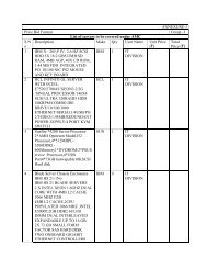
LIST OF INDICATIVE MAKES<br />
The following is the list of products and indicative makes. Bidder is free to propose any other<br />
equivalent Make meeting <strong>Technical</strong> Requirements, <strong>Specifications</strong> alongwith required details in<br />
support of the same. The same would be analyzed and accepted if found suitable after discussion<br />
between EPI and bidder. The Makes shall be finalized during <strong>Technical</strong> evaluation prior to opening of<br />
Price-Bids.<br />
Bidders are required to offer reputed equipment / component which is strictly meeting technical<br />
requirements, enclosed specifications alongwith NIT and other relevant / latest applicable Standards<br />
& Rules.<br />
S<br />
No.<br />
A.<br />
Items Indicative Make<br />
IP CCTV Surveillance<br />
System<br />
1 Cameras<br />
2 Server IBM/HP/DELL<br />
3 Software<br />
4 Media Convertor Cisco/Amp/HP<br />
B. Access Control System<br />
1<br />
Single Door Network<br />
Controller/Reader<br />
Dvtel / Axis/ Indigovision / Pelco/ Honeywell/ Smart Guard /<br />
Panasonic / Sony/Siemens<br />
Dvtel / Axis/ Indigovision / Pelco/ Honeywell/ Smart Guard /<br />
Panasonic / Sony/Siemens<br />
HID/Europlex/Spectra/Honeywell<br />
2 Electromagnetic Lock Alcate/Faraday/Honeywell/Capture<br />
3 Exit switch Reputed Make ( As per recommendation of ACS manufacturer)<br />
4 Door Contact Reputed Make ( As per recommendation of ACS manufacturer)<br />
5<br />
Software for Access Control<br />
System<br />
HID/Europlex/Spectra/Honeywell<br />
Page 28 of 30
C.<br />
Boom-Barrier and<br />
Turnstile<br />
1 Boom Barrier Came/FAAC/ Automatic Sytems/Magnetic Control<br />
2<br />
Electro-mechanical<br />
Turnstiles<br />
D. Other Items<br />
1<br />
Came/FAAC/ Automatic Sytems/Magnetic Control<br />
Cat Cable, Fiber cable and<br />
passive components Digilink /Molex/Amp/Systimax/Siemon/Panduit<br />
2 Cable & Wire Universal/Rallison/Asian/Delton/Finolex/National/Havells<br />
3 PVC conduit ISI Approved<br />
4 GI conduit ISI Approved<br />
5 UPS APC / Emerson / DB Power/ Uniline<br />
6 Battery Exide/Panasonic/HBL /Yousa/AMCO/Amaraja<br />
7 HDPE Pipe ISI Approved<br />
Note :- Items which are not mentioned in above list but required at site, shall be supplied with prior<br />
approval of purchaser.<br />
Page 29 of 30
DRAWINGS/ DOCUMENTS LIST<br />
SR. NO. DESCRIPTION DRAWING NO.<br />
01<br />
02<br />
03<br />
04<br />
LAYOUT, BUILDINGS CO-ORDINATES<br />
PLAN<br />
IPCCTV, ACCESS CONTROL SYSTEM,<br />
BOOM-BARRIER & TURNSTILE LAYOUT<br />
PLAN<br />
IP CCTV, ACCESS CONTROL SYSTEM,<br />
BOOM-BARRIER & TURNSTILE DETAIL<br />
DRAWING<br />
CONNECTIVITY OF DATA CABLE OF<br />
CCTV CAMERA & ACS TO<br />
NETWORKING SWITCHES<br />
Page 30 of 30<br />
CDRI/LKW/499/A1W-043<br />
CDRI 000 00 P 02 -00<br />
CDRI 000 00 D 03 -00<br />
CDRI/LKW/499/ACS-01