Product catalog (pdf) - Maretron
Product catalog (pdf) - Maretron
Product catalog (pdf) - Maretron
- No tags were found...

You also want an ePaper? Increase the reach of your titles
YUMPU automatically turns print PDFs into web optimized ePapers that Google loves.
PRODUCT CATALOG
www.maretron.com
Contents<br />
PRODUCT<br />
CATALOG<br />
<strong>Maretron</strong>, a world leader in vessel monitoring<br />
and control systems, designs, manufactures,<br />
and markets leading edge products for<br />
commercial and recreational marine markets.<br />
Our products are highly integrated to provide<br />
a common user interface to the equipment<br />
and systems commonly found onboard a<br />
vessel. <strong>Maretron</strong>’s corporate philosophy is to<br />
provide premium quality, state-of-the-art vessel<br />
monitoring and control products that work<br />
in conjunction with traditional navigation and<br />
monitoring techniques for the highest level of<br />
safety and performance while on the water.<br />
User Interface <strong>Product</strong>s<br />
NMEA 2000 ® Gateways and Bridges<br />
Tank Monitoring<br />
Engine Monitoring<br />
Electrical Monitoring and Control<br />
General Systems Monitoring<br />
Navigation Instruments<br />
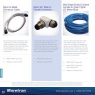
Cables and Connectors<br />
Network Installation Guide<br />
866-550-9100
World-class standards in vessel<br />
monitoring and control systems.<br />
Simpler, safer, and more secure boating.<br />
These are the guiding principles of <strong>Maretron</strong>.<br />
We understand that a vessel is made up of many complex systems including the engine, transmission,<br />
generators, electrical, and much, much more. Trying to keep track of this equipment to ensure a safe<br />
and secure journey can be overwhelming. Without the appropriate vessel monitoring and control system,<br />
small issues can quickly turn into dangerous situations, and can even become life-threatening. Further<br />
complicating the task at hand is the different user interfaces for each piece of equipment, all having<br />
various gauges, buttons, and ways to setup and acknowledge alarms.<br />
At <strong>Maretron</strong>, we have developed a single, common interface to monitor and control your vessel’s<br />
systems so you don’t have to learn and remember different ways to interact with each piece of<br />
equipment. And with a built-in comprehensive alert system, you don’t have to sit and stare at the gauges<br />
because you will get an alarm or warning at the slightest hint of a problem, before it turns into a larger,<br />
more serious issue. Look at it as your very own “second mate” or “engineer,” continuously watching<br />
over your vessel 24 hours a day, 7 days a week, 365 days a year. Additional key features include:<br />
• Safety – alarms for fire, smoke, combustible gasses,<br />
carbon monoxide and high bilge water<br />
• Security – includes cameras, motion detectors, and<br />
magnetic door and port hole sensors<br />
• Ease of use – provides one simple, common user<br />
interface for all systems<br />
• Remote monitoring and notification – includes<br />
monitoring remotely plus video, email and text notifications<br />
• Future support – easily expandable systems grow with your needs<br />
<strong>Maretron</strong>. Providing solutions for all of your<br />
vessel monitoring and control needs.<br />
www.maretron.com<br />
4
Vessel Monitoring and Control<br />
User Interface <strong>Product</strong>s<br />
(N2KView, N2KView Mobile,<br />
DSM150, DSM250, DSM800,<br />
TSM800, TSM1330, MBB100)<br />
GPS Antenna/Receiver<br />
(GPS200)<br />
Solid State Compass<br />
(SSC200)<br />
Ultrasonic Wind<br />
and Weather Station<br />
(WSO100)<br />
Electrical Control<br />
Lighting, Pumps, Etc.<br />
(DCR100)<br />
Networked Systems Benefits<br />
<strong>Maretron</strong>’s products communicate over a Controller<br />
Area Network (CAN bus) using the National Marine<br />
Electronics Association’s NMEA 2000 ® protocol. The<br />
advantages of using CAN bus are numerous and<br />
include low wiring complexity with all components<br />
interconnected through a single cabling system.<br />
The reduction in wire over conventional systems<br />
is significant resulting in lower installation and<br />
maintenance cost and lower overall vessel weight.<br />
And since the individual products are connected to<br />
drop lines from the main trunk line, a single product<br />
failure doesn’t affect communication between<br />
other devices. In addition, the CAN bus easily<br />
accommodates adding products to the network for<br />
future expansion. Probably most importantly, you<br />
are no longer constrained to viewing your vessel’s<br />
information from an independent system from a<br />
single place using a single display. With <strong>Maretron</strong>’s<br />
networked solutions, you simply place a display<br />
anywhere on the network, whether it is at the helm,<br />
in the engine room, or sleeping quarters, and you<br />
are free to monitor and control anything connected<br />
to the network from anywhere on the vessel.<br />
Shore Power<br />
Monitor<br />
(ACM100)<br />
Run Indicator<br />
Blowers, Pumps, Etc.<br />
(RIM100)<br />
Depth, Speed,<br />
Temp<br />
(DST110)<br />
Battery Monitor<br />
(DCM100)<br />
Smoke, CO, Gas, Doors,<br />
High Bilge (SIM100)<br />
Engine Room, Refrigerator,<br />
Freezer Temperatures<br />
(TMP100)<br />
Water, Waste, Oil,<br />
Fuel Tanks (FPM100,<br />
Remote Monitoring<br />
TLM100, TLM150,<br />
and Control<br />
TLM200, TLA100)<br />
Using your vessel’s Internet connection<br />
and <strong>Maretron</strong>’s Internet Protocol Gateway<br />
(IPG100), you can stay connected to your vessel from<br />
anywhere in the world. Imagine receiving an email notification<br />
indicating high bilge water or a motion sensor alarm and you simply log<br />
onto the vessel with your smart phone, tablet, or PC and start an auxiliary bilge<br />
pump or switch on a light to scare off intruders. You can even watch live video feeds from<br />
the vessel so you can keep an eye on the vessel from anywhere in the world.<br />
Generator Monitoring<br />
(J2K100, ACM100)<br />
Fuel Flow Monitor<br />
(FFM100) Engine Monitor<br />
(J2K100, EMS100)<br />
Rudder Angle Adapter<br />
(RAA100)
User Interface<br />
<strong>Product</strong>s<br />
N2KView ® - Vessel Monitoring and Control Software<br />
N2KView ® Mobile - Vessel Monitoring and Control Software<br />
TSM800 - 8” Vessel Monitoring and Control Touchscreen<br />
TSM1330 - 13.3” Vessel Monitoring and Control Touchscreen<br />
DSM800 - Vessel Monitoring and Control Indoor Display<br />
MBB100 - Black Box Vessel Monitoring and Control<br />
<strong>Maretron</strong> Cloud Services - Remote Vessel Monitoring and Control<br />
DSM150 - 3.5” High Bright Color Display<br />
DSM250 - Multi-Function Color Display<br />
ALM100 - Alarm Module<br />
If you think about all the systems onboard a vessel and what needs to be<br />
monitored to keep each person safe, secure, and comfortable, it can be a<br />
daunting task. Is there enough fuel to make it to the destination, is the engine<br />
overheating, is the bilge filling up with water, is there carbon monoxide in the<br />
sleeping quarters <strong>Maretron</strong> offers user interface products that dramatically<br />
reduce the stress associated with keeping track of all your systems. In fact,<br />
every single parameter from every system onboard can be monitored 24/7 using<br />
programmable alerts or alarms, which gives you an early warning of potential<br />
problems before they become an annoyance or even a threatening situation.<br />
Furthermore, all vessel system information is available through one highly intuitive<br />
and configurable user interface so you don’t have to learn how to operate multiple<br />
disparate systems. And all the vessel monitoring and control information is<br />
networked, so you can get the data wherever it’s needed, whether it be onboard<br />
or ashore using desktop computers, laptops, handhelds, or tablets.<br />
TSM800<br />
8” Vessel Monitoring and Control Touchscreen<br />
TSM1330<br />
13.3” Vessel Monitoring and Control Touchscreen<br />
DSM800<br />
Vessel Monitoring and Control Indoor Display<br />
6
MBB100<br />
Black Box Vessel Monitoring and Control<br />
DSM150<br />
3.5” High Bright Color Display<br />
DSM250<br />
Multi-Function Color Display<br />
ALM100<br />
Alarm Module
N2KView ®<br />
Vessel Monitoring<br />
and Control Software<br />
Whether you are interested in monitoring your<br />
vessel’s systems while underway or remotely<br />
from your home or office, <strong>Maretron</strong>’s N2KView ®<br />
software displays the information you need<br />
including engines, generators, tanks, rudders,<br />
navigation instruments, local weather, and<br />
much, much more. N2KView ® is completely<br />
user-configurable and you are free to create<br />
different screens for your exact needs while easily<br />
switching from screen to screen for monitoring<br />
all your systems. Digital displays, analog gauges,<br />
graphic displays, warning lights, and bar graphs,<br />
all can be configured exactly how you want them<br />
to be. You can even set the operating limits and<br />
color bands for analog gauges so you know when<br />
things are within limits and when they are not.<br />
N2KView ® is a comprehensive suite of software that allows<br />
you to pick and choose modules for your exact needs. You<br />
start with the base software that allows you to display any<br />
of <strong>Maretron</strong>’s vessel monitoring sensors. Once you have the<br />
N2KView ® base software you can add optional modules like the<br />
Alerts, Video, Control, and Fuel Management. Adding the alert<br />
module allows you to set as many warnings and alarms as you<br />
need so you can be forewarned of potential problems. With the<br />
alert module, you can relax knowing that the system is watching<br />
for smoke, CO, high bilge water, or anything else you deem<br />
important. The video module allows you to add cameras as part<br />
of the monitoring system - for example a camera in the engine<br />
room - or the cameras can be used as part of the security<br />
<strong>Product</strong>s<br />
PART NUMBER<br />
N2KView-Base<br />
N2KView-Add<br />
N2KView-Alerts<br />
N2KView-Video<br />
N2KView-Control<br />
N2KView-Fuel<br />
DESCRIPTION<br />
N2KView Vessel Monitoring Software with Hardware License Key<br />
N2KView (Additional N2KView License added to Existing N2KView-Base)<br />
Alerts Module (Each Alerts Module requires corresponding Base or Add License)<br />
Video Module (Each Video Module requires corresponding Base or Add License)<br />
Control Module (Each Control Module requires corresponding Base or Add License)<br />
Fuel Module (Each Fuel Module requires corresponding Base or Add License)<br />
8<br />
www.maretron.com 1-866-550-9100
system. The Control module gives you the<br />
ability to manage your electrical system; for<br />
example, you can turn lights or pumps on<br />
or off directly from N2KView ® and even tell<br />
if the lights or pumps are burned out and<br />
not working. Lastly, the Fuel Management<br />
module uses information from the fuel flow<br />
monitor, tank monitors, and GPS to provide<br />
advanced information like distance and<br />
time to empty as well as fuel rate and fuel<br />
economy.<br />
N2KView ® software can run on your vessel’s<br />
computer or on standalone products like<br />
<strong>Maretron</strong>’s DSM800 display (see page 12)<br />
or the <strong>Maretron</strong> Black Box (MBB100) vessel<br />
monitoring system (see page 18). If you<br />
want to run N2KView ® software on your<br />
vessel’s computer, you will need either a<br />
<strong>Maretron</strong> USB100 (page 30) or an IPG100<br />
(page 32), which are necessary to get<br />
sensor information from the NMEA 2000 ®<br />
network to the computer. If you want to<br />
run N2KView ® on standalone products like<br />
the DSM800 and MBB100, you will need to<br />
purchase an IPG100.<br />
Windows PC Server/Client System Requirements<br />
Parameter Value Comment<br />
Operating System Windows XP/Vista/7 and Mac OS Latest Service Pack may be Required for Support<br />
CPU Minimum<br />
Pentium ® 4 or Equivalent<br />
CPU Recommended<br />
Pentium ® 4, (3.0 GHz)<br />
Memory Minimum<br />
512 MB RAM<br />
Memory Recommended<br />
1 GB RAM<br />
Hard Drive Space 40 MB<br />
CD-ROM or DVD Drive Single Required to Load Software<br />
Video Card Minimum<br />
128 MB<br />
Video Card Recommended<br />
256 MB<br />
USB Ports Two USB Ports – 1.1 or 2.0 Compatible One Port for Software License Key, One for <strong>Maretron</strong> Gateway<br />
Ethernet Port 10BASE-T or 100BASE-TX, or 802.11a/b/g/n Only Required for Remote Monitoring<br />
Display<br />
1024x768 Resolution, 32-bit Color Video<br />
Multiple Monitor Support Dedicated Video Cards 64 MB RAM per<br />
Certification NMEA 2000® Standard Approved<br />
Navigation<br />
Tank Levels<br />
N2KView ® uses a hardware license key that<br />
is plugged directly into a computer’s USB<br />
port if you are using a USB100 or directly<br />
into the IPG100 if you are connecting<br />
standalone devices or other PC’s connected<br />
using Ethernet. The licenses are floating<br />
so it doesn’t matter where the software is<br />
running - for example, on a PC, DSM800,<br />
MBB100, smart phone, or tablet, on the<br />
boat, or remotely through the Internet, but<br />
you do need a separate license for each<br />
N2KView ® running at the same time.<br />
AC Systems<br />
Environment<br />
DC Systems<br />
Engines<br />
Copyright 2012 <strong>Maretron</strong>, LLP. All rights reserved. As <strong>Maretron</strong> is constantly improving its products, all specifications are subject to change without notice. <strong>Maretron</strong>’s products are designed to<br />
be accurate and reliable; however, they should be used only as aids to navigation and vessel monitoring, and not as a replacement for traditional navigation and vessel monitoring techniques. A<br />
prudent captain or navigator never relies on a single source for navigation or system monitoring information. “NMEA 2000” is a registered trademark of the National Marine Electronics Association. 9
N2KView ® Mobile<br />
<strong>Maretron</strong>’s N2KView ® Mobile software allows you to<br />
monitor and control your vessel’s systems from your<br />
smart phone or tablet device. This includes Android<br />
(2.2 and higher) smart phones and tablets as well as<br />
Apple iPod, iPhone, and iPad. Whether it’s onboard via<br />
WiFi or ashore via an Internet connection, you can see<br />
what is happening aboard your vessel and even control<br />
things like your air conditioner, watermaker, lights,<br />
pumps, and more.<br />
What makes N2KView ® Mobile so diverse is its ability<br />
to configure your own screens. You have complete<br />
control of the number of screens, the layout of each<br />
screen, and the size and type of each parameter you<br />
wish to display. You customize each display exactly the<br />
way you want it. You use N2KView ® on a computer to<br />
design the screens, and then download them to your<br />
smart phone or tablet device.<br />
N2KView ® may be downloaded free of charge directly<br />
from the Android Market to your Android device or<br />
directly to an Apple device from the iTunes store.<br />
Although the applications are free downloads, you will<br />
need an N2KView ® license to access the vessel. Please<br />
see N2KView ® (page 8) for a description of the optional<br />
software modules and a description of the hardware<br />
license keys.<br />
<strong>Product</strong>s<br />
PART NUMBER<br />
N2KView Mobile Android<br />
N2KView Mobile Apple<br />
DESCRIPTION<br />
Free Download from Android Market<br />
Free Download from iTunes Store<br />
10<br />
www.maretron.com 1-866-550-9100
N2KView ® Mobile for Apple iPod, iPhone, iPad<br />
Parameter Value Comment<br />
iPod Touch, 3rd or 4th Generation<br />
iPod Touch, 32 or 64GB, 2nd generation N2KView Mobile version 3.2 is still available for 2nd generation iPods<br />
Hardware<br />
iPhone 3G-S, iPhone 4 or later<br />
iPad, iPad 2<br />
iOS 4.0 or later<br />
Operating System<br />
iOS 3.0 or later N2KView Mobile version 3.2 is still available for devices running iOS 3.x<br />
14.6 Mbytes for version 3.2<br />
Image Size<br />
15.8 Mbytes for version 3.3.11<br />
Screen Orientations<br />
Portrait<br />
Connection to N2KServer Encrypted using SSL encryption<br />
N2KView ® Mobile for Android<br />
Parameter Value Comment<br />
Hardware<br />
Any smart phone or tablet running the<br />
Android operating system.<br />
Operating System<br />
Android Version 2.2 (Froyo) or later<br />
Run Time Adobe Integrated Runtime (AIR) 2.6 or later Must be downloaded separately from the Android Market<br />
Image Size<br />
2.1 MBytes<br />
Screen Orientations<br />
Portrait<br />
Connection to N2KServer<br />
Encrypted using SSL encryption<br />
Copyright 2012 <strong>Maretron</strong>, LLP. All rights reserved. As <strong>Maretron</strong> is constantly improving its products, all specifications are subject to change without notice. <strong>Maretron</strong>’s products are designed to<br />
be accurate and reliable; however, they should be used only as aids to navigation and vessel monitoring, and not as a replacement for traditional navigation and vessel monitoring techniques. A<br />
prudent captain or navigator never relies on a single source for navigation or system monitoring information. “NMEA 2000” is a registered trademark of the National Marine Electronics Association. 11
DSM800<br />
Vessel Monitoring and<br />
Control Indoor Display<br />
The DSM800 is a dedicated touch screen that comes<br />
preloaded with <strong>Maretron</strong>’s N2KView ® vessel monitoring<br />
and control software. The N2KView ® software allows you<br />
to configure as many favorite screens as you want with<br />
exactly the information you want to see. Although not<br />
suitable for outdoor applications, the DSM800 provides<br />
an extremely simple touch interface for observing and<br />
controlling critical systems from inside the vessel.<br />
The DSM800 is ruggedized for marine use and includes<br />
a solid state disk drive to withstand the pounding<br />
associated with waves. And since the DSM800 only<br />
dissipates 25 watts, there is no need for internal cooling<br />
fans that are noisy and wear out causing electronics to<br />
overheat and fail.<br />
As an alternative to controlling the DSM800 through the<br />
touch screen, the DSM800 includes two USB ports for<br />
connecting keyboards, mice, or trackballs. The DSM800<br />
also has an Ethernet port for communicating with an<br />
NMEA 2000 ® network through <strong>Maretron</strong>’s Internet<br />
Protocol Gateway (IPG100). Although the DSM800<br />
comes pre-installed with the N2KView ® software, a<br />
separately purchased license plugged into the IPG100<br />
is required (see IPG100 on page 32 for more details).<br />
The Ethernet port is also used for connecting Internet<br />
Protocol (IP) cameras for viewing within the N2KView ®<br />
software.<br />
DSM800 features:<br />
• 8” LED Backlit LCD Panel with Resistive Touch Screen<br />
• 800 x 600 Pixels<br />
• 250 nits of brightness<br />
• Solid State Disk Drive<br />
• Fanless cooling system<br />
<strong>Product</strong>s<br />
PART NUMBER<br />
DSM800-01<br />
DC/DC-01<br />
MAFLPK-12<br />
MAFLWK-12<br />
DESCRIPTION<br />
Vessel Monitoring and Control Indoor Display<br />
DC/DC Conv. 9039VDC In 12VDC Out 60W<br />
DSM800 Panel Mounting Kit<br />
DSM800 Wall Mounting Kit<br />
12<br />
www.maretron.com 1-866-550-9100
Environmental Mechanical Electrical Approvals Specifications<br />
Parameter Value Comment<br />
Display Size 8” LED Backlit LCD with Resistive Touch Screen<br />
Display Resolution 800x600 Pixel count<br />
Display Brightness<br />
250cd/m2<br />
Contrast Ratio 400:1<br />
LCD Color<br />
262K<br />
Viewing Angle<br />
130° H 120° V<br />
Backlight MTBF<br />
30,000 hours<br />
USB Ports Two USB 2.0<br />
Ethernet Ports<br />
One GbE<br />
Audio<br />
One Speaker Output<br />
Parameter<br />
FCC,CE, CB, CCC<br />
Parameter Value Comment<br />
Operating Voltage 12 Volts DC Voltage<br />
Power Consumption (Maximum)<br />
25 Watts<br />
Parameter Value Comment<br />
Overall Dimensions (DxWxH)<br />
1.69” x 9.21” x 6.97”<br />
(43mm x 234mm x 177mm)<br />
Weight<br />
Front Panel Material<br />
1.76 lbs (.8kg)<br />
ABS Plastic<br />
Comment<br />
Mounting Wall, Rack, Stand, ARM, VESA, 75mm x 75mm<br />
Parameter<br />
Value<br />
Operating Temperature -10°C to 50°C<br />
Storage Temperature -10°C to 60°C<br />
DSM800 Screen Shots<br />
Copyright 2012 <strong>Maretron</strong>, LLP. All rights reserved. As <strong>Maretron</strong> is constantly improving its products, all specifications are subject to change without notice. <strong>Maretron</strong>’s products are designed to<br />
be accurate and reliable; however, they should be used only as aids to navigation and vessel monitoring, and not as a replacement for traditional navigation and vessel monitoring techniques. A<br />
prudent captain or navigator never relies on a single source for navigation or system monitoring information. “NMEA 2000” is a registered trademark of the National Marine Electronics Association. 13
TSM800<br />
8” Vessel Monitoring and Control<br />
Touchscreen<br />
The TSM800 is an 8” dedicated touchscreen that comes<br />
preloaded with <strong>Maretron</strong>’s N2KView ® vessel monitoring<br />
and control software. The N2KView ® software allows<br />
you to configure as many favorite screens as you<br />
want with exactly the information you want to see. The<br />
TSM800 provides an extremely simple touch interface<br />
for monitoring and controlling critical systems from<br />
anywhere on the vessel.<br />
The TSM800 is ruggedized for marine use and includes<br />
a solid state disk drive to withstand the pounding<br />
associated with waves. And since the TSM800 only<br />
dissipates 20 watts, there is no need for internal cooling<br />
fans that are noisy and wear out causing electronics to<br />
overheat and fail. The TSM800 can be mounted outside<br />
given the high bright screen and waterproof front.<br />
As an alternative to controlling the TSM800 through the<br />
touch screen, the TSM800 includes two USB ports for<br />
connecting keyboards, mice, or trackballs. The TSM800<br />
also has an Ethernet port for communicating with an<br />
NMEA 2000 ® network through <strong>Maretron</strong>’s Internet<br />
Protocol Gateway (IPG100). Although the TSM800 comes<br />
pre-installed with the N2KView ® software, a separately<br />
purchased license plugged into the IPG100 is required<br />
(see IPG100 on page 32 for more details). The Ethernet<br />
port is also used for connecting Internet Protocol (IP)<br />
cameras for viewing within the N2KView ® software.<br />
TSM800 features:<br />
• 8” TFT LCD Panel, LED Backlit<br />
• Widescreen Aspect Ratio 5:3<br />
• 800 x 480 Pixels<br />
• 600 nits Brightness (Optically Bonded)<br />
• Solid State Disk Drive<br />
• Fanless Cooling System<br />
• Flush Mounting Hardware Included<br />
• Optional VESA Mounting Capability<br />
<strong>Product</strong>s<br />
PART NUMBER<br />
TSM800-01<br />
DESCRIPTION<br />
8” Vessel Monitoring and Control Touchscreen<br />
14<br />
www.maretron.com 1-866-550-9100
Optional<br />
USB Keyboard<br />
Or Mouse<br />
Engine<br />
Monitor<br />
Battery<br />
Monitor<br />
236mm <br />
9.29” <br />
TSM800<br />
Electrical<br />
Panel<br />
TSM800 <br />
Tank<br />
Monitor<br />
166mm <br />
6.54” <br />
45mm <br />
1.77” <br />
Ethernet<br />
<strong>Maretron</strong><br />
IPG100<br />
51mm <br />
2.01” <br />
NMEA 2000<br />
Network<br />
Environmental Mechanical Electrical Hardware Approvals Specifications<br />
Parameter Value Comment<br />
Display Size 8” LED Backlit LCD with Projected Capacitive Touch Screen<br />
Display Resolution 800x480 WVGA<br />
Display Brightness 600cd/m2 Optically Bonded<br />
Contrast Ratio 600:1<br />
LCD Color<br />
262K<br />
Viewing Angle<br />
70° H, 60° V<br />
Buzzer 85dB IEC 60945 Compliant<br />
USB Ports Two USB 2.0<br />
Ethernet Ports One RJ-45 GbE For connection to <strong>Maretron</strong> IPG100 or router<br />
Parameter<br />
IEC 60945<br />
GL – Germanischer Lloyd<br />
BV –Bureau Veritas<br />
IACS E10<br />
DNV - Det Norske Veritas<br />
LRS – Lloyd’s Register of Shipping<br />
ClassNK – Nippon Kaiji Kyoaki<br />
ABS – American Bureau of Shipping<br />
Parameter Value Comment<br />
Operating Voltage 18-32 Volts DC Voltage, Dual Inputs<br />
Power Consumption<br />
20 Watts Typical<br />
30 Watts Maximum<br />
Parameter Value Comment<br />
Overall Dimensions (DxWxH)<br />
2.01” x 9.29” x 6.54”<br />
(51mm x 236mm x 166mm)<br />
Weight<br />
4.2 lbs (1.9kg)<br />
Front Panel Material<br />
Glass<br />
Front Panel Controls Power, Brightness +/-<br />
Mounting<br />
4 x M4 VESA mounting 75mm x 75mm Max 8mm deep<br />
Built-in console Mounting<br />
4 x M5 x 15mm screws<br />
Parameter<br />
Value<br />
Operating Temperature -15°C to 55°C (Humidity up to 95%)<br />
Storage Temperature -20°C to 60°C (Humidity up to 95%)<br />
IP Rating<br />
IP66 Front, IP22 Rear (EN60529)<br />
Comment<br />
TSM800 Screen Shots<br />
Copyright 2012 <strong>Maretron</strong>, LLP. All rights reserved. As <strong>Maretron</strong> is constantly improving its products, all specifications are subject to change without notice. <strong>Maretron</strong>’s products are designed to<br />
be accurate and reliable; however, they should be used only as aids to navigation and vessel monitoring, and not as a replacement for traditional navigation and vessel monitoring techniques. A<br />
prudent captain or navigator never relies on a single source for navigation or system monitoring information. “NMEA 2000” is a registered trademark of the National Marine Electronics Association. 15
TSM1330<br />
13.3” Vessel Monitoring<br />
and Control Touchscreen<br />
The TSM1330 is an 13.3” dedicated touchscreen that<br />
comes preloaded with <strong>Maretron</strong>’s N2KView ® vessel<br />
monitoring and control software. The N2KView ® software<br />
allows you to configure as many favorite screens as you<br />
want with exactly the information you want to see. The<br />
TSM1330 provides an extremely simple touch interface<br />
for monitoring and controlling critical systems from<br />
anywhere on the vessel.<br />
The TSM1330 is ruggedized for marine use and includes<br />
a solid state disk drive to withstand the pounding<br />
associated with waves. And since the TSM1330 only<br />
dissipates 20 watts, there is no need for internal cooling<br />
fans that are noisy and wear out causing electronics to<br />
overheat and fail. The TSM1330 can be mounted outside<br />
given the high bright screen and waterproof front.<br />
As an alternative to controlling the TSM1330 through the<br />
touch screen, the TSM1330 includes two USB ports for<br />
connecting keyboards, mice, or trackballs. The TSM1330<br />
also has an Ethernet port for communicating with an<br />
NMEA 2000 ® network through <strong>Maretron</strong>’s Internet<br />
Protocol Gateway (IPG100). Although the TSM1330<br />
comes pre-installed with the N2KView ® software, a<br />
separately purchased license plugged into the IPG100<br />
is required (see IPG100 on page 32 for more details).<br />
The Ethernet port is also used for connecting Internet<br />
Protocol (IP) cameras for viewing within the N2KView ®<br />
software.<br />
<strong>Product</strong>s<br />
PART NUMBER<br />
DESCRIPTION<br />
TSM1330 features:<br />
• 13.3” TFT LCD Panel, CCFL Backlit<br />
• Widescreen Aspect Ratio 16:10<br />
• 1280 x 800 Pixels<br />
• 400 nits Brightness (Optically Bonded)<br />
• Solid State Disk Drive<br />
• Fanless Cooling System<br />
• Flush Mounting Hardware Included<br />
• Optional VESA Mounting Capability<br />
TSM1330-01<br />
13.3” Vessel Monitoring and Control Touchscreen<br />
16<br />
www.maretron.com 1-866-550-9100
Optional<br />
USB Keyboard<br />
Or Mouse<br />
Engine<br />
Monitor<br />
Battery<br />
Monitor<br />
355mm <br />
13.98” <br />
TSM1330<br />
Electrical<br />
Panel<br />
Tank<br />
Monitor<br />
TSM1330 <br />
248.5mm <br />
9.78” <br />
52mm <br />
2.05” <br />
Ethernet<br />
<strong>Maretron</strong><br />
IPG100<br />
NMEA 2000<br />
Network<br />
58mm <br />
2.28” <br />
Environmental Mechanical Electrical Hardware Approvals Specifications<br />
Parameter Value Comment<br />
Display Size 13.3” CCFL Backlit LCD with Projected Capacitive Touch Screen<br />
Display Resolution 1280x800 WXGA<br />
Display Brightness 400cd/m2 Optically Bonded<br />
Contrast Ratio 800:1<br />
LCD Color<br />
262K<br />
Viewing Angle<br />
70° H, 60° V<br />
Buzzer 85dB IEC 60945 Compliant<br />
USB Ports Two USB 2.0<br />
Ethernet Ports One RJ-45 GbE For connection to <strong>Maretron</strong> IPG100 or router<br />
Parameter<br />
IEC 60945<br />
GL – Germanischer Lloyd<br />
BV – Bureau Veritas<br />
IACS E10<br />
DNV – Det Norske Veritas<br />
LRS – Lloyd’s Register of Shipping<br />
ClassNK – Nippon Kaiji Kyoaki<br />
ABS – American Bureau of Shipping<br />
Parameter Value Comment<br />
Operating Voltage 18-32 Volts DC Voltag, Dual Inputs<br />
Power Consumption<br />
20 Watts Typical<br />
30 Watts Maximum<br />
Parameter Value Comment<br />
Overall Dimensions (DxWxH)<br />
2.28” x 13.98” x 9.78”<br />
(58mm x 355mm x 248.5mm)<br />
Weight<br />
9.7 lbs (4.4kg)<br />
Front Panel Material<br />
Glass<br />
Front Panel Controls Power, Brightness +/-<br />
Mounting<br />
4 x M4 VESA mounting 75mm x 75mm Max 8mm deep<br />
Built-in console Mounting<br />
4 x M5 x 15mm screws<br />
Parameter<br />
Value<br />
Operating Temperature -15°C to 55°C (Humidity up to 95%)<br />
Storage Temperature -20°C to 60°C (Humidity up to 95%)<br />
IP Rating<br />
IP66 Front, IP22 Rear (EN60529)<br />
Comment<br />
TSM1330 Screen Shots<br />
Copyright 2012 <strong>Maretron</strong>, LLP. All rights reserved. As <strong>Maretron</strong> is constantly improving its products, all specifications are subject to change without notice. <strong>Maretron</strong>’s products are designed to<br />
be accurate and reliable; however, they should be used only as aids to navigation and vessel monitoring, and not as a replacement for traditional navigation and vessel monitoring techniques. A<br />
prudent captain or navigator never relies on a single source for navigation or system monitoring information. “NMEA 2000” is a registered trademark of the National Marine Electronics Association. 17
MBB100<br />
Black Box Vessel<br />
Monitoring and Control<br />
<strong>Maretron</strong>’s Black Box (MBB100) is a dedicated<br />
processing unit that comes preloaded with <strong>Maretron</strong>’s<br />
N2KView ® vessel monitoring and control software.<br />
Unlike a PC that allows any software to be loaded,<br />
the MBB100 runs only N2KView ® software making<br />
it extremely stable and dedicated to monitoring and<br />
controlling your vessel.<br />
The MBB100 is ruggedized for marine use and includes<br />
a solid state disk drive to withstand the pounding<br />
associated with waves. And since the MBB100<br />
dissipates less than 20 watts, there is no need for<br />
internal cooling fans that are noisy and wear out<br />
causing electronics to overheat and fail.<br />
The MBB100 connects to a monitor through a VGA<br />
connector and associated touch screen through a USB<br />
or serial port connection. Alternatives to controlling<br />
the N2KView ® software through a touch screen<br />
include keyboards, mice, or track balls connected<br />
through USB. The MBB100 has an Ethernet port for<br />
communicating with an NMEA 2000 ® network through<br />
<strong>Maretron</strong>’s Internet Protocol Gateway (IPG100).<br />
Although the MBB100 comes pre-installed with the<br />
N2KView ® software, a separately purchased license<br />
plugged into the IPG100 is required (see IPG100 on<br />
page 32 for more details). The Ethernet port is also<br />
used for connecting Internet Protocol (IP) cameras for<br />
viewing within the N2KView ® software.<br />
Of course you get the same flexibility using <strong>Maretron</strong>’s<br />
N2KView ® software from the MBB100 as you would<br />
running the software on a PC, which includes the ability<br />
to configure as many screens as you want with exactly<br />
the information you want to see. Plus you get free<br />
upgrades to the software as improvements and new<br />
features are added.<br />
<strong>Product</strong>s<br />
PART NUMBER<br />
MBB100-01<br />
DESCRIPTION<br />
Black Box Vessel Monitoring and Control<br />
18<br />
www.maretron.com 1-866-550-9100
MBB100<br />
132<br />
!<br />
Environmental Mechanical Electrical Certifications Specifications<br />
Parameter Value Comment<br />
Video Connector<br />
One VGA Port (RGB<br />
For Monitor Connection<br />
or D-sub 15)<br />
USB Connector<br />
Serial Connector<br />
Four USB 2.0<br />
connections<br />
One RS232 9-Pin D<br />
Connector<br />
For connecting Peripherals (Mouse, keyboard, etc.) and or<br />
touch screen connectivity<br />
For touch screen alternative connection<br />
Ethernet Connector Two GbE For connection to <strong>Maretron</strong> IPG100 Gateway or/and router<br />
Audio Connection<br />
One Speaker Output<br />
FCC class A and CE Mark<br />
Parameter Value Comment<br />
Operating Voltage 9 to 36 Volts DC Voltage<br />
Power Consumption (Maximum)<br />
19 Watts<br />
Parameter Value Comment<br />
Overall Dimensions (DxWxH)<br />
5.19” x 9.02” x 2.52”<br />
(132mm x 229mm x 64mm)<br />
Including Flanges for Mounting<br />
Weight<br />
Chassis Material<br />
Parameter<br />
4.6 lbs (2.1kg)<br />
Aluminum<br />
Mounting Vesa 100 or DIN Any Orientation<br />
Comment<br />
Electromagnetic Compatibility<br />
Parameter<br />
Value<br />
Operating Temperature -10°C to 60°C<br />
Operating Shock<br />
Half-sine wave shock 3G; 11 ms; 3 shocks per axis<br />
Vibration<br />
MIL-STD-810F 514.5C-2<br />
Copyright 2012 <strong>Maretron</strong>, LLP. All rights reserved. As <strong>Maretron</strong> is constantly improving its products, all specifications are subject to change without notice. <strong>Maretron</strong>’s products are designed to<br />
be accurate and reliable; however, they should be used only as aids to navigation and vessel monitoring, and not as a replacement for traditional navigation and vessel monitoring techniques. A<br />
prudent captain or navigator never relies on a single source for navigation or system monitoring information. “NMEA 2000” is a registered trademark of the National Marine Electronics Association. 19
<strong>Maretron</strong> Cloud Services<br />
<strong>Maretron</strong> Cloud Services allows you to<br />
remotely and seamlessly connect to your<br />
vessel using N2KView ® or N2KView ® Mobile<br />
software so you can monitor and control<br />
your vessel from anywhere in the world.<br />
As long as there is an Internet connection<br />
to the vessel, <strong>Maretron</strong>’s Internet Protocol<br />
Gateway (IPG100) will automatically log into<br />
<strong>Maretron</strong>’s Internet cloud server and the<br />
vessel’s information will be made available to<br />
any remote N2KView ® or N2KView ® Mobile.<br />
Connection between your vessel and remote<br />
N2KView ® software has never been easier,<br />
whether your vessel’s Internet connection is<br />
via a marina WiFi, satellite connection, GSM<br />
or cell phone modem, or any other type of<br />
Internet connection, you’ll have access to the<br />
vessel from anywhere in the world.<br />
<strong>Product</strong>s<br />
PART NUMBER<br />
MCS-25GB<br />
MCS-50GB<br />
MCS-100GB<br />
DESCRIPTION<br />
Remote Vessel Monitoring & Control Data Plan (1 Year Contract Required-25GB/month)<br />
Remote Vessel Monitoring & Control Data Plan (1 Year Contract Required-50GB/month)<br />
Remote Vessel Monitoring & Control Data Plan (1 Year Contract Required-100GB/month)<br />
Using <strong>Maretron</strong> Cloud Services is simple, just<br />
imagine receiving an email or text notification from<br />
the vessel indicating a problem and you simply log<br />
onto the vessel using a smart phone, tablet, or PC.<br />
Using <strong>Maretron</strong>’s N2KView ® vessel monitoring and<br />
control software you get a better understanding of the<br />
problem and you can even initiate a corrective action<br />
like resetting tripped breakers, turning on auxiliary<br />
pumps or lights. Or maybe you just want to adjust<br />
the air conditioner or start the ice maker on your way<br />
to the boat. Whatever the reason, <strong>Maretron</strong> Cloud<br />
Services provides you with a seamless connection to<br />
your vessel for peace of mind and convenient access<br />
from anywhere in the world.<br />
20<br />
www.maretron.com 1-866-550-9100
Multiple Wired and<br />
Wireless Devices<br />
Running N2KView ®<br />
Software<br />
Remote Wired and<br />
Wireless Devices<br />
Running N2KView ®<br />
Software<br />
Laptop or<br />
Desktop<br />
Smartphone<br />
Tablet<br />
Via<br />
Wi-Fi<br />
Tablet<br />
USB / RS232<br />
Engine<br />
Monitor<br />
VGA Monitor<br />
With Touch<br />
Screen<br />
<strong>Maretron</strong><br />
MBB100<br />
Battery<br />
Monitor<br />
<strong>Maretron</strong><br />
IPG100<br />
Electrical<br />
Panel<br />
VGA<br />
<strong>Maretron</strong><br />
DSM800<br />
Ethernet<br />
Tank<br />
Monitor<br />
Wi-Fi / Router<br />
Ethernet<br />
Video Encoder<br />
NMEA 2000 ®<br />
Network<br />
Internet<br />
Connection<br />
(GSM, Satellite,<br />
DSL, Cable)<br />
Analog/IP<br />
Cameras<br />
Ship<br />
<strong>Maretron</strong><br />
Cloud<br />
Services<br />
Internet<br />
Shore<br />
Smartphone<br />
Laptop or<br />
Desktop<br />
Copyright 2012 <strong>Maretron</strong>, LLP. All rights reserved. As <strong>Maretron</strong> is constantly improving its products, all specifications are subject to change without notice. <strong>Maretron</strong>’s products are designed to<br />
be accurate and reliable; however, they should be used only as aids to navigation and vessel monitoring, and not as a replacement for traditional navigation and vessel monitoring techniques. A<br />
prudent captain or navigator never relies on a single source for navigation or system monitoring information. “NMEA 2000” is a registered trademark of the National Marine Electronics Association. 21
DSM150<br />
3.5” High Bright<br />
Color Display<br />
<strong>Maretron</strong>’s DSM150 is a 3.5” high-resolution sunlight<br />
viewable color display that interprets and displays NMEA<br />
2000 ® instrument, navigation, and vessel monitoring data.<br />
The DSM150 is a user friendly dedicated marine display<br />
with custom screen configurations and an easy-to-use<br />
five-key illuminated keypad. In addition to the monitoring<br />
and display capabilities, the DSM150 features an alert/<br />
alarm package and electrical switching capability.<br />
Unlike traditional single-display units, DSM150 users can<br />
choose numeric, gauge, bar or graph formats in single<br />
or multiple displays, with cycling options possible for a<br />
wide range of favorite data. These multiple display options<br />
conserve mounting space and reduce overall system cost.<br />
The DSM150 will directly connect with any NMEA 2000 ®<br />
network and with the exception of AIS data will display<br />
any or all information captured throughout the vessel.<br />
Various audio and visual alarms are also programmable.<br />
The DSM150 displays a multitude of information including<br />
AC power, anchor status, battery, depth, electrical<br />
distribution, engine, environment, fuel management,<br />
GPS, heading, navigation, pressure/vacuum, rudder,<br />
speed, status indicators, tanks, temperature, time,<br />
transmission, water makers, weather, wind and more.<br />
<strong>Maretron</strong>’s DSM150 is engineered and manufactured to<br />
the highest standards (IEC 60945 Maritime Navigation<br />
and Radiocommunication Equipment). Its compact<br />
waterproof housing will provide years of reliable<br />
performance. The DSM150 is available in a gray<br />
enclosure and includes a white sun cover and a one<br />
meter NMEA 2000 ® cable.<br />
<strong>Product</strong>s<br />
PART NUMBER<br />
DSM150-02<br />
DSM150CVR-03<br />
DSM150CABLE-01.0<br />
DESCRIPTION<br />
3.5” High Bright Color Display (Gray Enclosure)<br />
White DSM150 Cover<br />
DSM150 NMEA 2000 ® 1.0m Cable<br />
22<br />
www.maretron.com 1-866-550-9100
Parameter Value Comment<br />
70mm<br />
2.76”<br />
M4 Threaded Inserts<br />
(4X)<br />
70mm<br />
2.76”<br />
95mm<br />
3.74”<br />
95mm<br />
3.74”<br />
DSM150 Screen Shots<br />
23mm<br />
0.90”<br />
51mm<br />
2.00”<br />
23mm<br />
0.90”<br />
Copyright 2012 <strong>Maretron</strong>, LLP. All rights reserved. As <strong>Maretron</strong> is constantly<br />
improving its products, all specifications are subject to change without notice.<br />
<strong>Maretron</strong>’s products are designed to be accurate and reliable; however, they<br />
should be used only as aids to navigation and vessel monitoring, and not as<br />
a replacement for traditional navigation and vessel monitoring techniques. A<br />
prudent captain or navigator never relies on a single source for navigation or<br />
system monitoring information. “NMEA 2000” is a registered trademark of the<br />
National Marine Electronics Association.<br />
Environmental Mechanical Electrical Supported Data Display Types Certifications Specifications<br />
NMEA 2000 ® Connector DeviceNet Micro-C With Included Adapter<br />
Display Technology Active Matrix TFT LCD Sunlight Readable<br />
Display Resolution 320 x 240 Pixels QVGA Resolution<br />
Display Viewable Area 70.07mm W x 52.56mm H 3.5” Diagonal<br />
Display Brightness 800 NIT (cd/m 2 )<br />
Display Backlighting LED 3 User-Programmed Levels 0-100%<br />
Keyboard 5 Silicone Rubber Keys LED Backlighting<br />
Languages Supported English, Dutch (Nederlands) User Selectable<br />
Standard<br />
Comment<br />
NMEA 2000 ® Standard<br />
Level A<br />
Maritime Navigation and Radiocommunication Equipment & Systems IEC 61162-3<br />
Maritime Navigation and Radiocommunication Equipment & Systems IEC 60945<br />
FCC and CE Mark<br />
Electromagnetic Compatibility<br />
Instrument Type<br />
Data Types<br />
Average Frequency, Average L-N Voltage, Average L-L Voltage, Phase A Frequency, Phase A L-N Voltage,<br />
AC Power<br />
Phase AB L-L Voltage, Phase B Frequency, Phase B L-N Voltage, Phase BC L-L Voltage, Phase C<br />
Frequency, Phase C L-N Voltage, Phase CA L-L Voltage,<br />
Anchor<br />
Watch<br />
DC<br />
Current, Voltage, Battery Temperature, Battery State of Charge, Battery Time Remaining, Ripple Voltage, Power<br />
Depth<br />
Water Depth, Water Below Transducer, Transducer Offset<br />
Elec. Distribution Switch/Breaker, Breaker Current<br />
Engine Monitor<br />
Boost Pressure, Hours, Coolant Pressure, Coolant Temp., Exhaust Gas Temp., Fuel Pressure, Fuel Rate, Oil Pressure, Oil<br />
Temp., Tachometer, Tilt/Trim, Voltage, Fuel Economy, Fuel Consumption, Percent Load, Percent Torque, Trip Fuel Used,<br />
Environment<br />
Barometer, Heat Index, Humidity Inside, Humidity Outside, Moon Phase, Sunrise, Sunset, Dew Point, Temp. Engine<br />
Room, Temp. Inside, Temp. Main Cabin, Temp. Outside, Temp. Sea, Twilight AM, Twilight PM, Weather, Wind Chill<br />
Fuel Management<br />
Distance to Empty, Time to Empty, Total Fuel Capacity, Total Fuel Level, Total Fuel Consumption, Total<br />
Trip Fuel Used, Total Fuel Economy, Total Fuel Rate, Total Fuel Remaining<br />
GPS<br />
COG, Lat/Lon, SOG, DOP, Satellites, Time, Accuracy<br />
Heading<br />
Heading, Rate of Turn, Variation<br />
Humidity<br />
Inside, Outside, User Defined<br />
Indicator<br />
Status<br />
Navigation<br />
BOD, BTW, COG, XTE, DTW, ETA, Lat/Lon, Rolling Road, Set/Drift, SOG, TTG, VMG, Waypoint Number & Name<br />
Pressure/Vacuum<br />
Water, Barometric, Compressed Air, Engine Boost, Engine Coolant, Engine Fuel, Engine Oil, Hydraulic Oil,<br />
Steam, Transmission Oil, User Defined<br />
Rudder<br />
Angle & Order<br />
Speed<br />
Through Water, Over Ground, Total Log, Trip Log<br />
Tanks<br />
Capacity, Level, Remaining<br />
Temperature<br />
Wind Chill, Bait Well, Battery, Engine Coolant, Engine Oil, Engine Room, Exhaust Gas, Freezer, Heat Index,<br />
Heating System, Inside, Live Well, Main Cabin, Outside, Refrigeration, Sea, Transmission Oil, User Defined<br />
Time<br />
Local Date, UTC Date, Moon Phase, Sunrise, Sunset, Local Time, UTC Time, Twilight AM, Twilight PM<br />
Transmission Gear, Oil Pressure, Oil Temperature<br />
Vessel<br />
Pitch, Roll, Trim Tabs, Keel<br />
Watermaker<br />
Sea Recovery Status Display<br />
Wind<br />
Apparent Direction and Speed, True Direction and Speed, Ground Direction and Speed<br />
Parameter Value Comment<br />
Operating Voltage 8 to 32 Volts DC Voltage<br />
Power Consumption (Maximum)<br />
150mA<br />
Load Equivalence Number (LEN) 3 NMEA 2000® Spec. (1LEN = 50 mA)<br />
Reverse Battery Protection Yes Indefinitely<br />
Load Dump Protection Yes Energy Rated per SAE J1113<br />
Parameter Value Comment<br />
Size<br />
3.72” (H) x 3.72” (W) x 0.9” (Forward D) x 0.9” (Rear D)<br />
95mm (H) x 95mm (W) x 23mm (Forward D) x 23mm (Rear D)<br />
Weight 5.6 oz. (160 g)<br />
Mounting<br />
Flush Mount<br />
Parameter<br />
Value<br />
IEC 60945 Classification<br />
Exposed<br />
Degree of Protection<br />
IP67<br />
Operating Temperature -20°C to 70°C<br />
Storage Temperature -30°C to 80°C<br />
Relative Humidity<br />
93%RH @40° per IEC60945-8.2<br />
Vibration 2-13.2Hz @ ±1mm, 13.2-100Hz @ 7m/s 2 per IEC 60945-8.7<br />
Rain and Spray 12.5mm Nozzle @ 100liters/min from 3m for 30min per IEC 60945-8.8<br />
Solar Radiation Ultraviolet B, A, Visible, and Infrared per IEC 60945-8.10<br />
Corrosion (Salt Mist) 4 times 7 days @ 40°C, 95%RH after 2 hour Salt Spray Per IEC 60945-8.12<br />
Electromagnetic Emission<br />
Conducted and Radiated Emission per IEC60945-9<br />
Electromagnetic Immunity Conducted, Radiated, Supply, and ESD per IEC 60945-10<br />
Safety Precautions Dangerous Voltage, Electromagnetic Radio Frequency per IEC 60945-12
DSM250 Multi-Function<br />
Color Display<br />
<strong>Maretron</strong>’s DSM250 is a high-resolution sunlight<br />
viewable color display that interprets and displays<br />
NMEA 2000® instrument, navigation, and vessel<br />
monitoring data. The DSM250 is a user friendly<br />
dedicated marine display with custom screen<br />
configurations and an easy-to-use five-key<br />
illuminated keypad. In addition to the monitoring and<br />
display capabilities, the DSM250 features an alert/<br />
alarm package and electrical switching capability.<br />
Unlike traditional single-display units, DSM250 users<br />
can choose numeric, gauge, bar or graph formats<br />
in single or multiple displays, with cycling options<br />
possible for a wide range of favorite data. These<br />
multiple display options conserve mounting space<br />
and reduce overall system cost.<br />
The DSM250 will directly connect with any NMEA<br />
2000 ® network and with the exception of AIS<br />
data will display any or all information captured<br />
throughout the vessel. Various audio and visual<br />
alarms are also programmable.<br />
The DSM250 displays a multitude of information<br />
including AC power, anchor status, battery, depth,<br />
electrical distribution, engine, environment, fuel<br />
management, GPS, heading, navigation, pressure/<br />
vacuum, rudder, speed, status indicators, tanks,<br />
temperature, time, transmission, water makers,<br />
weather, wind and more.<br />
<strong>Maretron</strong>’s DSM250 is engineered and manufactured<br />
to the highest standards (IEC 60945 Maritime<br />
Navigation and Radiocommunication Equipment).<br />
Its compact waterproof housing will provide years<br />
of reliable performance. The DSM250 is available in<br />
three different color cases: black, gray, or white.<br />
<strong>Product</strong>s<br />
PART NUMBER<br />
DSM250-01<br />
DSM250-02<br />
DSM250-03<br />
DSMMNTASSBLY<br />
DSM250CVR2PK-01<br />
DSM250CVR2PK-02<br />
DSM250CVR2PK-03<br />
DESCRIPTION<br />
High Bright Color Display (Black Enclosure)<br />
High Bright Color Display (Gray Enclosure)<br />
High Bright Color Display (White Enclosure)<br />
DSM200/DSM250 Gimbal Mount<br />
Package of (2) Black DSM250 Covers<br />
Package of (2) Gray DSM250 Covers<br />
Package of (2) White DSM250 Covers<br />
24<br />
www.maretron.com 1-866-550-9100
Certifications Specifications<br />
Parameter Value Comment<br />
NMEA 2000 ® Connector DeviceNet Micro-C Industry Standard Waterproof<br />
Display Technology Active Matrix TFT LCD Sunlight Readable<br />
Display Resolution 320 x 240 Pixels QVGA Resolution<br />
Display Viewable Area 117mm W x 88mm H 5.7” Diagonal<br />
Display Backlighting CCFL 3-User-Programmed Levels 0-100%<br />
Keyboard 5 Silicone Rubber Keys Multi-Colored LED Backlighting<br />
Languages Supported English, Dutch (Nederlands) User Selectable<br />
Standard<br />
Comment<br />
NMEA 2000 ® Standard<br />
Level A<br />
Maritime Navigation and Radio Communication Equipment & Systems IEC 61162-3<br />
Maritime Navigation and Radio Communication Equipment & Systems IEC 60945<br />
FCC and CE mark<br />
Electromagnetic Compatibility<br />
Supported Data Display Types<br />
Instrument Type<br />
Data Types<br />
Average Frequency, Average L-N Voltage, Average L-L Voltage, Phase A Frequency, Phase A L-N Voltage,<br />
AC Power<br />
Phase AB L-L Voltage, Phase B Frequency, Phase B L-N Voltage, Phase BC L-L Voltage, Phase C<br />
Frequency, Phase C L-N Voltage, Phase CA L-L Voltage,<br />
Anchor<br />
Watch<br />
DC<br />
Current, Voltage, Battery Temperature, Battery State of Charge, Battery Time Remaining, Ripple Voltage, Power<br />
Depth<br />
Water Depth, Water Below Transducer, Transducer Offset<br />
Elec. Distribution Switch/Breaker, Breaker Current<br />
Engine Monitor<br />
Boost Pressure, Hours, Coolant Pressure, Coolant Temp., Exhaust Gas Temp., Fuel Pressure, Fuel Rate, Oil Pressure, Oil<br />
Temp., Tachometer, Tilt/Trim, Voltage, Fuel Economy, Fuel Consumption, Percent Load, Percent Torque, Trip Fuel Used,<br />
Environment<br />
Barometer, Heat Index, Humidity Inside, Humidity Outside, Moon Phase, Sunrise, Sunset, Dew Point, Temp. Engine<br />
Room, Temp. Inside, Temp. Main Cabin, Temp. Outside, Temp. Sea, Twilight AM, Twilight PM, Weather, Wind Chill<br />
Fuel Management<br />
Distance to Empty, Time to Empty, Total Fuel Capacity, Total Fuel Level, Total Fuel Consumption, Total<br />
Trip Fuel Used, Total Fuel Economy, Total Fuel Rate, Total Fuel Remaining<br />
GPS<br />
COG, Lat/Lon, SOG, DOP, Satellites, Time, Accuracy<br />
Heading<br />
Heading, Rate of Turn, Variation<br />
Humidity<br />
Inside, Outside, User Defined<br />
Indicator<br />
Navigation<br />
Pressure/Vacuum<br />
Rudder<br />
Speed<br />
Tanks<br />
Temperature<br />
Time<br />
Transmission<br />
Vessel<br />
Watermaker<br />
Wind<br />
Status<br />
BOD, BTW, COG, XTE, DTW, ETA, Lat/Lon, Rolling Road, Set/Drift, SOG, TTG, VMG, Waypoint Number & Name<br />
Water, Barometric, Compressed Air, Engine Boost, Engine Coolant, Engine Fuel, Engine Oil, Hydraulic Oil,<br />
Steam, Transmission Oil, User Defined<br />
Angle & Order<br />
Through Water, Over Ground, Total Log, Trip Log<br />
Capacity, Level, Remaining<br />
Wind Chill, Bait Well, Battery, Engine Coolant, Engine Oil, Engine Room, Exhaust Gas, Freezer, Heat Index,<br />
Heating System, Inside, Live Well, Main Cabin, Outside, Refrigeration, Sea, Transmission Oil, User Defined<br />
Local Date, UTC Date, Moon Phase, Sunrise, Sunset, Local Time, UTC Time, Twilight AM, Twilight PM<br />
Gear, Oil Pressure, Oil Temperature<br />
Pitch, Roll, Trim Tabs, Keel<br />
Sea Recovery Status Display<br />
Apparent Direction and Speed, True Direction and Speed, Ground Direction and Speed<br />
Flush Mount<br />
Gimbal Mount Helm<br />
Surface Mount<br />
Gimbal Mount Ceiling<br />
Copyright 2012 <strong>Maretron</strong>, LLP. All rights reserved. As <strong>Maretron</strong> is constantly<br />
improving its products, all specifications are subject to change without notice.<br />
<strong>Maretron</strong>’s products are designed to be accurate and reliable; however, they<br />
should be used only as aids to navigation and vessel monitoring, and not as<br />
a replacement for traditional navigation and vessel monitoring techniques. A<br />
prudent captain or navigator never relies on a single source for navigation or<br />
system monitoring information. “NMEA 2000” is a registered trademark of the<br />
National Marine Electronics Association.<br />
Environmental Mechanical Electrical<br />
Parameter Value Comment<br />
Operating Voltage 9 to 32 Volts DC Voltage<br />
Power Consumption (Maximum) < 650mA Low Supply, Full Brightness<br />
< 200mA Nominal Supply, Low Brightness<br />
Load Equivalence Number (LEN) 13 NMEA 2000 ® Spec. (1 LEN = 50mA)<br />
Reverse Battery Protection Yes Indefinitely<br />
Load Dump Protection Yes Energy Rated Per SAE J1113<br />
Parameter Value Comment<br />
Size 6.875” x 5.75” x 1.75” (174.6mm x 146mm x 44.5mm) Including Flanges for Mounting<br />
Weight<br />
26 Oz. (737g)<br />
Mounting<br />
Surface or Flush Mount<br />
Parameter<br />
Value<br />
IEC 60945 Classification<br />
Exposed<br />
Degree of Protection<br />
IP67<br />
Operating Temperature -25°C to 55°C<br />
Storage Temperature -40° to 70°C<br />
Relative Humidity 93%RH @ 40°C per IEC 60945-8.2<br />
Vibration 2-13.2Hz @ ±1mm, 13.2-100Hz @ 7m/s² per IEC 60945-8.7<br />
Rain and Spray 12.5mm Nozzle @ 100liters/min from 3m for 30min per IEC 60945-8.8<br />
Solar Radiation Ultraviolet B, A, Visible, and Infrared per IEC 60945-8.10<br />
Corrosion (Salt Mist) 4 times 7 days @ 40°C, 95%RH after 2 hour Salt Spray per IEC 60945-8.12<br />
Electromagnetic Emission<br />
Conducted and Radiated Emission per IEC60945-9<br />
Electromagnetic Immunity Conducted, Radiated, Supply, and ESD per IEC 60945-10<br />
Safety Precautions Dangerous Voltage, Electromagnetic Radio Frequency per IEC 60945-12
ALM100<br />
Alarm<br />
Module<br />
<strong>Maretron</strong>’s Alarm Module generates visual and audible<br />
alerts for any monitored condition. The Alarm Module<br />
includes an extremely loud 105 dB SPL Piezoelectric<br />
sounder, along with a red high-brightness LED to<br />
indicate an alarm condition. A second green LED<br />
incidates that the Alarm Module is powered and ready<br />
to be triggered. The audible alarm can sound any one<br />
of 32 distinct pre-programmed patterns to indicate<br />
different alerts. The Alarm Module can be triggered<br />
by alarms generated by <strong>Maretron</strong>’s N2KView ® Vessel<br />
Monitoring System, or by <strong>Maretron</strong>’s DSM250 Color<br />
Graphics Display. The Alarm Module mounts in a<br />
standard electric box or can be flush mounted on any<br />
surface. Completely waterproof, the Alarm Module can<br />
be mounted inside or outside the vessel.<br />
• NMEA 2000 ® Network Interface<br />
• Super loud 105dB audible alarm<br />
• Bright Red LED visual alarm<br />
• Green LED status indicator<br />
• Mounts in standard electrical wall box or flush<br />
mount directly in wall<br />
• 32 selectable alarm patterns<br />
• Waterproof - Can be mounted indoors or outdoors<br />
<strong>Product</strong>s<br />
PART NUMBER<br />
ALM100-01<br />
CP-BK-ALM100<br />
CP-WH-ALM100<br />
DESCRIPTION<br />
Alarm Buzzer with Black Cover Plate<br />
ALM100 Black Cover Plate<br />
ALM100 White Cover Plate<br />
26<br />
www.maretron.com 1-866-550-9100
4.50" (114mm)<br />
2.75" (70mm)<br />
Specifications<br />
Certifications<br />
NMEA 2000 ® Parameter<br />
Group Numbers (PGNs)<br />
Parameter Value Comment<br />
Annunciator Volume 105 dB SPL Mechanical Volume Control<br />
Annunciator Frequency<br />
2.9 kHZ<br />
Standard<br />
Comment<br />
NMEA 2000 ® Standard<br />
Level A<br />
Maritime Navigation and Radio Communication Equipment & Systems IEC 61162-3<br />
Maritime Navigation and Radio Communication Equipment & Systems IEC 60945<br />
FCC and CE mark<br />
Electromagnetic Compatibility<br />
Description PGN # PGN Name Default Rate<br />
Periodic Data PGNs 128720 Proprietary Alarm Status* 1 time/second<br />
126464 PGN List (Transmit and Receive) N/A<br />
Response to Requested PGNs<br />
126996 <strong>Product</strong> Information N/A<br />
126998 Configuration Information N/A<br />
Protocol PGNs 059392 ISO Acknowledge N/A<br />
059904 ISO Request N/A<br />
060928 ISO Address Claim N/A<br />
065240 ISO Address Command N/A<br />
126208 NMEA N/A<br />
<strong>Maretron</strong> Proprietary PGNs 128720 Configuration N/A<br />
*Future firmware updates will allow the ALM100 to be in conformance with the<br />
upcoming NMEA 2000 alarm messaging protocol, once it is defined.<br />
2.204" (56mm)<br />
2.834" (72mm)<br />
Environmental Mechanical Electrical<br />
Parameter Value Comment<br />
Operating Voltage 9 to 32 Volts DC Voltage<br />
Power Consumption 100 mA NMEA 2000 Interface<br />
Load Equivalence Number (LEN) 2 NMEA 2000® Spec. (1LEN = 50 mA)<br />
Reverse Battery Protection Yes Indefinitely<br />
Load Dump Protection Yes Energy Rated per SAE J1113<br />
Parameter Value Comment<br />
Size 2.75” x 4.50” x 2.00” (70mm x 114mm x 51mm) Including wall plate – Mounts in standard single-gang electrical box<br />
Weight<br />
13 oz. (368.5g)<br />
Parameter<br />
IEC 60945 Classification<br />
Degree of Protection<br />
Value<br />
Exposed<br />
Operating Temperature -25°C to 55°C<br />
Storage Temperature -40°C to 70°C<br />
Relative Humidity<br />
IP67<br />
93%RH @40° per IEC60945-8.2<br />
Vibration 2-13.2Hz @ ±1mm, 13.2-100Hz @ 7m/s 2 per IEC 60945-8.7<br />
Rain and Spray 12.5mm Nozzle @ 100liters/min from 3m for 30min per IEC 60945-8.8<br />
Solar Radiation Ultraviolet B, A, Visible, and Infrared per IEC 60945-8.10<br />
Corrosion (Salt Mist) 4 times 7days @ 40°C, 95%RH after 2 hour Salt Spray Per IEC 60945-8.12<br />
Electromagnetic Emission Conducted and Radiated Emission per IEC 60945-9<br />
Electromagnetic Immunity Conducted, Radiated, Supply, and ESD per IEC 60945-10<br />
Safety Precautions Dangerous Voltage, Electromagnetic Radio Frequency per IEC 60945-12<br />
DSM250 Screen Shots<br />
Copyright 2012 <strong>Maretron</strong>, LLP. All rights reserved. As <strong>Maretron</strong> is constantly improving its products, all specifications are subject to change without notice. <strong>Maretron</strong>’s products are designed to<br />
be accurate and reliable; however, they should be used only as aids to navigation and vessel monitoring, and not as a replacement for traditional navigation and vessel monitoring techniques. A<br />
prudent captain or navigator never relies on a single source for navigation or system monitoring information. “NMEA 2000” is a registered trademark of the National Marine Electronics Association. 27
NMEA 2000 ®<br />
Gateways<br />
and Bridges<br />
USB100<br />
NMEA 2000 ® / USB Gateway<br />
USB100 – NMEA 2000 ® / USB Gateway<br />
IPG100 – NMEA 2000 ® / Internet Protocol Gateway<br />
J2K100 – NMEA 2000 ® / J1939 Gateway<br />
NBE100 – Network Bus Extender (NMEA 2000 ® Bridge)<br />
IPG100<br />
NMEA 2000 ® / Internet Protocol Gateway<br />
28<br />
Although most of <strong>Maretron</strong>’s vessel monitoring and control products are made<br />
to communicate across an NMEA 2000® network, there are times when it is<br />
appropriate to pass information over different communication protocols. Take<br />
for example the use of a computer or PC to monitor and control your vessel’s<br />
systems. The PC doesn’t have an NMEA 2000® connection so a gateway like<br />
the <strong>Maretron</strong> USB100 is used to get information to and from the computer.<br />
Another example of a gateway is the <strong>Maretron</strong> SMS100, which allows you to<br />
receive a text message if any of the vessel’s monitored parameters go outside of<br />
programmable limits. In addition to gateway products, <strong>Maretron</strong> offers a bridge<br />
for interconnecting two NMEA 2000® networks (NBE100). This allows you to<br />
expand an NMEA 2000® network beyond the normal limitation of 50 products up<br />
to 100 or even 250 products. You can even use the NBE100 to build redundant<br />
networks where safety is of utmost importance.<br />
J2K100<br />
NMEA 2000 ® / J1939 Gateway<br />
NBE100<br />
Network Bus Extender (NMEA 2000 ® Bridge)
USB100<br />
NMEA 2000<br />
®<br />
USB Gateway<br />
<strong>Maretron</strong>’s USB100 is a gateway for bridging computers<br />
to an NMEA network. This allows you to use PC based<br />
vessel monitoring and control software like <strong>Maretron</strong>’s<br />
N2KView ® or PC based navigation software. The gateway<br />
provides one simple connection between the network<br />
and the PC, which eliminates conventional multiplexers<br />
and the maze of wires usually associated with interfacing<br />
equipment to PCs.<br />
For older PC based navigation software that requires<br />
receiving data in NMEA 0183 format, the USB100<br />
automatically converts information from the NMEA 2000 ®<br />
network to NMEA 0183 sentences. You can continue<br />
benefiting from navigational and charting software that<br />
you already own while enjoying the many benefits of<br />
networked NMEA 2000 ® instruments.<br />
<strong>Maretron</strong>’s USB100 gateway is<br />
also used together with <strong>Maretron</strong>’s<br />
N2KAnalyzer ® software (see page<br />
117), which allows you to use<br />
a PC for configuring, updating,<br />
and troubleshooting products<br />
connected to an NMEA 2000 ®<br />
network. You can even save all of<br />
the vessel’s product configurations<br />
and easily restore it if a product<br />
needs to be replaced.<br />
<strong>Product</strong>s<br />
PART NUMBER<br />
USB100-01<br />
DESCRIPTION<br />
Gateway NMEA 2000® / USB<br />
30<br />
www.maretron.com 1-866-550-9100
76.2mm<br />
3.0”<br />
USB Keyboard,<br />
Mouse, Hardware<br />
License Key<br />
Engine<br />
Monitor<br />
Battery<br />
Monitor<br />
62.23mm<br />
2.45”<br />
79mm<br />
3.11”<br />
VGA Monitor<br />
With Touch<br />
Screen<br />
Personal MBB100<br />
Computer<br />
Electrical<br />
Panel<br />
Tank<br />
Monitor<br />
VGA<br />
35mm<br />
1.38”<br />
USB<br />
88mm<br />
3.46”<br />
35mm<br />
1.38”<br />
<strong>Maretron</strong><br />
USB100<br />
NMEA 2000<br />
Network<br />
Translated Data Types<br />
(NMEA 2000 ® to NMEA 0183) Certifications Specifications<br />
Environmental Mechanical Electrical<br />
Parameter Value Comment<br />
NMEA 2000 ® Connector DeviceNet Micro-C Industry Standard Waterproof<br />
NMEA 2000 ® / USB Isolation Opto-Isolated No Electrical Connection Across Bridge<br />
USB Standard USB 1.1<br />
USB Connector USB Type B Industry Standard Waterproof<br />
USB Supported Signals D+, D-, +5V, GND Bi-directional Gateway<br />
USB Auxiliary Power<br />
+5 Volts < 50 mA<br />
USB Baud Rate Up to 12 Mb/s Full Speed USB Data Rate<br />
NMEA 0183<br />
With <strong>Maretron</strong>-Supplied Windows ® Drivers<br />
USB Interface Modes<br />
Native NMEA 2000®<br />
For Use With N2KView and N2KAnalyzer<br />
Supported Operating Systems<br />
Windows XP (32-bit and 64-bit)<br />
Windows Vista (32-bit and 64-bit)<br />
Windows 7 (32-bit and 64-bit)<br />
Standard<br />
Comment<br />
NMEA 2000 ® Standard<br />
Level A<br />
Maritime Navigation and Radio Communication Equipment & Systems IEC 61162-3<br />
Maritime Navigation and Radio Communication Equipment & Systems IEC 60945<br />
FCC and CE mark<br />
Electromagnetic Compatibility<br />
Instrument Type<br />
Data Types<br />
Battery Monitor Voltage, Current, Temperature<br />
Compass<br />
Vessel Heading, Attitude, Rate of Turn<br />
Depth<br />
Water Depth, Transducer Offset<br />
Engine<br />
Standard Sentences: RPM. Proprietary Sentences: Boost Pressure, Tilt/Trim,Oil Pressure, Oil Temperature,<br />
Coolant Temperature, Alternator Potential, Fuel Rate, Total Engine Hours, Coolant Pressure, Fuel Pressure<br />
GPS<br />
COG, SOG, DOP, Position, Satellites, Time, Date<br />
Rudder Indicator Rudder Position<br />
Speed<br />
Distance Log, Speed<br />
Weather Station Water Temperature<br />
Wind<br />
Wind Direction and Speed<br />
Parameter Value Comment<br />
Operating Voltage 9 to 16 Volts DC Voltage<br />
Power Consumption < 150mA Average Current Drain<br />
Load Equivalence Number (LEN) 3 NMEA 2000 ® Spec. (1 LEN = 50mA)<br />
Reverse Battery Protection Yes Indefinitely<br />
Load Dump Protection Yes Energy Rated Per SAE J1113<br />
Parameter Value Comment<br />
Size 3.11” x 3.46” x 1.38” (79mm x 88mm x 35mm) Including Flanges for Mounting<br />
Weight 8 oz. (227 g)<br />
Parameter<br />
Value<br />
IEC 60945 Classification<br />
Exposed<br />
Degree of Protection<br />
IP67<br />
Operating Temperature -25°C to 55°C<br />
Storage Temperature -40°C to 70°C<br />
Relative Humidity<br />
93%RH @40° per IEC60945-8.2<br />
Vibration 2-13.2Hz @ ±1mm, 13.2-100Hz @ 7m/s 2 per IEC 60945-8.7<br />
Rain and Spray 12.5mm Nozzle @ 100liters/min from 3m for 30min per IEC 60945-8.8<br />
Solar Radiation Ultraviolet B, A, Visible, and Infrared per IEC 60945-8.10<br />
Corrosion (Salt Mist) 4 times 7days @ 40°C, 95%RH after 2 hour Salt Spray Per IEC 60945-8.12<br />
Electromagnetic Immunity Conducted, Radiated, Supply, and ESD per IEC 60945-10<br />
Safety Precautions Dangerous Voltage, Electromagnetic Radio Frequency per IEC 60945-12<br />
Copyright 2012 <strong>Maretron</strong>, LLP. All rights reserved. As <strong>Maretron</strong> is constantly improving its products, all specifications are subject to change without notice. <strong>Maretron</strong>’s products are designed to<br />
be accurate and reliable; however, they should be used only as aids to navigation and vessel monitoring, and not as a replacement for traditional navigation and vessel monitoring techniques. A<br />
prudent captain or navigator never relies on a single source for navigation or system monitoring information. “NMEA 2000” is a registered trademark of the National Marine Electronics Association. 31
IPG100<br />
Internet Protocol<br />
Gateway<br />
The Internet Protocol Gateway (IPG100) lets<br />
you connect <strong>Maretron</strong> black boxes (MBB100’s),<br />
<strong>Maretron</strong> touch screens (DSM800’s), PC’s, Mac’s,<br />
tablets, or smartphones to an NMEA 2000 ® network<br />
so you can monitor and control your vessel using<br />
<strong>Maretron</strong>’s N2KView ® software. The conventional<br />
way of viewing NMEA 2000 ® information is with<br />
a display on the vessel that is directly connected<br />
to an NMEA 2000 ® network, but with the IPG100,<br />
you are not limited to direct connected displays.<br />
With the IPG100, you can use any device running<br />
N2KView ® software to monitor and control your<br />
vessel from onboard or ashore.<br />
<strong>Product</strong>s<br />
PART NUMBER<br />
DESCRIPTION<br />
The following accessories are available for the IPG100:<br />
IPG100-01 Internet Protocol Gateway<br />
PX0852 USB Waterproof Cover<br />
PX0837/5M00 Waterproof Ethernet Cable 16.4’<br />
PX0852<br />
PX0837/5M00<br />
The IPG100 has an NMEA 2000 ® and an Ethernet data<br />
port for exchanging information between the onboard<br />
NMEA 2000 ® network and Internet Protocol (IP) enabled<br />
devices using conventional technology such as routers,<br />
switches, and wireless modems. In addition, the IPG100<br />
includes a USB port used for connecting <strong>Maretron</strong>’s<br />
hardware license key. The hardware license key is used<br />
to enable remote devices running N2KView ® software. For<br />
example, if you purchase three N2KView ® license keys,<br />
you can run N2KView ® at the helm, another on a handheld<br />
device connected via Wi-Fi, and another at home on your<br />
PC or Mac with an Internet connection back to the vessel.<br />
The licenses are floating, so if you were to shut down<br />
N2KView ® running at home, you could fire up the third<br />
N2KView ® license on the vessel.<br />
32<br />
www.maretron.com 1-866-550-9100
Parameter Value Comment<br />
NMEA 2000® Connector<br />
DeviceNet Micro-C Industry Standard Waterproof<br />
Specifications<br />
NMEA 2000® Isolation Opto-Isolated No Electrical Connection Across Bridge<br />
USB Standard USB 1.1<br />
USB Connector<br />
USB Type A<br />
Industry Standard Waterproof, for Connection of N2KView Hardware<br />
License Key Only<br />
USB Supported Signals D+, D-, +5V, GND Bi-directional Gateway<br />
USB Auxiliary Power<br />
+5 Volts < 200 mA<br />
USB Baud Rate Up to 12 Mb/s Full Speed USB Data Rate<br />
Ethernet Interface<br />
100 Mb/s<br />
Ethernet Connector RJ-45 Industry Standard Waterproof<br />
Laptop or<br />
Desktop<br />
Smartphone<br />
Tablet<br />
Via<br />
Wi-Fi<br />
NMEA 2000 ® Parameter<br />
Group Numbers (PGNs) Certifications<br />
Parameter<br />
Comment<br />
NMEA 2000® Standard<br />
Level A<br />
Maritime Navigation and Radiocommunication Equipment & Systems IEC 61162-3<br />
Maritime Navigation and Radiocommunication Equipment & Systems IEC 60945<br />
FCC and CE Mark<br />
Electromagnetic Compatibility<br />
Description PGN # PGN Name Default Rate<br />
126464 PGN List (Transmit and Receive) N/A<br />
Response to Requested PGNs 126996 <strong>Product</strong> Information N/A<br />
126998 Configuration Information N/A<br />
059392 ISO Acknowledge N/A<br />
059904 ISO Request N/A<br />
060416 ISO Transport Protocol, Connection Management N/A<br />
Protocol PGNs<br />
060160 ISO Transport Protocol, Data Transfer N/A<br />
060928 ISO Address Claim N/A<br />
065240 ISO Address Command N/A<br />
126208 NMEA Request/Command/Acknowledge N/A<br />
USB / RS232<br />
Engine<br />
Monitor<br />
VGA Monitor<br />
With Touch<br />
Screen<br />
<strong>Maretron</strong><br />
MBB100<br />
Battery<br />
Monitor<br />
Electrical<br />
Panel<br />
VGA<br />
Ethernet<br />
N2KView ® Hardware<br />
License Key<br />
<strong>Maretron</strong><br />
DSM800<br />
Tank<br />
Monitor<br />
Wi-Fi / Router<br />
Ethernet<br />
<strong>Maretron</strong><br />
IPG100<br />
NMEA 2000<br />
Network<br />
Environmental Mechanical Electrical<br />
Parameter Value Comment<br />
Operating Voltage 9 to 32 Volts DC Voltage<br />
Power Consumption
J2K100<br />
J1939 to NMEA 2000®<br />
Gateway<br />
<strong>Maretron</strong>’s J2K100 attaches directly into<br />
J1939 networks of compatible engines,<br />
transmissions, and gensets and converts<br />
the J1939 data to the new marine digital<br />
interface (NMEA 2000 ® ). Critical engine,<br />
transmission, and genset data is then<br />
distributed throughout the vessel over a<br />
single cable where it can be monitored by<br />
any NMEA 2000 ® compatible display.<br />
The J2K100 converts the<br />
following information:<br />
The J2K100 can also be used as part of a<br />
complete fuel computer. Simply connect the<br />
J2K100 together with <strong>Maretron</strong> universal<br />
displays (DSM250/N2KView ® ) and GPS<br />
antenna/receiver (GPS200) and you have<br />
a system capable of displaying gallons per<br />
hour and/or miles per gallon.<br />
<strong>Product</strong>s<br />
• AC Generator Current<br />
• AC Generator Frequency<br />
• AC Generator Voltage<br />
• Tachometer<br />
• Engine Hours<br />
• Coolant Pressure<br />
• Coolant Water Temperature<br />
• Engine Oil Pressure<br />
• Engine Oil Temperature<br />
• Boost Pressure<br />
• Fuel Rate Monitoring<br />
• Charging Voltage<br />
• Percent Engine Load<br />
• Percent Engine Torque<br />
• Rated Engine Speed<br />
• VIN<br />
• Software ID<br />
• Transmission Gear<br />
• Transmission Oil Pressure<br />
• Transmission Oil Temperature<br />
The J2K100 is compatible with<br />
any engine, transmission, or<br />
genset equipped with a J1939<br />
interface, including products<br />
from the following manufacturers:<br />
• Caterpillar<br />
• Cummins<br />
• Detroit Diesel<br />
• John Deere<br />
• Kohler<br />
• Northern Lights<br />
• Onan<br />
• Perkins<br />
• Steyr<br />
• Volvo Penta<br />
• Yanmar<br />
PART NUMBER<br />
DESCRIPTION<br />
J2K100-01 J1939 to NMEA 2000® Gateway<br />
MCF-2M-D4 J2K100 adapter Micro female to Deutsche 4 Pin 2 Meter Cordset<br />
M MCF-2M-D12 J2K100 adapter Micro female to Deutsche 12 Pin 2 Meter Cordset<br />
MCF-2M-D12CAT J2K100 adapter Micro female to Deutsche 12 Pin 2 T cable<br />
34<br />
www.maretron.com 1-866-550-9100
76.2mm<br />
3.0”<br />
62.23mm<br />
2.45”<br />
79mm<br />
3.11”<br />
N2KView Engine Screen<br />
DSM250 Screen Shots<br />
35mm<br />
1.38”<br />
Specifications (J1939 Data<br />
Translated to NMEA 2000 ® Data)<br />
NMEA 2000 ® Parameter<br />
Group Numbers (PGNs) Certifications<br />
Environmental Mechanical Electrical<br />
J1939 SPN/PGN Description NMEA 2000 ® PGN<br />
190 / 61444 Engine Speed 127488<br />
102 / 65270 Engine Turbocharger Boost Pressure 127488<br />
100 / 65263 Engine Oil Pressure 127489<br />
175 / 65262 Engine Oil Temperature 1 127489<br />
110 / 65262 Engine Coolant Temperature 127489<br />
167 / 65271 Alternator Potential (Voltage) 127489<br />
183 / 65266 Engine Fuel Rate 127489<br />
247 / 65253 Engine Total Hours of Operation 127489<br />
109 / 65263 Engine Coolant Pressure 127489<br />
94 / 65263 Engine Fuel Delivery Pressure 127489<br />
92 / 61443 Engine Percent Load at Current Speed 127489<br />
513 / 61444 Actual Engine – Percent Torque 127489<br />
189 / 65214 Engine Rated Speed 127498<br />
237 / 65260 Vehicle Identification Number 127498<br />
234 / 65242 Software Identification 127498<br />
523 / 61445 Transmission Current Gear 127493<br />
127 / 65272 Transmission Oil Pressure 127493<br />
177 / 65272 Transmission Oil Temperature 127493<br />
88mm<br />
3.46”<br />
3.0”<br />
76.2mm<br />
Standard Comment<br />
88mm<br />
3.46”<br />
NMEA 2000 ® Standard Level B+<br />
Maritime Navigation and Radio Communication Equipment & Systems IEC 61162-3<br />
Maritime Navigation and Radio Communication Equipment & Systems IEC 60945<br />
FCC and CE mark<br />
Electromagnetic Compatibility<br />
Description PGN # PGN Name Default Rate<br />
79mm<br />
3.11”<br />
127488 Engine Parameters, Rapid Update 10 times/second<br />
127489 Engine Parameters, Dynamic 1 time/second<br />
127498 Engine Parameters, Static N/A<br />
62.23mm<br />
2.45”<br />
127493 Transmission Parameters, Dynamic 10 times/second<br />
65030 J1939 Generator Average Basic AC Quantities 10 times/second<br />
65226 J1939 Diagnostic Message #1 N/A<br />
65227 J1939 Diagnostic Message #2 N/A<br />
Periodic Data PGNs<br />
35mm<br />
65228 J1939 Diagnostic Message #3 N/A<br />
1.38” 76.2mm<br />
3.0”<br />
65229<br />
88mm<br />
J1939 3.46” Diagnostic Message #4 N/A<br />
35mm<br />
1.38”<br />
62.23mm<br />
2.45”<br />
Response to Request PGNs<br />
Protocol PGNs<br />
79mm<br />
3.11”<br />
65230 J1939 Diagnostic Message #5 N/A<br />
65231 J1939 Diagnostic Message #6 N/A<br />
65232 J1939 Diagnostic Message #8 N/A<br />
65234 J1939 Diagnostic Message #10 N/A<br />
65235 J1939 Diagnostic Message #11 N/A<br />
65236 J1939 Diagnostic Message #12 N/A<br />
126464 PGN List (Transmit and Receive) N/A<br />
126996 <strong>Product</strong> Information N/A<br />
126998 Configuration Information N/A<br />
059392 ISO Acknowledge N/A<br />
059904 ISO Request N/A<br />
060928 ISO Address Claim N/A<br />
065240 ISO Address Command N/A<br />
126208<br />
35mm<br />
NMEA Request/Command/Acknowledge N/A<br />
<strong>Maretron</strong> Proprietary PGNs 126720 Configuration N/A<br />
Parameter Value Comment<br />
Operating Voltage 9 to 16 Volts DC Voltage<br />
Power Consumption
NBE100 Network<br />
Bus Extender<br />
<strong>Maretron</strong>’s NBE100 (Network Bus Extender) allows you to<br />
extend the maximum node count, network trunk length and<br />
cumulative device’s drop lengths of any NMEA 2000 ® network.<br />
The NBE100 solves bus errors and other electrical issues<br />
caused by exceeding any of these limitations and makes<br />
design of large networks easier.<br />
NMEA 2000 ® networks have a maximum of 50 nodes allowed<br />
on a single network, a maximum network trunk length of 200m<br />
and a maximum cumulative device’s drop lengths of 78m.<br />
If you have a network that exceeds any of these specifications,<br />
you can simply extend the network trunk by inserting the<br />
NBE100, along with additional termination resistors and<br />
powertaps. This will split the network into multiple electrical<br />
segments, each of which can have up to 50 nodes, these<br />
segments allow increase of nodes on the logical network.<br />
The NBE100 will transparently route NMEA 2000 ® messages<br />
between the multiple network segments, making them work as<br />
a single logical NMEA 2000 ® network. Advanced priority-based<br />
message routing ensures that higher-priority messages are<br />
always prioritized over lower-priority messages, enabling<br />
predictable and reliable network operation.<br />
• Segments a single large NMEA 2000 ® network into<br />
smaller multiple electrical segments.<br />
• Allows you to exceed the 50 node limitation on a NMEA<br />
2000 ® network.<br />
• Allows you to exceed the 200m trunk length limitation<br />
on a NMEA 2000 ® network.<br />
• Allows you to exceed the 78m cumulative device’s<br />
drop lengths limitation on a NMEA 2000® networks.<br />
• Allows all NMEA 2000 ® devices to operate as if they<br />
were still on a single NMEA 2000 ® network.<br />
• Priority-based message routing ensures higher-priority<br />
messages get through the bus extender first.<br />
• Optically isolates network segments, increasing signal<br />
integrity and network reliability.<br />
<strong>Product</strong>s<br />
PART NUMBER<br />
NBE100-01<br />
DESCRIPTION<br />
NMEA 2000 ® Network Bus Extender<br />
36<br />
www.maretron.com 1-866-550-9100
76.2mm<br />
3.0”<br />
76.2mm<br />
3.0”<br />
62.23mm<br />
2.45”<br />
79mm<br />
3.11”<br />
79mm<br />
3.11”<br />
88mm<br />
3.46”<br />
88mm<br />
3.46”<br />
NMEA 2000 ® Parameter<br />
Group Numbers (PGNs) Certifications<br />
Parameter<br />
Comment<br />
NMEA 2000® Standard<br />
Level A<br />
Maritime Navigation and Radiocommunication Equipment & Systems IEC 61162-3<br />
Maritime Navigation and Radiocommunication Equipment & Systems IEC 60945<br />
FCC and CE Mark<br />
Electromagnetic Compatibility<br />
Description PGN # PGN Name Default Rate<br />
126464 PGN List (Transmit and Receive) N/A<br />
Response to Requested PGNs 126996 <strong>Product</strong> Information N/A<br />
126998 Configuration Information N/A<br />
059392 ISO Acknowledge N/A<br />
059904 ISO Request N/A<br />
Protocol PGNs<br />
060928 ISO Address Claim N/A<br />
065240 ISO Address Command N/A<br />
126208 NMEA Request/Command/Acknowledge N/A<br />
<strong>Maretron</strong> Proprietary PGNs 126720 Configuration N/A<br />
35mm<br />
1.38”<br />
Network Extension Side-to-Side Example<br />
Engine<br />
Monitor<br />
GPS<br />
NMEA2000® Network<br />
Battery<br />
Monitor<br />
Compass<br />
Electrical<br />
Panel<br />
Weather<br />
NMEA2000® Network<br />
Tank<br />
Monitor<br />
Depth<br />
35mm<br />
1.38”<br />
Network Extension End-to-End Example<br />
Environmental Mechanical Electrical<br />
Parameter Value Comment<br />
Operating Voltage 9 to 16 Volts DC Voltage<br />
Power Consumption
Tank<br />
Monitoring<br />
FPM100 – Fluid Pressure Monitor<br />
TLM100 – Tank Level Monitor (Max 40” Depth)<br />
TLM150 – Tank Level Monitor (Gasoline)<br />
TLM200 – Tank Level Monitor (Max 104” Depth)<br />
TLA100 – Tank Level Adapter<br />
FPM100<br />
Fluid Pressure Monitor<br />
When it comes to tank monitoring, <strong>Maretron</strong> offers the most comprehensive<br />
NMEA 2000 ® technology in the industry. Whether you are looking to retrofit a<br />
tank with an existing resistive sensor, or if you’re interested in precision tank<br />
level even when heeled over during sailing or riding bow up on plane, <strong>Maretron</strong><br />
offers the right product for the application. All of <strong>Maretron</strong>’s tank monitors can<br />
be custom calibrated for odd shaped tanks providing unprecedented accuracy,<br />
especially when compared to older analog gauge technologies. <strong>Maretron</strong>’s tank<br />
monitors can even be programmed with the tank capacity so that multiple tanks<br />
can be combined into a single total tank gauge for display. You no longer have to<br />
mentally add up multiple tanks to figure how much water or fuel is onboard. And a<br />
real plus is that <strong>Maretron</strong>’s user interface products will combine information from<br />
the tank monitors, fuel flow monitors, and GPS speed information to provide you<br />
with trip parameters like distance and time to empty. So look to <strong>Maretron</strong> for the<br />
widest variety of tank monitoring products and features in the industry.<br />
38
TLM100<br />
Tank Level Monitor (Max 40” Depth)<br />
TLM150<br />
Tank Level Monitor (Gasoline)<br />
TLM200<br />
Tank Level Monitor (Max 104” Depth)<br />
TLA100<br />
Tank Level Adapter
FPM100<br />
Fluid Pressure<br />
Monitor<br />
<strong>Maretron</strong>’s Fluid Pressure Monitor is used to adapt up<br />
to six pressure transducers to the NMEA 2000 ® network<br />
(pressure transducers sold separately). This allows you to<br />
observe fluid pressures and tank levels anywhere on the<br />
vessel where there are NMEA 2000 ® compatible displays.<br />
With the appropriate transducer, the FPM100 reports either<br />
pressure or vacuum for a variety of applications including<br />
water pressures, oil pressures, hydraulic pressures, or<br />
system vacuum for detecting clogged filters.<br />
The FPM100 also has a tank level mode, so that fluid<br />
levels in a tank can be monitored via a pressure transducer<br />
mounted at the bottom of the tank and transmitted over<br />
the NMEA 2000 ® network. This allows you to monitor the<br />
fluid levels in tanks that are extremely deep, have internal<br />
structures, or are otherwise not suited for other tank level<br />
sensing technologies. In this mode, the FPM100 can be<br />
calibrated for irregular tank shapes so that you know the<br />
true level of the tanks.<br />
The following accessories are available for the FPM100:<br />
PT-0-xxxxPSI-01<br />
PT-SNUB-01<br />
The <strong>Maretron</strong> FPM100 has<br />
the following features:<br />
• NMEA 2000 ® interface<br />
• Adapts up to six pressure<br />
transducers to the NMEA<br />
2000 ® network<br />
• Each channel independently<br />
programmed to match<br />
pressure transducer<br />
characteristics<br />
• Each channel independently<br />
programmed in pressure/<br />
vacuum mode or tank level<br />
mode<br />
<strong>Product</strong>s<br />
PART NUMBER<br />
FPM100-01<br />
PT-0-3PSI-01<br />
PT-0-5PSI-01<br />
PT-0-10PSI-01<br />
PT-0-50PSI-01<br />
PT-0-100PSI-01<br />
PT-0-300PSI-01<br />
PT-0-500PSI-01<br />
PT-0-1000PSI-01<br />
PT-0-3000PSI-01<br />
PT-0-5000PSI-01<br />
PT-SNUB-01<br />
PT-V-0-1BAR-01<br />
DESCRIPTION<br />
Fluid Pressure Monitor<br />
Pressure Transducer 0 to 3 PSI<br />
Pressure Transducer 0 to 5 PSI<br />
Pressure Transducer 0 to 10 PSI<br />
Pressure Transducer 0 to 50 PSI<br />
Pressure Transducer 0 to 100 PSI<br />
Pressure Transducer 0 to 300 PSI<br />
Pressure Transducer 0 to 500 PSI<br />
Pressure Transducer 0 to 1000 PSI<br />
Pressure Transducer 0 to 3000 PSI<br />
Pressure Transducer 0 to 5000 PSI<br />
Pressure Snubber<br />
Pressure Transducer Vacuum to 1 Bar<br />
40<br />
www.maretron.com 1-866-550-9100
3.45” (87.6mm)<br />
2.03” (51.6mm)<br />
1.50”<br />
(38.1mm)<br />
Specifications<br />
(Pressure/<br />
Vaccuum Mode)<br />
Specifications<br />
(Tank Level Mode)<br />
Parameter Value Comment<br />
Accuracy +/-1% FS Exclusive of Pressure Transducer<br />
Resolution +/-0.33% FS Over Full Pressure Transducer Range<br />
Number of Pressure Source Types 21<br />
Water Pressure, Atmospheric Pressure, Compressed Air Pressure,<br />
Hydraulic Pressure, Steam Pressure, 16 User Defined Sources<br />
Parameter Value Comment<br />
Accuracy +/-1% FS Exclusive of Pressure Transducer<br />
Resolution +/-0.33% FS Over Full Pressure Transducer Range<br />
Number of Tank Types 16 Fuel, Fresh Water, Waste water, Live well, Oil, etc.<br />
Number of Tanks per Tank Type 16 16 Tanks per Tank Type Numbered 0-15<br />
Support for Irregularly Shaped Tanks Yes Can be Calibrated for any Shape Tank<br />
Programmable Tank Capacity Yes Allows Displays to Calculate Amount Remaining<br />
Support for Irregularly Shaped Tanks Yes Can be Calibrated for any Shape Tank<br />
Programmable Tank Capacity Yes Allows Displays to Calculate Amount Remaining<br />
3.00”<br />
(76.2mm)<br />
4.20” (106.7mm)<br />
3.50”<br />
(88.9mm)<br />
NMEA 2000 ® Parameter<br />
Group Numbers (PGNs) See<br />
Appendix A for Details Certifications<br />
Standard<br />
Comment<br />
NMEA 2000<br />
Level A<br />
Maritime Navigation and Radiocommunication Equipment & Systems IEC 61162-3<br />
Maritime Navigation and Radiocommunication Equipment & Systems Tested to IEC 60945<br />
FCC and CE Mark<br />
Electromagnetic Compatibility<br />
Description PGN # PGN Name Default Rate<br />
127505 Fluid Level 0.4 Times/Second<br />
Periodic Data PGNs<br />
130314 Actual Pressure 0.5 Times/Second<br />
126464 PGN List (Transmit and Receive) N/A<br />
Response to Requested PGNs 126996 <strong>Product</strong> Information N/A<br />
126998 Configuration Information N/A<br />
059392 ISO Acknowledge N/A<br />
059904 ISO Request N/A<br />
Protocol PGNs<br />
060928 ISO Address Claim N/A<br />
065240 ISO Address Command N/A<br />
126208 NMEA N/A<br />
<strong>Maretron</strong> Proprietary PGNs 128720 Configuration N/A<br />
DSM250 Screen Shots<br />
Environmental Mechanical Electrical<br />
Parameter Value Comment<br />
Operating Voltage 9 to 32 Volts DC Voltage<br />
Power Consumption 400mA Maximum Current Drain<br />
Load Equivalence Number (LEN) 8 NMEA 2000® Spec. (1LEN = 50mA)<br />
Reverse Battery Protection Yes Indefinitely<br />
Load Dump Protection Yes Energy Rated per SAE J1113<br />
Parameter Value Comment<br />
Size<br />
3.50” x 4.20” x 2.03”<br />
(88.9mm x 106.7mm x 51.6mm)<br />
Including Flanges for Mounting<br />
Weight 13 oz. (368.5 g)<br />
Parameter<br />
Value<br />
IEC 60945 Classification<br />
Exposed<br />
Degree of Protection<br />
IP64<br />
Operating Temperature -25°C to 55°C<br />
Storage Temperature -40°C to 70°C<br />
Relative Humidity<br />
93%RH @40° per IEC60945-8.2<br />
Vibration 2-13.2Hz @ ±1mm, 13.2-100Hz @ 7m/s2 per IEC 60945-8.7<br />
Solar Radiation Ultraviolet B, A, Visible, and Infrared per IEC 60945-8.10<br />
Corrosion (Salt Mist) 4 times 7days @ 40°C, 95%RH after 2 hour Salt Spray Per IEC 60945-8.12<br />
Electromagnetic Emission Conducted and Radiated Emission per IEC 60945-9<br />
Electromagnetic Immunity Conducted, Radiated, Supply, and ESD per IEC 60945-10<br />
Safety Precautions Dangerous Voltage, Electromagnetic Radio Frequency per IEC 60945-12<br />
Safety Precautions Dangerous Voltage, Electromagnetic Radio Frequency per IEC 60945-12<br />
Copyright 2012 <strong>Maretron</strong>, LLP. All rights reserved. As <strong>Maretron</strong> is constantly improving its products, all specifications are subject to change without notice. <strong>Maretron</strong>’s products are designed to<br />
be accurate and reliable; however, they should be used only as aids to navigation and vessel monitoring, and not as a replacement for traditional navigation and vessel monitoring techniques. A<br />
prudent captain or navigator never relies on a single source for navigation or system monitoring information. “NMEA 2000” is a registered trademark of the National Marine Electronics Association. 41
TLM100<br />
Tank Level Monitor<br />
(40” Depth)<br />
<strong>Maretron</strong>’s TLM100 is used to sense fluid levels of tanks by<br />
using ultrasonic technology. Ultrasonic, or sound waves,<br />
are transmitted via the TLM100 mounted at the top of the<br />
tank and the flight times of the sound waves to and from<br />
the fluid are measured much like a depth sensor. What<br />
this means for you is that there are no difficult to handle<br />
long probes protruding into the tank, which often foul and/<br />
or corrode. Once the TLM100 calculates and transmits the<br />
fluid level over the NMEA 2000 ® network, you can observe<br />
tank levels anywhere on the vessel where there is an NMEA<br />
2000 ® compatible display such as the <strong>Maretron</strong> DSM250.<br />
The TLM100 is capable of sensing fluid levels in tanks up to<br />
40” (1.02m) in depth. It can be used for diesel, fresh water,<br />
waste water, black water, and oil tanks (see TLM150 for<br />
gasoline tanks or TLM200 for deeper tanks). Unlike most<br />
tank senders that only work with rectangular tanks, the<br />
TLM100 can be calibrated for irregular tank shapes so you<br />
can know the true fluid level in your tanks.<br />
The TLM100 is mounted directly to the top of tanks using<br />
the industry standard SAE J1810 5-hole mounting pattern.<br />
The TLM100 can also be mounted to tanks with threaded<br />
tank openings using optional adapters that included both<br />
a 1.5” NPT and a 1.25” BSP adapter. There are other<br />
important TLM100 optional accessories including an airlock<br />
for black water applications, which keeps the face of the<br />
ultrasonic transmitter from fouling and an optional focus<br />
tube to permit use on boats with planing hulls, which is<br />
required if the vessel spends a significant amount of time<br />
with the bow pitched up.<br />
Most importantly, the TLM100 is NMEA 2000 ® certified<br />
so you can view any and all tank levels anywhere on the<br />
vessel when using a compatible NMEA 2000 ® display. The<br />
TLM100 is another key component of <strong>Maretron</strong>’s N2KView ®<br />
vessel monitoring and control system.<br />
<strong>Product</strong>s<br />
PART NUMBER<br />
TLM100-01<br />
TA-5H-1.25BSP<br />
TA-5H-1.5NPT<br />
TAL-5H<br />
TAL-1.25BSP<br />
TAL-1.5NPT<br />
TFT-5H<br />
TFT-1.25BSP<br />
TFT-1.5NPT<br />
DESCRIPTION<br />
Tank Level Monitor (40” Depth Tanks)<br />
1.25” BSP Displacement Hull Tank Adapter<br />
1.5” NPT Displacement Hull Tank Adapter<br />
SAE 5-Bolt Pattern Black Water Airlock<br />
1.25” BSP Black Water Airlock<br />
1.5” NPT Black Water Airlock<br />
SAE 5-Bolt Pattern Non-Displacement Hull Focus Tube<br />
1.25” BSP Non-Displacement Hull Focus Tube<br />
1.5” NPT Non-Displacement Hull Focus Tube<br />
42<br />
www.maretron.com 1-866-550-9100
DSM250 Screen Shots<br />
NMEA 2000 ® Parameter<br />
Environmental Mechanical Electrical Group Numbers (PGNs) Certifications Specifications<br />
Parameter Value Comment<br />
Accuracy +/-2%<br />
Resolution +/-1%<br />
Number of Tank Types 16 Fuel, Fresh Water, Waste Water, Live well, Oil, etc.<br />
Number of Tanks per Tank Type 16 16 Tanks per Tank Type Numbered 0-15<br />
Maximum Tank Depth<br />
40” (1.02m)<br />
Minimum Depth Reading 2” (5.08cm) Sensor Deadband<br />
Support for Irregularly Shaped Tanks Yes Can be Calibrated for any Shape Tank<br />
Programmable Tank Capacity Yes Allows Displays to Calculate Amount Remaining<br />
Maximum Tank Angle<br />
6° Without focus tube<br />
15° With focus tube<br />
Standard<br />
Comment<br />
NMEA 2000<br />
Level B<br />
Maritime Navigation and Radio Communication Equipment & Systems Tested to IEC 60945<br />
FCC and CE mark<br />
Electromagnetic Compatibility<br />
Description PGN # PGN Name Default Rate<br />
Periodic Data PGNs 127505 Fluid Level 0.4 times/second<br />
126464 PGN List (Transmit and Receive) N/A<br />
Response to Requested<br />
PGNs<br />
126996 <strong>Product</strong> Information N/A<br />
126998 Configuration Information N/A<br />
059392 ISO Acknowledge N/A<br />
059904 ISO Request N/A<br />
Protocol PGNs<br />
060928 ISO Address Claim N/A<br />
065240 ISO Address Command N/A<br />
126208 NMEA N/A<br />
Parameter Value Comment<br />
Operating Voltage 9 to 16 Volts DC Voltage<br />
Power Consumption
TLM150<br />
Tank Level Monitor<br />
(Gasoline)<br />
<strong>Maretron</strong>’s TLM150 is used to sense gasoline fluid levels<br />
of tanks using ultrasonic technology. Ultrasonic, or sound<br />
waves, are transmitted via the TLM150 mounted at the top<br />
of the tank and the flight times of the sound waves to and<br />
from the fluid are measured much like a depth sensor.<br />
What this means for you is that there are no difficult to<br />
handle long probes protruding into the tank, which often<br />
foul and/or corrode. Once the TLM150 calculates and<br />
broadcast the fluid level over the NMEA 2000 ® network,<br />
you can observe tank levels anywhere on the vessel where<br />
there is an NMEA 2000 ® compatible display such as the<br />
<strong>Maretron</strong> DSM250.<br />
The TLM150 is capable of sensing gasoline levels in tanks<br />
up to 24” (0.61m) in depth (see TLM100 for fluid types<br />
other than gasoline in tanks up to 40” or the TLM200 for<br />
tanks up to 104”). Unlike most tank senders that only work<br />
with rectangular tanks, the TLM150 can be calibrated for<br />
irregular tank shapes so you can know the true fluid level<br />
in your tanks.<br />
The TLM150 is mounted directly to the top of tanks using the<br />
industry standard SAE J1810 5-hole mounting pattern. The<br />
TLM150 can also be mounted to tanks with threaded tank<br />
openings using optional adapters that include both a 1.5”<br />
NPT and a 1.25” BSP adapter. The other important optional<br />
accessory for the TLM150 is the focus tube to permit use<br />
on boats with planing hulls, which is required if the vessel<br />
spends a significant amount of time with the bow pitched up.<br />
Most importantly, the TLM150 is NMEA 2000 ® certified so<br />
you can view any and all tank levels anywhere on the vessel<br />
when using a compatible NMEA 2000 ® display. The TLM150<br />
is another key component of <strong>Maretron</strong>’s N2KView ® vessel<br />
monitoring and control system.<br />
<strong>Product</strong>s<br />
PART NUMBER<br />
TLM150-01<br />
TA-5H-1.25BSP<br />
TA-5H-1.5NPT<br />
TFT-5H<br />
TFT-1.25BSP<br />
TFT-1.5NPT<br />
DESCRIPTION<br />
Tank Level Monitor (24” Depth Gasoline Tanks)<br />
1.25” BSP Displacement Hull Tank Adapter<br />
1.5” NPT Displacement Hull Tank Adapter<br />
SAE 5-Bolt Pattern Non-Displacement Hull Focus Tube<br />
1.25” BSP Non-Displacement Hull Focus Tube<br />
1.5” NPT Non-Displacement Hull Focus Tube<br />
44<br />
www.maretron.com 1-866-550-9100
DSM250 Screen Shots<br />
NMEA 2000 ® Parameter<br />
Environmental Mechanical Electrical Group Numbers (PGNs) Certifications Specifications<br />
Parameter Value Comment<br />
Accuracy +/-2%<br />
Resolution +/-1%<br />
Number of Tank Types 1 Fuel (Gasoline only)<br />
Number of Tanks per Tank Type 16 16 Tanks per Tank Type Numbered 0-15<br />
Maximum Tank Depth<br />
24” (.61m)<br />
Minimum Depth Reading 2” (5.08cm) Sensor Deadband<br />
Support for Irregularly Shaped Tanks Yes Can be Calibrated for any Shape Tank<br />
Programmable Tank Capacity Yes Allows Displays to Calculate Amount Remaining<br />
Maximum Tank Angle<br />
6° Without focus tube<br />
15° With focus tube<br />
Standard<br />
Comment<br />
NMEA 2000<br />
Level B<br />
Maritime Navigation and Radio Communication Equipment & Systems Tested to IEC 60945<br />
FCC and CE mark<br />
Electromagnetic Compatibility<br />
Description PGN # PGN Name Default Rate<br />
Periodic Data PGNs 127505 Fluid Level 0.4 times/second<br />
126464 PGN List (Transmit and Receive) N/A<br />
Response to Requested<br />
PGNs<br />
126996 <strong>Product</strong> Information N/A<br />
126998 Configuration Information N/A<br />
059392 ISO Acknowledge N/A<br />
059904 ISO Request N/A<br />
Protocol PGNs<br />
060928 ISO Address Claim N/A<br />
065240 ISO Address Command N/A<br />
126208 NMEA N/A<br />
Parameter Value Comment<br />
Operating Voltage 9 to 16 Volts DC Voltage<br />
Power Consumption
TLM200<br />
Tank Level Monitor<br />
(104” Depth)<br />
<strong>Maretron</strong>’s TLM200 is used to sense fluid levels of tanks<br />
using ultrasonic technology. Ultrasonic, or sound waves,<br />
are transmitted via the TLM200 mounted at the top of the<br />
tank and the flight times of the sound waves to and from<br />
the fluid are measured much like a depth sensor. What<br />
this means for you is that there are no difficult to handle<br />
long probes protruding into the tank, which often foul and/<br />
or corrode. Once the TLM200 calculates and broadcast<br />
the fluid level over the NMEA 2000 ® network, you can<br />
observe tank levels anywhere on the vessel where there is<br />
an NMEA 2000 ® compatible display such as the <strong>Maretron</strong><br />
DSM250.<br />
The TLM200 is capable of sensing fluid levels in tanks up<br />
to 104” (2.64m) in depth. It can be used for diesel, fresh<br />
water, waste water, black water, and oil tanks (see the<br />
TLM100 for a lower cost solution for tanks up to 40” and<br />
the TLM150 for gasoline tanks). Unlike most tank senders<br />
that only work with rectangular tanks, the TLM200 can be<br />
calibrated for irregular tank shapes so you can know the<br />
true fluid level in your tanks.<br />
The TLM200 is mounted directly to the top of tanks using the<br />
industry standard SAE J1810 5-hole mounting pattern. The<br />
TLM200 can also be mounted to tanks with threaded tank<br />
openings using optional adapters that include both a 1.5”<br />
NPT and a 1.25” BSP adapter.<br />
Most importantly, the TLM200 is NMEA 2000 ® certified so<br />
you can view any and all tank levels anywhere on the vessel<br />
when using a compatible NMEA 2000 ® display. The TLM200<br />
is another key component of <strong>Maretron</strong>’s N2KView ® vessel<br />
monitoring and control system.<br />
<strong>Product</strong>s<br />
PART NUMBER<br />
TLM200-01<br />
TA-5H-1.5NPT<br />
DESCRIPTION<br />
Tank Level Monitor (104” Depth Tanks)<br />
1.5” NPT Displacement Hull Tank Adapter<br />
46<br />
www.maretron.com 1-866-550-9100
DSM250 Screen Shots<br />
NMEA 2000 ® Parameter<br />
Environmental Mechanical Electrical Group Numbers (PGNs) Certifications Specifications<br />
Parameter Value Comment<br />
Accuracy +/-2%<br />
Resolution +/-1%<br />
Number of Tank Types 16 Fuel, Fresh Water, Waste water, Live well, Oil, etc.<br />
Number of Tanks per Tank Type 16 16 Tanks per Tank Type Numbered 0-15<br />
Maximum Tank Depth<br />
104” (2.64m)<br />
Minimum Depth Reading 6” (15.24cm) Sensor Deadband<br />
Support for Irregularly Shaped Tanks Yes Can be Calibrated for any Shape Tank<br />
Programmable Tank Capacity Yes Allows Displays to Calculate Amount Remaining<br />
Maximum Tank Angle 6°<br />
Standard<br />
Comment<br />
NMEA 2000<br />
Level B<br />
Maritime Navigation and Radio Communication Equipment & Systems Tested to IEC 60945<br />
FCC and CE mark<br />
Electromagnetic Compatibility<br />
Description PGN # PGN Name Default Rate<br />
Periodic Data PGNs 127505 Fluid Level 0.4 times/second<br />
126464 PGN List (Transmit and Receive) N/A<br />
Response to Requested<br />
PGNs<br />
126996 <strong>Product</strong> Information N/A<br />
126998 Configuration Information N/A<br />
059392 ISO Acknowledge N/A<br />
059904 ISO Request N/A<br />
Protocol PGNs<br />
060928 ISO Address Claim N/A<br />
065240 ISO Address Command N/A<br />
126208 NMEA N/A<br />
Parameter Value Comment<br />
Operating Voltage 9 to 16 Volts DC Voltage<br />
Power Consumption
TLA100<br />
Tank Level<br />
Adapter<br />
The TLA100 is used to adapt<br />
commercially available resistive<br />
tank senders to the NMEA 2000 ®<br />
network. This allows you to observe<br />
tank levels anywhere on the vessel<br />
where there are NMEA 2000 ®<br />
compatible displays such as the<br />
<strong>Maretron</strong> DSM250.<br />
The TLA100 is compatible with both<br />
the American standard (240-30 ohm)<br />
and the European standard (10-180<br />
ohm) resistive senders. In fact, the<br />
TLA100 can be calibrated for any<br />
resistance between 0 and 300 ohms.<br />
Unlike most tank senders that<br />
only work with rectangular tanks,<br />
the TLA100 can be calibrated<br />
for irregular tank shapes so you<br />
know the true level of the tanks.<br />
You can also use the TLA100 with<br />
analog gauges at the same time as<br />
NMEA 2000 ® so you don’t have to<br />
give up existing analog gauges to<br />
enjoy the advantages of digitally<br />
networked information.<br />
<strong>Product</strong>s<br />
PART NUMBER<br />
TLA100-01<br />
DESCRIPTION<br />
Tank Level Adapter<br />
The <strong>Maretron</strong> TLA100 has the<br />
following features:<br />
• NMEA 2000 ® Interface<br />
• Adapts American standard (240-30 ohm)<br />
resistive senders to NMEA 2000 ® Network<br />
• Adapts European standard (10-180 ohm)<br />
resistive senders to NMEA 2000 ® Network<br />
• Calibrated for any Resistance Range from<br />
0 to 300 Ohms or 300 to 0 Ohms<br />
• Accommodates Irregularly Shaped Tanks<br />
with 16 Point Calibration<br />
• 16 Programmable Tank Types Including<br />
Fuel, Fresh Water, Waste Water, Live Well<br />
• Programmable Tank Number(s) Up to 16<br />
per Tank Type<br />
• Programmable Tank Capacity<br />
• Works Alongside of Analog Gauges<br />
• Can be Used Standalone without<br />
Analog Gauges<br />
48<br />
www.maretron.com 1-866-550-9100
99mm<br />
3.9”<br />
30mm<br />
1.2”<br />
25mm<br />
1.0”<br />
NMEA 2000 ® Parameter<br />
Group Numbers (PGNs) Certifications Specifications<br />
30mm<br />
1.2”<br />
Parameter Value Comment<br />
Accuracy +/-2% Does Not Include Inaccuracies of Analog Gauge or Sender<br />
Resolution +/-1% Worst Case (Resolution Better at High Resistance Values)<br />
Number of Tank Types 16 Fuel, Fresh Water, Waste Water, Live Well, Oil, etc.<br />
Number of Tanks per Tank Type 16 16 Tanks per Tank Type Numbered 0-15<br />
American Standard Senders 240-30 ohms Standard Sender Types are User Selectable<br />
European Standard Senders 10-180 ohms Standard Sender Types are User Selectable<br />
Calibration Resistance Range 0-300 ohms Non-Standard Sender Calibration<br />
Support for Irregularly Shaped Tanks Yes Can be Calibrated for any Shape Tank<br />
Programmable Tank Capacity Yes Allows Displays to Calculate Amount Remaining<br />
Analog Gauge Support Yes Can be Used With or Without Analog Gauges<br />
Standard<br />
Comment<br />
25mmNMEA 2000 ® Standard<br />
1.0”<br />
Level B+<br />
Maritime Navigation and Radio Communication Equipment & Systems IEC 61162-3<br />
Maritime Navigation and Radio Communication Equipment & Systems IEC 60945<br />
FCC and CE mark<br />
Electromagnetic Compatibility<br />
Description PGN # PGN Name Default Rate<br />
Periodic Data PGNs 127505 Fluid Level 0.4 Times/Second<br />
Response to Requested PGNs 126464 PGN List (Transmit and Receive) N/A<br />
126996 <strong>Product</strong> Information N/A<br />
126998 Configuration Information N/A<br />
Protocol PGNs 059392 ISO Acknowledge N/A<br />
059904 ISO Request N/A<br />
060928 ISO Address Claim N/A<br />
065240 ISO Address Command N/A<br />
126208 NMEA Request/Command/Acknowledge N/A<br />
DSM250 Screen Shots<br />
Environmental Mechanical Electrical<br />
Parameter Value Comment<br />
Operating Voltage 9 to 16 Volts DC Voltage<br />
Power Consumption
Engine<br />
Monitoring<br />
EMS100 - Analog Engine Monitoring System<br />
FFM100 - Fuel Flow Monitor<br />
J2K100 - J1939 to NMEA 2000 ® Gateway<br />
EMS100<br />
Analog Engine Monitoring System<br />
Engines are one of the more important systems on a vessel and the ability to<br />
monitor them is essential for assuring safe and trouble free passages. <strong>Maretron</strong>’s<br />
engine monitoring products provide critical information like oil pressure and<br />
coolant temperature, which gives you an early warning of potential problems<br />
before things get out of control. And when coupled with <strong>Maretron</strong>’s user interface<br />
products, you don’t have to constantly stare at the gauges to detect potential<br />
problems because programmable alerts or alarms can be set for any parameter.<br />
In addition, <strong>Maretron</strong> offers state-of-the-art fuel flow monitoring that lets you find<br />
the vessel’s optimum running points for substantial fuel savings.<br />
FFM100<br />
Fuel Flow Monitor<br />
50<br />
J2K100<br />
J1939 to NMEA 2000 ® Gateway
EMS100<br />
Analog Engine<br />
Monitoring System<br />
<strong>Maretron</strong>’s EMS100 plugs directly into<br />
engine wiring harnesses and converts analog<br />
signals such as water temperature and oil<br />
pressure to the new marine digital interface<br />
(NMEA 2000 ® ). Critical engine data is then<br />
distributed throughout the vessel over a<br />
single cable where it can be monitored by<br />
any NMEA 2000 ® compatible display.<br />
The EMS100 is compatible with existing<br />
instrument panels and key switches so you<br />
don’t need to remove them while upgrading<br />
to newer digital technology. For new<br />
installations, the EMS100 and a compatible<br />
NMEA 2000 ® display can replace the<br />
traditional analog instrument panel.<br />
The EMS100 provides<br />
these functions:<br />
• Tachometer<br />
• Engine Hours<br />
• Coolant Water Temperature<br />
• Engine Oil Pressure<br />
• Boost Pressure<br />
• Charging Voltage<br />
• Drive Trim<br />
• Fuel Filter Alarm<br />
• Boost Alarm<br />
• Coolant Water Level Alarm<br />
• Engine Oil Pressure Alarm<br />
• Exhaust (Salt Water Flow) Alarm<br />
• Coolant Water Temperature Alarm<br />
The EMS100 is compatible<br />
with these Yanmar engines<br />
(other engines supported soon, check<br />
our web page www.maretron.com):<br />
• GM Series<br />
• YM Series<br />
• JH Series<br />
• LH Series<br />
• LP Series<br />
• LY Series<br />
<strong>Product</strong>s<br />
PART NUMBER<br />
EMS100-01<br />
EMSYMR01<br />
DESCRIPTION<br />
Analog Engine Monitoring System<br />
Yanmar Harness<br />
52<br />
www.maretron.com 1-866-550-9100
114mm<br />
4.5”<br />
127mm<br />
5”<br />
32mm<br />
1.25”<br />
NMEA 2000 ® Parameter<br />
Group Numbers (PGNs) Certifications Specifications<br />
Parameter Type Comment<br />
Tachometer Analog/Digital Input Configurable by # of Teeth<br />
Engine Hours Logged with Key On Stored Indefinitely in Non-Volatile Memory<br />
Oil Pressure Analog Input Sensor Voltage Monitor/Sensitize<br />
Coolant Water Temp Analog Input Sensor Voltage Monitor/Sensitize<br />
Boost Pressure Analog Input Sensor Voltage Monitor/Sensitize<br />
Drive Trim Angle Analog Input Sensor Voltage Monitor/Sensitize<br />
Charging Voltage<br />
Alarm/Switch Input<br />
Lube Oil Filter Alarm<br />
Alarm/Switch Input<br />
Boost Pressure Alarm<br />
Alarm/Switch Input<br />
Coolant Water Temperature Alarm<br />
Alarm/Switch Input<br />
Oil Pressure Alarm<br />
Alarm/Switch Input<br />
Exhaust (Salt Water Flow) Alarm<br />
Alarm/Switch Input<br />
Clutch Oil Pressure Alarm<br />
Alarm/Switch Input<br />
Diesel Preheat Alarm<br />
Alarm/Switch Input<br />
Diesel Preheat Alarm<br />
Alarm/Switch Input<br />
Standard<br />
Comment<br />
NMEA 2000 ® Standard<br />
Level A<br />
Maritime Navigation and Radio Communication Equipment & Systems IEC 61162-3<br />
Maritime Navigation and Radio Communication Equipment & Systems IEC 60945<br />
FCC and CE mark<br />
Electromagnetic Compatibility<br />
Description PGN # PGN Name Default Rate<br />
Periodic Data PGNs<br />
127488 Engine Parameters, Rapid Update 10 times/second<br />
127489 Engine Parameters, Dynamic 1 time/second<br />
126464 PGN List (Transmit and Receive) N/A<br />
Response to Request PGNs 126996 <strong>Product</strong> Information N/A<br />
126998 Configuration Information N/A<br />
059392 ISO Acknowledge N/A<br />
059904 ISO Request N/A<br />
060416 ISO Transport Protocol, Connection Management N/A<br />
Protocol PGNs<br />
060160 ISO Transport Protocol, Data Transfer<br />
060928 ISO Address Claim N/A<br />
065240 ISO Address Command N/A<br />
126208 NMEA Request/Command/Acknowledge N/A<br />
<strong>Maretron</strong> Proprietary PGNs 126720 Configuration N/A<br />
DSM250 Screen Shots<br />
Environmental Mechanical Electrical<br />
Parameter Value Comment<br />
Operating Voltage<br />
9 to 16 Volts NMEA Interface<br />
9 to 32 Volts Engine Interface<br />
Power Consumption
FFM100 Fuel/Fluid<br />
Flow Monitoring<br />
<strong>Maretron</strong>’s FFM100 provides precision fuel flow information to help<br />
optimize fuel consumption, which can save thousands of dollars<br />
in fuel operating cost. The FFM100 uses state-of-the-art, positive<br />
displacement metering technology for unprecedented accuracy.<br />
In fact, the accuracy of the FFM100 is nearly that of commercial<br />
vessel systems costing tens of thousands of dollars, yet the<br />
FFM100 costs less than existing recreational systems found on<br />
the market today. Additional benefits of the positive displacement<br />
metering technology are the elimination of flow conditioning<br />
components such as straighteners and pulsation dampers. Other<br />
flow meter technologies require flow conditioning components that<br />
increase system and installation cost. The FFM100 also uses true<br />
temperature compensation with embedded temperature sensors<br />
within the meters. The returning fuel is generally hotter than the<br />
supply fuel and if not properly compensated, inaccuracies as much<br />
as 5% can occur in computing the engine’s fuel consumption.<br />
The FFM100 also detects momentary reverse flow in the fuel<br />
lines due to fluctuating pressure caused by the injection pump.<br />
Less accurate systems count the reverse fuel flow as part of<br />
the consumed fuel where the FFM100 properly accounts for<br />
momentary reverse flow. Lastly, the FFM100 can be used for<br />
fluid types other than fuel (e.g., water, oil, etc.) by ordering the<br />
appropriate flow sender.<br />
<strong>Product</strong>s<br />
PART NUMBER<br />
FFM100-01<br />
M1RSP-2R-E8<br />
M2RSP-2R-E8<br />
M4ARP-2R-E8<br />
DESCRIPTION<br />
Fuel Flow Monitor<br />
Fuel Flow Sensor 20 to 200 HP (0.53 to 26.4 GPH, 2 to 100 LPH)<br />
Fuel Flow Sensor 200 to 1000 HP (4 to 132 GPH, 15 To 500 LPH)<br />
Fuel Flow Sensor 1000 to 3000 HP (48 to 396 GPH, 180 To 1500 LPH)<br />
The following accessories are available for the FFM100:<br />
M1RSP-2R-E8 M2RSP-2R-E8 M4ARP-2-E8<br />
• FFM100 converts a variety of flow senders (e.g., fuel, water, etc.)<br />
to NMEA 2000 ® Network Data<br />
• All flow senders ordered separately depending on application<br />
(i.e., single fuel flow sender for gas engine, dual fuel flow<br />
senders for diesel engine, water flow sender for sea water, etc.)<br />
• Fuel flow senders to facilitate fuel consumption optimization for<br />
reduced fuel operating cost<br />
• Fuel flow senders use positive displacement metering<br />
technology for superior accuracy over other measurement<br />
technology such as turbine meters<br />
• Fuel flow senders do not require costly fuel conditioning<br />
components like flow straighteners and pulse dampers<br />
• Fuel flow senders implement true temperature compensation<br />
with precision built-in thermistors for increased accuracy<br />
• Fuel flow senders automatically detect reverse flow due to<br />
fluctuating pressure difference from injection pumps<br />
• Fuel flow senders pass particle sizes up to 70 micrometers<br />
(diesel fuel filters normally filter down to 2 micrometers to<br />
prevent clogging injectors)<br />
54<br />
www.maretron.com 1-866-550-9100
3.45” (87.6mm)<br />
Specifications<br />
Parameter Value Comment<br />
Accuracy (Differential Mode)<br />
±1.75% of reading<br />
Using M1RSP-2R-E8 sensors<br />
K factors programmed into FFM100<br />
4:1 fuel feed/fuel consumption ratio<br />
Accuracy (Two Independent Sensors) ±0.25% of reading<br />
Using M1RSP-2R-E8 sensors<br />
K factors programmed into FFM100<br />
Resolution<br />
0.1 LPH (0.026 GPH)<br />
3.00”<br />
(76.2mm)<br />
4.20” (106.7mm)<br />
1.50”<br />
(38.1mm)<br />
3.50”<br />
(88.9mm)<br />
2.03”<br />
(51.6mm)<br />
NMEA 2000 ® Parameter<br />
Group Numbers (PGNs) Certifications<br />
Parameter<br />
Comment<br />
NMEA 2000®<br />
Level A<br />
Maritime Navigation and Radiocommunication Equipment & Systems IEC 61162-3<br />
Maritime Navigation and Radiocommunication Equipment & Systems Tested to IEC 60945<br />
FCC and CE Mark<br />
Electromagnetic Compatibility<br />
Description PGN # PGN Name Default Rate<br />
127489 Engine Parameters, Dynamic 2 Times/Second<br />
Periodic Data PGNs<br />
127497 Trip Parameters, Engine 1 Time/Second<br />
130312 Temperature 0.5 Times/Second<br />
126464 PGN List (Transmit and Receive) N/A<br />
Response to Requested PGNs 126996 <strong>Product</strong> Information N/A<br />
126998 Configuration Information N/A<br />
059392 ISO Acknowledge N/A<br />
059904 ISO Request N/A<br />
Protocol PGNs<br />
060928 ISO Address Claim N/A<br />
065240 ISO Address Command N/A<br />
126208 NMEA N/A<br />
<strong>Maretron</strong> Proprietary PGNs 128720 Configuration N/A<br />
Environmental Mechanical Electrical<br />
Parameter Value Comment<br />
Operating Voltage 9 to 32 Volts DC Voltage<br />
Power Consumption 150mA Maximum Current Drain<br />
Load Equivalence Number (LEN) 3 NMEA 2000® Spec. (1LEN = 50mA)<br />
Reverse Battery Protection Yes Indefinitely<br />
Load Dump Protection Yes Energy Rated per SAE J1113<br />
Parameter Value Comment<br />
Size<br />
3.50” x 4.20” x 2.03”<br />
(88.9mm x 106.7mm x 51.6mm)<br />
Including Flanges for Mounting<br />
Weight 13 oz. (368.5 g)<br />
Parameter<br />
Value<br />
IEC 60945 Classification<br />
Exposed<br />
Degree of Protection<br />
IP64<br />
Operating Temperature -25°C to 55°C<br />
Storage Temperature -40°C to 70°C<br />
Relative Humidity<br />
93%RH @40° per IEC60945-8.2<br />
Vibration 2-13.2Hz @ ±1mm, 13.2-100Hz @ 7m/s 2 per IEC 60945-8.7<br />
Solar Radiation Ultraviolet B, A, Visible, and Infrared per IEC 60945-8.10<br />
Corrosion (Salt Mist) 4 times 7 days @ 40°C, 95%RH after 2 hour Salt Spray Per IEC 60945-8.12<br />
Electromagnetic Emission Conducted and Radiated Emission per IEC 60945-9<br />
Electromagnetic Immunity Conducted, Radiated, Supply, and ESD per IEC 60945-10<br />
Safety Precautions Dangerous Voltage, Electromagnetic Radio Frequency per IEC 60945-12<br />
DSM250 Screen Shots<br />
Copyright 2012 <strong>Maretron</strong>, LLP. All rights reserved. As <strong>Maretron</strong> is constantly improving its products, all specifications are subject to change without notice. <strong>Maretron</strong>’s products are designed to<br />
be accurate and reliable; however, they should be used only as aids to navigation and vessel monitoring, and not as a replacement for traditional navigation and vessel monitoring techniques. A<br />
prudent captain or navigator never relies on a single source for navigation or system monitoring information. “NMEA 2000” is a registered trademark of the National Marine Electronics Association. 55
J2K100<br />
J1939 to NMEA 2000®<br />
Gateway<br />
<strong>Maretron</strong>’s J2K100 attaches directly into<br />
J1939 networks of compatible engines,<br />
transmissions, and gensets and converts<br />
the J1939 data to the new marine digital<br />
interface (NMEA 2000 ® ). Critical engine,<br />
transmission, and genset data is then<br />
distributed throughout the vessel over a<br />
single cable where it can be monitored by<br />
any NMEA 2000 ® compatible display.<br />
The J2K100 converts the<br />
following information:<br />
The J2K100 can also be used as part of a<br />
complete fuel computer. Simply connect the<br />
J2K100 together with <strong>Maretron</strong> universal<br />
displays (DSM250/N2KView ® ) and GPS<br />
antenna/receiver (GPS200) and you have<br />
a system capable of displaying gallons per<br />
hour and/or miles per gallon.<br />
<strong>Product</strong>s<br />
• AC Generator Current<br />
• AC Generator Frequency<br />
• AC Generator Voltage<br />
• Tachometer<br />
• Engine Hours<br />
• Coolant Pressure<br />
• Coolant Water Temperature<br />
• Engine Oil Pressure<br />
• Engine Oil Temperature<br />
• Boost Pressure<br />
• Fuel Rate Monitoring<br />
• Charging Voltage<br />
• Percent Engine Load<br />
• Percent Engine Torque<br />
• Rated Engine Speed<br />
• VIN<br />
• Software ID<br />
• Transmission Gear<br />
• Transmission Oil Pressure<br />
• Transmission Oil Temperature<br />
The J2K100 is compatible with<br />
any engine, transmission, or<br />
genset equipped with a J1939<br />
interface, including products<br />
from the following manufacturers:<br />
• Caterpillar<br />
• Cummins<br />
• Detroit Diesel<br />
• John Deere<br />
• Kohler<br />
• Northern Lights<br />
• Onan<br />
• Perkins<br />
• Steyr<br />
• Volvo Penta<br />
• Yanmar<br />
PART NUMBER<br />
DESCRIPTION<br />
J2K100-01 J1939 to NMEA 2000® Gateway<br />
MCF-2M-D4 J2K100 adapter Micro female to Deutsche 4 Pin 2 Meter Cordset<br />
M MCF-2M-D12 J2K100 adapter Micro female to Deutsche 12 Pin 2 Meter Cordset<br />
MCF-2M-D12CAT J2K100 adapter Micro female to Deutsche 12 Pin 2 T cable<br />
56<br />
www.maretron.com 1-866-550-9100
76.2mm<br />
3.0”<br />
62.23mm<br />
2.45”<br />
79mm<br />
3.11”<br />
N2KView Engine Screen<br />
DSM250 Screen Shots<br />
35mm<br />
1.38”<br />
Specifications (J1939 Data<br />
Translated to NMEA 2000 ® Data)<br />
NMEA 2000 ® Parameter<br />
Group Numbers (PGNs) Certifications<br />
Environmental Mechanical Electrical<br />
J1939 SPN/PGN Description NMEA 2000 ® PGN<br />
190 / 61444 Engine Speed 127488<br />
102 / 65270 Engine Turbocharger Boost Pressure 127488<br />
100 / 65263 Engine Oil Pressure 127489<br />
175 / 65262 Engine Oil Temperature 1 127489<br />
110 / 65262 Engine Coolant Temperature 127489<br />
167 / 65271 Alternator Potential (Voltage) 127489<br />
183 / 65266 Engine Fuel Rate 127489<br />
247 / 65253 Engine Total Hours of Operation 127489<br />
109 / 65263 Engine Coolant Pressure 127489<br />
94 / 65263 Engine Fuel Delivery Pressure 127489<br />
92 / 61443 Engine Percent Load at Current Speed 127489<br />
513 / 61444 Actual Engine – Percent Torque 127489<br />
189 / 65214 Engine Rated Speed 127498<br />
237 / 65260 Vehicle Identification Number 127498<br />
234 / 65242 Software Identification 127498<br />
523 / 61445 Transmission Current Gear 127493<br />
127 / 65272 Transmission Oil Pressure 127493<br />
177 / 65272 Transmission Oil Temperature 127493<br />
88mm<br />
3.46”<br />
3.0”<br />
76.2mm<br />
Standard Comment<br />
88mm<br />
3.46”<br />
NMEA 2000 ® Standard Level B+<br />
Maritime Navigation and Radio Communication Equipment & Systems IEC 61162-3<br />
Maritime Navigation and Radio Communication Equipment & Systems IEC 60945<br />
FCC and CE mark<br />
Electromagnetic Compatibility<br />
Description PGN # PGN Name Default Rate<br />
79mm<br />
3.11”<br />
127488 Engine Parameters, Rapid Update 10 times/second<br />
127489 Engine Parameters, Dynamic 1 time/second<br />
127498 Engine Parameters, Static N/A<br />
62.23mm<br />
2.45”<br />
127493 Transmission Parameters, Dynamic 10 times/second<br />
65030 J1939 Generator Average Basic AC Quantities 10 times/second<br />
65226 J1939 Diagnostic Message #1 N/A<br />
65227 J1939 Diagnostic Message #2 N/A<br />
Periodic Data PGNs<br />
35mm<br />
65228 J1939 Diagnostic Message #3 N/A<br />
1.38” 76.2mm<br />
3.0”<br />
65229<br />
88mm<br />
J1939 3.46” Diagnostic Message #4 N/A<br />
35mm<br />
1.38”<br />
62.23mm<br />
2.45”<br />
Response to Request PGNs<br />
Protocol PGNs<br />
79mm<br />
3.11”<br />
65230 J1939 Diagnostic Message #5 N/A<br />
65231 J1939 Diagnostic Message #6 N/A<br />
65232 J1939 Diagnostic Message #8 N/A<br />
65234 J1939 Diagnostic Message #10 N/A<br />
65235 J1939 Diagnostic Message #11 N/A<br />
65236 J1939 Diagnostic Message #12 N/A<br />
126464 PGN List (Transmit and Receive) N/A<br />
126996 <strong>Product</strong> Information N/A<br />
126998 Configuration Information N/A<br />
059392 ISO Acknowledge N/A<br />
059904 ISO Request N/A<br />
060928 ISO Address Claim N/A<br />
065240 ISO Address Command N/A<br />
126208<br />
35mm<br />
NMEA Request/Command/Acknowledge N/A<br />
<strong>Maretron</strong> Proprietary PGNs 126720 Configuration N/A<br />
Parameter Value Comment<br />
Operating Voltage 9 to 16 Volts DC Voltage<br />
Power Consumption
Electrical<br />
Monitoring and<br />
Control<br />
ACM100<br />
Alternating Current Monitor<br />
ACM100 - Alternating Current Monitor<br />
DCM100 - Direct Current Monitor<br />
DCR100 - Direct Current Relays<br />
RIM100 - Run Indicator Module<br />
DCM100<br />
Direct Current Monitor<br />
<strong>Maretron</strong> offers the widest variety of NMEA 2000® electrical monitoring and<br />
control products in the industry. We have products for monitoring your AC<br />
electrical systems whether it is shore power, generators, or inverters, plus we<br />
have products for monitoring your DC systems whether it is batteries, solar<br />
panels, or wind power. In addition to electrical monitoring products, <strong>Maretron</strong><br />
offers solid state relays for controlling DC loads (DCR100). The DCR100 not<br />
only allows you to control up to six DC loads from any NMEA 2000® compatible<br />
display, but you can monitor the current flowing to the load and be alerted if a<br />
bulb or pump is inadvertently burned out.<br />
DCR100<br />
Direct Current Relays<br />
58<br />
RIM100<br />
Run Indicator Module
ACM100 Alternating<br />
Current Monitor<br />
<strong>Maretron</strong>’s ACM100 is a device which monitors<br />
AC power sources and outputs information<br />
about these sources onto the industry standard<br />
NMEA 2000 ® marine data network. ACM100<br />
output information is then displayed with<br />
networked NMEA 2000 ® equipment such as<br />
the <strong>Maretron</strong> DSM250 dedicated display or<br />
with NMEA 2000 ® compatible software such as<br />
<strong>Maretron</strong> N2KView ® .<br />
<strong>Product</strong>s<br />
PART NUMBER<br />
ACM100-01<br />
M000630<br />
M000612<br />
DESCRIPTION<br />
Alternating Current (AC) Monitor<br />
100 Amp AC Transducer with Cable<br />
400 Amp AC Transducer with Cable<br />
The following<br />
accessories are<br />
available for the<br />
ACM100:<br />
M000630<br />
M000612<br />
• NMEA 2000 ® Interface<br />
• Waterproof Connectors<br />
• Sealed Waterproof Enclosure<br />
• Opto-Isolated from NMEA 2000 ® Eliminating Potential<br />
Ground Loops<br />
• Monitoring of busses carrying AC power and<br />
transmitting:<br />
- Voltage<br />
- Frequency<br />
• Monitoring AC Power Sources such as Utilities and<br />
Generators and transmitting:<br />
- Voltage<br />
- Current<br />
- Frequency<br />
- Real Power<br />
- Apparent Power<br />
- Power Factor<br />
- Total Energy Imported<br />
- Total Energy Exported<br />
- Reactive Power<br />
60<br />
www.maretron.com 1-866-550-9100
51.6mm<br />
2.03”<br />
76.2mm<br />
3.0”<br />
51.6mm<br />
2.03”<br />
87.63mm<br />
3.45”<br />
106.7mm<br />
4.20”<br />
76.2mm<br />
3.0”<br />
51.6mm<br />
2.03”<br />
N2KView Screen<br />
DSM250 Screen Shots<br />
38.1mm<br />
1.5”<br />
87.63mm<br />
3.45”<br />
88.9mm<br />
3.50”<br />
106.7mm<br />
4.20”<br />
38.1mm<br />
1.5”<br />
Specifications<br />
Certifications<br />
Environmental Mechanical Electrical NMEA 2000 ® Parameter Group Numbers (PGNs)<br />
Parameter Value Comment<br />
Measurement Voltage Range 0 to 240VAC AC Voltage<br />
Measurement Voltage Accuracy ± 1% 0 to 240 VAC<br />
Measurement Current Range 0 to 200A With included current transformer<br />
Measurement Current Accuracy ± 1% With included current transformer<br />
Standard<br />
Comment<br />
NMEA 2000 ® Standard<br />
Level A<br />
Maritime Navigation and Radio Communication Equipment & Systems IEC 61162-3<br />
Maritime Navigation and Radio Communication Equipment & Systems IEC 60945<br />
FCC and CE mark<br />
Electromagnetic Compatibility<br />
76.2mm<br />
3.0”<br />
88.9mm<br />
3.50”<br />
Periodic Data PGNs<br />
38.1mm<br />
1.5”<br />
51.6mm<br />
2.03”<br />
Description PGN # PGN Name Default Rate<br />
65001 Bus #1 Phase C Basic AC Quantities 10 times/second<br />
65002 Bus #1 Phase B Basic AC Quantities 10 times/second<br />
65003 Bus #1 Phase A Basic AC Quantities 10 times/second<br />
65004 Bus #1 Average Basic AC Quantities 10 times/second<br />
65005 Utility Total AC Energy 10 times/second<br />
65006 Utility Phase C AC Reactive Power 10 times/second<br />
65007 Utility Phase C AC Power 10 times/second<br />
65008 Utility Phase C AC Basic Quantities 10 times/second<br />
65009 Utility Phase B AC Reactive Power 10 times/second<br />
65010 Utility Phase B AC Power 10 times/second<br />
65011 Utility Phase B AC Basic Quantities 10 times/second<br />
65012 Utility Phase A AC Reactive Power 10 times/second<br />
65013 Utility Phase A AC Power 10 times/second<br />
65014 Utility Phase A AC Basic Quantities 10 times/second<br />
65015 Utility Total AC Reactive Power 10 times/second<br />
87.63mm<br />
3.45”<br />
65016 Utility Total AC Power 10 times/second<br />
65017 Utility Average Basic AC Quantities 10 times/second<br />
65018 Generator Total AC Energy 10 times/second<br />
65019 Generator Phase C AC Reactive Power 10 times/second<br />
65020 Generator Phase C AC Power 10 times/second<br />
106.7mm<br />
4.20”<br />
Response to Requested PGNs<br />
Copyright 2012 <strong>Maretron</strong>, LLP. All rights reserved. As <strong>Maretron</strong> is constantly improving its products, all specifications are subject to change without notice. <strong>Maretron</strong>’s products are designed to<br />
be accurate and reliable; however, they should be used only as aids to navigation and vessel monitoring, and not as a replacement for traditional navigation and vessel monitoring techniques. A<br />
prudent captain or navigator never relies on a single source for navigation or system monitoring information. “NMEA 2000” is a registered trademark of the National Marine Electronics Association.<br />
88.9mm<br />
3.50”<br />
65021 Generator Phase C AC Basic Quantities 10 times/second<br />
65022 Generator Phase B AC Reactive Power 10 times/second<br />
65023 Generator Phase B AC Power 10 times/second<br />
65024 Generator Phase B AC Basic Quantities 10 times/second<br />
65025 Generator Phase A AC Reactive Power 10 times/second<br />
65026 Generator Phase A AC Power 10 times/second<br />
65027 Generator Phase A AC Basic Quantities 10 times/second<br />
65028 Generator Total AC Reactive Power 10 times/second<br />
65029 Generator Total AC Power 10 times/second<br />
65030 Generator Average Basic AC Quantities 10 times/second<br />
126464 PGN List (Transmit and Receive) N/A<br />
126996 <strong>Product</strong> Information N/A<br />
126998 Configuration Information N/A<br />
38.1mm<br />
1.5”<br />
Protocol PGNs<br />
059392 ISO Acknowledge N/A<br />
059904 ISO Request N/A<br />
060928 ISO Address Claim N/A<br />
065240 ISO Address Command N/A<br />
126208 NMEA N/A<br />
<strong>Maretron</strong> Proprietary PGNs 128720 Configuration N/A<br />
Parameter Value Comment<br />
Operating Voltage 9 to 32 Volts DC Voltage<br />
Power Consumption 100 mA NMEA 2000®v Interface<br />
Load Equivalence Number (LEN) 2 NMEA 2000® Spec. (1LEN = 50 mA)<br />
Reverse Battery Protection Yes Indefinitely<br />
Load Dump Protection Yes Energy Rated per SAE J1113<br />
Parameter Value Comment<br />
Size 3.50” x 4.20” x 2.03” (88.9mm x 106.7mm x 51.6mm) Excluding NMEA 2000 ® Connector & Cable<br />
Weight 13 oz. (368.5 g)<br />
Parameter<br />
Value<br />
IEC 60945 Classification<br />
Exposed<br />
Degree of Protection<br />
IP64<br />
Operating Temperature -25°C to 55°C<br />
Storage Temperature -40°C to 70°C<br />
Relative Humidity<br />
93%RH @40° per IEC60945-8.2<br />
Vibration 2-13.2Hz @ ±1mm, 13.2-100Hz @ 7m/s 2 per IEC 60945-8.7<br />
Solar Radiation Ultraviolet B, A, Visible, and Infrared per IEC 60945-8.10<br />
Corrosion (Salt Mist) 4 times 7days @ 40°C, 95%RH after 2 hour Salt Spray Per IEC 60945-8.12<br />
Electromagnetic Emission Conducted and Radiated Emission per IEC 60945-9<br />
Electromagnetic Immunity Conducted, Radiated, Supply, and ESD per IEC 60945-10<br />
Safety Precautions Dangerous Voltage, Electromagnetic Radio Frequency per IEC 60945-12<br />
61
DCM100<br />
Direct Current<br />
Monitor<br />
<strong>Maretron</strong>’s DCM100 Monitor is an advanced electronic monitoring<br />
device used to measure the voltage and current of any direct current<br />
(DC) power source or load. Examples of DC power sources that can<br />
be monitored with the DCM100 include batteries, alternators, solar<br />
panels, and wind generators. The DCM100 can also be used to<br />
monitor DC loads like inverters, windlasses, DC refrigerators, or any<br />
DC branch circuit. When the DCM100 is used to monitor batteries,<br />
sophisticated circuitry and software algorithms monitor battery<br />
temperature, load current, charging current and terminal voltage<br />
to precisely compute battery state of charge, and time remaining.<br />
To measure current, the DCM100 uses an included state-of-the-art<br />
Hall effect current sensor which simply slips over the wire – you<br />
don’t have to break connections or install connectors as you do<br />
with inline shunts used by other solutions. Best of all, the DCM100<br />
is NMEA 2000 ® certified so you can view any and all DC information<br />
anywhere on the vessel using a compatible NMEA 2000 ® display.<br />
The DCM100 is a key component of <strong>Maretron</strong>’s N2KView ® vessel<br />
monitoring and control system.<br />
The following<br />
accessory is<br />
available for the<br />
DCM100:<br />
• Battery Voltage<br />
• Battery Current<br />
• Ripple Voltage<br />
LEMHTAx00-S<br />
• Battery Case Temperature<br />
• State of Charge<br />
• Time Remaining<br />
• Charge Efficiency Factor<br />
<strong>Product</strong>s<br />
PART NUMBER<br />
DCM100-01<br />
FC01<br />
LEMHTA200-S<br />
LEMHTA400-S<br />
LEMHTA600-S<br />
TR3K<br />
DESCRIPTION<br />
Direct Current (DC) Monitor<br />
DCM100 Battery Harness with Fuse<br />
200 Amp Current Transducer with Cable<br />
400 Amp Current Transducer with Cable<br />
600 Amp Current Transducer with Cable<br />
DCM100 Ring/Under Bolt Temperature Probe<br />
62<br />
www.maretron.com 1-866-550-9100
51.6mm<br />
2.03”<br />
76.2mm<br />
3.0”<br />
51.6mm<br />
2.03”<br />
87.63mm<br />
3.45”<br />
106.7mm<br />
4.20”<br />
76.2mm<br />
3.0”<br />
51.6mm<br />
2.03”<br />
N2KView Systems Screen<br />
38.1mm<br />
1.5”<br />
88.9mm<br />
3.50”<br />
38.1mm<br />
1.5”<br />
87.63mm<br />
3.45”<br />
106.7mm<br />
4.20”<br />
NMEA 2000 ® Parameter<br />
Environmental Mechanical Electrical Group Numbers Certifications Specifications<br />
Parameter Value Comment<br />
Battery Sense Voltage Range<br />
0 to 50 VDC<br />
Battery Sense Voltage Accuracy<br />
±100 mV<br />
Battery Current Range 0 to 200A With included Hall-effect current sensor<br />
Battery Current Accuracy ±1% With included Hall-effect current sensor<br />
Standard<br />
Comment<br />
NMEA 2000 ® Standard<br />
Level A<br />
Maritime Navigation and Radio Communication Equipment & Systems IEC 61162-3<br />
Maritime Navigation and Radio Communication Equipment & Systems IEC 60945<br />
FCC and CE mark<br />
Electromagnetic Compatibility<br />
Description PGN# PGN Name Default Rate<br />
127506 DC Detailed Status 0.67 times/second<br />
Periodic Data PGNs 127508 Battery Status 0.67 times/second<br />
127513 Battery Configuration Status N/A<br />
88.9mm<br />
3.50”<br />
126464 PGN List (Transmit and Receive) N/A<br />
Response to Requested<br />
PGNs<br />
126996 <strong>Product</strong> Information N/A<br />
126998 Configuration Information N/A<br />
059392 ISO Acknowledge N/A<br />
059904 ISO Request N/A<br />
Protocol PGNs<br />
060928 ISO Address Claim N/A<br />
87.63mm<br />
3.45” 065240 ISO Address Command N/A<br />
126208 NMEA N/A<br />
<strong>Maretron</strong> Proprietary PGNs 128720 Configuration N/A<br />
76.2mm<br />
3.0”<br />
88.9mm<br />
3.50”<br />
Parameter Value Comment<br />
38.1mm<br />
1.5”<br />
Operating Voltage<br />
9 to 16 Volts NMEA Interface<br />
9 to 32 Volts Battery Interface<br />
Power Consumption 70mA, 30mA V PWR+, V PWR- NMEA 2000 Interface<br />
106.7mm<br />
Load Equivalence Number 4.20” (LEN) 1 NMEA 2000 ® Spec. (1 LEN = 50mA)<br />
Reverse Battery Protection Yes Indefinitely<br />
Load Dump Protection Yes Energy Rated Per SAE J1113<br />
Parameter Value Comment<br />
Size 3.50” x 4.20” x 2.03” (88.9mm x 106.7mm x 51.6mm) Including Flanges for Mounting<br />
Weight 13 oz. (368.5 g)<br />
Parameter<br />
Value<br />
51.6mm<br />
2.03”<br />
38.1mm<br />
1.5”<br />
IEC 60945 Classification<br />
Exposed<br />
Degree of Protection<br />
IP64<br />
Operating Temperature -25°C to 55°C<br />
Storage Temperature -40°C to 70°C<br />
Relative Humidity<br />
93%RH @40° per IEC60945-8.2<br />
Vibration 2-13.2Hz @ ±1mm, 13.2-100Hz @ 7m/s 2 per IEC 60945-8.7<br />
Rain and Spray 12.5mm Nozzle @ 100liters/min from 3m for 30min per IEC 60945-8.8<br />
Solar Radiation Ultraviolet B, A, Visible, and Infrared per IEC 60945-8.10<br />
Corrosion (Salt Mist) 4 times 7days @ 40°C, 95%RH after 2 hour Salt Spray Per IEC 60945-8.12<br />
Electromagnetic Emission Conducted and Radiated Emission per IEC 60945-9<br />
Electromagnetic Immunity Conducted, Radiated, Supply, and ESD per IEC 60945-10<br />
Safety Precautions Dangerous Voltage, Electromagnetic Radio Frequency per IEC 60945-12<br />
DSM250 Screen Shots<br />
Copyright 2012 <strong>Maretron</strong>, LLP. All rights reserved. As <strong>Maretron</strong> is constantly improving its products, all specifications are subject to change without notice. <strong>Maretron</strong>’s products are designed to<br />
be accurate and reliable; however, they should be used only as aids to navigation and vessel monitoring, and not as a replacement for traditional navigation and vessel monitoring techniques. A<br />
prudent captain or navigator never relies on a single source for navigation or system monitoring information. “NMEA 2000” is a registered trademark of the National Marine Electronics Association. 63
DCR100<br />
Direct Current<br />
Relay Module<br />
<strong>Maretron</strong>’s DCR100 contains 6 Direct Current (DC) relays,<br />
each capable of switching up to 10 amps. The DCR100<br />
connects directly to an NMEA 2000 ® network, so you<br />
can turn on and off the relays from any device onboard<br />
or remotely running <strong>Maretron</strong>’s N2KView ® software. The<br />
DCR100 easily handles resistive DC loads like lights, or<br />
inductive DC loads like pumps and motors. The DCR100<br />
can also be used to switch AC circuits using external<br />
relays. An added benefit of the DCR100 is that it reports<br />
the current through each of the six channels. This allows<br />
you to determine if loads are drawing too little electrical<br />
current such as burnt out bulbs, or if the loads are starting<br />
to draw too much electrical current.<br />
<strong>Product</strong>s<br />
PART NUMBER<br />
DCR100-01<br />
DESCRIPTION<br />
Direct Current Relay Module<br />
• Six Relays for On / Off Control Over<br />
NMEA 2000 ® Network<br />
• Each Relay Capable of Carrying Up to 10 amps<br />
• Individual Relay Electrical Current Monitoring<br />
• Automatic Relay Over Current Shutdown<br />
(Shuts Down at ≈ 12 amps)<br />
• Automatic Relay Thermal Shutdown<br />
(Over Temperature Protection)<br />
64<br />
www.maretron.com 1-866-550-9100
Specifications<br />
Parameter Value Comment<br />
Maximum DC Switching Current 10amp Maximum Current Per Channel<br />
DC Switching Voltage<br />
RIM100<br />
Run Indicator<br />
Module<br />
<strong>Maretron</strong>’s Run Indicator Module monitors both AC and<br />
DC electrical circuits and reports, over an NMEA 2000 ®<br />
network, whether or not the electrical circuit is energized<br />
and running. The RIM100 works equally as well for<br />
monitoring manually switched loads (e.g., running lights,<br />
anchor lights, or deck lights) as it does for automatically<br />
switched loads. Monitoring automatically switched loads<br />
(e.g., bilge pumps, engine exhaust/intake fans, and transfer<br />
pumps) via the RIM100 is especially useful because you<br />
know exactly when equipment is, or isn’t running.<br />
<strong>Product</strong>s<br />
PART NUMBER<br />
RIM100-01<br />
WIF-RK30880-E<br />
DESCRIPTION<br />
Run Indicator Module<br />
Water in Fuel Detector<br />
• Monitors and reports the running statuses of six<br />
independently connected devices<br />
• Works with both AC and DC loads<br />
• Works with both automatically and manually<br />
switched loads<br />
• Can indicate the status of a wide variety of loads<br />
- Bilge Pumps<br />
- Winches<br />
- Running Lights<br />
- Transfer Pumps<br />
- Exhaust/Intake Fans<br />
- Water in Fuel notification<br />
The following accessories are available for the RIM100:<br />
WIF-RK30880-E Water in Fuel Detector<br />
A WIF-RK30880-E Fuel detector mounted on<br />
the bottom of a fuel filter will provide a voltage<br />
when water is detected in the fuel. This<br />
voltage can be detected by the RIM100 and<br />
used to trigger an Alert or display an Indicator.<br />
66<br />
www.maretron.com 1-866-550-9100
51.6mm<br />
2.03”<br />
87.63mm<br />
3.45”<br />
38.1mm<br />
1.5”<br />
Specifications<br />
Certifications<br />
Parameter Value Comment<br />
“ON” Voltage Range (DC)<br />
9VDC to 240VDC<br />
“ON” Voltage Range (AC) 9VAC to 240VAC RMS<br />
Standard<br />
Comment<br />
NMEA 2000 ® Standard<br />
Level A<br />
Maritime Navigation and Radio Communication Equipment & Systems IEC 61162-3<br />
Maritime Navigation and Radio Communication Equipment & Systems IEC 60945<br />
FCC and CE mark<br />
Electromagnetic Compatibility<br />
Description PGN # PGN Name Default Rate<br />
Periodic Data PGNs 127501 Binary Switch Bank Status 1 time/15 seconds and on switch change<br />
76.2mm<br />
3.0”<br />
51.6mm<br />
2.03”<br />
106.7mm<br />
4.20”<br />
88.9mm<br />
3.50”<br />
76.2mm<br />
3.0”<br />
51.6mm<br />
2.03”<br />
38.1mm<br />
1.5”<br />
76.2mm<br />
3.0”<br />
NMEA 2000 ® Parameter<br />
Group Numbers<br />
Environmental Mechanical Electrical<br />
126464 PGN List (Transmit and Receive) N/A<br />
Response to Requested<br />
PGNs<br />
126996 <strong>Product</strong> Information N/A<br />
87.63mm<br />
126998 Configuration Information N/A<br />
3.45”<br />
059392 ISO Acknowledge N/A<br />
059904 ISO Request N/A<br />
Protocol PGNs<br />
060928 ISO Address Claim N/A<br />
88.9mm<br />
3.50”<br />
065240 ISO Address Command N/A<br />
126208 NMEA Request/Command/Acknowledge N/A<br />
<strong>Maretron</strong> Proprietary PGNs 128720 Configuration N/A<br />
106.7mm<br />
4.20”<br />
Parameter Value Comment<br />
Operating Voltage 9 to 32 Volts DC Voltage<br />
Power Consumption 100 mA NMEA 2000® Interface<br />
Load Equivalence Number (LEN) 2 NMEA 2000® Spec. (1LEN = 50 mA)<br />
Reverse Battery Protection Yes Indefinitely<br />
Load Dump Protection Yes Energy Rated per SAE J1113<br />
38.1mm<br />
Parameter Value Comment<br />
1.5”<br />
Size 3.50” x 4.20” x 2.03” (88.9mm x 106.7mm x 51.6mm) Including Flanges for Mounting<br />
Weight 13 oz. (368.5 g)<br />
Parameter<br />
Value<br />
87.63mm<br />
3.45”<br />
IEC 60945 Classification<br />
Exposed<br />
Degree of Protection<br />
IP64<br />
Operating Temperature -25°C to 55°C<br />
88.9mm<br />
Storage Temperature -40°C to 70°C<br />
3.50”<br />
Relative Humidity<br />
93%RH @40° per IEC60945-8.2<br />
Vibration 2-13.2Hz @ ±1mm, 13.2-100Hz @ 7m/s 2 per IEC 60945-8.7<br />
Solar Radiation Ultraviolet B, A, Visible, and Infrared per IEC 60945-8.10<br />
106.7mm<br />
4.20”<br />
Corrosion (Salt Mist) 4 times 7days @ 40°C, 95%RH after 2 hour Salt Spray Per IEC 60945-8.12<br />
Electromagnetic Emission Conducted and Radiated Emission per IEC 60945-9<br />
Electromagnetic Immunity Conducted, Radiated, Supply, and ESD per IEC 60945-10<br />
Safety Precautions Dangerous Voltage, Electromagnetic Radio Frequency per IEC 60945-12<br />
51.6mm<br />
2.03”<br />
38.1mm<br />
1.5”<br />
DSM250 Screen Shots<br />
Copyright 2012 <strong>Maretron</strong>, LLP. All rights reserved. As <strong>Maretron</strong> is constantly improving its products, all specifications are subject to change without notice. <strong>Maretron</strong>’s products are designed to<br />
be accurate and reliable; however, they should be used only as aids to navigation and vessel monitoring, and not as a replacement for traditional navigation and vessel monitoring techniques. A<br />
prudent captain or navigator never relies on a single source for navigation or system monitoring information. “NMEA 2000” is a registered trademark of the National Marine Electronics Association. 67
General Systems<br />
Monitoring<br />
SIM100<br />
Switch Indicator Module<br />
SIM100 - Switch Indicator Module<br />
FPM100 - Fluid Pressure Monitor<br />
RAA100 - Rudder Angle Adapter<br />
TMP100 - Temperature Module<br />
VDR100 - Vessel Data Recorder<br />
FPM100<br />
Fluid Pressure Monitor<br />
<strong>Maretron</strong>’s general monitoring products aren’t associated with a single vessel<br />
system, but rather the products are associated with monitoring a variety of<br />
systems. Take the Switch Indicator Module (SIM100) for example, which can<br />
be used for monitoring both security and safety systems. Security monitoring<br />
with the SIM100 includes magnetic door sensors, motion sensors or any other<br />
switch activated security sensor. With regards to safety systems, the SIM100<br />
can be used for smoke, carbon monoxide, and combustible gas detection.<br />
Another good example of a general purpose monitor is the Temperature Module<br />
(TMP100). The TMP100 can be used for simple air temperature measurement<br />
like cabin temperature, or it can be used to measure your engine’s exhaust gas<br />
temperature so you know whether or not you’re running the engine to lean or to<br />
rich. Further general monitoring products include a data recorder that keeps track<br />
of everything that happens onboard your vessel. You can keep a year’s worth of<br />
data on single USB thumb drive for review at anytime.<br />
RAA100<br />
Rudder Angle Adapter<br />
TMP100<br />
Temperature Module<br />
68<br />
VDR100<br />
Vessel Data Recorder
SIM100<br />
Switch Indicator<br />
Module<br />
<strong>Maretron</strong>’s Switch Indicator Module monitors switch closure<br />
devices including, but not limited to, safety equipment (e.g., heat,<br />
smoke, carbon monoxide, explosive vapor detectors), security<br />
systems (e.g., motion, vibration, glass break, door and port hole<br />
magnetic switches), and vessel monitoring equipment (e.g., valve<br />
closed/open, high water bilge). The SIM100 continually monitors<br />
these switch closure devices and broadcasts information<br />
over the NMEA 2000 ® network about the switch state so the<br />
crew can be alerted to potential conditions or problems that<br />
warrant further investigation. Advanced features of the SIM100<br />
include the ability to detect whether or not power has been<br />
disconnected from the monitored device or if the signal wires<br />
have been disconnected due to either corrosion, tampering,<br />
or for any other reason (if the monitored device is so equiped).<br />
With the SIM100, you can rest assured that critical sensors are<br />
receiving power, signal wires are connected, and all the safety,<br />
security and vessel functions are under constant supervision.<br />
The following accessories are available for the SIM100:<br />
SH-449CSTE BHW100 CO-CO1224T<br />
• Monitors and reports the running statuses of<br />
six independently connected devices<br />
VS-07.0HG<br />
MS-1035<br />
MS-1085-N<br />
MS-1055-N<br />
• Can detect and report problems like opens<br />
and shorts in switch circuits<br />
MS-1075 10233 10271<br />
10231<br />
<strong>Product</strong>s<br />
PART NUMBER<br />
DESCRIPTION<br />
SIM100-01 Switch Indicator Module<br />
SH-449CSTE Smoke/Heat Detector<br />
BHW100 Bilge High Water Detector<br />
CO-CO1224T Carbon Monoxide (CO) Detector (Surface Mount White)<br />
VS-07.0HG Vacuum Switch (7” Hg or 24kPa)<br />
MS-1035 Magnetic Switch Rectangular (Indoor)<br />
MS-1085-N Magnetic Switch Rectangular (Outdoor)<br />
MS-1055-N Magnetic Switch Cylinder (Indoor/Outdoor)<br />
MS-1075 Magnetic Switch Recessed (Indoor/Outdoor)<br />
10233 1” FPT Cooling Water Flow Switch<br />
10271 1-1/2” FPT Cooling Water Flow Switch<br />
10231 2” FPT Cooling Water Flow Switch<br />
70<br />
www.maretron.com 1-866-550-9100
51.6mm<br />
2.03”<br />
76.2mm<br />
3.0”<br />
87.63mm<br />
3.45”<br />
106.7mm<br />
4.20”<br />
38.1mm<br />
1.5”<br />
76.2mm<br />
88.9mm3.0”<br />
3.50”<br />
Specifications<br />
Certifications<br />
NMEA 2000 ® Parameter<br />
Group Numbers<br />
Parameter Value Comment<br />
End of Line Resistor 8 KΩ ± 5% Included with <strong>Maretron</strong>-supplied sensors<br />
Standard<br />
Comment<br />
NMEA 2000 ® Standard<br />
Level A<br />
Maritime Navigation and Radio Communication Equipment & Systems IEC 61162-3<br />
Maritime Navigation and Radio Communication Equipment & Systems IEC 60945<br />
FCC and CE mark<br />
Electromagnetic Compatibility<br />
Description PGN # PGN Name Default Rate<br />
87.63mm<br />
3.45” Periodic Data PGNs 127501 Binary Switch Bank Status 1 time/15 seconds and on switch change<br />
126464 PGN List (Transmit and Receive) N/A<br />
Response to Requested<br />
PGNs<br />
126996 <strong>Product</strong> Information N/A<br />
126998 Configuration Information N/A<br />
88.9mm<br />
3.50”<br />
059392 ISO Acknowledge N/A<br />
059904 ISO Request N/A<br />
Protocol PGNs<br />
060928 ISO Address Claim N/A<br />
065240 ISO Address Command N/A<br />
106.7mm<br />
4.20”<br />
126208 NMEA Request/Command/Acknowledge N/A<br />
<strong>Maretron</strong> Proprietary PGNs 126720 Configuration N/A<br />
51.6mm<br />
2.03”<br />
38.1mm<br />
1.5”<br />
51.6mm<br />
2.03”<br />
76.2mm<br />
3.0”<br />
Environmental Mechanical Electrical<br />
Parameter Value Comment<br />
Operating Voltage 9 to 32 Volts DC Voltage<br />
Power Consumption 100 mA NMEA 2000® Interface<br />
Load Equivalence Number (LEN) 2 NMEA 2000® Spec. (1LEN = 50 mA)<br />
Reverse Battery Protection Yes Indefinitely<br />
38.1mm<br />
Load Dump Protection 1.5”<br />
Yes Energy Rated per SAE J1113<br />
Parameter Value Comment<br />
Size 3.50” x 4.20” x 2.03” (88.9mm x 106.7mm x 51.6mm) Including Flanges for Mounting<br />
Weight 87.63mm<br />
13 oz. (368.5 g)<br />
3.45”<br />
Parameter<br />
Value<br />
IEC 60945 Classification<br />
Exposed<br />
Degree of Protection<br />
IP64<br />
88.9mm<br />
3.50”<br />
Operating Temperature -25°C to 55°C<br />
Storage Temperature -40°C to 70°C<br />
Relative Humidity<br />
93%RH @40° per IEC60945-8.2<br />
Vibration 2-13.2Hz @ ±1mm, 13.2-100Hz @ 7m/s 2 per IEC 60945-8.7<br />
106.7mm<br />
4.20”<br />
Solar Radiation Ultraviolet B, A, Visible, and Infrared per IEC 60945-8.10<br />
Corrosion (Salt Mist) 4 times 7days @ 40°C, 95%RH after 2 hour Salt Spray Per IEC 60945-8.12<br />
Electromagnetic Emission Conducted and Radiated Emission per IEC 60945-9<br />
Electromagnetic Immunity Conducted, Radiated, Supply, and ESD per IEC 60945-10<br />
Safety Precautions Dangerous Voltage, Electromagnetic Radio Frequency per IEC 60945-12<br />
51.6mm<br />
2.03”<br />
38.1mm<br />
1.5”<br />
DSM250 Screen Shots<br />
Copyright 2012 <strong>Maretron</strong>, LLP. All rights reserved. As <strong>Maretron</strong> is constantly improving its products, all specifications are subject to change without notice. <strong>Maretron</strong>’s products are designed to<br />
be accurate and reliable; however, they should be used only as aids to navigation and vessel monitoring, and not as a replacement for traditional navigation and vessel monitoring techniques. A<br />
prudent captain or navigator never relies on a single source for navigation or system monitoring information. “NMEA 2000” is a registered trademark of the National Marine Electronics Association. 71
FPM100<br />
Fluid Pressure<br />
Monitor<br />
<strong>Maretron</strong>’s Fluid Pressure Monitor is used to adapt up<br />
to six pressure transducers to the NMEA 2000 ® network<br />
(pressure transducers sold separately). This allows you to<br />
observe fluid pressures and tank levels anywhere on the<br />
vessel where there are NMEA 2000 ® compatible displays.<br />
With the appropriate transducer, the FPM100 reports either<br />
pressure or vacuum for a variety of applications including<br />
water pressures, oil pressures, hydraulic pressures, or<br />
system vacuum for detecting clogged filters.<br />
The FPM100 also has a tank level mode, so that fluid<br />
levels in a tank can be monitored via a pressure transducer<br />
mounted at the bottom of the tank and transmitted over<br />
the NMEA 2000 ® network. This allows you to monitor the<br />
fluid levels in tanks that are extremely deep, have internal<br />
structures, or are otherwise not suited for other tank level<br />
sensing technologies. In this mode, the FPM100 can be<br />
calibrated for irregular tank shapes so that you know the<br />
true level of the tanks.<br />
The following accessories are available for the FPM100:<br />
PT-0-xxxxPSI-01<br />
PT-SNUB-01<br />
The <strong>Maretron</strong> FPM100 has<br />
the following features:<br />
• NMEA 2000 ® interface<br />
• Adapts up to six pressure<br />
transducers to the NMEA<br />
2000 ® network<br />
• Each channel independently<br />
programmed to match<br />
pressure transducer<br />
characteristics<br />
• Each channel independently<br />
programmed in pressure/<br />
vacuum mode or tank level<br />
mode<br />
<strong>Product</strong>s<br />
PART NUMBER<br />
FPM100-01<br />
PT-0-3PSI-01<br />
PT-0-5PSI-01<br />
PT-0-10PSI-01<br />
PT-0-50PSI-01<br />
PT-0-100PSI-01<br />
PT-0-300PSI-01<br />
PT-0-500PSI-01<br />
PT-0-1000PSI-01<br />
PT-0-3000PSI-01<br />
PT-0-5000PSI-01<br />
PT-SNUB-01<br />
PT-V-0-1BAR-01<br />
DESCRIPTION<br />
Fluid Pressure Monitor<br />
Pressure Transducer 0 to 3 PSI<br />
Pressure Transducer 0 to 5 PSI<br />
Pressure Transducer 0 to 10 PSI<br />
Pressure Transducer 0 to 50 PSI<br />
Pressure Transducer 0 to 100 PSI<br />
Pressure Transducer 0 to 300 PSI<br />
Pressure Transducer 0 to 500 PSI<br />
Pressure Transducer 0 to 1000 PSI<br />
Pressure Transducer 0 to 3000 PSI<br />
Pressure Transducer 0 to 5000 PSI<br />
Pressure Snubber<br />
Pressure Transducer Vacuum to 1 Bar<br />
72<br />
www.maretron.com 1-866-550-9100
3.45” (87.6mm)<br />
2.03” (51.6mm)<br />
1.50”<br />
(38.1mm)<br />
Specifications<br />
(Pressure/<br />
Vaccuum Mode)<br />
Specifications<br />
(Tank Level Mode)<br />
Parameter Value Comment<br />
Accuracy +/-1% FS Exclusive of Pressure Transducer<br />
Resolution +/-0.33% FS Over Full Pressure Transducer Range<br />
Number of Pressure Source Types 21<br />
Water Pressure, Atmospheric Pressure, Compressed Air Pressure,<br />
Hydraulic Pressure, Steam Pressure, 16 User Defined Sources<br />
Parameter Value Comment<br />
Accuracy +/-1% FS Exclusive of Pressure Transducer<br />
Resolution +/-0.33% FS Over Full Pressure Transducer Range<br />
Number of Tank Types 16 Fuel, Fresh Water, Waste water, Live well, Oil, etc.<br />
Number of Tanks per Tank Type 16 16 Tanks per Tank Type Numbered 0-15<br />
Support for Irregularly Shaped Tanks Yes Can be Calibrated for any Shape Tank<br />
Programmable Tank Capacity Yes Allows Displays to Calculate Amount Remaining<br />
Support for Irregularly Shaped Tanks Yes Can be Calibrated for any Shape Tank<br />
Programmable Tank Capacity Yes Allows Displays to Calculate Amount Remaining<br />
3.00”<br />
(76.2mm)<br />
4.20” (106.7mm)<br />
3.50”<br />
(88.9mm)<br />
NMEA 2000 ® Parameter<br />
Group Numbers (PGNs) See<br />
Appendix A for Details Certifications<br />
Standard<br />
Comment<br />
NMEA 2000<br />
Level A<br />
Maritime Navigation and Radiocommunication Equipment & Systems IEC 61162-3<br />
Maritime Navigation and Radiocommunication Equipment & Systems Tested to IEC 60945<br />
FCC and CE Mark<br />
Electromagnetic Compatibility<br />
Description PGN # PGN Name Default Rate<br />
127505 Fluid Level 0.4 Times/Second<br />
Periodic Data PGNs<br />
130314 Actual Pressure 0.5 Times/Second<br />
126464 PGN List (Transmit and Receive) N/A<br />
Response to Requested PGNs 126996 <strong>Product</strong> Information N/A<br />
126998 Configuration Information N/A<br />
059392 ISO Acknowledge N/A<br />
059904 ISO Request N/A<br />
Protocol PGNs<br />
060928 ISO Address Claim N/A<br />
065240 ISO Address Command N/A<br />
126208 NMEA N/A<br />
<strong>Maretron</strong> Proprietary PGNs 128720 Configuration N/A<br />
DSM250 Screen Shots<br />
Environmental Mechanical Electrical<br />
Parameter Value Comment<br />
Operating Voltage 9 to 32 Volts DC Voltage<br />
Power Consumption 400mA Maximum Current Drain<br />
Load Equivalence Number (LEN) 8 NMEA 2000® Spec. (1LEN = 50mA)<br />
Reverse Battery Protection Yes Indefinitely<br />
Load Dump Protection Yes Energy Rated per SAE J1113<br />
Parameter Value Comment<br />
Size<br />
3.50” x 4.20” x 2.03”<br />
(88.9mm x 106.7mm x 51.6mm)<br />
Including Flanges for Mounting<br />
Weight 13 oz. (368.5 g)<br />
Parameter<br />
Value<br />
IEC 60945 Classification<br />
Exposed<br />
Degree of Protection<br />
IP64<br />
Operating Temperature -25°C to 55°C<br />
Storage Temperature -40°C to 70°C<br />
Relative Humidity<br />
93%RH @40° per IEC60945-8.2<br />
Vibration 2-13.2Hz @ ±1mm, 13.2-100Hz @ 7m/s2 per IEC 60945-8.7<br />
Solar Radiation Ultraviolet B, A, Visible, and Infrared per IEC 60945-8.10<br />
Corrosion (Salt Mist) 4 times 7days @ 40°C, 95%RH after 2 hour Salt Spray Per IEC 60945-8.12<br />
Electromagnetic Emission Conducted and Radiated Emission per IEC 60945-9<br />
Electromagnetic Immunity Conducted, Radiated, Supply, and ESD per IEC 60945-10<br />
Safety Precautions Dangerous Voltage, Electromagnetic Radio Frequency per IEC 60945-12<br />
Safety Precautions Dangerous Voltage, Electromagnetic Radio Frequency per IEC 60945-12<br />
Copyright 2012 <strong>Maretron</strong>, LLP. All rights reserved. As <strong>Maretron</strong> is constantly improving its products, all specifications are subject to change without notice. <strong>Maretron</strong>’s products are designed to<br />
be accurate and reliable; however, they should be used only as aids to navigation and vessel monitoring, and not as a replacement for traditional navigation and vessel monitoring techniques. A<br />
prudent captain or navigator never relies on a single source for navigation or system monitoring information. “NMEA 2000” is a registered trademark of the National Marine Electronics Association. 73
RAA100<br />
Rudder Angle<br />
Adapter<br />
<strong>Maretron</strong>’s RAA100 is used to adapt<br />
commercially available resistive rudder<br />
senders to the NMEA 2000 ® network.<br />
This allows you to observe rudder angle<br />
anywhere on the vessel where there are<br />
NMEA 2000 ® compatible displays such<br />
as the <strong>Maretron</strong> DSM250.<br />
The RAA100 is compatible with both<br />
the American standard (240-30 ohms)<br />
and European standard (10-180 ohm)<br />
resistive senders. In fact, the RAA100<br />
can be calibrated for any resistance<br />
between 0 and 300 ohms.<br />
You can also use the RAA100 with<br />
analog gauges at the same time as NMEA<br />
2000 ® so you don’t have to give up existing<br />
analog gauges to enjoy the advantages of<br />
digitally networked information.<br />
The <strong>Maretron</strong> RAA100 has the following features:<br />
• NMEA 2000 ® Interface<br />
• Adapts American standard (240-30 ohm)<br />
resistive senders to NMEA 2000 ® Network<br />
• Adapts European standard (10-180 ohm)<br />
resistive senders to NMEA 2000 ® Network<br />
• Can be Calibrated for any Resistive Sender<br />
Ranging from 0-300 Ohms or 300-0 Ohms<br />
• Three Point Electronic Calibration<br />
eliminates need for Mechanical Adjustment<br />
or Calibration<br />
• Can be Used Standalone Without Analog Gauges<br />
<strong>Product</strong>s<br />
PART NUMBER<br />
RAA100-01<br />
DESCRIPTION<br />
Rudder Angle Adapter<br />
74<br />
www.maretron.com 1-866-550-9100
Parameter Value Comment<br />
Top View<br />
Side View<br />
99mm<br />
3.9”<br />
Top View<br />
Side View<br />
99mm<br />
3.9”<br />
End View<br />
30mm<br />
1.2”<br />
25mm<br />
1.0”<br />
NMEA 2000 ® Parameter<br />
Group Numbers (PGNs) Certifications Specifications<br />
End View<br />
30mm<br />
1.2”<br />
25mm<br />
1.0”<br />
Accuracy +/-2% Does Not Include Inaccuracies of Analog Gauge or Sender<br />
Resolution +/-1% Worst Case (Resolution Better at High Resistance Values)<br />
American Standard Senders 240-30 ohms Standard Sender Types are User Selectable<br />
European Standard Senders 10-180 ohms Standard Sender Types are User Selectable<br />
Calibration Resistance Range 0-300 ohms Non-Standard Sender Calibration<br />
Electronic Calibration Yes Eliminates need to mechanically adjust or calibrate<br />
Analog Gauge Support Yes Can be Used With or Without Analog Gauges<br />
Standard<br />
Comment<br />
NMEA 2000 ® Standard Level B+<br />
Maritime Navigation and Radio Communication Equipment & Systems IEC 61162-3<br />
Maritime Navigation and Radio Communication Equipment & Systems IEC 60945<br />
FCC and CE mark<br />
Electromagnetic Compatibility<br />
Description PGN # PGN Name Default Rate<br />
Periodic Data PGNs 127245 Rudder 10 Times/Second<br />
Response to Requested PGNs 126464 PGN List (Transmit and Receive) N/A<br />
126996 <strong>Product</strong> Information N/A<br />
126998 Configuration Information N/A<br />
Protocol PGNs 059392 ISO Acknowledge N/A<br />
059904 ISO Request N/A<br />
060928 ISO Address Claim N/A<br />
065240 ISO Address Command N/A<br />
126208 NMEA Request/Command/Acknowledge N/A<br />
<strong>Maretron</strong> Proprietary PGNs 126720 Configuration N/A<br />
DSM250 Screen Shots<br />
Environmental Mechanical Electrical<br />
Parameter Value Comment<br />
Operating Voltage 9 to 16 Volts DC Voltage<br />
Power Consumption
TMP100 Temperature<br />
Module<br />
<strong>Maretron</strong>’s TMP100 measures the temperature for up to<br />
6 temperature probes and reports the information over<br />
an NMEA 2000 ® network. The TMP100 supports up to 4<br />
thermistor probes and 2 high temperature thermocouple<br />
probes. Optional thermistor probes (-20°C to 80°C or -4°F<br />
to 176°F) cover a wide range of applications including cabin<br />
air temperature, engine room air temperture, refrigerator/<br />
freezer temperature, under bolt temperature (inverters,<br />
charges, pumps, motors, etc.), tank temperatures (live<br />
well bait, hot water, etc.), and air duct temperatures. The<br />
optional thermocouple probes (0°C to 900°C or 32° to<br />
1652°F) are used to measure Exhaust Gas Temperature<br />
(EGT) as part of a comprehensive fuel management system.<br />
The following accessories are available for the TMP100:<br />
TR3K<br />
TP-AAP-1<br />
TP-IP-1<br />
TP-EGT-1<br />
<strong>Product</strong>s<br />
PART NUMBER<br />
TMP100-01<br />
TR3K<br />
TP-AAP-1<br />
TP-IP-1<br />
TP-EGT-1<br />
DESCRIPTION<br />
Temperature Module<br />
TMP100 Ring/Under Bolt Temperature Probe<br />
TMP100 Ambient Air Temperature Probe<br />
TMP100 Immersion (Tanks, Plenums, etc.) Temperature Probe<br />
TMP100 Exhaust Gas Temperature (EGT) Probe<br />
• Six External Temperature Probes are Measured and Broadcast Over<br />
NMEA 2000 Network<br />
• Four Channels for Thermistor Probes and 2 Channels for High<br />
Temperature Thermocouple Probes<br />
• Wide Variety of Applications Supported with Optional Temperature<br />
Probes<br />
- Cabin Temperature<br />
- Engine Room Temperature<br />
- Under Bolt Temperature (Inverters, Chargers, Pumps, etc.)<br />
- Refrigerator/Freezor Temperature<br />
- Tank Temperatures (Live Well Bait, Hot Water, etc.)<br />
- Air Duct Temperature<br />
- Exhaust Gas Temperature<br />
• Optional Temperature Probes<br />
- Ambient Air Temperature Probe (-20°C to 80°C or -4°F to 176°F)<br />
- Ring Terminal Probe (-20°C to 80°C or -4°F to 176°F)<br />
- Immersion Probe for Tanks or Plenums (-20°C to 80°C or -4°F to 176°F)<br />
- Exhuast Gas Temperature Probe (0°C to 900°C or 32° to 1652°F)<br />
76<br />
www.maretron.com 1-866-550-9100
51.6mm<br />
2.03”<br />
76.2mm<br />
3.0”<br />
87.63mm<br />
3.45”<br />
106.7mm<br />
4.20”<br />
76.2mm<br />
3.0”<br />
38.1mm<br />
1.5”<br />
87.63mm<br />
3.45”<br />
88.9mm<br />
3.50”<br />
106.7mm<br />
4.20”<br />
Specifications<br />
Certifications<br />
NMEA 2000 ® Parameter<br />
Group Numbers<br />
Parameter Value Comment<br />
Measurement Range – Thermistor -20°C to 80°C (-4°F to 176°F) With supplied thermistor probe<br />
Measurement Accuracy – Thermistor ± 2°C (± 3.6°F) With supplied thermistor probe<br />
Measurement Range – Thermocouple +0°C to 700°C (32°F to 1292°F) With supplied thermocouple probe<br />
Measurement Accuracy – Thermocouple ± 2°C (± 3.6°F) With supplied thermocouple probe<br />
Standard<br />
Comment<br />
NMEA 2000 ® Standard<br />
Level A<br />
Maritime Navigation and Radio Communication Equipment & Systems IEC 61162-3<br />
Maritime Navigation and Radio Communication Equipment & Systems IEC 60945<br />
FCC and CE mark<br />
Electromagnetic Compatibility<br />
Description PGN # PGN Name Default Rate<br />
Periodic Data PGNs<br />
88.9mm<br />
3.50”<br />
Response to Requested<br />
PGNs<br />
130310<br />
130311<br />
130312<br />
Temperature<br />
Sources:<br />
Sea Temperature<br />
Outside Temperature<br />
Inside Temperature<br />
Engine Room Temperature<br />
Main Cabin Temperature<br />
Live Well Temperature<br />
Bait Well Temperature<br />
Refrigeration Temperature<br />
Heating System Temperature<br />
Freezer Temperature<br />
126464 PGN List (Transmit and Receive) N/A<br />
126996 <strong>Product</strong> Information N/A<br />
126998 Configuration Information N/A<br />
0.5 times/second<br />
059392 ISO Acknowledge N/A<br />
Protocol PGNs<br />
87.63mm<br />
3.45”<br />
059904 ISO Request N/A<br />
060928 ISO Address Claim N/A<br />
065240 ISO Address Command N/A<br />
126208 NMEA N/A<br />
51.6mm<br />
2.03”<br />
76.2mm<br />
3.0”<br />
<strong>Maretron</strong> Proprietary PGNs 128720<br />
38.1mm<br />
1.5”<br />
Configuration<br />
88.9mm<br />
3.50”<br />
Exhaust Gas Temperature<br />
N/A<br />
0.5 times/second<br />
51.6mm<br />
2.03”<br />
DSM250 Screen Shots<br />
38.1mm<br />
1.5”<br />
Environmental Mechanical Electrical<br />
Parameter Value Comment<br />
Operating Voltage 9 to 32 Volts DC Voltage<br />
106.7mm<br />
4.20”<br />
Power Consumption 100 mA NMEA 2000® Interface<br />
Load Equivalence Number (LEN) 2 NMEA 2000® Spec. (1LEN = 50 mA)<br />
Reverse Battery Protection Yes Indefinitely<br />
Load Dump Protection Yes Energy Rated per SAE J1113<br />
Parameter Value Comment<br />
Size 3.50” x 4.20” x 2.03” (88.9mm x 106.7mm x 51.6mm) Including Flanges for Mounting<br />
Weight 13 oz. (368.5 g)<br />
51.6mm<br />
2.03”<br />
38.1mm<br />
1.5”<br />
Parameter<br />
Value<br />
IEC 60945 Classification<br />
Exposed<br />
Degree of Protection<br />
IP64<br />
Operating Temperature -25°C to 55°C<br />
Storage Temperature -40°C to 70°C<br />
Relative Humidity<br />
93%RH @40° per IEC60945-8.2<br />
Vibration 2-13.2Hz @ ±1mm, 13.2-100Hz @ 7m/s 2 per IEC 60945-8.7<br />
Solar Radiation Ultraviolet B, A, Visible, and Infrared per IEC 60945-8.10<br />
Corrosion (Salt Mist) 4 times 7days @ 40°C, 95%RH after 2 hour Salt Spray Per IEC 60945-8.12<br />
Electromagnetic Emission Conducted and Radiated Emission per IEC 60945-9<br />
Electromagnetic Immunity Conducted, Radiated, Supply, and ESD per IEC 60945-10<br />
Safety Precautions Dangerous Voltage, Electromagnetic Radio Frequency per IEC 60945-12<br />
Copyright 2012 <strong>Maretron</strong>, LLP. All rights reserved. As <strong>Maretron</strong> is constantly improving its products, all specifications are subject to change without notice. <strong>Maretron</strong>’s products are designed to<br />
be accurate and reliable; however, they should be used only as aids to navigation and vessel monitoring, and not as a replacement for traditional navigation and vessel monitoring techniques. A<br />
prudent captain or navigator never relies on a single source for navigation or system monitoring information. “NMEA 2000” is a registered trademark of the National Marine Electronics Association. 77
VDR100<br />
Vessel Data<br />
Recorder<br />
<strong>Maretron</strong>’s Vessel Data Recorder (VDR100) is used to record<br />
messages transmitted from every product interconnected on the<br />
vessel’s NMEA 2000 ® network. Each message is stored using<br />
solid-state memory technology with simple data retrieval via a<br />
removable USB flash drive. Depending on the chosen USB flash<br />
drive memory size, a year or more of data can be stored. And you<br />
never have to worry about losing the most recent data because the<br />
VDR100 uses a circular buffer where the oldest data is overwritten<br />
only after the entire memory is filled.<br />
Recorded vessel data can be used in many ways including<br />
performance analysis, vessel tracking, preventative maintenance,<br />
network diagnostics, warranty incident, and accident investigation,<br />
all in an effort to reduce operating cost and improve safety. As an<br />
example of how the recorded data might be used, consider an<br />
NMEA 2000 ® fuel flow monitor plugged into the network, which will<br />
provide a complete record of how much fuel was used and how<br />
fast it was used. With a GPS antenna/receiver plugged into the<br />
NMEA 2000 ® network, you will have a complete record of where<br />
the vessel has been including its speed and course over ground.<br />
Analyzing or graphing recorded data is done using a spreadsheet<br />
program like Microsoft ® Excel ® . Simply remove the USB flash drive<br />
and plug it into a PC or Mac and run <strong>Maretron</strong>’s free extraction<br />
software (N2KExtractor ). Choose any or all of the recorded<br />
data including the associated dates and times and the program<br />
will create a comma delimited file (.csv) that can be read into a<br />
spreadsheet for graphing or any other type of data analysis.<br />
With the VDR100, you have a complete record of all the<br />
information produced by NMEA 2000 ® products connected to<br />
the vessel’s network. And because the VDR100 is engineered<br />
and manufactured to the highest standards (IEC 60945 Maritime<br />
Navigation and Radio Communication Equipment), your data is<br />
safely protected in a compact waterproof housing.<br />
The following accessories are<br />
available for the VDR100:<br />
PX0852<br />
PX0837/5M00<br />
• Data Recorded on Solid State Memory via<br />
Removable USB Flash Drive<br />
• Circular Buffer Preserves Latest Recorded Data<br />
while Oldest Data Overwritten when Memory is Full<br />
• Recorded Data Available for Performance Analysis,<br />
Vessel Tracking, Preventive Maintenance, and More<br />
• Optional Waterproof USB Flash Drive Cover<br />
• Free Data Extraction Software (N2KExtractor)<br />
Builds Comma Delimited Files for your customized<br />
Data Analysis<br />
<strong>Product</strong>s<br />
PART NUMBER<br />
DESCRIPTION<br />
VDR100-01 Vessel Data Recorder<br />
PX0852 USB Waterproof Cover<br />
PX0837/5M00 Waterproof Ethernet Cable 16.4’<br />
M003029 16GB USB Flash Drive<br />
78<br />
www.maretron.com 1-866-550-9100
Specifications<br />
NMEA 2000 ® Parameter<br />
Group Numbers (PGNs) Certifications<br />
Parameter Value Comment<br />
NMEA 2000 ® Connector<br />
DeviceNet Micro-C Industry Standard Waterproof<br />
NMEA 2000 ® Isolation Opto-Isolated No Electrical Connection Across Bridge<br />
USB Standard USB 1.1<br />
USB Connector<br />
USB Type A<br />
Industry Standard Waterproof, for Connection of USB Flash Memory<br />
Device for Recording Data<br />
USB Supported Signals D+, D-, +5V, GND Bi-directional Gateway<br />
USB Auxiliary Power<br />
+5 Volts < 200 mA<br />
USB Baud Rate Up to 12 Mb/s Full Speed USB Data Rate<br />
Ethernet Interface 100 Mb/s Not used in initial firmware revision<br />
Ethernet Connector RJ-45 Industry Standard Waterproof<br />
Parameter<br />
Comment<br />
NMEA 2000 ® Standard<br />
Level A<br />
Maritime Navigation and Radiocommunication Equipment & Systems IEC 61162-3<br />
Maritime Navigation and Radiocommunication Equipment & Systems IEC 60945<br />
FCC and CE Mark<br />
Electromagnetic Compatibility<br />
Description PGN # PGN Name Default Rate<br />
126464 PGN List (Transmit and Receive) N/A<br />
Response to Requested PGNs 126996 <strong>Product</strong> Information N/A<br />
126998 Configuration Information N/A<br />
059392 ISO Acknowledge N/A<br />
059904 ISO Request N/A<br />
060416 ISO Transport Protocol, Connection Management N/A<br />
Protocol PGNs<br />
060160 ISO Transport Protocol, Data Transfer N/A<br />
060928 ISO Address Claim N/A<br />
065240 ISO Address Command N/A<br />
126208 NMEA Request/Command/Acknowledge N/A<br />
PGNs Recorded All All N/A<br />
USB Flash Drive<br />
Sizing Guidelines<br />
N2KExtractor Software<br />
Free with Purchase of VDR100<br />
Recording Period Media Storage Capacity<br />
1 second 7862 Bytes<br />
1 minute 471,750 Bytes<br />
1 hour 29 MBytes<br />
1 day 680 MBytes<br />
1 week 5 GBytes<br />
1 month (30 days) 21 GBytes<br />
1 year (365.25 days) 248 GBytes<br />
Table figures are estimated assuming 25% loaded<br />
system (approximately 463 frames/sec) running<br />
continuously 24 hours/day, 7 days/week, 365 days/year.<br />
Mechanical Electrical<br />
Environmental<br />
Parameter Value Comment<br />
Operating Voltage 9 to 32 Volts DC Voltage<br />
Power Consumption
Navigation<br />
Instruments<br />
GPS200<br />
GPS Antenna/Receiver<br />
GPS200 - GPS Antenna/Receiver<br />
WSO100 - Ultrasonic Wind and Weather Station<br />
SSC200 - Solid State Compass<br />
DST110 - Depth/Speed/Temperature Triducer<br />
<strong>Maretron</strong> brings you state-of-the-art, award-winning navigation instruments.<br />
Take our compass, for example. We were the first to bring solid-state compass<br />
technology to the marine industry, resulting in superior accuracy and incredible<br />
response time. The result – rock solid radar overlay on your charting software<br />
and unprecedented autopilot performance. Our ultrasonic wind/weather station is<br />
another example of award-winning technology – no moving parts and built from<br />
the ground up for the marine industry. Aerodynamically designed for accurate<br />
wind speed and direction even when the boat is heeled over in pitching and rolling<br />
seas. And of course, all our navigation instruments are engineered to the highest<br />
international marine standard (IEC 60945) for years of reliable service.<br />
WSO100<br />
Ultrasonic Wind and Weather Station<br />
SSC200<br />
Solid State Compass<br />
80<br />
SAIL honors Freeman K. Pittman’s memory<br />
with its annual FKP Awards, which recognize<br />
the finest and most innovative new products<br />
on the market—the very stuff that Freeman<br />
sought out during his tenure at the magazine.<br />
The NMMA Innovation Awards are presented each<br />
year at the Miami Boat Show and they recognize<br />
products that exhibit innovative distinction from<br />
other products, benefit to the marine industry and/<br />
or consumer, practicality, and cost-effectiveness.<br />
DST110<br />
Depth/Speed/Temperature Triducer
GPS200<br />
GPS Antenna/<br />
Receiver<br />
<strong>Maretron</strong>’s GPS200 is a state-of-the-art 32 channel<br />
GPS antenna and receiver capable of producing<br />
five position fixes per second. The GPS200 has<br />
unprecedented sensitivity and can even be mounted<br />
underneath a fiberglass deck. An additional benefit of<br />
the GPS200 is that it broadcasts precision magnetic<br />
variation information using the current position and<br />
world magnetic model (WMM-2010).<br />
The GPS200 antenna/receiver is a plug-and-play<br />
device that is fully compliant and certified to the NMEA<br />
2000 ® Standard. It will directly connect to any NMEA<br />
2000 ® network and communicate with navigational<br />
software, chart plotters, autopilots and dedicated<br />
instrument displays – such as <strong>Maretron</strong>’s DSM250<br />
graphical display – and its compact, waterproof<br />
housing provides years of reliable performance.<br />
The GPS200 automatically decodes GPS<br />
correction signals from Satellite Based<br />
Augmentation Systems (SBAS) including the<br />
North American Wide Area Augmentation<br />
System (WAAS), the European Geostationary<br />
Navigation Overlay System (EGNOS), or the<br />
Asian Multifunctional Transport Satellite-based<br />
Augmentation System (MSAS) to provide better<br />
than 2.5m accuracy.<br />
The GPS200 is easily mounted to any 1” standard<br />
marine mount with its standard 1”-14” male<br />
threads. It can also be mounted directly to a deck.<br />
<strong>Product</strong>s<br />
PART NUMBER<br />
GPS200-01<br />
DESCRIPTION<br />
GPS Antenna/Receiver<br />
82<br />
www.maretron.com 1-866-550-9100
1” - 14 - UNS-2B Thread<br />
(1” - 14 TPI Standard Marine Mount)<br />
1” - 14 - UNS-2B Thread<br />
(1” - 14 TPI Standard Marine Mount)<br />
1” - 14 - UNS-2B Thread<br />
(1” - 14 TPI Standard Marine Mount)<br />
DSM250 Screen Shots<br />
42mm<br />
1.65”<br />
42mm<br />
1.65”<br />
42mm<br />
1.65”<br />
102mm<br />
4.0”<br />
102mm<br />
4.0”<br />
102mm<br />
4.0”<br />
NMEA 2000 ® Parameter<br />
Group Numbers (PGNs) Certifications Specifications<br />
Environmental Mechanical Electrical<br />
Parameter Value Comment<br />
Position Accuracy (Autonomous)
WSO100<br />
Ultrasonic Wind<br />
and Weather Station<br />
<strong>Maretron</strong>’s outdoor weather station measures wind speed and<br />
direction, air temperature, barometric pressure, and relative<br />
humidity. The wind measurement is performed using ultrasonic<br />
sensors, which means there are no moving parts to wear out<br />
or to get caught in the rigging.<br />
The WSO100 accurately measures wind speed and direction<br />
even when tilted, making it ideally suited for heeled sailboats<br />
or powerboats operating in pitching and rolling seaways.<br />
When used with <strong>Maretron</strong> displays (DSM250/N2KView ® ),<br />
you can view apparent wind speed and direction, humidity,<br />
air temperature, barometric pressure (with graphs to see<br />
trends), wind chill factor, heat index, and dew point. If you add<br />
speed through water (DST110), GPS (GPS200) and compass<br />
(SSC200), you can view true vessel referenced wind speed and<br />
direction as well as ground referenced speed and direction.<br />
The WSO100 provides these functions:<br />
• Apparent Wind Speed<br />
• Apparent Wind Direction<br />
• Atmospheric Pressure<br />
• Air Temperature<br />
• Relative Humidity<br />
<strong>Product</strong>s<br />
PART NUMBER<br />
WSO100-01<br />
DESCRIPTION<br />
Ultrasonic Wind/Weather Station<br />
84<br />
www.maretron.com 1-866-550-9100
Parameter Value Comment<br />
Wind Speed Range<br />
0.5 to 99.5 knots (1 to 185 kph)<br />
Wind Speed Resolution<br />
0.1 knot (0.19 kph)<br />
Wind Speed Accuracy ± 5% or 1 knot (1.9 kph) Tilt 0° (operates to 30° tilt)<br />
88mm<br />
3.45”<br />
Specifications<br />
Wind Direction Accuracy ± 5° Tilt 0° (operates to 30° tilt)<br />
Temperature Range<br />
-25° to 55° C<br />
Temperature Resolution<br />
0.1°F (0.06°C)<br />
Temperature Accuracy<br />
±1.8°F (1°C)<br />
Relative Humidity Range<br />
0-99% RH<br />
Relative Humidity Resolution<br />
1% RH<br />
Relative Humidity Accuracy<br />
Barometric Pressure Range<br />
± 4% RH<br />
± 5% RH<br />
26 to 32” Hg (880 to 1080 mb)<br />
0% to 80% RH<br />
80% to 99% RH<br />
Barometric Pressure Resolution<br />
0.03” Hg (1 mb)<br />
Barometric Pressure Accuracy<br />
±0.1” Hg (±3.4 mb)<br />
108mm<br />
4.25”<br />
95.25mm<br />
3.75”<br />
1” - 14 - UNS-2B Thread<br />
(1” - 14 TPI Standard Marine Mount)<br />
88.9mm<br />
3.5”<br />
NMEA 2000 ® Parameter<br />
Group Numbers (PGNs) Certifications<br />
Standard<br />
Comment<br />
NMEA 2000 ® Standard<br />
Level A<br />
Maritime Navigation and Radio Communication Equipment & Systems IEC 61162-3<br />
Maritime Navigation and Radio Communication Equipment & Systems IEC 60945<br />
FCC and CE mark<br />
Electromagnetic Compatibility<br />
Description PGN # PGN Name Default Rate<br />
Periodic Data PGNs 130306 Wind Data 10 Times/Second<br />
130310 Environmental Parameters 10 Times/Second<br />
130311 Environmental Parameters 2 Times/Second<br />
Response to Requested PGNs 126464 PGN List (Transmit and Receive) N/A<br />
126996 <strong>Product</strong> Information N/A<br />
126998 Configuration Information N/A<br />
Protocol PGNs 059392 ISO Acknowledge N/A<br />
059904 ISO Request N/A<br />
060416 ISO Transport Protocol, Connection Management N/A<br />
060160 ISO Transport Protocol, Data Transfer N/A<br />
060928 ISO Address Claim N/A<br />
065240 ISO Address Command N/A<br />
126208 NMEA Complex Request/Command/Ack. N/A<br />
<strong>Maretron</strong> Proprietary PGNs 126720 Configuration N/A<br />
N2KView Environment Screen<br />
DSM250 Screen Shots<br />
Environmental Mechanical Electrical<br />
Parameter Value Comment<br />
Operating Voltage 9 to 16 Volts DC Voltage<br />
Power Consumption
SSC200<br />
Solid State<br />
Compass<br />
<strong>Maretron</strong>’s SSC200 is a solid state, rate gyro electronic<br />
compass that provides better than 1° heading accuracy through<br />
±45° of roll and pitch angle, and better than 1° roll and pitch<br />
accuracy in static conditions. Each SSC200 is factory calibrated<br />
for maximum accuracy. It delivers precise, reliable heading<br />
information ten times per second, plus vessel attitude including<br />
pitch and roll readings once per second. A micromachined<br />
rate gyro is used by advanced stabilization algorithms to<br />
provide accurate, stable readings during dynamically changing<br />
conditions such as hard turns or rough seas, making it an ideal<br />
heading sensor for autopilot applications.<br />
<strong>Maretron</strong>’s SSC200 is certified to the NMEA 2000 ® network<br />
standard and compatible with the NMEA 0183 digital interface<br />
standard. It connects directly with any NMEA 2000 ® network<br />
and/or NMEA 0183 listeners to share information with<br />
navigational software, chart plotters, autopilots, and dedicated<br />
instrument displays – including <strong>Maretron</strong>’s DSM250 graphical<br />
display.<br />
<strong>Product</strong>s<br />
PART NUMBER<br />
SSC200-01<br />
MARE-004-1M-7<br />
DESCRIPTION<br />
Solid-State Rate/Gyro Compass<br />
SSC200 Compass NMEA 0183 10 meter Connection Cable<br />
The SSC200 can be automatically calibrated<br />
for deviation. Its dynamic accuracy is improved<br />
with advanced digital filtering of the 3-axis<br />
magnetometer, 2-axis accelerometer and rate<br />
gyro.<br />
The SSC200 is engineered and manufactured<br />
to the highest standards (IEC 60945 Maritime<br />
Navigation and Radio Communication<br />
Equipment). Its compact waterproof housing<br />
will provide years of reliable performance.<br />
86<br />
www.maretron.com 1-866-550-9100
DSM250 Screen Shots<br />
NMEA 2000 ® Parameter<br />
Group Numbers (PGNs) Certifications Specifications<br />
NMEA 0183<br />
Sentences<br />
Environmental Mechanical Electrical<br />
Parameter Value Comment<br />
Static Heading Accuracy
DST110 Depth/Speed/<br />
Temperature Triducer<br />
<strong>Maretron</strong>’s DST110 Smart Retractable<br />
Depth/Speed/Temperature Transducer<br />
delivers precise digital depth, accurate speed<br />
and exact water temperature even at speeds<br />
above 40 knots - all with no programming or<br />
calibration necessary.<br />
Its patented Smart Sensor technology,<br />
retractable and removable sensor, and<br />
NMEA 2000® network connectivity make the<br />
DST110 easy to interpret, easy to install and<br />
connect with other navigation equipment, and<br />
easy to maintain.<br />
The DST110 measures precise water depth<br />
at 0.4m to 100m with a wide beam width and<br />
is tolerant to most deadrise angles. It reads<br />
water temperature from -10°C to +40°C at<br />
±1.0°C accuracy and accurate speed from 1<br />
to 50 knots. User customizable calibrations<br />
for speed and temperature allow you to adjust<br />
speed and temperature indications for your<br />
installation. At 235 kHz, it can be used with a<br />
fish finder as an ideal navigation tool for sport<br />
or commercial fishing vessels or with sailing<br />
vessels of all sizes.<br />
<strong>Product</strong>s<br />
PART NUMBER<br />
DESCRIPTION<br />
DST110-01 Depth/Speed/Temperature Triducer ® (100 Meter Depth)<br />
M33-100 Bronze Housing Kit for DST100/DST110<br />
M33-495-01 Stainless Steel Housing Kit for DST100/DST110<br />
33-398-04PW Spare Paddle Wheel Kit<br />
The DST110’s plastic, bronze, or<br />
stainless steel housing choices are<br />
compatible with any hull material.<br />
It includes a blank plug to replace<br />
its sensor unit when the vessel will<br />
be docked for extended periods<br />
or tailored. This prevents damage<br />
to the sensor and reduces fouling<br />
growth.<br />
<strong>Maretron</strong>’s DST110 is CE<br />
compliant (IEC 60945) and is<br />
manufactured to the highest<br />
quality standards under ISO9K/2K<br />
procedures. Its compact,<br />
waterproof housing will provide<br />
years of reliable performance,<br />
making it the Smart choice in<br />
marine sensing.<br />
88<br />
www.maretron.com 1-866-550-9100
Parameter Value Comment<br />
74.7mm (2.94”)<br />
Cable Length 2m<br />
Depth Operating Frequency 235 kHz Wide Beam Angle<br />
Beam Width 10° x 44°<br />
Minimum Depth 0.6 meters Deadrise Angle Tolerant<br />
Maximum Depth 100 meters No Calibration Required<br />
123.7mm<br />
(4.87”)<br />
Plastic<br />
74.7mm (2.94”)<br />
2-12” threads<br />
Bronze<br />
5mm<br />
(0.19”)<br />
14mm<br />
(0.57”)<br />
NMEA 2000 ® Parameter<br />
Group Numbers (PGNs) Certifications Specifications<br />
±20cm<br />
0.6 – 7 meters<br />
Depth Accuracy<br />
±3% 7 – 100 meters<br />
Depth Tracking Speeds Up to 50 knots High Speed Bottom Tracking Capability<br />
Depth Update Rate<br />
1 second<br />
Transmission Power 100 Watts 2% Duty Cycle<br />
Speed Sensor Paddlewheel No Calibration Required<br />
Speed Range 1 – 50 knots Microprocessor Signal Processing Accuracy<br />
Speed Update Rate<br />
1 second<br />
Water Temperature Range -10°C to 40°C Fast Response Time<br />
Water Temperature Accuracy ±1.0°C No Calibration Required<br />
Water Temperature Resolution<br />
0.01°C<br />
Deadrise Angle ≤22°<br />
Standard<br />
Comment<br />
NMEA 2000® Standard Level B+<br />
Maritime Navigation and Radiocommunication Equipment & Systems IEC 61162-3<br />
Maritime Navigation and Radiocommunication Equipment & Systems IEC 60945<br />
FCC and CE Mark<br />
Electromagnetic Compatibility<br />
Description PGN# PGN Name Default Rate<br />
128267 Water Depth 1 Time/Second<br />
128259 Speed (Water Referenced) 1 Time/Second<br />
Periodic Data PGNs<br />
130310 Environmental Parameters (Water Temperature) 2 Times/Second<br />
130311 Environmental Parameters (Water Temperature) 2 Times/Second<br />
130312 Temperature 0.5 Times/Second<br />
128275 Distance Log 1 Time/Second<br />
126464 PGN List (Transmit and Receive) N/A<br />
Response to Requested<br />
PGNs<br />
126996 <strong>Product</strong> Information N/A<br />
126998 Configuration Information N/A<br />
059392 ISO Acknowledge N/A<br />
059904 ISO Request N/A<br />
Protocol PGNs<br />
060928 ISO Address Claim N/A<br />
065240 ISO Address Command N/A<br />
126208 NMEA Request/Command/Acknowledge N/A<br />
Parameter Value Comment<br />
DSM250 Screen Shots<br />
Environmental Mechanical Electrical<br />
Operating Voltage 9 to 32 Volts DC Voltage<br />
Power Consumption
<strong>Maretron</strong> NMEA 2000 ®<br />
Cables &<br />
Connectors<br />
About NMEA 2000 ® Cables and Connectors<br />
The NMEA 2000 ® standard goes beyond defining<br />
message content and includes requirements<br />
for the cabling used to interconnect electronic<br />
components (referred to as the physical<br />
interface). The following <strong>catalog</strong> pages contain<br />
the NMEA 2000 ® approved network interconnect<br />
components used to build an operational network.<br />
About Micro, Mid and Mini Cable Systems<br />
There are three types of NMEA 2000 ® cabling<br />
systems, Micro, Mid and Mini. The Micro/<br />
Mid cable system is generally used for smaller<br />
networks requiring less power (i.e., less than 4<br />
amps per network leg) while the Mini cable system<br />
is used for larger networks (i.e., more than 4 amps<br />
but less than 8 amps per leg).<br />
90
Optional Shield<br />
Ground Inside<br />
V+<br />
V-<br />
V+<br />
V-<br />
Mini NMEA 2000 ® Network Example<br />
(Up to 8 amps per leg)<br />
Mini Tee<br />
Mini Powertap Tee<br />
Field-Attachable<br />
Connectors<br />
Mini Double-ended<br />
Cordsets<br />
Mini Double-ended<br />
Cordsets<br />
Mini/Micro<br />
Tee<br />
Mini<br />
Termination<br />
Resistor<br />
BUS<br />
BUS<br />
SUPPLY<br />
Mini<br />
Termination<br />
Resistor<br />
Mini Bulk Cable<br />
8 amps 8 amps Mini<br />
Bulkhead<br />
Feed Thru<br />
To Power<br />
Source<br />
Mini Drop-line<br />
to NMEA 2000 ®<br />
Component<br />
N2KMeter<br />
NMEA 2000 ®<br />
Diagnostic Tool<br />
Multi-Port Box<br />
Micro Drop-line<br />
to NMEA 2000 ®<br />
Component<br />
<strong>Maretron</strong> NMEA 2000 ® Cable Features<br />
• Simple trunk and drop line topology interconnects all NMEA 2000 ® equipment<br />
• Drop line topology allows powered component removal or re-connection while<br />
rest of network remains operational<br />
• Cable includes power and ground for powering equipment drawing less than<br />
1 amp/device<br />
• Connectors include keys and keyways for simple error free connections<br />
• Screw thread connectors reduce chances of accidental disconnects of<br />
essential equipment<br />
• Waterproof connection system prevents corroded intermittent connections and<br />
continues to operate even while submerged in the bilge<br />
• Three independent cable shields (power pair, signal pair, and overall cable) protects<br />
system from external noise sources such as high power radio transmitters and radar units<br />
• Nickel plated brass connector ends ideally suited to harsh marine environment<br />
• Phosphor bronze contact base material with gold over nickel plate for reliable connections<br />
• Overmolded cable connector ends provide strain relief<br />
• Simple easy to use diagnostic components enable trained and untrained personnel to<br />
diagnose and troubleshoot network installations<br />
91
Micro Bulk Cable<br />
Micro/Mid Field-<br />
Attachable Connectors<br />
(Straight – Male/Female)<br />
Micro/Mid Field-<br />
Attachable Connectors<br />
(90° Male/Female)<br />
Micro bulk cable is primarily used as<br />
drop cable, but it can also be used at<br />
the trunk line depending on network<br />
power requirements. Bulk cable with<br />
field-attachable connectors allows for<br />
maximum flexibility as cables can be<br />
made on the job to exact lengths.<br />
Field-attachable connectors allow you<br />
to make field connections to bulk cable<br />
(see diagram). The color-coded screw<br />
terminals match the individual wire<br />
colors found within the bulk cable for<br />
error-free field installation.<br />
Like the straight Micro/Mid Fieldattachable<br />
Connectors, the 90° field<br />
attachable connectors allow you to<br />
make field connections to bulk cable.<br />
The 90° connectors are particularly well<br />
suited for tight spaces like the back of<br />
displays where there is limited space for<br />
a straight connector.<br />
• Meets and exceeds NMEA 2000 ®<br />
specifications for the highest<br />
reliability<br />
• Trunk or drop cable for use with<br />
Micro connectors<br />
• Color-coded screw terminals make<br />
for error-free field installation<br />
• Rugged housing material designed<br />
to withstand harsh marine<br />
environments<br />
• Useful in tight spaces or where<br />
sharp corners need to be made<br />
• Waterproof rated to IP67<br />
MICRO/MID<br />
• Used with field-attachable<br />
connectors to build exact length<br />
cables at the job site<br />
Copyright 2012 <strong>Maretron</strong>, LLP. All rights reserved. As <strong>Maretron</strong> is constantly improving its products, all specifications are subject to change without notice. <strong>Maretron</strong>’s products are designed to<br />
be accurate and reliable; however, they should be used only as aids to navigation and vessel monitoring, and not as a replacement for traditional navigation and vessel monitoring techniques. A<br />
prudent captain or navigator never relies on a single source for navigation or system monitoring information. “NMEA 2000” is a registered trademark of the National Marine Electronics Association.<br />
92<br />
www.maretron.com 1-866-550-9100
Micro Bulk Cable<br />
Micro/Mid Field-Attachable<br />
Connectors (Straight)<br />
Micro/Mid Field-Attachable<br />
Connectors (90°)<br />
MALE<br />
60 mm<br />
2.36”<br />
40 mm<br />
1.57”<br />
WHITE<br />
BLACK<br />
RED<br />
M12x1<br />
6-8mm<br />
.27”<br />
CABLE DIA.<br />
44.5mm<br />
1.75”<br />
6-8mm<br />
.27”<br />
CABLE DIA.<br />
.190±.015"<br />
BLUE<br />
Ø20.0<br />
Ø20.0<br />
M12x1<br />
MALE END VIEW<br />
FEMALE END VIEW<br />
4. White<br />
(Net-H)<br />
1. Bare<br />
(Shield)<br />
2. Red<br />
(Net-S)<br />
3. Black<br />
(Net-C)<br />
5. Blue<br />
(Net-L)<br />
3. Black<br />
(Net-C)<br />
5. Blue<br />
(Net-L)<br />
4. White<br />
(Net-H)<br />
1. Bare<br />
(Shield)<br />
2. Red<br />
(Net-S)<br />
MALE<br />
M12x1<br />
Ø20.0<br />
39.4mm<br />
1.55”<br />
.285±.010"<br />
55 mm<br />
2.17”<br />
6-8mm<br />
.27”<br />
CABLE DIA.<br />
M12x1<br />
6-8mm<br />
.27”<br />
CABLE DIA.<br />
FEMALE<br />
40 mm<br />
1.57”<br />
Specifications<br />
OVERALl<br />
Outer Jacket Mat/Color:<br />
Insulation Material:<br />
Construction:<br />
Shielding (3 Levels):<br />
Power Pair<br />
Wire:<br />
Resistance/Conductor:<br />
Max Amperage:<br />
Color Code:<br />
PVC/Gray<br />
PE (data wires), SRPVC (power wires)<br />
4x22 (0.65mm) AWG,<br />
22 (0.65mm) AWG Drain<br />
FOIL (overall), FOIL (power pair),<br />
FOIL (data pair)<br />
2X22 (0.65mm) AWG<br />
18.1 Ohms/1000ft<br />
6 Amps<br />
Red/Black<br />
Data Pair<br />
Wire: 2X22 (0.65mm) (AWG)<br />
Characteristic Impedance: 120 Ohms ± 10%<br />
Capacitance: 11.33pF/fT ± 10%<br />
Color Code: White/Blue<br />
Approvals<br />
UL: PLTC 75°C Sunlight Resistant E90625,<br />
AWM 80°C 300V<br />
CSA: CMX-OUTDOOR-CMG LL54185 75°C,<br />
AWM I/II A/B 80C 300V FT4<br />
NMEA: NMEA 2000 ® Approved<br />
IEC: IEC-61162-3<br />
Ø20.0<br />
Specifications<br />
FEMALE<br />
Mechanical<br />
Housing Mat/Plating: Nylon/Black<br />
Contact Mat/Plating: Brass/Gold<br />
Coupling Nut Mat/Plating: Brass/Nickel<br />
Maximum Wire Size: 18 (1.02mm) AWG<br />
Cable Grip Range: 6-8 mm<br />
Electrical<br />
Rated Current: 4.0 Amps<br />
Rated Voltage: 30 V AC/ 36 V DC<br />
Environmental<br />
Protection Class: IEC IP67<br />
Temperature Range: -40°c TO 85°C (-40°F to 185°F)<br />
Approvals<br />
NMEA: NMEA 2000 ® Approved<br />
IEC: IEC-61162-3<br />
BLUE<br />
DETAIL "A"<br />
WIRE SIDE VIEW<br />
OF CONTACT HOLDER<br />
TO SHOW LABEL DETAILS<br />
(SCALE 2:1)<br />
4. White<br />
(Net-H)<br />
1. Bare<br />
(Shield)<br />
2. Red<br />
(Net-S)<br />
MALE END VIEW<br />
WHITE<br />
Specifications<br />
Mechanical<br />
Housing Mat/Plating:<br />
GRAY<br />
Contact Mat/Plating:<br />
Coupling Nut Mat/Plating:<br />
Maximum Wire Size:<br />
Cable Grip Range:<br />
Electrical<br />
Rated Current:<br />
Rated Voltage:<br />
Environmental<br />
Protection Class:<br />
Temperature Range:<br />
Approvals<br />
NMEA:<br />
IEC:<br />
3. Black<br />
(Net-C)<br />
5. Blue<br />
(Net-L)<br />
LABEL DETAIL<br />
(CONTACT HOLDER<br />
REMOVED)<br />
FEMALE END VIEW<br />
3. Black<br />
(Net-C)<br />
5. Blue<br />
(Net-L)<br />
BLACK<br />
Nylon/Black<br />
RED<br />
Brass/Optaloy<br />
Brass/Nickel<br />
18 (1.02mm) AWG<br />
6-8 mm<br />
4.0 Amps<br />
30 V AC/ 36 V DC<br />
IEC IP67<br />
-40°c TO 85°C (-40°F to 185°F)<br />
NMEA 2000 ® Approved<br />
IEC-61162-3<br />
4. White<br />
(Net-H)<br />
1. Bare<br />
(Shield)<br />
2. Red<br />
(Net-S)<br />
MICRO/MID<br />
<strong>Product</strong>s<br />
PART NUMBER<br />
DESCRIPTION<br />
<strong>Product</strong>s<br />
<strong>Product</strong>s<br />
CG1<br />
CG1-100<br />
CG1-100C<br />
Micro Bulk Cable (per meter – gray) (no spool)<br />
Micro Bulk Cable (Two Pieces per 100m spool – gray)<br />
Micro Bulk Cable (Single Piece per 100m spool – gray)<br />
PART NUMBER DESCRIPTION<br />
FA-CF-ST Micro/Mid Field Attachable Connector (Straight Female)<br />
FA-CM-ST Micro/Mid Field Attachable Connector (Straight Male)<br />
PART NUMBER DESCRIPTION<br />
FA-CF-90<br />
FA-CM-90<br />
Micro/Mid Field Attachable Connector (90° Female)<br />
Micro/Mid Field Attachable Connector (90° Male)
Micro Double-Ended<br />
Cordsets Micro Tee Micro/Mid Powertap Tee<br />
Double-ended cordsets are used<br />
for trunk or drop lines and make<br />
for a secure connection and simple<br />
timesaving installation. The connectors<br />
are keyed for error-free connection<br />
and they are waterproof for continued<br />
operation even while submerged in<br />
the bilge.<br />
A Tee is used to tap into the trunk line<br />
for adding a drop connection. The<br />
standard tee is also available with a cap<br />
for a protected diagnostic connection.<br />
Tees can be mated with all other<br />
devices on the network of the same<br />
connector style.<br />
A Powertap Tee is connected to a<br />
network backbone just like any Tee but<br />
rather than connecting a device their<br />
purpose is to provide “bus” power.<br />
<strong>Maretron</strong> Powertap Tee uniquely<br />
provides two power inputs permitting<br />
doubled power provision for devices.<br />
MICRO/MID<br />
• Rugged, IP68 rated connectors for<br />
continued connection integrity in<br />
marine environments<br />
• Various cable lengths to match<br />
installation requirements<br />
• Gold contacts for greatest reliability<br />
• Keyed connectors for error-free<br />
connections<br />
• Yellow cable indicates power<br />
and can’t be confused with gray<br />
network cable<br />
• Two cable lengths to match<br />
installation requirements<br />
Copyright 2012 <strong>Maretron</strong>, LLP. All rights reserved. As <strong>Maretron</strong> is constantly improving its products, all specifications are subject to change without notice. <strong>Maretron</strong>’s products are designed to<br />
be accurate and reliable; however, they should be used only as aids to navigation and vessel monitoring, and not as a replacement for traditional navigation and vessel monitoring techniques. A<br />
prudent captain or navigator never relies on a single source for navigation or system monitoring information. “NMEA 2000” is a registered trademark of the National Marine Electronics Association.<br />
94<br />
www.maretron.com 1-866-550-9100
Micro Double-Ended<br />
Cordsets<br />
55.2 [2.17]<br />
48.5 [1.91]<br />
Ø15.0 [0.59]<br />
Micro Tee<br />
Micro/Mid Powertap Tees<br />
2x1<br />
55.2 [2.17]<br />
48.5 [1.91]<br />
Ø15.0 [0.59]<br />
M12x1<br />
55.0 [2.17]<br />
M12x1<br />
M12x1<br />
Ø15.0 [0.59]<br />
ANTI-VIBRATION DETENT<br />
ANTI-VIBRATION DETENT<br />
Ø7.2 [0.28]<br />
ANTI-VIBRATION DETENT<br />
Ø7.2 [0.28]<br />
ANTI-VIBRATION DETENT<br />
M12x1<br />
M12x1<br />
4. White<br />
(Net-H)<br />
1. Bare<br />
(Shield)<br />
2. Red<br />
(Net-S)<br />
4. White<br />
MALE (Net-H) END VIEW<br />
1. Bare<br />
(Shield)<br />
2. Red<br />
(Net-S)<br />
MALE END VIEW<br />
3. Black<br />
(Net-C)<br />
5. Blue<br />
(Net-L)<br />
3. Black<br />
(Net-C)<br />
5. Blue<br />
(Net-L)<br />
FEMALE END VIEW<br />
3. Black<br />
(Net-C)<br />
5. Blue<br />
(Net-L)<br />
FEMALE END VIEW<br />
3. Black<br />
(Net-C)<br />
5. Blue<br />
(Net-L)<br />
4. White<br />
(Net-H)<br />
1. Bare<br />
(Shield)<br />
2. Red<br />
(Net-S)<br />
4. White<br />
(Net-H)<br />
1. Bare<br />
(Shield)<br />
2. Red<br />
(Net-S)<br />
M12x1<br />
Specifications<br />
Mechanical<br />
Contact Carrier Mat/Color: Thermoplastic PUR/Blue-Gray<br />
Molded Body Mat/Color: Thermoplastic PUR/Blue-Gray<br />
Contact Mat/Plating: Brass/Gold<br />
Coupling Nut Mat/Plating: Brass/Nickel<br />
Connector Outside Diameter: 0.59”<br />
23.5 [0.92]<br />
ELECTRICAL<br />
Current Rating:<br />
Voltage Rating:<br />
CABLE<br />
Outer Jacket Mat/Color:<br />
Conductor Insulation Material:<br />
Number of Conductors:<br />
Shielding (3-Levels):<br />
ENVIRONMENTAL<br />
Protection Class:<br />
Temperature Rating:<br />
<strong>Product</strong>s<br />
4.0 Amps<br />
250 V<br />
IEC IP68, NEMA 2. 1,3,4,6P Red<br />
(Net-S)<br />
-40°C to 80°C to (-40°F to 176°F)<br />
Approvals<br />
(Cable) UL: PLTC 75°C Sunlight Resistant E90625,<br />
AWM 80°C 300V<br />
(Cable) CSA: CMX-OUTDOOR-CMG LL54185 75°C,<br />
AWM I/II A/B 80C 300V FT4<br />
NMEA: NMEA 2000 ® Approved<br />
IEC: IEC 61162-3<br />
PART NUMBER<br />
CM-CG1-CF-00.5<br />
CM-CG1-CF-01.0<br />
CM-CG1-CF-02.0<br />
CM-CG1-CF-03.0<br />
CM-CG1-CF-04.0<br />
CM-CG1-CF-05.0<br />
CM-CG1-CF-06.0<br />
CM-CG1-CF-07.0<br />
CM-CG1-CF-08.0<br />
CM-CG1-CF-09.0<br />
CM-CG1-CF-10.0<br />
DESCRIPTION<br />
PVC/Gray<br />
HDPE (data pair), SRPVC MALE (power END pair) VIEW<br />
4X22 AWG, 22 AWG Drain Wire<br />
FOIL (Overall), 4. FOIL White(Power Pair),<br />
(Net-H)<br />
FOIL (Data Pair)<br />
3. Black<br />
1. Bare<br />
(Net-C)<br />
(Shield)<br />
Micro Double-Ended Cordset - M to F - 0.5M (gray)<br />
Micro Double-Ended Cordset - M to F - 1M (gray)<br />
Micro Double-Ended Cordset - M to F - 2M (gray)<br />
Micro Double-Ended Cordset - M to F - 3M (gray)<br />
Micro Double-Ended Cordset - M to F - 4M (gray)<br />
Micro Double-Ended Cordset - M to F - 5M (gray)<br />
Micro Double-Ended Cordset - M to F - 6M (gray)<br />
Micro Double-Ended Cordset - M to F - 7M (gray)<br />
Micro Double-Ended Cordset - M to F - 8M (gray)<br />
Micro Double-Ended Cordset - M to F - 9M (gray)<br />
Micro Double-Ended Cordset - M to F - 10M (gray)<br />
5. Blue<br />
(Net-L)<br />
4. White<br />
(Net-H)<br />
1. Bare<br />
(Shield)<br />
2. Red<br />
3. Black (Net-S)<br />
(Net-C)<br />
MALE END VIEW<br />
FEMALE END VIEW<br />
5. Blue<br />
(Net-L)<br />
3. Black<br />
(Net-C)<br />
4. White 5. Blue<br />
(Net-H) (Net-L)<br />
2. Red<br />
(Net-S)<br />
Specifications<br />
Mechanical<br />
Molded Body Mat/Color:<br />
Contact Carrier Mat/Color:<br />
Contact Mat/Plating:<br />
Coupling Nut Mat/Plating:<br />
ELECTRICAL<br />
Rated Current:<br />
Rated Voltage:<br />
<strong>Product</strong>s<br />
FEMALE END VIEW<br />
3. Black<br />
(Net-C)<br />
5. Blue<br />
(Net-L)<br />
Thermoplastic PUR/Blue<br />
PA 6 (Nylon)/Black<br />
Brass/Gold<br />
Brass/Nickel<br />
4.0 Amps<br />
60 V<br />
4. White<br />
(Net-H)<br />
1. Bare<br />
(Shield)<br />
ENVIRONMENTAL<br />
Protection Class: IEC IP67, NEMA 1,3,4,6<br />
Operating Temperature: -40°C TO 80°C (-40°F to 176°F)<br />
Approvals<br />
NMEA: NMEA 2000 ® Approved<br />
IEC: IEC 61162-3<br />
PART NUMBER<br />
CM-CF-CF<br />
1. Bare<br />
(Shield)<br />
DESCRIPTION<br />
Micro Tee<br />
2. Red<br />
(Net-S)<br />
Color Name Usage Connector<br />
Blue NET-C Ground J1<br />
Brown NET-S Power J1<br />
Gray SHIELD Drain J1 & J2<br />
Black NET-C Ground J2<br />
White NET-S Power J2<br />
Specifications<br />
Mechanical<br />
Molded Body Mat/Color:<br />
Contact Carrier Mat/Color:<br />
Contact Mat/Plating:<br />
Coupling Nut Mat/Plating:<br />
Cable Jacket Mat/Color:<br />
Conductor Insulation Mat:<br />
Number of Conductors:<br />
Electrical<br />
Voltage Rating:<br />
Max Amperage:<br />
Environmental<br />
Protection Class:<br />
Operating Temperature:<br />
<strong>Product</strong>s<br />
Thermoplastic PUR/Yellow<br />
Thermoplastic PUR/Black<br />
Brass/Gold<br />
Brass/Nickel<br />
PVC/ Yellow<br />
PVC<br />
5x18 (1.02mm) AWG<br />
250 V<br />
4.0 Amps<br />
IEC IP67, NEMA 1,3,4,6P<br />
-40°C to 105°C (-40°F to 221°F)<br />
Approvals<br />
NMEA: NMEA 2000 ® Approved<br />
IEC: IEC 61162-3<br />
PART NUMBER<br />
CF-SPWR05-CF<br />
DESCRIPTION<br />
Micro/Mid Powertap Tee - FM (left)/<br />
5 Meter 5 Wire Power drop (bottom)/FM (right)<br />
MICRO/MID
Micro Termination<br />
Resistors<br />
Micro Bulkhead<br />
Feed-Thru<br />
Multiport Box<br />
(Micro/Mid Male Homerun<br />
/ Micro-Mid Female Drops)<br />
MICRO/MID<br />
Two termination resistors are required<br />
on every NMEA 2000 network, one on<br />
each end of the trunk line. Normally,<br />
a male termination is used since male<br />
pins tend to point back to the power<br />
source. In cases where the gender is<br />
reversed, a female terminator may be<br />
required. The inline terminator is used<br />
where the network is terminated at a<br />
product, for example a GPS or weather<br />
station at the top of a mast.<br />
• Screw terminal connector for<br />
positive connections<br />
• Termination resistors are used<br />
to terminate both ends of the<br />
trunk line<br />
The Bulkhead Feed-Thru allows ease of<br />
installation through panels or bulkheads<br />
and establishes future connection points<br />
in a network installation. The bulkhead<br />
feed-thru also maintains the integrity<br />
of watertight bulkheads by providing a<br />
waterproof seal and connection.<br />
• Features rugged keyways for<br />
positive alignment of connections<br />
• Waterproof rated to IP67<br />
Multiport boxes allow several drop<br />
cables to be consolidated and<br />
connected back to the trunk, which<br />
eliminates the need to have numerous<br />
tees connected near a single point.<br />
Multiport boxes connect back to the<br />
trunk through a double-ended cordset<br />
and Tee.<br />
• Ideal for consolidating many<br />
connections; for example behind<br />
dashboards<br />
• Requires the purchase of an<br />
additional double-ended cordset<br />
for connection back to the trunk<br />
Copyright 2012 <strong>Maretron</strong>, LLP. All rights reserved. As <strong>Maretron</strong> is constantly improving its products, all specifications are subject to change without notice. <strong>Maretron</strong>’s products are designed to<br />
be accurate and reliable; however, they should be used only as aids to navigation and vessel monitoring, and not as a replacement for traditional navigation and vessel monitoring techniques. A<br />
prudent captain or navigator never relies on a single source for navigation or system monitoring information. “NMEA 2000” is a registered trademark of the National Marine Electronics Association.<br />
96<br />
www.maretron.com 1-866-550-9100
Micro Termination<br />
Resistors<br />
55.2 [2.17]<br />
Ø15.0 [0.59]<br />
Micro Bulkhead<br />
Feed-Thru<br />
29.4 [1.16]<br />
47.7 [1.88]<br />
Multiport Box<br />
(Micro-Mid Male Homerun /<br />
Micro-Mid Female Drops)<br />
3.5 TYP<br />
3.5 TYP<br />
17.0 21.1<br />
(119.0)<br />
21.3<br />
TYPICAL<br />
MALE<br />
48.5 [1.91]<br />
M12x1<br />
Ø15.0 [0.59]<br />
Ø16.2 [0.64]<br />
M12x1<br />
GASKET<br />
M12x1<br />
30.0<br />
(23.0)<br />
126.0<br />
(9x) REMOVABLE LABELS<br />
(INCLUDED)<br />
MOUNTING HOLE<br />
M3 SOCKET HEAD<br />
12mm MINIMUM<br />
LENGTH<br />
Ø3.5 THRU<br />
M12x1<br />
M12x1<br />
M12x1<br />
P1<br />
J1 J2 J3 J4<br />
FEMALE<br />
LOCKNUT LN-M12<br />
LOCKWASHER LW-M12<br />
Ø12.7 [0.50]<br />
(25.0)<br />
(16.0)<br />
1 2<br />
3<br />
4<br />
4.5<br />
Ø19.4 [0.76]<br />
MALE END VIEW<br />
FEMALE END VIEW<br />
Ø19.6 [0.77]<br />
17.5 [0.69]<br />
4. White<br />
(Net-H)<br />
1. Bare<br />
(Shield)<br />
3. Black<br />
(Net-C)<br />
3. Black<br />
(Net-C)<br />
4. White<br />
(Net-H)<br />
1. Bare<br />
(Shield)<br />
P1<br />
INLINE<br />
MALE END VIEW<br />
FEMALE END VIEW<br />
17.0 [0.67]<br />
TYPICAL PANEL CUTOUT<br />
2. Red<br />
(Net-S)<br />
5. Blue<br />
(Net-L)<br />
5. Blue<br />
(Net-L)<br />
WIRING DIAGRAM<br />
1<br />
J1<br />
J3<br />
2 3 4 5 1 2 3 4 5<br />
2. Red<br />
(Net-S)<br />
4. White<br />
(Net-H)<br />
1. Bare<br />
(Shield)<br />
2. Red<br />
(Net-S)<br />
3. Black<br />
(Net-C)<br />
5. Blue<br />
(Net-L)<br />
3. Black<br />
(Net-C)<br />
5. Blue<br />
(Net-L)<br />
4. White<br />
(Net-H)<br />
1. Bare<br />
(Shield)<br />
2. Red<br />
(Net-S)<br />
4. White<br />
(Net-H)<br />
1. Bare<br />
(Shield)<br />
2. Red<br />
(Net-S)<br />
MALE END VIEW<br />
3. Black<br />
(Net-C)<br />
5. Blue<br />
(Net-L)<br />
FEMALE END VIEW<br />
3. Black<br />
(Net-C)<br />
5. Blue<br />
(Net-L)<br />
4. White<br />
(Net-H)<br />
1. Bare<br />
(Shield)<br />
2. Red<br />
(Net-S)<br />
1<br />
2<br />
3<br />
4<br />
5<br />
1 2 3 4 5 1 2 3 4 5<br />
J2<br />
J4<br />
Specifications<br />
Mechanical<br />
Molded Body Mat/Color:<br />
Contact Carrier Mat/Color:<br />
Contact Mat/Plating:<br />
Coupling Nut Mat/Plating:<br />
Electrical<br />
Rated Voltage:<br />
Internal Resistor:<br />
Environmental<br />
Protection Class:<br />
<strong>Product</strong>s<br />
Thermoplastic PUR/Blue-Gray – TR-CM, TR-CF<br />
Thermoplastic PUR/Black – IT-CM-CF<br />
Thermoplastic PUR/Blue-Gray – TR-CM, TR-CF<br />
Thermoplastic PUR/Black – IT-CM-CF<br />
Brass/Gold<br />
Brass/Nickel<br />
10-30 V DC<br />
120 Ohms (1/2 W) – TR-CM, TR-CF<br />
121 Ohms (1/4 W) – IT-CM-CF<br />
IEC IP68, NEMA 1,3,4,6P<br />
Approvals<br />
NMEA: NMEA 2000 ® APPROVED<br />
IEC: IEC 61162-3<br />
PART NUMBER<br />
TR-CM<br />
TR-CF<br />
IT-CM-CF<br />
DESCRIPTION<br />
Micro Termination Resistor (Male)<br />
Micro Termination Resistor (Female)<br />
Micro Inline Terminator<br />
Specifications<br />
Mechanical<br />
Contact Carrier Mat/Color: PA 6 (Nylon)/Blue-Gray<br />
Contact Mat/Plating: Brass/Gold<br />
Housing Mat/Plating: Brass/Nickel<br />
Gasket Material: Nitrile (Buna N)<br />
Accommodates Wall (thick): .40” (1.0 mm) to .875” (22.2 mm)<br />
Electrical<br />
Voltage Rating:<br />
Max Amperage:<br />
Number of Conductors:<br />
<strong>Product</strong>s<br />
250 V<br />
4.0 Amps<br />
5x22 (0.65mm) AWG<br />
Environmental<br />
Protection Class: IEC IP67, NEMA 1,3,4,6<br />
Temperature Range: -40°C to 105°C (-40°F to 221°F)<br />
Approvals<br />
NMEA: NMEA 2000 ® APPROVED<br />
IEC: IEC 61162-3<br />
PART NUMBER<br />
BHF-CM-CF<br />
DESCRIPTION<br />
Micro Bulkhead Feed-Thru<br />
Specifications<br />
Mechanical<br />
Housing Mat/Color:<br />
Receptacle Mat/Plating:<br />
Contact Carrier Mat/Color:<br />
Contact Mat/Plating:<br />
<strong>Product</strong>s<br />
Nylon/Blue-Gray<br />
Brass/Nickel<br />
Nylon/Black<br />
Brass/Gold<br />
ELECTRICAL<br />
Operating Voltage: 250 V 250 V<br />
Operating Current: 4.0 Amps<br />
ENVIRONMENTAL<br />
Protection Class:<br />
Operating Temperature:<br />
IP67 – when receptacles are covered<br />
-30°C to 80°C (-22°F to 176°F)<br />
Approvals<br />
NMEA: NMEA 2000 ® Approved<br />
IEC: IEC 61162-3<br />
PART NUMBER<br />
DESCRIPTION<br />
CM-CF-4 Multiport Box (Micro-Mid Male Homerun /<br />
Micro-Mid Female Drops)<br />
MICRO/MID
Mid Bulk Cable<br />
(Gray/Blue)<br />
Mid Double-Ended<br />
Cordsets (Gray)<br />
Mid Double-Ended<br />
Cordsets (Blue)<br />
Mid bulk cable is primarily used as<br />
drop cable, but it can also be used at<br />
the trunk line depending on network<br />
power requirements. Bulk cable with<br />
field-attachable connectors allows for<br />
maximum flexibility as cables can be<br />
made on the job to exact lengths.<br />
Double-ended cordsets are used<br />
for trunk or drop lines and make<br />
for a secure connection and simple<br />
timesaving installation. The connectors<br />
are keyed for error-free connection and<br />
are waterproof for continued operation<br />
even while submerged in the bilge.<br />
Double-ended cordsets are used<br />
for trunk or drop lines and make<br />
for a secure connection and simple<br />
timesaving installation. The connectors<br />
are keyed for error-free connection and<br />
are waterproof for continued operation<br />
even while submerged in the bilge.<br />
• Meets and exceeds NMEA 2000 ®<br />
specifications for the highest reliability<br />
• Used with field-attachable<br />
connectors to build exact length<br />
cables at the job site<br />
• Rugged, IP68 rated connectors for<br />
continued connection integrity in<br />
marine environments<br />
• Various cable lengths to match<br />
installation requirements<br />
• Rugged, IP68 rated connectors for<br />
continued connection integrity in<br />
marine environments<br />
• Various cable lengths to match<br />
installation requirements<br />
MICRO/MID<br />
• Optimized for voltage drop<br />
sensitive networks (long runs)<br />
because power pair wires have half<br />
the resistance of Micro cable<br />
• Optimized for voltage drop<br />
sensitive networks (long runs)<br />
because power pair wires have half<br />
the resistance of Micro cable<br />
• Optimized for voltage drop<br />
sensitive networks (long runs)<br />
because power pair wires have half<br />
the resistance of Micro cable<br />
Copyright 2012 <strong>Maretron</strong>, LLP. All rights reserved. As <strong>Maretron</strong> is constantly improving its products, all specifications are subject to change without notice. <strong>Maretron</strong>’s products are designed to<br />
be accurate and reliable; however, they should be used only as aids to navigation and vessel monitoring, and not as a replacement for traditional navigation and vessel monitoring techniques. A<br />
prudent captain or navigator never relies on a single source for navigation or system monitoring information. “NMEA 2000” is a registered trademark of the National Marine Electronics Association.<br />
98<br />
www.maretron.com 1-866-550-9100
Mid Bulk Cable<br />
(Gray/Blue)<br />
Mid Double-Ended<br />
Cordsets (Gray)<br />
Mid Double-Ended<br />
Cordsets (Blue)<br />
55.2 [2.17]<br />
48.5 [1.91]<br />
55.2 [2.17]<br />
48.5 [1.91]<br />
Ø8.4 [0.33] Ø15.0 [0.59]<br />
Ø8.4 [0.33] Ø15.0 [0.59]<br />
M12x1<br />
M12x1<br />
M12x1<br />
M12x1<br />
Ø15.0 [0.59]<br />
Ø15.0 [0.59]<br />
WHITE<br />
MALE END VIEW<br />
FEMALE END VIEW<br />
MALE END VIEW<br />
FEMALE END VIEW<br />
.235±.010"<br />
BLACK<br />
RED<br />
BLUE<br />
4. White<br />
(Net-H)<br />
1. Bare<br />
(Shield)<br />
2. Red<br />
(Net-S)<br />
3. Black<br />
(Net-C)<br />
5. Blue<br />
(Net-L)<br />
Specifications<br />
3. Black<br />
(Net-C)<br />
5. Blue<br />
(Net-L)<br />
4. White<br />
(Net-H)<br />
1. Bare<br />
(Shield)<br />
2. Red<br />
(Net-S)<br />
4. White<br />
(Net-H)<br />
1. Bare<br />
(Shield)<br />
2. Red<br />
(Net-S)<br />
3. Black<br />
(Net-C)<br />
5. Blue<br />
(Net-L)<br />
Specifications<br />
3. Black<br />
(Net-C)<br />
5. Blue<br />
(Net-L)<br />
4. White<br />
(Net-H)<br />
1. Bare<br />
(Shield)<br />
2. Red<br />
(Net-S)<br />
Specifications<br />
Overall<br />
Outer Jacket Mat/Color:<br />
Insulation Material:<br />
Construction:<br />
Shielding (3 levels):<br />
Power Pair<br />
Wire:<br />
Resistance/Conductor:<br />
Max Amperage:<br />
Color Code:<br />
<strong>Product</strong>s<br />
PVC/Gray – DG1<br />
PVC/Blue – DB1<br />
PE (data wires), PVC (power wires)<br />
2x16 (1.29mm) AWG,<br />
2x20 (0.81mm) AWG,<br />
20 (0.81mm) AWG Drain Wire<br />
Foil (overall), Foil (power pair),<br />
Foil (data pair)<br />
2x16 (1.29mm) AWG<br />
4.1 Ohms/1000 ft max<br />
14 Amps<br />
Red/Black<br />
Data Pair<br />
Wire: 2x20 (0.81mm) (AWG)<br />
Characteristic Impedance: 120 Ohms ± 10%<br />
Capacitance: 10.75 pF/ft<br />
Color Code: White/Blue<br />
Approvals<br />
UL: PLTC 75°C Sunlight Resistant E90625,<br />
AWM 80°C 300V<br />
CSA: CMX-OUTDOOR-CMG LL54185 75°C,<br />
AWM I/II A/B 80C 300V FT4<br />
NMEA: NMEA 2000 ® Approved<br />
IEC: IEC-61162-3<br />
PART NUMBER<br />
DG1<br />
DG1-100<br />
DG1-100C<br />
DB1<br />
DB1-100<br />
DB1-100C<br />
DESCRIPTION<br />
.330±.005"<br />
Mid Bulk Cable (per meter – gray) (no spool)<br />
Mid Bulk Cable (Two Pieces per 100m spool – gray)<br />
Mid Bulk Cable (Single Piece per 100m spool – gray)<br />
Mid Bulk Cable (per meter – blue) (no spool)<br />
Mid Bulk Cable (Two Pieces per 100m spool – blue)<br />
Mid Bulk Cable (Single Piece per 100m spool – blue)<br />
Mechanical<br />
Contact Carrier Mat/Color: Thermoplastic PUR/Blue-Gray<br />
Molded Body Mat/Color: Thermoplastic PUR/Blue-Gray<br />
Contact Mat/Plating: Brass/Gold<br />
Coupling Nut Mat/Plating: Brass/Nickel<br />
Connector Outside Diameter: 0.59”<br />
Electrical<br />
Current Rating:<br />
Voltage Rating:<br />
Cable<br />
Outer Jacket Mat/Color:<br />
Conductor<br />
Insulation Material:<br />
Number of Conductors:<br />
Shielding (3 Levels):<br />
Environmental<br />
Protection Class:<br />
Temperature Rating:<br />
<strong>Product</strong>s<br />
4.0 Amps<br />
250 V<br />
PVC/Gray<br />
PE (data pair), PVC (power pair)<br />
2x16 (1.29mm) AWG,<br />
Data 2x20 (0.81mm) AWG,<br />
20 (0.81mm) AWG Drain Wire<br />
Alum/Polyester Foil (Overall),<br />
Foil (Power Pair), Foil (Data Pair)<br />
IEC IP68, NEMA 1,3,4,6P<br />
-40°C to 80°C to (-40°F to 176°F)<br />
Approvals<br />
(Cable) UL: PLTC 75°C Sunlight Resistant E90625,<br />
AWM 80°C 300V<br />
(Cable) CSA: CMX-OUTDOOR-CMG LL54185 75°C,<br />
AWM I/II A/B 80C 300V FT4<br />
NMEA: NMEA 2000 ® Approved<br />
IEC: IEC 61162-3<br />
PART NUMBER<br />
DM-DG1-DF-00.5<br />
DM-DG1-DF-01.0<br />
DM-DG1-DF-02.0<br />
DM-DG1-DF-03.0<br />
DM-DG1-DF-04.0<br />
DM-DG1-DF-05.0<br />
DM-DG1-DF-06.0<br />
DM-DG1-DF-07.0<br />
DM-DG1-DF-08.0<br />
DM-DG1-DF-09.0<br />
DM-DG1-DF-10.0<br />
DESCRIPTION<br />
Mid Double-Ended Cordset - M to F - 0.5M (gray)<br />
Mid Double-Ended Cordset - M to F - 1M (gray)<br />
Mid Double-Ended Cordset - M to F - 2M (gray)<br />
Mid Double-Ended Cordset - M to F - 3M (gray)<br />
Mid Double-Ended Cordset - M to F - 4M (gray)<br />
Mid Double-Ended Cordset - M to F - 5M (gray)<br />
Mid Double-Ended Cordset - M to F - 6M (gray)<br />
Mid Double-Ended Cordset - M to F - 7M (gray)<br />
Mid Double-Ended Cordset - M to F - 8M (gray)<br />
Mid Double-Ended Cordset - M to F - 9M (gray)<br />
Mid Double-Ended Cordset - M to F - 10M (gray)<br />
Mechanical<br />
Contact Carrier Mat/Color: Thermoplastic PUR/Blue-Gray<br />
Molded Body Mat/Color: Thermoplastic PUR/Blue-Gray<br />
Contact Mat/Plating: Brass/Gold<br />
Coupling Nut Mat/Plating: Brass/Nickel<br />
Connector Outside Diameter: 0.59”<br />
Electrical<br />
Current Rating:<br />
Voltage Rating:<br />
Cable<br />
Outer Jacket Mat/Color:<br />
Conductor<br />
Insulation Material:<br />
Number of Conductors:<br />
Shielding (3 Levels):<br />
Environmental<br />
Protection Class:<br />
Temperature Rating:<br />
<strong>Product</strong>s<br />
4.0 Amps<br />
250 V<br />
PVC/Blue<br />
PE (data pair), PVC (power pair)<br />
2x16 (1.29mm) AWG,<br />
2x20 (0.81mm) AWG,<br />
20 (0.81mm) AWG Drain Wire<br />
Foil (Overall), Foil (Power Pair),<br />
Foil (Data Pair)<br />
IEC IP68, NEMA 1,3,4,6P<br />
-40°C to 80°C to (-40°F to 176°F)<br />
Approvals<br />
(Cable) UL: PLTC 75°C Sunlight Resistant E90625,<br />
AWM 80°C 300V<br />
(Cable) CSA: CMX-OUTDOOR-CMG LL54185 75°C,<br />
AWM I/II A/B 80C 300V FT4<br />
NMEA: NMEA 2000 ® Approved<br />
IEC: IEC 61162-3<br />
PART NUMBER<br />
DM-DB1-DF-00.5<br />
DM-DB1-DF-01.0<br />
DM-DB1-DF-02.0<br />
DM-DB1-DF-03.0<br />
DM-DB1-DF-04.0<br />
DM-DB1-DF-05.0<br />
DM-DB1-DF-06.0<br />
DM-DB1-DF-07.0<br />
DM-DB1-DF-08.0<br />
DM-DB1-DF-09.0<br />
DM-DB1-DF-10.0<br />
DESCRIPTION<br />
Mid Double-Ended Cordset - M to F - 0.5M (blue)<br />
Mid Double-Ended Cordset - M to F - 1M (blue)<br />
Mid Double-Ended Cordset - M to F - 2M (blue)<br />
Mid Double-Ended Cordset - M to F - 3M (blue)<br />
Mid Double-Ended Cordset - M to F - 4M (blue)<br />
Mid Double-Ended Cordset - M to F - 5M (blue)<br />
Mid Double-Ended Cordset - M to F - 6M (blue)<br />
Mid Double-Ended Cordset - M to F - 7M (blue)<br />
Mid Double-Ended Cordset - M to F - 8M (blue)<br />
Mid Double-Ended Cordset - M to F - 9M (blue)<br />
Mid Double-Ended Cordset - M to F - 10M (blue)<br />
MICRO/MID
Nylon to Metal<br />
Connector Cable<br />
Micro 90° Male to<br />
Female Connector<br />
Mid Single-Ended Cordset<br />
Female to Open Pigtail<br />
(25 Meter Blue)<br />
MICRO/MID<br />
Some products use inexpensive nylon<br />
connectors and when connected with<br />
metal connectors, the nylon threads<br />
can be damaged. This cable eliminates<br />
the problem by allowing nylon to<br />
nylon connections and metal to metal<br />
connections.<br />
• NMEA 2000 ® Approved<br />
• Waterproof rated to IP67<br />
A 90 degree male to female connector<br />
for Micro or Mid size cable runs or<br />
connections which is intended to aid<br />
turning tight radiuses without unduly<br />
straining the wires within a cable. Ideal<br />
when mounting a device in a location<br />
with shallow depth possibilities.<br />
• NMEA 2000 ® Approved<br />
• Waterproof rated to IP67<br />
This 25 meter length Mid size cable<br />
with a Micro female connector on<br />
one end is intended for installation of<br />
devices such as <strong>Maretron</strong>’s WSO100<br />
Weather Station.The female connector<br />
should point towards the device and a<br />
field attachable male connector should<br />
be made onto the end connecting to<br />
the rest of the backbone.<br />
• NMEA 2000 ® Approved<br />
• Meets ABYC Power Pair<br />
size requirements<br />
• Waterproof rated to IP67<br />
Copyright 2012 <strong>Maretron</strong>, LLP. All rights reserved. As <strong>Maretron</strong> is constantly improving its products, all specifications are subject to change without notice. <strong>Maretron</strong>’s products are designed to<br />
be accurate and reliable; however, they should be used only as aids to navigation and vessel monitoring, and not as a replacement for traditional navigation and vessel monitoring techniques. A<br />
prudent captain or navigator never relies on a single source for navigation or system monitoring information. “NMEA 2000” is a registered trademark of the National Marine Electronics Association.<br />
100<br />
www.maretron.com 1-866-550-9100
Nylon to Metal<br />
Connector Cable<br />
Micro 90° Male to<br />
Female Connector<br />
Mid Single-Ended Cordset<br />
Female to Open Pigtail<br />
49.0 [1.93]<br />
* METERS<br />
SEE NOTE 1<br />
Ø7.2 [0.28]<br />
50.5 [1.99]<br />
15.5 [0.61]<br />
REF<br />
Ø15.0 [0.59]<br />
50.5 [1.99]<br />
M12x1<br />
M12x1<br />
M12x1<br />
P1<br />
QUICK-CONNECT COUPLING<br />
QUICK-CONNECT COUPLING<br />
J1<br />
9.5 [0.37]<br />
MALE END VIEW<br />
FEMALE END VIEW<br />
QUICK-CONNECT COUPLING<br />
J1<br />
4. White<br />
(Can_H)<br />
1. Bare<br />
(Shield)<br />
2. Red<br />
(+Voltage)<br />
3. Black<br />
(-Voltage)<br />
5. Blue<br />
(Can_L)<br />
3. Black<br />
(-Voltage)<br />
5. Blue<br />
(Can_L)<br />
4. White<br />
(Can_H)<br />
1. Bare<br />
(Shield)<br />
2. Red<br />
(+Voltage)<br />
M12x1<br />
Ø15.0 [0.59]<br />
35.0 [1.38] REF<br />
10.3 [0.40]<br />
15.5 [0.61]<br />
REF<br />
FEMALE END VIEW<br />
3. Black<br />
(-Voltage)<br />
4. White<br />
(Can_H)<br />
1. Bare<br />
(Shield)<br />
J1<br />
38.3 [1.51]<br />
REF<br />
5. Blue<br />
(Can_L)<br />
2. Red<br />
(+Voltage)<br />
P1<br />
M12x1<br />
Specifications<br />
Mechanical<br />
Molded Head Mat/Color:<br />
Contact Carrier Mat/Color:<br />
Contact Mat/Plating:<br />
Snap-Lock Mat/Color:<br />
Electrical<br />
Rated Current:<br />
Rated Voltage:<br />
Cable<br />
Outer Jacket Mat/Color:<br />
Conductor Insulation Mat:<br />
Number of Conductors:<br />
Shielding (3-Levels):<br />
Environmental<br />
Protection Class:<br />
Temperature Range:<br />
<strong>Product</strong>s<br />
Thermoplastic PUR/Blue-Gray<br />
Thermoplastic PUR/Black<br />
Brass/Gold<br />
POM/Black<br />
4.0 Amps<br />
250 V<br />
PVC/Gray<br />
HDPE (Data), SRPVC (Power Pair)<br />
4X22 (0.65mm) AWG,<br />
22 (0.65mm) AWG Drain Wire<br />
Foil (Overall), Foil (Power Pair),<br />
Foil (Data Pair)<br />
IEC IP67<br />
-40°C to 80°C (-40°F to 176°F)<br />
Approvals<br />
NMEA: NMEA 2000 ® Approved<br />
IEC: IEC 61162-3<br />
PART NUMBER<br />
QCM-CG1-QCF-01<br />
DESCRIPTION<br />
Nylon to Metal Connector Cable<br />
Specifications<br />
Mechanical<br />
Molded Body Mat/Color: Thermoplastic PUR/Gray<br />
Contact Carrier Mat/Color: Nylon PUR<br />
Contact Mat/Plating: Brass/Gold<br />
Coupling Nut Mat/Plating: Brass/Nickel<br />
Electrical<br />
Rated Current: 4.0 Amps<br />
Rated Voltage: 50 V<br />
Environmental<br />
Protection Class: IEC IP67, NEMA 1,3,4,6P<br />
Temperature Range: -40°C to 105°C (-40°F to 221°F)<br />
Approvals<br />
NMEA: NMEA 2000 ® Approved<br />
IEC: IEC 61162-3<br />
<strong>Product</strong>s<br />
MALE END VIEW FEMALE END VIEW<br />
4. White<br />
4. White<br />
3. Black 3. Black<br />
1. Gray<br />
1. Gray<br />
5. Blue<br />
5. Blue<br />
2. Red<br />
2. Red<br />
PART NUMBER DESCRIPTION<br />
ELB-CM-CF Micro 90° Male to Female Connector<br />
Specifications<br />
Mechanical<br />
Molded Head Mat/Color:<br />
Contact Carrier Mat/Color:<br />
Contact Mat/Plating:<br />
Snap-Lock Mat/Color:<br />
Electrical<br />
Rated Current:<br />
Rated Voltage:<br />
Cable<br />
Outer Jacket Mat/Color:<br />
Conductor Insulation Mat:<br />
Number of Conductors:<br />
Shielding (3-Levels):<br />
Environmental<br />
Protection Class:<br />
Temperature Range:<br />
<strong>Product</strong>s<br />
Thermoplastic PUR/Black<br />
Thermoplastic PUR/Blue-Gray<br />
Brass/Gold<br />
POM/Black<br />
4.0 Amps<br />
250 V<br />
PVC/Gray<br />
HDPE (Data), SRPVC (Power Pair)<br />
4X22 (0.65mm) AWG,<br />
22 (0.65mm) AWG Drain Wire<br />
Foil (Overall), Foil (Power Pair),<br />
Foil (Data Pair)<br />
IEC IP67<br />
-40°C to 80°C (-40°F to 176°F)<br />
Approvals<br />
NMEA: NMEA 2000 ® Approved<br />
IEC: IEC 61162-3<br />
PART NUMBER<br />
DESCRIPTION<br />
DF-DB1-25.0 Mid Single-Ended Cordset –<br />
Female to Open Pigtail – 25 Meter (blue)<br />
MICRO/MID
Mini Bulk Cable<br />
(Gray/Blue)<br />
Mini Field-Attachable<br />
Connector (Male/Female)<br />
Mini Double-Ended<br />
Cordset (Gray)<br />
Mini bulk cable is primarily used as<br />
trunk cable, but it can also be used<br />
as drop lines. Bulk cable with fieldattachable<br />
connectors allows for<br />
maximum flexibility as cables can be<br />
made on the job to exact lengths.<br />
Field-attachable connectors allow<br />
you to make field connections to bulk<br />
cable. The color-coded screw terminals<br />
match the individual wire colors found<br />
within the bulk cables for error-free<br />
field installation.<br />
Double-ended cordsets are used<br />
for trunk or drop lines and make<br />
for a secure connection and simple<br />
timesaving installation. The connectors<br />
are keyed for error-free connection and<br />
are waterproof for continued operation<br />
even while submerged in the bilge.<br />
• Meets and exceeds NMEA 2000 ®<br />
specifications for the highest<br />
reliability<br />
• Trunk or drop cable for use with<br />
Mini connectors<br />
• Color-coded screw terminators<br />
make for error-free field installation<br />
• Rugged housing material designed<br />
to withstand harsh marine<br />
environments<br />
• Rugged, IP68 rated connectors for<br />
continued connection integrity in<br />
marine environment<br />
• Various cable lengths to match<br />
installation requirements<br />
MINI<br />
• Used with field-attachable<br />
connectors to build exact length<br />
cables at the job site<br />
Copyright 2012 <strong>Maretron</strong>, LLP. All rights reserved. As <strong>Maretron</strong> is constantly improving its products, all specifications are subject to change without notice. <strong>Maretron</strong>’s products are designed to<br />
be accurate and reliable; however, they should be used only as aids to navigation and vessel monitoring, and not as a replacement for traditional navigation and vessel monitoring techniques. A<br />
prudent captain or navigator never relies on a single source for navigation or system monitoring information. “NMEA 2000” is a registered trademark of the National Marine Electronics Association.<br />
102<br />
www.maretron.com 1-866-550-9100
Mini Bulk Cable<br />
(Gray/Blue)<br />
Mini Field-Attachable<br />
Connector (Male/Female)<br />
Mini Double-Ended Cordset<br />
(Gray)<br />
68.5 [2.70]<br />
65.0 [2.56]<br />
78.5 [3.09]<br />
Ø27.0 [1.06]<br />
Ø27.0 [1.06]<br />
7/8-16UN<br />
7/8-16UN<br />
WHITE<br />
Ø11.3 [0.44]<br />
Ø27.0 [1.06]<br />
BLUE<br />
10-12mm<br />
CABLE DIAMETER<br />
7/8-16UN<br />
.295±.015"<br />
RED<br />
BLACK<br />
FEMALE<br />
MALE END VIEW<br />
FEMALE END VIEW<br />
88.0 [3.46]<br />
Ø27.0 [1.06]<br />
.390±.010"<br />
10-12mm<br />
CABLE DIAMETER<br />
7/8-16<br />
Specifications<br />
Specifications<br />
Overall<br />
Outer Jacket Mat/Color:<br />
Insulation Material:<br />
Construction:<br />
Shielding (3 Levels):<br />
Power Pair<br />
Wire:<br />
Resistance/Conductor:<br />
Max Amperage:<br />
<strong>Product</strong>s<br />
Color Code:<br />
PVC/Blue – NB1<br />
PVC/Gray – NG1<br />
PE (data), PVC (power)<br />
2x15 (1.45mm) AWG,<br />
2x18 (1.02mm) AWG,<br />
18 (1.02mm) AWG Drain Wire<br />
Foil (overall), Foil (power pair),<br />
Foil (data pair)<br />
2x15 (1.45mm) AWG<br />
3.44 Ohms/1000 ft max<br />
16 Amps – NB1<br />
14 Amps – NG1<br />
Red/Black<br />
Data Pair<br />
Wire: 2x18 (1.02mm) AWG<br />
Characteristic Impedance: 120 Ohms ± 10%<br />
Capacitance: 12 pF/1000 ft Max<br />
Color Code: White/Blue<br />
Approvals<br />
UL: PLTC 75°C Sunlight Resistant E90625,<br />
AWM 80°C 300V<br />
CSA: CMX-OUTDOOR-CMG LL54185 75°C,<br />
AWM I/II A/B 80C 300V FT4<br />
NMEA: NMEA 2000 ® APPROVED<br />
IEC: IEC-61162-3<br />
PART NUMBER<br />
NG1<br />
NG1-100<br />
NG1-100C<br />
NB1<br />
NB1-100<br />
NB1-100C<br />
DESCRIPTION<br />
Mini Bulk Cable (per meter – gray) (no spool)<br />
Mini Bulk Cable (Two Pieces per 100m spool – gray)<br />
Mini Bulk Cable (Single Piece per 100m spool – gray)<br />
Mini Bulk Cable (per meter – blue) (no spool)<br />
Mini Bulk Cable (Two Pieces per 100m spool – blue)<br />
Mini Bulk Cable (Single Piece per 100m spool – blue)<br />
MALE END VIEW<br />
FEMALE END VIEW<br />
Specifications<br />
Mechanical<br />
Housing Mat/Color: Glass Filled Nylon/Black<br />
Contact Mat/Plating: Brass/Gold<br />
Coupling Nut Material: Anodized Aluminum<br />
Maximum Wire Size: 16 (1.29mm) AWG<br />
Termination Method: Screw Terminal<br />
Electrical<br />
Rated Current: 9.0 Amps<br />
Rated Voltage: 250 Volts<br />
Environmental<br />
Protection Class: IEC IP67<br />
Temperature Range: -40°c TO 85°C (-40°F to 185°F)<br />
Approvals<br />
NMEA: NMEA 2000 ® Approved<br />
IEC: IEC-61162-3<br />
<strong>Product</strong>s<br />
MALE<br />
PART NUMBER DESCRIPTION<br />
FA-NF-ST Mini Field Attachable Connector (Female)<br />
FA-NM-ST Mini Field Attachable Connector (Male)<br />
Mechanical<br />
Contact Carrier Mat/Color: Thermoplastic PUR/Blue-Gray<br />
Molded Head Mat/Color: Thermoplastic PUR/Blue-Gray<br />
Contact Mat/Plating: Brass/Gold<br />
Coupling Nut Mat/Plating: Brass/Nickel<br />
Connector Outside Diameter: 1.06”<br />
Electrical<br />
Current Rating:<br />
Voltage Rating:<br />
Cable<br />
Outer Jacket Mat/Color:<br />
Conductor Insulation Material:<br />
Number of Conductors:<br />
Shielding (3-Levels):<br />
Environmental<br />
Protection Class:<br />
Temperature Rating:<br />
<strong>Product</strong>s<br />
9.0 Amps<br />
300 V<br />
PVC/Gray<br />
PE (data pair), PVC (power pair)<br />
Power 2x15 (1.45mm) AWG,<br />
2x18 (1.02mm) AWG,<br />
18 (1.02mm) AWG Drain Wire<br />
Braid (Overall), Foil (Power Pair),<br />
Foil (Data Pair)<br />
IEC IP68, NEMA 1,3,4,6P<br />
-40°C to 80°C (-40°F to 176°F)<br />
Approvals<br />
(Cable) UL: PLTC 75°C Sunlight Resistant E90625,<br />
AWM 80°C 300V<br />
(Cable) CSA: CMX-OUTDOOR-CMG LL54185 75°C,<br />
AWM I/II A/B 80C 300V FT4<br />
NMEA: NMEA 2000 ® Approved<br />
IEC: IEC 61162-3<br />
PART NUMBER<br />
NM-NG1-NF-00.5<br />
NM-NG1-NF-01.0<br />
NM-NG1-NF-02.0<br />
NM-NG1-NF-03.0<br />
NM-NG1-NF-04.0<br />
NM-NG1-NF-05.0<br />
NM-NG1-NF-06.0<br />
NM-NG1-NF-07.0<br />
NM-NG1-NF-08.0<br />
NM-NG1-NF-09.0<br />
NM-NG1-NF-10.0<br />
DESCRIPTION<br />
Mini Double-Ended Cordset - M to F - 0.5M (gray)<br />
Mini Double-Ended Cordset - M to F - 1M (gray)<br />
Mini Double-Ended Cordset - M to F - 2M (gray)<br />
Mini Double-Ended Cordset - M to F - 3M (gray)<br />
Mini Double-Ended Cordset - M to F - 4M (gray)<br />
Mini Double-Ended Cordset - M to F - 5M (gray)<br />
Mini Double-Ended Cordset - M to F - 6M (gray)<br />
Mini Double-Ended Cordset - M to F - 7M (gray)<br />
Mini Double-Ended Cordset - M to F - 8M (gray)<br />
Mini Double-Ended Cordset - M to F - 9M (gray)<br />
Mini Double-Ended Cordset - M to F - 10M (gray)<br />
MINI
Mini Double-Ended<br />
Cordset (Blue)<br />
Mini Tees<br />
Mini Powertap /<br />
Mini Power Cord<br />
Double-ended cordsets are used<br />
for trunk or drop lines and make<br />
for a secure connection and simple<br />
timesaving installation. The connectors<br />
are keyed for error-free connection and<br />
are waterproof for continued operation<br />
even while submerged in the bilge.<br />
A Tee is used to tap into the trunk line<br />
for adding a drop connection. Two Mini<br />
Tees are available: 1) a Mini Tee with<br />
Mini connectors for the trunk and drop<br />
lines, and 2) a Mini/Micro Tee with Mini<br />
connectors for the trunk lines and a<br />
Micro connector for the drop line.<br />
A Powertap is connected to a network<br />
backbone just like any Tee but rather<br />
than connecting a device, its purpose<br />
is to provide “bus” power. Typically<br />
a Powertap is placed as central as<br />
possible between total devices on<br />
backbone. <strong>Maretron</strong> Powertap uniquely<br />
provides two power inputs permitting<br />
doubled power provision for devices.<br />
MINI<br />
• Rugged, IP67 rated connectors for<br />
continued connection integrity in<br />
marine environment<br />
• Various cable lengths to match<br />
installation requirements<br />
• Gold Contacts for greatest<br />
reliability<br />
• Keyed connectors for error-free<br />
connections<br />
• Connects power supply to NMEA<br />
2000 ® Trunk Line in convenient<br />
plug/play fashion<br />
• Replaceable fuses to protect bus<br />
and connected components from<br />
excessive current<br />
Copyright 2012 <strong>Maretron</strong>, LLP. All rights reserved. As <strong>Maretron</strong> is constantly improving its products, all specifications are subject to change without notice. <strong>Maretron</strong>’s products are designed to<br />
be accurate and reliable; however, they should be used only as aids to navigation and vessel monitoring, and not as a replacement for traditional navigation and vessel monitoring techniques. A<br />
prudent captain or navigator never relies on a single source for navigation or system monitoring information. “NMEA 2000” is a registered trademark of the National Marine Electronics Association.<br />
104<br />
www.maretron.com 1-866-550-9100
17.5 [0.69]<br />
Optional Shield<br />
Ground Inside<br />
Mini Double-Ended<br />
Cordset (Blue)<br />
Mini Tees Mini Powertap /<br />
Mini Power Cord<br />
68.5 [2.70]<br />
65.0 [2.56]<br />
Ø27.0 [1.06]<br />
CLEARANCE FOR<br />
#8 (M4) FASTENER<br />
Ø26.0 [1.02]<br />
28.0 [1.10]<br />
1.42<br />
[36.0]<br />
3.86<br />
[98.0]<br />
3.38<br />
[86.0]<br />
7/8-16UN<br />
7/8-16UN<br />
7/8-16UN<br />
7/8-16UN<br />
2.52<br />
[64.0]<br />
1.42<br />
[36.0]<br />
BUS<br />
BUS<br />
2.05<br />
[52.0]<br />
Ø11.3 [0.44]<br />
Ø27.0 [1.06]<br />
SUPPLY<br />
MALE END VIEW<br />
FEMALE END VIEW<br />
NF<br />
7/8-16 UN<br />
28.0 [1.10]<br />
Ø26.0 [1.02]<br />
M4 OR .138-32 SOCKET SHIELD<br />
HEAD SCREW 16 MM CONNECTION<br />
MINIMUM (2) NOT INCLUDED<br />
65.0 [2.56]<br />
50.0 [1.97]<br />
10.0 [0.39]<br />
BOTTOM VIEW<br />
73.0 [2.87]<br />
7/8-16UN<br />
17.5 [0.69]<br />
Ø11.0 [0.43]<br />
Ø27.0 [1.06]<br />
Specifications<br />
Mechanical<br />
Contact Carrier Mat/Color: Thermoplastic PUR/Blue-Gray<br />
Molded Body Mat/Color: Thermoplastic PUR/Blue-Gray<br />
Contact Mat/Plating: Brass/Gold<br />
Coupling Nut Mat/Plating: Brass/Nickel<br />
Connector Outside Diameter: 1.06”<br />
Electrical<br />
Current Rating:<br />
Voltage Rating:<br />
Cable<br />
Outer Jacket Mat/Color:<br />
Conductor Insulation Material:<br />
Number of Conductors:<br />
Shielding (3-Levels):<br />
Environmental<br />
Protection Class:<br />
Temperature Rating:<br />
<strong>Product</strong>s<br />
9.0 Amps<br />
300 V<br />
PVC/Blue<br />
PE (data pair), PVC (power pair)<br />
2x15 (1.45mm) AWG,<br />
2x18 (1.02mm) AWG,<br />
18 (1.02mm) AWG Drain Wire<br />
Braid (Overall), Foil (Power Pair),<br />
Foil (Data Pair)<br />
IEC IP67, NEMA 1,3,4,6P<br />
-40°C to 80°C (-40°F to 176°F)<br />
Approvals<br />
(Cable) UL: PLTC 75°C Sunlight Resistant E90625,<br />
AWM 80°C 300V<br />
(Cable) CSA: CMX-OUTDOOR-CMG LL54185 75°C,<br />
AWM I/II A/B 80C 300V FT4<br />
NMEA: NMEA 2000 ® Approved<br />
IEC: IEC 61162-3<br />
PART NUMBER<br />
NM-NB1-NF-00.5<br />
NM-NB1-NF-01.0<br />
NM-NB1-NF-02.0<br />
NM-NB1-NF-03.0<br />
NM-NB1-NF-04.0<br />
NM-NB1-NF-05.0<br />
NM-NB1-NF-06.0<br />
NM-NB1-NF-07.0<br />
NM-NB1-NF-08.0<br />
NM-NB1-NF-09.0<br />
NM-NB1-NF-10.0<br />
DESCRIPTION<br />
Mini Double-Ended Cordset - M to F - 0.5M (blue)<br />
Mini Double-Ended Cordset - M to F - 1M (blue)<br />
Mini Double-Ended Cordset - M to F - 2M (blue)<br />
Mini Double-Ended Cordset - M to F - 3M (blue)<br />
Mini Double-Ended Cordset - M to F - 4M (blue)<br />
Mini Double-Ended Cordset - M to F - 5M (blue)<br />
Mini Double-Ended Cordset - M to F - 6M (blue)<br />
Mini Double-Ended Cordset - M to F - 7M (blue)<br />
Mini Double-Ended Cordset - M to F - 8M (blue)<br />
Mini Double-Ended Cordset - M to F - 9M (blue)<br />
Mini Double-Ended Cordset - M to F - 10M (blue)<br />
CF<br />
7/8-16<br />
UN<br />
73.0 [2.87]<br />
37.4 [1.47]<br />
CLEARANCE FOR<br />
#8 (M4) FASTENER<br />
M12x1<br />
Specifications<br />
Mechanical<br />
Molded Body Mat/Color:<br />
Contact Carrier Mat/Color:<br />
Contact Mat/Plating:<br />
Coupling Nut Mat/Plating:<br />
Electrical<br />
Rated Current:<br />
<strong>Product</strong>s<br />
Rated Voltage:<br />
Environmental<br />
Protection Class:<br />
Temperature Range:<br />
7/8-16<br />
UN<br />
17.5 [0.69]<br />
31.5 [1.24]<br />
28.0 [1.10]<br />
Ø26.0 [1.02]<br />
28.0 [1.10]<br />
Ø26.0 [1.02]<br />
Thermoplastic PUR/Blue-Gray<br />
Thermoplastic PUR/Blue-Gray<br />
Brass/Gold<br />
Brass/Nickel<br />
17.5 [0.69]<br />
31.5 [1.24]<br />
9.0 Amps – NM-NF-NF<br />
4.0 Amps (Micro) 9.0 Amps (Mini) – NM-CF-NF<br />
600 V – NM-NF-NF<br />
250 V – NM-CF-NF<br />
250 V – NM-CF-NF<br />
IEC IP67, NEMA 1,3,4,6P<br />
-40°C to 80°C (-40°F to 176°F)<br />
Approvals<br />
NMEA: NMEA 2000 ® APPROVED<br />
IEC: IEC 61162-3<br />
PART NUMBER<br />
NM-NF-NF<br />
NM-CF-NF<br />
DESCRIPTION<br />
Mini Tee<br />
Mini/Micro Tee<br />
Color Name Usage Connector<br />
Black NET-C Ground V-1 & V-2<br />
White NET-S Power V+1 & V+2<br />
Green NET-C Ground V-1 & V-2<br />
Red NET-S Power V+1 & V+2<br />
Specifications<br />
ELECTRical<br />
Protection Circuit:<br />
Schottky Rectifier:<br />
Bus Line Minimum Conductor:<br />
Supply Line Minimum Conductor:<br />
Environmental<br />
Temperature Range:<br />
Storage Temperature:<br />
<strong>Product</strong>s<br />
NF-NM4P-NF<br />
Slo-Blo Fuse: 8 Amps, 250 V<br />
Metric Fuse Block: 5x20 mm<br />
Trip Time: 4 sec Min to 100 sec max<br />
Type: MBR 3045PT<br />
Max: Reverse Voltage VRWM=45 V<br />
Max: Average Fwd Cur IFRM=30 Amps<br />
Peak Surge Cur t=8.3 sec., IFSM=200 Amps<br />
Max Vf = 0.65 V @ 125°C and IF=20 Amps<br />
16 AWG 8 Amps (Mini 5-Pin)<br />
16 AWG 8 Amps (Mini 4-Pin)<br />
-40°C to 70°C (-40°F to 158°F)<br />
-40°C to 85°C (-40°F to 185°F)<br />
Approvals<br />
NMEA: NMEA 2000 ® APPROVED<br />
IEC: IEC 61162-3<br />
Mechanical<br />
Molded Body Mat/Color:<br />
Outer Jacket Mat/Color:<br />
Contact Carrier Mat/Color:<br />
Contact Mat/Plating:<br />
Coupling Nut Mat/Plating:<br />
Conductor Insulation Mat:<br />
Electrical<br />
Conductors:<br />
Current Rating:<br />
Voltage Rating:<br />
Environmental<br />
Protection Class:<br />
Temperature Range:<br />
NM4P-01, NM4P-05<br />
Thermoplastic PUR/Yellow<br />
PVC/Yellow<br />
Thermoplastic PUR/Yellow<br />
Brass/Gold<br />
Brass/Nickel<br />
PVC<br />
4x16 (1.29mm) AWG<br />
9.0 Amps<br />
600 V<br />
IEC IP67, NEMA 1,3,4,6P<br />
-40°C to 105°C (-40°F to 221°F)<br />
Approvals<br />
NMEA: NMEA 2000 ® APPROVED<br />
IEC: IEC 61162-3<br />
PART NUMBER<br />
NF-NM4P-NF<br />
NM4P-01<br />
NM4P-05<br />
DESCRIPTION<br />
Mini Powertap - Female-Female with Fuses<br />
Mini Power Cord - Female to Pigtail - 1 Meter<br />
Mini Power Cord - Female to Pigtail - 5 Meter<br />
MINI
Mini Termination Resistor<br />
(Male/Female)<br />
Mini 90° Male to Female<br />
Connector<br />
Mini Male to<br />
Micro Female Reducer<br />
MINI<br />
Termination Resistors are required on a<br />
NMEA 2000 ® network and are placed<br />
at each end of a network trunk cable.<br />
Like the double-ended cordsets, the<br />
termination resistors are waterproof<br />
and continue to function even while<br />
submerged in the bilge.<br />
• Diagnostic versions indicate<br />
correct polarity at a glance to<br />
ensure power connections have<br />
been made properly<br />
• Screw connector for positive<br />
connnection<br />
• Termination resistors are used<br />
to terminate both ends of the<br />
trunk line<br />
The Mini Elbow is used in spots where<br />
it is impossible to bend a cordset<br />
around tight corners. The elbow easily<br />
connects to a tee or double-ended<br />
cordsets making 90 [degree] turns<br />
practical at the end or anywhere along<br />
the line.<br />
• Mounting hole for secure fastening<br />
of cabling system<br />
• Waterproof seals for reliable<br />
connections<br />
• Nickel plated brass ideally suited<br />
for harsh marine environment<br />
The reducer is used to change from a<br />
Mini cable to Micro or Mid cable. For<br />
example, one end of the network might<br />
be terminated at the top of the mast but<br />
it may not be desireable to run a Mini<br />
trunk cable up the mast. In this case,<br />
you can switch over to Micro or Mid<br />
cable at the base of the mast using the<br />
reducer and continue up the mast with<br />
Micro or Mid cable.<br />
• Corrosion resistant Nickel<br />
plated Brass<br />
• Weatherproof to IP67<br />
• Reduces Mini Backbone to<br />
Micro/Mid Cable<br />
Copyright 2012 <strong>Maretron</strong>, LLP. All rights reserved. As <strong>Maretron</strong> is constantly improving its products, all specifications are subject to change without notice. <strong>Maretron</strong>’s products are designed to<br />
be accurate and reliable; however, they should be used only as aids to navigation and vessel monitoring, and not as a replacement for traditional navigation and vessel monitoring techniques. A<br />
prudent captain or navigator never relies on a single source for navigation or system monitoring information. “NMEA 2000” is a registered trademark of the National Marine Electronics Association.<br />
106<br />
www.maretron.com 1-866-550-9100
Mini Termination Resistor<br />
(Male/Female)<br />
Mini 90° Male to Female<br />
Connector<br />
Mini Male to<br />
Micro Female Reducer<br />
48.5 [1.91]<br />
Ø26.0 [1.02]<br />
CLEARANCE FOR<br />
#8 FASTENER (M4)<br />
2.100 [53.3]<br />
1.472 [37.4]<br />
7/8-16UN<br />
27.0<br />
[1.06]<br />
7/8-16UN<br />
P1<br />
MALE<br />
7/8-16UN<br />
Ø1.024 [26.0]<br />
36.0<br />
[1.42]<br />
63.4<br />
[2.50]<br />
46.6 [1.83]<br />
7/8-16UN<br />
Ø26.0 [1.02]<br />
Ø1.024 [26.0]<br />
FEMALE<br />
7/8-16UN<br />
Ø1.102 [28.0]<br />
J1<br />
M12x1<br />
18.1 [0.71]<br />
Specifications<br />
17.5 [0.69]<br />
MALE END VIEW<br />
FEMALE END VIEW<br />
Mechanical<br />
Molded Body Mat/Color: Thermoplastic PUR/Blue-Gray –<br />
TR-NM, TR-NF<br />
Thermoplastic PUR/Clear –<br />
TRL-NM, TRL-NF<br />
Contact Carrier Mat/Color: Thermoplastic PUR/Blue-Gray<br />
Contact Mat/Plating: Brass/Gold<br />
Coupling Nut Mat/Plating: Brass/Nickel<br />
Electrical<br />
Rated Voltage: 300 V DC<br />
Internal Resistor: 120 Ohms (1/2 W)<br />
Voltage Monitoring:<br />
(Bus Power) Green: Correct Polarity<br />
Red: Reversed Polarity –<br />
TRL-NM, TRL-NF<br />
Environmental<br />
Protection Class: IEC IP67, NEMA 1,3,4,6, 13<br />
Temperature Rating: -40°C to 80°C (-40°F to 176°F)<br />
Approvals<br />
NMEA: NMEA 2000 ® Approved<br />
IEC: IEC 61162-3<br />
<strong>Product</strong>s<br />
PART NUMBER<br />
TR-NM<br />
TR-NF<br />
TRL-NM<br />
TRL-NF<br />
DESCRIPTION<br />
Mini Termination Resistor (Male)<br />
Mini Termination Resistor (Female)<br />
Mini Termination Resistor with LED (Male)<br />
Mini Termination Resistor with LED (Female)<br />
38.2 [1.50]<br />
Mechanical<br />
Molded Body Mat/Color: Thermoplastic PUR/Blue<br />
Contact Carrier Mat/Color: Thermoplastic PUR/Blue<br />
Contact Mat/Plating: Brass/Gold<br />
Coupling Nut Mat/Plating: Brass/Nickel<br />
Electrical<br />
Rated Current: 9.0 Amps<br />
Rated Voltage: 600 V<br />
Environmental<br />
Protection Class: IEC IP67, NEMA 1,3,4,6 P<br />
Temperature Range: -40°c TO 80°C (-40°F to 176°F)<br />
Approvals<br />
NMEA: NMEA 2000 ® Approved<br />
IEC: IEC 61162-3<br />
Specifications<br />
<strong>Product</strong>s<br />
PART NUMBER DESCRIPTION<br />
ELB-NM-NF Mini 90° Male to Female Connector<br />
1. Bare<br />
(Shield)<br />
2. Red<br />
(Net-S)<br />
Specifications<br />
Mechanical<br />
Contact Mat/Plating:<br />
Coupling Nut Mat/Plating:<br />
Electrical<br />
Rated Current:<br />
Rated Voltage:<br />
<strong>Product</strong>s<br />
Brass/Gold<br />
Brass/Nickel<br />
4.0 Amps<br />
250 V<br />
Environmental<br />
Protection Class: IEC IP67, NEMA 1,3,4<br />
Temperature Range: -40°c TO 75°C (-40°F to 167°F)<br />
Approvals<br />
NMEA: NMEA 2000 ® APPROVED<br />
IEC: IEC 61162-3<br />
PART NUMBER<br />
NM-CF<br />
3. Black<br />
(Net-C)<br />
5. Blue<br />
(Net-L)<br />
4. White<br />
(Net-H)<br />
DESCRIPTION<br />
3. Black<br />
(Net-C)<br />
5. Blue<br />
(Net-L)<br />
Mini Male to Micro Female Reducer<br />
4. White<br />
(Net-H)<br />
1. Bare<br />
(Shield)<br />
2. Red<br />
(Net-S)<br />
MINI
Mini Gender Changers<br />
Mini Bulkhead<br />
Feed-Thru<br />
N2KMeter<br />
<strong>Maretron</strong> cables have a male connector<br />
on one end and a female connector<br />
on the other end. Normally, the male<br />
connector points back towards the<br />
network power supply, but on some<br />
occasions, this gets reversed and a<br />
gender changer can be used to get<br />
back to the desired connector type.<br />
• Waterproof seals for reliable<br />
connections<br />
• Easily swap connector gender to<br />
get back to desired connector type<br />
The Bulkhead Feed-Thru allows ease of<br />
installation through panels or bulkheads<br />
and establishes future connection<br />
points in a network installation. The<br />
bulkhead feed-thru also maintains<br />
the integrity of watertight bulkheads<br />
by providing a waterproof seal and<br />
connection.<br />
• Features rugged keyways for<br />
positive alignment of connections<br />
• Waterproof rated to IP67<br />
The N2KMeter enables trained and<br />
untrained personnel to diagnose and<br />
trouble-shoot network installations<br />
quickly and easily. Completely passive<br />
on the network, the meter analyzes<br />
both data and power lines on the<br />
network. In seconds, both networkwide<br />
and device-specific traffic as well<br />
as power monitoring information is<br />
captured and displayed on a simple<br />
user interface.<br />
• Diagnostic tool for NMEA 2000 ®<br />
networks<br />
MINI<br />
• Evaluates physical layer device<br />
functions on a network<br />
• Data at boat can be locked in and<br />
then evaluated later on bench<br />
Copyright 2012 <strong>Maretron</strong>, LLP. All rights reserved. As <strong>Maretron</strong> is constantly improving its products, all specifications are subject to change without notice. <strong>Maretron</strong>’s products are designed to<br />
be accurate and reliable; however, they should be used only as aids to navigation and vessel monitoring, and not as a replacement for traditional navigation and vessel monitoring techniques. A<br />
prudent captain or navigator never relies on a single source for navigation or system monitoring information. “NMEA 2000” is a registered trademark of the National Marine Electronics Association.<br />
108<br />
www.maretron.com 1-866-550-9100
Mini Gender Changers<br />
73.0 [2.87]<br />
37.3 [1.47]<br />
Mini Bulkhead<br />
Feed-Thru<br />
49.3 [1.94]<br />
32.7 [1.29]<br />
N2KMeter<br />
Electrician Mode (Simple)<br />
1. Plug in and set N2KMeter rotary switch to “autosearch”<br />
7/8-16<br />
UN<br />
7/8-16<br />
UN<br />
2. Identify network health<br />
• Happy face = healthy<br />
28.0 [1.10]<br />
7/8-16UN<br />
7/8-16UN<br />
• Neutral face = nominal<br />
• Sad face = faulty<br />
17.5 [0.69]<br />
19.2 [0.76]<br />
LOCKNUT<br />
LOCK<br />
WASHER<br />
SEE NOTE 1<br />
THRUST<br />
WASHER<br />
SEALING<br />
GASKET<br />
3. Scroll through faults. Refer to user manual<br />
to link these faults to most likely network<br />
problems or freeze and lock settings for review<br />
back at the shop by an NMEA 2000® expert.<br />
7/8-16UN<br />
Ø26.0 [1.02] Ø26.0 [1.02]<br />
Ø26.0 [1.02]<br />
7/8-16UN<br />
30.4 [1.20]<br />
27.0 [1.06]<br />
Expert Mode (Advanced)<br />
1. Scroll through NMEA 2000® parameters for each active NMEA<br />
2000® node (mac id)<br />
• Communication errors (rate, cumulAtive #)<br />
• Bandwidth (% of full usage)<br />
• Power supply and shield voltages<br />
• Data bit quality (dominant, recessive, +, -,<br />
differential voltage, cmv)<br />
Ø26.0 [1.02]<br />
37.4 [1.47]<br />
74.5 [2.93]<br />
2. Check values (both numeric and icons)<br />
• Happy face = within spec<br />
MALE END VIEW<br />
FEMALE END VIEW<br />
• Neutral face = very close to limit<br />
17.5 [0.69]<br />
• Sad face = out of limit<br />
18.7 [0.74]<br />
3. Refer to user manual to link these faults to most<br />
likely network problems<br />
Specifications<br />
Mechanical<br />
Molded Body Mat/Color:<br />
Contact Carrier Mat/Color:<br />
Contact Mat/Plating:<br />
Coupling Nut Mat/Plating:<br />
Electrical<br />
Rated Current:<br />
Rated Voltage:<br />
Environmental<br />
Protection Class:<br />
Temperature Range:<br />
<strong>Product</strong>s<br />
Thermoplastic PUR/Blue-Gray<br />
Thermoplastic PUR/Blue-Gray<br />
Brass/Gold<br />
Brass/Nickel<br />
9.0 Amps<br />
600 V<br />
IEC IP67, NEMA 1,3,4,6P – NM-NM<br />
IEC IP67, NEMA 1,3,4,13 – NF-NF<br />
-40°C to 70°C (-40°F to 158°F) – NM-NM<br />
-40°C to 55°C (-40°F to 131°F) – NF-NF<br />
Approvals<br />
NMEA: NMEA 2000 ® Approved<br />
IEC: IEC 61162-3<br />
PART NUMBER<br />
NM-NM<br />
NF-NF<br />
DESCRIPTION<br />
Mini Gender Changer (Male/Male)<br />
Mini Gender Changer (Female/Female)<br />
Specifications<br />
Mechanical<br />
Contact Carrier Mat/Color: Thermoplastic PUR/Blue-Gray<br />
Housing Mat/Plating: Brass/Nickel<br />
Contact Mat/Plating: Brass/Gold<br />
Gasket Material: Nitrile (Buna N)<br />
Accommodates Wall (thick): .040” (1.0 mm) to .875” (22.2 mm)<br />
Electrical<br />
Voltage Rating:<br />
Max Amperage:<br />
Number of Conductors:<br />
Environmental<br />
Protection Class:<br />
Temperature Range:<br />
<strong>Product</strong>s<br />
600 V<br />
9.0 Amps<br />
5x22 AWG (0.65mm)<br />
IEC IP67<br />
-40°C to 105°C (-40°F to 221°F)<br />
Approvals<br />
NMEA: NMEA 2000 ® Approved<br />
IEC: IEC 61162-3<br />
PART NUMBER<br />
BHF-NM-NF<br />
DESCRIPTION<br />
Mini Bulkhead Feed-Thru<br />
Specifications<br />
Mechanical<br />
Power Supply:<br />
Connectors:<br />
Band Rates:<br />
Analog Accuracy:<br />
Analog Range:<br />
Analog Sample Rate:<br />
Signal Error Threshold:<br />
Bus Load Measurement:<br />
Bus Message<br />
Rate Measurement:<br />
Error Rate Measurement:<br />
Approvals<br />
NMEA:<br />
<strong>Product</strong>s<br />
PART NUMBER<br />
N2KMETER-01<br />
Network 7 - 30v DC < 90MA<br />
Batteries 2 X AA Alkaline Batteries<br />
6 Hours Of Operation Approx.<br />
1 Year Data Retention<br />
Micro Connector<br />
125k, 250k and 500k (Auto-detect)<br />
Bus Power±100mv, Bus Signal±20mv<br />
Bus Power 0 to 25v with over/under<br />
Range Indication Bus signal -5 To 10v<br />
with over/under range Indication<br />
Bus Power 1 Khz Bus Signal Ideal<br />
Sample Pt±250ns<br />
NMEA 2000® Spec for Network Power<br />
Detects Bus Idle In Real Time<br />
Detects 100% of Individual Can<br />
Frames in Real Time<br />
Detects 100% of Individual Error<br />
Frames in Real Time<br />
DESCRIPTION<br />
NMEA 2000® Approved<br />
Diagnostic Meter w/1m Micro Cordset<br />
MINI
<strong>Maretron</strong> NMEA 2000 ®<br />
Network Installation Guide<br />
Installing an NMEA 2000 ® Network<br />
Installing an NMEA 2000 ® network consists of<br />
inter-connecting NMEA 2000 ® electronic devices using<br />
plug-and-play cables and connectors. The following pages<br />
provide a brief description of how to setup a NMEA 2000®<br />
network using five basic steps:<br />
1. Cable and Connector Network Basics<br />
2. Installing Terminators<br />
3. Supplying Power<br />
4. Grounding the Network<br />
5. Checking the Network<br />
Please note that this installation guide contains a brief<br />
description of the basic concepts of installing an NMEA<br />
2000® network and <strong>Maretron</strong> suggests that you consult<br />
a trained professional for any installation. You can learn<br />
more about installing NMEA 2000 ® networks by contacting<br />
the National Marine Electronics Association (NMEA) at<br />
www.nmea.org and consulting the following documents:<br />
• NMEA 2000 ® Standard for Serial-Data Networking of<br />
Marine Electronic Devices<br />
• NMEA Installation Standards<br />
1. Cable and Connector Network Basics<br />
1.1 Network Topology<br />
The NMEA 2000 ® cable system uses a trunk (sometimes<br />
referred to as the backbone) and drop line topology as<br />
shown in Figure 1.<br />
The NMEA 2000 ® cable system includes five wires within a<br />
single waterproof cable: two signal wires, power and ground<br />
wires, and a drain wire. The drain wire shields the signal, power,<br />
and ground wires from external Radio Frequency Interference<br />
(RFI) and helps reduce RFI emission from the cable.<br />
You can connect devices using one of three cable options:<br />
Mini - This is commonly used for the trunk line on the network<br />
because of its greater current carrying capacity (8 amps) as<br />
110<br />
Multi<br />
Port<br />
Box<br />
Figure 1<br />
NMEA 2000 ®<br />
Network Topology
Figure 2<br />
Maximum Cable<br />
Length Determination<br />
opposed to Micro cable (4 amps). Mini cable has an outside<br />
diameter in the range from 0.41 to 0.49 inches. Its maximum<br />
installed bend radius is 7x the cable diameter. You can also<br />
use this type of cable for drop lines.<br />
Mid - This is commonly used for smaller networks as either the<br />
network trunk line or as drop lines. Mid cable and connectors<br />
are rated to 4 amps just like the Micro cable, however the<br />
larger diameter power conductors within the Mid cable<br />
provides for less voltage drop over Micro cable, especially for<br />
long runs. The diameter of the Mid cable is 0.33 inches.<br />
Micro - This cable type is typically used as the drop line<br />
connecting devices to the main trunk line with an outside<br />
diameter in the range from 0.24 to 0.28 inches. Micro cable<br />
has a smaller diameter and is more flexible than mini cable<br />
with an installation bend radius of 7x the cable diameter.<br />
Smaller networks use this type of cable for both the trunk<br />
and drop lines.<br />
You construct the trunk line using double-ended cordsets<br />
connected between tees or taps. One end of the cordset<br />
has a male connector with male pins while the other end of<br />
the cordset has a female connector and female receptacles.<br />
The connectors are keyed so they can only connect to<br />
each other in one way. As an alternative to double-ended<br />
cordsets, you can make your own trunk line using bulk<br />
cable and field-attachable connectors. If you decide to add<br />
equipment later, you can simply disconnect a cordset from<br />
a tee, add another tee directly to the existing tee, re-connect<br />
the cordset and add the new component to the system using<br />
a drop cable. Alternatively, you could cut the trunk line,<br />
add two field-attachable connectors and insert a new tee.<br />
Trunk lines can also be run up to watertight bulkheads and<br />
connected to a waterproof bulkhead feed-thru connector to<br />
maintain the integrity of watertight compartments.<br />
To drop off the trunk line, you connect a device using a tee<br />
connector. Daisy chaining of devices is not allowed, as it is<br />
a requirement to be able to remove a component from the<br />
network without affecting any other device. This allows you<br />
to remove a device for servicing while the rest of the network<br />
remains operational. Multi port boxes are also available<br />
where instruments tend to be clustered, around the helm for<br />
example.<br />
1.2 Maximum Cable Distance<br />
The cable distance between any two points (a point being<br />
an electronic product or terminator) must not exceed 250<br />
meters (820 feet) for a system based on the Mini or Mid trunk<br />
cable or 100 meters (328 feet) for a system based on a Micro<br />
trunk cable.<br />
111
For most cases, the maximum distance should be measured<br />
between termination resistors. However, if the distance from<br />
a trunk line tee to the farthest device connected to the trunk<br />
line is greater than the distance from the tee to the nearest<br />
terminating resistor (TR), then you MUST include the drop<br />
line length as part of the cable length in your maximum cable<br />
distance calculation. Figure 2 shows an example where both<br />
5 meter drops must be included in the maximum cable<br />
distance since the drops are longer than the distance from<br />
the tee to termination resistor.<br />
1.3 Cumulative Drop Line Length<br />
The cumulative drop line length refers to the sum of all drop<br />
lines, Mini, Mid or Micro cable in the cabling system. This<br />
sum cannot exceed 78 meters (256 feet). Figure 3 shows<br />
an example using four drop tees and two multiport drops to<br />
attach 11 devices to the trunk line. The cumulative drop line<br />
length is 37 meters (122 feet) and no single device is more<br />
than 6 meters (20 feet) from the trunk line.<br />
1.4 Maximum Drop Line Length<br />
The maximum cable distance from any device on a branching<br />
drop line to the trunk line is 6 meters (20 feet).<br />
1.5 Maximum Number of Devices<br />
A maximum of 50 physical devices shall be connected to<br />
the network, and the disconnection of any device shall not<br />
interrupt any other device on the network.<br />
1.6 NMEA 2000 ® Cable<br />
The Mini, Mid and Micro cables contain five wires: One<br />
twisted pair (red and black) for 12VDC power, one twisted<br />
pair (blue and white) for signal and a drain wire (bare).<br />
The following table shows the color, name, and usage for<br />
each wire contained within the cable.<br />
Color Name Usage<br />
White NET-H Signal<br />
Blue NET-L Signal<br />
Bare SHIELD Drain<br />
Black NET-C Ground<br />
Red NET-S Power<br />
112<br />
Multi<br />
Port<br />
Box<br />
Figure 3<br />
Maximum<br />
Cumulative<br />
Drop Line Length<br />
Determination
Figure 4<br />
Mini Powertap<br />
Figure 5<br />
Micro/Mid Powertap<br />
Net-S (+12V)(White)<br />
Net-C (Ground)(Black)<br />
Net-S (+12V)(Red)<br />
Net-C (Ground)(Green)<br />
Net-S Left Side (+12V)(Brown)<br />
SHIELD (Bare)<br />
Net-C Left Side (Ground)(Blue)<br />
Net-C Right Side (Ground)(Black)<br />
Net-S Right Side (+12V)(White)<br />
1.7 NMEA 2000 ® Connectors<br />
Connectors attach cables to devices or other components<br />
of the NMEA 2000 ® cable system. This allows the network<br />
to be completely “plug-and-play”. Connections can be<br />
made with pre-molded cordsets or with field-attachable<br />
connectors. The following diagram shows the pins found<br />
within Mini connector and the Micro and Mid connector and<br />
the corresponding wire colors for those pins.<br />
2. Installing Terminators<br />
Termination resistors are attached to each end of the trunk<br />
cable to reduce reflections of the communication signals<br />
on the network. If you do not use termination resistors as<br />
described, the network will not operate properly. Termination<br />
resistors are typically connected directly to the last tee on<br />
the trunk line although they can be connected to a cordset<br />
extending from the last tee on a trunk line. Inline terminators<br />
are also available and they are used to terminate the network<br />
at the last product.<br />
3. Supplying Power<br />
NMEA 2000 ® networks can use a power supply originating<br />
from a single-point connection to the vessel’s 12 volt battery<br />
or one or more isolated power supplies distributed along the<br />
network, but not a combination of battery and power supply<br />
connections. For the purpose of this installation guide, we will<br />
focus on the power source being a single-point connection<br />
to the vessel’s battery. Over current protection should be<br />
provided and should be sized in accordance with ABYC<br />
E-11, AC and DC ELECTRICAL SYSTEMS ON BOATS,<br />
taking into consideration the smallest gauge of cable being<br />
used for the backbone or drop cables. The NET-S wire is<br />
connected to the positive side of the battery while NET-C is<br />
connected to the negative side of the battery.<br />
3.1 Mini Power Connection<br />
Power is supplied to a Mini trunk line via a Powertap that is<br />
shown in Figure 4. Note that the Mini power cable does not<br />
have a shield wire as this connection is made to the screw<br />
terminal on the Powertap itself.<br />
3.2 Mini Power Capability<br />
Although Mini cable is rated to 8 amps, the cable system can<br />
support a total load of more than 8 amps. For example, 16<br />
amps of power could be supplied to the middle of the trunk<br />
where 8 amps is supplied to both sides of the power tap. The<br />
113
Powertap can handle large loads as long as no more than 8<br />
amps is drawn through any single segment of the trunk line.<br />
However, cable resistance may limit your application to less<br />
than 8 amps.<br />
3.3 Micro/Mid Power Connection<br />
Like the Mini power connection, power is supplied to a Micro/<br />
Mid trunk line via a Powertap, which is shown in Figure 5.<br />
3.4 Micro/Mid Power Capability<br />
Micro/Mid cable is rated to 4 amps but like Mini cable,<br />
strategic placement of the power source could support<br />
higher current. For example, 8 amps of power could be<br />
supplied to the middle of the trunk where 4 amps is supplied<br />
to both sides of the power tap. It can handle large loads as<br />
long as no more than 4 amps is drawn through any single<br />
segment of the trunk line. However, cable resistance may<br />
limit your application to less than 4 amps<br />
3.5 End-Powered Network<br />
End-powered networks are typically seen on smaller vessels<br />
with only a few NMEA 2000 ® devices. Figure 6 shows an<br />
end-powered network.<br />
3.6 Middle-Powered Network<br />
A middle-powered network is typically found on larger<br />
vessels and is any network where the power is connected<br />
to the network at some location other than at the end. This<br />
network consists of two legs, one leg extending in each<br />
direction from the power insertion point. Figure 7 shows a<br />
middle-powered network.<br />
3.7 Maximum Power Supply Voltage Drop<br />
The NMEA 2000® network is designed to work properly as<br />
long as there is no more than a 1.5 volt difference in the<br />
power supply voltage between any two devices on the<br />
network. Therefore, you should perform an estimate of the<br />
voltage drop across a network using the following equation:<br />
Voltage Drop = 0.1 x Network Loads x Network Length x Cable Resistance/100<br />
Where: Network Loads is sum of Load Equivalent Numbers (LEN)<br />
for all devices (see device nameplate)<br />
Network Length is in meters<br />
Cable resistance is in ohms/100 meters<br />
(see pages 1 and 9 specifications)<br />
Power supply voltage drop estimates resulting in less<br />
than 1.5 volts across the entire network require no further<br />
analysis. Likewise, estimates ranging between 1.5 and 3.0<br />
volts require no further analysis as long as a mid-powered<br />
network is used. Occasionally, estimated power supply<br />
voltage drops will occur outside these limits and will require<br />
further consideration through detailed calculations by<br />
certified technicians.<br />
4. Ground the Network<br />
The NMEA 2000 ® network should be grounded at ONE<br />
114<br />
TR<br />
Power from<br />
Battery<br />
10<br />
meters<br />
Depth Sounder<br />
0.3 meter<br />
2 loads<br />
.03 meter .03 meter<br />
0.3 meter<br />
2 loads<br />
Speed Log<br />
Compass Display<br />
0.3 meter<br />
2 loads<br />
2<br />
meters<br />
Autopilot<br />
5<br />
meters<br />
2 meters<br />
1 load<br />
Electronic Compass<br />
2 meters<br />
1 load<br />
TR<br />
TR<br />
Trunk Line<br />
Drop Line<br />
Device or Node<br />
Drop Tee<br />
Figure 6<br />
End-Powered Network
Autopilot<br />
Speed Log<br />
Trunk Line<br />
TR<br />
1 meter<br />
1 load<br />
0.3 meters<br />
2 loads<br />
5 meters 20 meters 5 meters 0.3 meters 0.3 meters<br />
TR<br />
TR<br />
Drop Line<br />
Device or Node<br />
2 meters<br />
1 load<br />
0.3 meter<br />
2 loads<br />
0.3 meter<br />
2 loads<br />
Drop Tee<br />
Electronic Compass<br />
Power from<br />
Battery<br />
Compass Display<br />
Depth Repeater<br />
Figure 7<br />
Middle-Powered Network<br />
location. Grounding at more than one location may<br />
produce ground loops, which can cause problems with<br />
communications on the network. In addition to the ground<br />
wire, connect the drain or SHIELD wire at the supply ground<br />
location and NO other place.<br />
5. Checking Your Network<br />
Verify that the network has been correctly designed and<br />
installed by reviewing the following checklist:<br />
• Number of devices does not exceed 50<br />
• Maximum Mini cable distance between any two<br />
devices does not exceed 250 meters (820 feet)<br />
• Maximum Micro/Mid cable distance between any two<br />
devices does not exceed 100 meters (328 feet)<br />
• Maximum cumulative drop line length does not exceed<br />
78 meters (256 feet)<br />
• No drop should be greater than 6 meters (20 feet)<br />
• Termination resistors are installed on both ends of the<br />
trunk<br />
• The network is grounded at a single location<br />
• The SHIELD wire is connected to a single point, the<br />
supply ground<br />
If you are having difficulties with the network make sure to<br />
check the following most common network problems:<br />
• More or less than two terminating resistors<br />
• Loose connections, make sure that all connectors are<br />
securely fastened<br />
• Excessive trunk line length-especially with Micro cable<br />
• Excessive drop line cable length<br />
• Improper shield and ground connection at the<br />
power supply<br />
• Shorts and opens in field-attachable connectors<br />
• Failure to perform power distribution calculations for<br />
new installations and when adding new devices<br />
• Using a typical device current rather than maximum<br />
current for power distribution calculations<br />
In order to insure the proper installation and configuration of<br />
an NMEA 2000 ® network, it is a good idea to have available at<br />
least one N2KMeter. The N2KMeter greatly simplifies network<br />
diagnostics and can detect many fault conditions including:<br />
• Opens and shorts<br />
• Incorrect topology<br />
• Bad nodes<br />
• Bad termination<br />
• Improper shield connection<br />
• Intermittent problems<br />
• Excessive scan rate<br />
• Common mode voltage<br />
115
N2KBuilder <br />
NMEA 2000 ® Network Design Software<br />
N2KBuilder software is a powerful,<br />
free PC-based tool for designing<br />
and verifying the integrity of NMEA<br />
2000 ® networks. The N2KBuilder<br />
software, when installed on a Windows<br />
PC and used as part of an integrated<br />
design workflow can be used to plan,<br />
document, and validate the design<br />
of complex NMEA 2000 ® networks.<br />
In addition, N2KBuilder will directly<br />
produce a Bill of Materials (BOM)<br />
for <strong>Maretron</strong> products, eliminating<br />
guesswork and transcription errors.<br />
116<br />
www.maretron.com 1-866-550-9100
N2KAnalyzer ® is a software tool,<br />
currently offered free of charge with the<br />
purchase of a <strong>Maretron</strong> NMEA 2000/<br />
USB gateway (USB100) or <strong>Maretron</strong><br />
NMEA 2000/Ethernet gateway<br />
(IPG100), which gives you a detailed<br />
view of all of the devices on a NMEA<br />
2000 ® network, and lets you perform a<br />
variety of configuration, updating, and<br />
troubleshooting tasks. All you need is<br />
a PC running Windows and a <strong>Maretron</strong><br />
USB100 or IPG100 gateway.<br />
N2KAnalyzer ®<br />
NMEA 2000 ® Network Analysis Software<br />
Copyright 2012 <strong>Maretron</strong>, LLP. All rights reserved. As <strong>Maretron</strong> is constantly improving its products, all specifications are subject to change without notice. <strong>Maretron</strong>’s products are designed to<br />
be accurate and reliable; however, they should be used only as aids to navigation and vessel monitoring, and not as a replacement for traditional navigation and vessel monitoring techniques. A<br />
prudent captain or navigator never relies on a single source for navigation or system monitoring information. “NMEA 2000” is a registered trademark of the National Marine Electronics Association. 117
118<br />
Notes
www.maretron.com
www.maretron.com<br />
Version 11<br />
<strong>Maretron</strong> Corporate Office | 9014 N. 23rd Ave., Suite 10 | Phoenix, AZ 85021<br />
Toll Free: 866-550-9100 | Phone: 602-861-1707 | Fax: 602-861-1777<br />
Email: sales@maretron.com | Web: www.maretron.com