Installation Guide for TJI 110, 210, 230, 360 and ... - Weyerhaeuser
Installation Guide for TJI 110, 210, 230, 360 and ... - Weyerhaeuser
Installation Guide for TJI 110, 210, 230, 360 and ... - Weyerhaeuser
- No tags were found...

Create successful ePaper yourself
Turn your PDF publications into a flip-book with our unique Google optimized e-Paper software.
Reorder<br />
<strong>TJI</strong> ® <strong>110</strong><br />
<strong>TJI</strong> ® <strong>210</strong><br />
<strong>TJI</strong> ® <strong>230</strong><br />
<strong>TJI</strong> ® <strong>360</strong><br />
<strong>TJI</strong> ® 560<br />
Joists<br />
May<br />
■<br />
September<br />
2013 •<br />
2011<br />
Reorder TJ-9001<br />
TJ-9001<br />
INSTALLATION GUIDE<br />
FOR FLOOR AND<br />
ROOF FRAMING<br />
WARNING:<br />
DO NOT walk<br />
on joists until<br />
braced. INJURY<br />
MAY RESULT.<br />
WARNING:<br />
DO NOT stack<br />
building materials<br />
on unsheathed<br />
joists. Stack only<br />
over beams<br />
or walls.<br />
IMPORTANT: PLEASE READ CAREFULLY!<br />
WARNING:<br />
DO NOT walk<br />
on joists that<br />
are lying flat.<br />
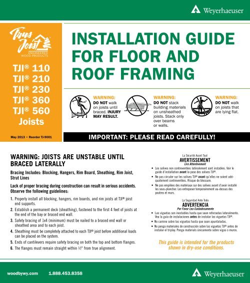
WARNING: JOISTS ARE UNSTABLE UNTIL<br />
BRACED LATERALLY<br />
Bracing Includes: Blocking, Hangers, Rim Board, Sheathing, Rim Joist,<br />
Strut Lines<br />
Lack of proper bracing during construction can result in serious accidents.<br />
Observe the following guidelines:<br />
1. Properly install all blocking, hangers, rim boards, <strong>and</strong> rim joists at <strong>TJI</strong> ® joist<br />
end supports.<br />
2. Establish a permanent deck (sheathing), fastened to the first 4 feet of joists at<br />
the end of the bay or braced end wall.<br />
3. Safety bracing of 1x4 (minimum) must be nailed to a braced end wall or<br />
sheathed area <strong>and</strong> to each joist.<br />
4. Sheathing must be completely attached to each <strong>TJI</strong> ® joist be<strong>for</strong>e additional loads<br />
can be placed on the system.<br />
5. Ends of cantilevers require safety bracing on both the top <strong>and</strong> bottom flanges.<br />
6. The flanges must remain straight within 1 ⁄2" from true alignment.<br />
La Sécurité Avant Tout<br />
AVERTISSEMENT<br />
Lire Attentivement<br />
• Les solives non contreventées latéralement sont instables. Voir le<br />
guide d’installation avant la pose des solives <strong>TJI</strong> ® .<br />
• Ne pas circuler sur les solives <strong>TJI</strong> ® avant qu’elles ne soient adéquatement<br />
contreventées. Risque de blessure.<br />
• Ne pas empilées des matériaux sur des solives avant d’avoir installé<br />
les sous-plancher. Les entreposer temporairement au-dessus des<br />
poutres et murs.<br />
La Seguridad Ante Todo<br />
ADVERTENCIA<br />
Por Favor Lea Cuidadosamente<br />
• Las viguetas son inestables hasta que sean re<strong>for</strong>zadas lateralmente.<br />
Vea la guía de instalaciones antes de instalar las viguetas <strong>TJI</strong> ® .<br />
• No camine sobre las viguetas hasta que sean apuntaladas.<br />
• No ponga materiales de construcción sobre las viguetas <strong>TJI</strong> ® antes de<br />
instalar el triplay. Ponga materials únicamente sobre vigas o muros.<br />
This guide is intended <strong>for</strong> the products<br />
shown in dry-use conditions.<br />
woodbywy.com 1.888.453.8358
CONTENTS<br />
Floor<br />
Allowable Holes:<br />
Trus Joist ® <strong>TJI</strong> ® Joists. ............. 1<br />
<strong>TJI</strong> ® Joist Nailing<br />
Requirements at Bearing. .......... 2<br />
<strong>Installation</strong> Recommendations. ...... 2<br />
<strong>TJI</strong> ® Joist Floor Framing. ........... 3<br />
Fastening of Floor Panels. .......... 3<br />
Rim Board Details <strong>and</strong> <strong>Installation</strong>. ... 4<br />
Floor Details. ................. 4–5<br />
Cantilever Details ................ 5<br />
Filler <strong>and</strong> Backer Blocks. .......... 5<br />
Web Stiffeners. .................. 6<br />
Framing Connectors. .............. 8<br />
Roof <strong>and</strong> Wall<br />
Allowable Holes:<br />
Trus Joist ® TimberStr<strong>and</strong> ® LSL<br />
Wall Studs. . . . . . . . . . . . . . . . . . . . . . 2<br />
Web Stiffeners. .................. 6<br />
Typical Roof <strong>and</strong> Wall Framing. ...... 6<br />
Ceiling Joists. ................... 6<br />
Roof Details. .................... 7<br />
Framing Connectors. .............. 8<br />
Shear Blocking <strong>and</strong> Ventilation Holes. . 8<br />
<strong>TJI</strong> ® Joist Nailing<br />
Requirements at Bearing. .......... 8<br />
1<br />
Beam <strong>and</strong> Column<br />
Allowable Holes:<br />
Trus Joist ® TimberStr<strong>and</strong> ® LSL,<br />
Parallam ® PSL, Microllam ® LVL<br />
Headers <strong>and</strong> Beams. .............. 2<br />
Beam <strong>and</strong> Column Details .......... 9<br />
Beam <strong>and</strong> Header Bearings ......... 9<br />
BUILD SAFELY<br />
We at <strong>Weyerhaeuser</strong> are committed to working safely <strong>and</strong> want<br />
to remind you to do the same. We encourage you to follow the<br />
recommendations of OSHA (www.osha.gov) in the U.S. or provincial<br />
regulations (www.canoshweb.org/en/) in Canada regarding:<br />
– Personal protective equipment (PPE) <strong>for</strong> h<strong>and</strong>s, feet, head,<br />
<strong>and</strong> eyes<br />
– Fall protection<br />
– Use of pneumatic nailers <strong>and</strong> other h<strong>and</strong> tools<br />
– Forklift safety<br />
Please adhere to the <strong>Weyerhaeuser</strong> product installation details,<br />
including the installation of safety bracing on unsheathed floors<br />
<strong>and</strong> roofs.<br />
PRODUCT IDENTIFICATION<br />
1 3 ⁄4"<br />
2 1 ⁄16" 2 5 ⁄16" 2 5 ⁄16" 3 1 ⁄2"<br />
1 1 ⁄4"–1 3 ⁄8" 1 1 ⁄4"–1 3 ⁄8" 1 1 ⁄4"–1 3 ⁄8" 1 3 ⁄8" 1 3 ⁄8"<br />
9½"<br />
9½"<br />
9½"<br />
9½"<br />
11<br />
3⁄8" 11 7 ⁄8"<br />
3⁄8" 7 ⁄8"<br />
3<br />
11<br />
⁄8" 7 ⁄8"<br />
11 3⁄8" 7 ⁄8"<br />
7<br />
14"<br />
⁄16"<br />
14"<br />
14"<br />
14"<br />
16"<br />
16"<br />
16"<br />
9½"<br />
11 7 ⁄8"<br />
14"<br />
16"<br />
<strong>TJI</strong> ® <strong>110</strong> joists <strong>TJI</strong> ® <strong>210</strong> joists <strong>TJI</strong> ® <strong>230</strong> joists <strong>TJI</strong> ® <strong>360</strong> joists <strong>TJI</strong> ® 560 joists<br />
ALLOWABLE HOLES—<strong>TJI</strong> ® JOISTS<br />
DO NOT cut holes<br />
in cantilever<br />
rein<strong>for</strong>cement.<br />
Min. distance from Table A<br />
6"<br />
OR<br />
Min. distance from Table B<br />
6"<br />
1½" hole<br />
may be cut<br />
anywhere in<br />
web outside of<br />
hatched zone<br />
DO NOT cut or<br />
notch flange.<br />
6"<br />
No field<br />
cut holes<br />
in hatched<br />
zone<br />
L 1 2 x D 1 D 1<br />
minimum<br />
(applies to all<br />
holes except<br />
knockouts)<br />
Closely grouped round<br />
holes are permitted if<br />
the group perimeter<br />
meets requirements <strong>for</strong><br />
round or square holes<br />
L 2<br />
2 x L 2<br />
minimum<br />
D 2<br />
6"<br />
No field<br />
cut holes<br />
in hatched<br />
zone<br />
6"<br />
Do not cut<br />
holes larger<br />
than 1 1 /2" in<br />
cantilever
Table A—End Support<br />
Minimum distance from edge of hole to inside face of nearest end support<br />
Joist<br />
Depth<br />
9 1 ⁄2"<br />
11 7 ⁄8"<br />
14"<br />
16"<br />
Round Hole Size Square or Rectangular Hole Size<br />
<strong>TJI</strong> ® 2" 3" 4" 6 1 ⁄2" 8 7 ⁄8" 11" 13" 2" 3" 4" 6 1 ⁄2" 8 7 ⁄8" 11" 13"<br />
<strong>110</strong> 1'-0" 1'-6" 2'-0" 5'-0" 1'-0" 1'-6" 2'-6" 4'-6"<br />
<strong>210</strong> 1'-0" 1'-6" 2'-6" 5'-6" 1'-0" 2'-0" 2'-6" 5'-0"<br />
<strong>230</strong> 1'-6" 2'-0" 2'-6" 5'-6" 1'-0" 2'-0" 3'-0" 5'-0"<br />
<strong>360</strong> 1'-6" 2'-0" 3'-0" 6'-0" 1'-6" 2'-6" 3'-6" 5'-6"<br />
560 1'-6" 2'-6" 3'-6" 7'-0" 2'-0" 3'-0" 4'-0" 6'-0"<br />
<strong>110</strong> 1'-0" 1'-0" 1'-6" 2'-6" 5'-6" 1'-0" 1'-6" 2'-0" 4'-6" 6'-0"<br />
<strong>210</strong> 1'-0" 1'-6" 2'-0" 3'-0" 6'-0" 1'-0" 1'-6" 2'-6" 5'-0" 6'-6"<br />
<strong>230</strong> 1'-0" 1'-6" 2'-0" 3'-0" 6'-6" 1'-0" 2'-0" 2'-6" 5'-6" 7'-0"<br />
<strong>360</strong> 1'-6" 2'-0" 3'-0" 4'-6" 7'-0" 1'-6" 2'-6" 3'-6" 6'-6" 7'-6"<br />
560 1'-6" 2'-6" 3'-0" 5'-6" 8'-0" 2'-6" 3'-6" 4'-6" 7'-0" 8'-0"<br />
<strong>110</strong> 1'-0" 1'-0" 1'-0" 1'-6" 3'-0" 5'-6" 1'-0" 1'-0" 1'-6" 3'-6" 6'-0" 8'-0"<br />
<strong>210</strong> 1'-0" 1'-0" 1'-0" 2'-0" 3'-6" 6'-0" 1'-0" 1'-0" 2'-0" 4'-0" 6'-6" 8'-6"<br />
<strong>230</strong> 1'-0" 1'-0" 1'-0" 2'-6" 4'-0" 7'-0" 1'-0" 1'-0" 2'-0" 4'-0" 7'-0" 9'-0"<br />
<strong>360</strong> 1'-0" 1'-0" 1'-6" 3'-6" 5'-6" 8'-0" 1'-0" 1'-6" 2'-6" 6'-0" 8'-0" 9'-6"<br />
560 1'-0" 1'-0" 2'-0" 4'-6" 6'-6" 9'-0" 1'-6" 3'-0" 4'-0" 7'-0" 9'-0" 10'-0"<br />
<strong>210</strong> 1'-0" 1'-0" 1'-0" 1'-0" 2'-6" 3'-6" 6'-0" 1'-0" 1'-0" 1'-0" 3'-0" 6'-6" 8'-0" 11'-0"<br />
<strong>230</strong> 1'-0" 1'-0" 1'-0" 1'-6" 3'-0" 4'-0" 7'-0" 1'-0" 1'-0" 1'-0" 3'-6" 7'-0" 9'-0" 11'-0"<br />
<strong>360</strong> 1'-0" 1'-0" 1'-0" 2'-6" 4'-6" 6'-6" 9'-0" 1'-0" 1'-0" 1'-6" 5'-0" 9'-0" 10'-0" 11'-6"<br />
560 1'-0" 1'-0" 1'-0" 2'-6" 5'-0" 7'-6" 10'-0" 1'-0" 2'-0" 3'-0" 6'-6" 10'-0" 11'-0" 12'-0"<br />
Table B—Intermediate or Cantilever Support<br />
Minimum distance from edge of hole to inside face of nearest intermediate or cantilever support<br />
Joist<br />
Depth<br />
9 1 ⁄2"<br />
11 7 ⁄8"<br />
14"<br />
16"<br />
Round Hole Size Square or Rectangular Hole Size<br />
<strong>TJI</strong> ® 2" 3" 4" 6 1 ⁄2" 8 7 ⁄8" 11" 13" 2" 3" 4" 6 1 ⁄2" 8 7 ⁄8" 11" 13"<br />
<strong>110</strong> 2'-0" 2'-6" 3'-6" 7'-6" 1'-6" 2'-6" 3'-6" 6'-6"<br />
<strong>210</strong> 2'-0" 2'-6" 3'-6" 8'-0" 2'-0" 3'-0" 4'-0" 7'-6"<br />
<strong>230</strong> 2'-6" 3'-0" 4'-0" 8'-6" 2'-0" 3'-6" 4'-6" 7'-6"<br />
<strong>360</strong> 3'-0" 4'-0" 5'-6" 9'-0" 3'-0" 4'-6" 5'-6" 8'-0"<br />
560 3'-6" 5'-0" 6'-0" 10'-0" 4'-0" 5'-6" 6'-6" 9'-0"<br />
<strong>110</strong> 1'-0" 1'-0" 1'-6" 4'-0" 8'-6" 1'-0" 1'-6" 2'-6" 7'-0" 9'-6"<br />
<strong>210</strong> 1'-0" 1'-0" 2'-0" 4'-6" 9'-0" 1'-0" 2'-0" 3'-0" 8'-0" 10'-0"<br />
<strong>230</strong> 1'-0" 2'-0" 2'-6" 5'-0" 10'-0" 1'-0" 2'-6" 3'-6" 8'-6" 10'-6"<br />
<strong>360</strong> 2'-0" 3'-0" 4'-0" 7'-0" 11'-0" 2'-0" 3'-6" 5'-0" 9'-6" 11'-0"<br />
560 1'-6" 3'-0" 4'-6" 8'-0" 12'-0" 3'-0" 4'-6" 6'-0" 10'-6" 12'-0"<br />
<strong>110</strong> 1'-0" 1'-0" 1'-0" 2'-0" 4'-6" 8'-6" 1'-0" 1'-0" 1'-0" 5'-0" 9'-0" 12'-0"<br />
<strong>210</strong> 1'-0" 1'-0" 1'-0" 2'-6" 5'-6" 9'-6" 1'-0" 1'-0" 2'-0" 6'-0" 10'-0" 13'-0"<br />
<strong>230</strong> 1'-0" 1'-0" 1'-0" 3'-6" 6'-0" 10'-6" 1'-0" 1'-0" 2'-6" 6'-6" 11'-0" 13'-6"<br />
<strong>360</strong> 1'-0" 1'-0" 2'-0" 5'-6" 8'-6" 12'-6" 1'-0" 2'-0" 4'-0" 9'-0" 12'-0" 14'-0"<br />
560 1'-0" 1'-0" 1'-6" 5'-6" 9'-6" 13'-6" 1'-0" 3'-0" 5'-0" 10'-0" 13'-6" 15'-0"<br />
<strong>210</strong> 1'-0" 1'-0" 1'-0" 1'-0" 3'-6" 6'-0" 10'-0" 1'-0" 1'-0" 1'-0" 4'-6" 10'-0" 12'-6" 16'-0"<br />
<strong>230</strong> 1'-0" 1'-0" 1'-0" 1'-6" 4'-0" 6'-6" 11'-0" 1'-0" 1'-0" 1'-0" 5'-0" 10'-6" 13'-6" 16'-6"<br />
<strong>360</strong> 1'-0" 1'-0" 1'-0" 3'-0" 6'-6" 10'-0" 13'-6" 1'-0" 1'-0" 2'-0" 7'-6" 13'-0" 14'-6" 17'-0"<br />
560 1'-0" 1'-0" 1'-0" 2'-6" 7'-0" 11'-0" 15'-0" 1'-0" 1'-0" 3'-6" 9'-0" 14'-6" 16'-0" 18'-0"<br />
■<br />
Leave 1 ⁄8" of web (minimum) at top <strong>and</strong> bottom of hole. DO NOT cut joist flanges.<br />
■<br />
Tables are based on uni<strong>for</strong>m load tables in current design literature.<br />
■<br />
For simple span (5' minimum), uni<strong>for</strong>mly loaded joists used in residential applications, one maximum size round hole may be<br />
located at the center of the joist span provided that no other holes occur in the joist.
ALLOWABLE HOLES—BEAMS <strong>and</strong> STUDS<br />
1.55E TimberStr<strong>and</strong> ® LSL Headers <strong>and</strong> Beams<br />
1⁄3 depth<br />
2 x diameter of the largest hole (minimum)<br />
Allowed hole zone<br />
1.55E TimberStr<strong>and</strong> ® LSL<br />
2<br />
GENERAL NOTES<br />
Other Trus Joist ® Headers <strong>and</strong> Beams<br />
1.3E<br />
TimberStr<strong>and</strong> ® LSL<br />
hole zone<br />
d<br />
GENERAL NOTES<br />
8" 8"<br />
■<br />
Allowed hole zone suitable <strong>for</strong> headers <strong>and</strong><br />
beams with uni<strong>for</strong>m <strong>and</strong>/or concentrated<br />
loads anywhere along the member.<br />
d<br />
Microllam ® LVL <strong>and</strong><br />
Parallam ® PSL hole<br />
zone<br />
■<br />
Allowed hole zone suitable <strong>for</strong> headers<br />
<strong>and</strong> beams with uni<strong>for</strong>m loads only.<br />
■<br />
No holes in cantilevers.<br />
Microllam ® LVL <strong>and</strong><br />
Parallam ® PSL<br />
allowed hole zone<br />
middle 1 ⁄3 span<br />
TimberStr<strong>and</strong> ® LSL Wall Studs<br />
2 x diameter of<br />
the largest hole<br />
(minimum)<br />
1.3E TimberStr<strong>and</strong> ® LSL allowed hole zone<br />
■<br />
Round holes only.<br />
■<br />
No holes in headers or beams in plank<br />
orientation.<br />
■<br />
Round holes only.<br />
d<br />
1 ⁄3 depth<br />
■<br />
No holes in headers or beams in plank<br />
orientation.<br />
Header or<br />
Beam<br />
Depth<br />
91⁄4"–91⁄2" 3"<br />
111⁄4"–11 7 ⁄8" 3 5 ⁄8"<br />
14"–16" 4 5 ⁄8"<br />
■ <br />
See illustration <strong>for</strong><br />
allowed hole zone.<br />
Header or<br />
Beam<br />
Depth<br />
Maximum<br />
Round Hole<br />
Size<br />
DO NOT cut, notch, or<br />
drill holes in headers<br />
or beams except<br />
as indicated in the<br />
illustrations <strong>and</strong> tables.<br />
Other Trus Joist ® Beams<br />
■<br />
Maximum<br />
Round Hole<br />
Size<br />
4 3 ⁄8" 1"<br />
51⁄2" 1 3 ⁄4"<br />
71⁄4"–20" 2"<br />
<br />
See illustration <strong>for</strong><br />
allowed hole zone.<br />
One notch may be cut anywhere except the middle 1 ⁄3 of the length of the stud or column.<br />
Holes may be drilled anywhere along the length of the stud or column but must be at least 5 ⁄8" from the edge.<br />
5⁄8" minimum edge distance<br />
Maximum diameter: 1 3 ⁄8" <strong>for</strong> 3 1 ⁄2"<br />
thick walls (1 1 ⁄8" in Canada);<br />
2 3 ⁄16" <strong>for</strong> 5 1 ⁄2"–11 7 ⁄8" thick walls<br />
(1 13 ⁄16" in Canada)<br />
Maximum notch:<br />
7⁄8" <strong>for</strong> 3 1 ⁄2" thick walls<br />
1 3 ⁄8" <strong>for</strong> 5 1 ⁄2"–11 7 ⁄8"<br />
thick walls<br />
DO NOT cut a notch<br />
<strong>and</strong> a hole in the<br />
same cross section.
<strong>TJI</strong> ® JOIST NAILING REQUIREMENTS AT BEARING<br />
<strong>TJI</strong> ® Joist to Bearing Plate<br />
1 1 ⁄8" TJ ® Rim Board or 1 1 ⁄4" TimberStr<strong>and</strong> ® LSL<br />
Squash Blocks to <strong>TJI</strong> ® Joist<br />
(Load bearing wall above)<br />
One 8d (0.113" x 2 1 ⁄2") nail each<br />
side. Drive nails at an angle<br />
at least 1 1 ⁄2" from end.<br />
One 10d (0.128" x 3")<br />
nail into each flange<br />
1 3 ⁄4" minimum end bearing <strong>for</strong><br />
single-family applications<br />
■<br />
Increased bearing capacities may be achieved with increased bearing<br />
lengths. See plans <strong>for</strong> required bearing lengths.<br />
Shear transfer nailing: Use connections equivalent to floor panel nailing<br />
schedule. See page 4.<br />
1 3 ⁄4" minimum<br />
bearing<br />
3 1 ⁄2" minimum intermediate<br />
bearing; 5 1 ⁄4" may be required<br />
<strong>for</strong> maximum capacity<br />
Rim to <strong>TJI</strong> ® Joist<br />
1 1 ⁄8" TJ ® Rim Board, 1 1 ⁄4" TimberStr<strong>and</strong> ® LSL,<br />
or <strong>TJI</strong> ® <strong>110</strong> rim joist:<br />
One 10d (0.131" x 3") nail into each flange<br />
<strong>TJI</strong> ® <strong>210</strong>, <strong>230</strong>, <strong>and</strong> <strong>360</strong> rim joist:<br />
One 16d (0.135" x 3 1 ⁄2") nail into each flange<br />
Locate rim board joint between joists<br />
<strong>TJI</strong> ® 560 rim joist:<br />
Toenail with 10d (0.128" x 3")<br />
nails, one each side of<br />
<strong>TJI</strong> ® joist flange<br />
Also see detail B2, page 5<br />
Top View<br />
<strong>TJI</strong> ® 560 floor joist<br />
<strong>TJI</strong> ® 560 rim joist<br />
INSTALLATION RECOMMENDATIONS<br />
RECOMMENDED COMPONENTS<br />
■<br />
<strong>Weyerhaeuser</strong> Edge Gold floor panels<br />
■<br />
<strong>TJI</strong> ® joists<br />
■<br />
1 1 ⁄8" TJ ® Rim Board or 1 1 ⁄4" TimberStr<strong>and</strong> ® LSL<br />
RECOMMENDED ADHESIVES<br />
■<br />
<strong>Weyerhaeuser</strong> recommends using solvent-based subfloor adhesives<br />
that meet ASTM D3498 (AFG-01) per<strong>for</strong>mance st<strong>and</strong>ards.<br />
When latex subfloor adhesive is required, careful selection is<br />
necessary due to a wide range of per<strong>for</strong>mance between br<strong>and</strong>s.<br />
Apply a 1 ⁄4" or larger<br />
bead of adhesive<br />
DOWN PORE<br />
DRAINAGE THIS END<br />
At abutting panel edges,<br />
apply two 1 ⁄4" beads of adhesive<br />
DOWN PORE<br />
DRAINAGE THIS END<br />
DOWN PORE<br />
DRAINAGE THIS END<br />
DOWN PORE<br />
DRAINAGE THIS END<br />
DOWN P<br />
DRAINAGE T<br />
Nail panel to joist at 12" on-center in field <strong>and</strong> 6" on-center along<br />
panel edges. Apply fasteners 3 ⁄8" from panel edges.<br />
■<br />
For 3 ⁄4" panels, use 8d (0.131" x 2 1 ⁄2") or 6d (0.120" x 2")<br />
de<strong>for</strong>med-shank nails or other code-approved fasteners.<br />
■<br />
For 7 ⁄8" panels, use 8d (0.131" x 2 1 ⁄2") or 8d (0.120" x 2 1 ⁄2")<br />
de<strong>for</strong>med-shank nails or other code-approved fasteners.<br />
■<br />
Fully nail floor panel within 10 minutes of applying adhesive (or<br />
sooner if required by adhesive manufacturer).<br />
■<br />
Screws may be substituted <strong>for</strong> the nails noted above if the screws<br />
have equivalent lateral load capacity.
<strong>TJI</strong> ® JOIST FLOOR FRAMING<br />
3<br />
<strong>TJI</strong> ® joist floor framing does not require<br />
bridging or mid-span blocking<br />
<strong>TJI</strong> ®<br />
rim joist<br />
P<br />
A2<br />
L5<br />
DO NOT use sawn lumber <strong>for</strong><br />
rim board or blocking as it<br />
may shrink after installation.<br />
Use only engineered lumber.<br />
E2<br />
B4<br />
A1<br />
B3<br />
B2<br />
B1<br />
H2<br />
See Filler <strong>and</strong><br />
Backer Blocks<br />
on page 5<br />
CS<br />
Use B1 or B2 at<br />
intermediate bearings<br />
with load bearing or<br />
shear wall from above<br />
WARNING<br />
Joists are unstable until laterally braced.<br />
See Warning on cover.<br />
E1<br />
L3<br />
Joists must be laterally supported at<br />
cantilever <strong>and</strong> end bearings by blocking<br />
panels, hangers, or direct attachment to<br />
a rim board or rim joist.<br />
A3_<br />
H1<br />
Rim board joint between joists<br />
1 1 ⁄8" TJ ® Rim Board or<br />
1 1 ⁄4" TimberStr<strong>and</strong> ® LSL<br />
L1<br />
End of<br />
joists at<br />
centerline<br />
of support<br />
L4<br />
H1<br />
L2<br />
LA<br />
Safety bracing (1x4 minimum)<br />
at 8' on-center (6' on-center <strong>for</strong><br />
<strong>TJI</strong> ® <strong>110</strong> joists) <strong>and</strong> extended to a<br />
braced end wall. Fasten at each joist<br />
with two 8d (0.113" x 2 1 ⁄2") nails<br />
minimum (see Warning on cover).<br />
Protect untreated<br />
wood from direct<br />
contact with<br />
concrete<br />
INSTALLATION TIPS<br />
1 1 ⁄2" knockouts<br />
at approximately<br />
12" on-center<br />
Bearing plate to be<br />
flush with inside<br />
face of wall or beam<br />
H3<br />
See<br />
Allowable Holes<br />
on page 1<br />
■<br />
Subfloor adhesive will improve floor per<strong>for</strong>mance, but may<br />
not be required.<br />
■<br />
Squash blocks <strong>and</strong> blocking panels carry stacked vertical<br />
loads (details B1 <strong>and</strong> B2). Packing out the web of a <strong>TJI</strong> ® joist<br />
(with web stiffeners) is not a substitute <strong>for</strong> squash blocks or<br />
blocking panels.<br />
Structural<br />
sheathing<br />
See Exterior Deck<br />
Attachment on page 4<br />
Shifted joist<br />
Plumbing drop<br />
Additional joist<br />
■<br />
When joists are doubled at non-load bearing parallel<br />
partitions, space joists apart the width of the wall <strong>for</strong><br />
plumbing or HVAC.<br />
■<br />
Additional joist at plumbing drop (see detail above).
End bearings (see page 4)<br />
A1<br />
A2<br />
A3_<br />
with blocking panels<br />
with <strong>TJI</strong> ® rim joist<br />
with rim board<br />
Intermediate bearings* (see page 5)<br />
B1 with blocking panels to support<br />
load bearing wall above<br />
B2 with squash blocks to support<br />
load bearing wall above<br />
B3 without blocking panels or<br />
squash blocks (no wall above)<br />
Cantilever details (see page 5)<br />
E1 no rein<strong>for</strong>cement<br />
E2 3 ⁄4" rein<strong>for</strong>cement on one side<br />
DETAIL SCHEDULE<br />
E3 3 ⁄4" rein<strong>for</strong>cement both sides<br />
E4 joist rein<strong>for</strong>cement<br />
F1 deck cantilever<br />
PB1 permanent bracing<br />
Cantilevers less than 5" (see page 5)<br />
E5 3 ⁄4" rein<strong>for</strong>cement on one side,<br />
with vertical blocking<br />
E6 3 ⁄4" rein<strong>for</strong>cement both sides,<br />
with vertical blocking<br />
E7 3 ⁄4" rein<strong>for</strong>cement on one side,<br />
with horizontal blocking<br />
E8 3 ⁄4" rein<strong>for</strong>cement on both sides,<br />
with horizontal blocking<br />
Hanger Details<br />
(more connector in<strong>for</strong>mation on page 8)<br />
H1 <strong>TJI</strong> ® joist to beam (see page 8)<br />
H2 <strong>TJI</strong> ® joist to joist (see page 5)<br />
H3 <strong>TJI</strong> ® joist on masonry wall or steel<br />
beam (see page 8)<br />
Other details<br />
B4 butting joists with blocking panels<br />
(see above)<br />
CS column support (see page 4)<br />
LA exterior deck attachment (see page 4)<br />
W web stiffeners (see page 6)<br />
L beam details (see page 9)<br />
P column details (see page 9)<br />
*Load bearing wall must stack over wall below. Blocking panels may be required at shear walls above or below.<br />
JAVELIN ® SOFTWARE FRAMING PLANS<br />
A_ B_ E_<br />
W W W Web stiffeners required on each side of joist at bearing. Refer to your Javelin ® framing plan.<br />
Bearing requirements as shown on the Javelin ® framing plan are job-specific <strong>and</strong> supersede minimum bearing requirements listed.<br />
FASTENING OF FLOOR PANELS<br />
<strong>Guide</strong>lines <strong>for</strong> Closest On-Center Spacing per Row<br />
Nail Size<br />
<strong>110</strong>, <strong>210</strong>,<br />
<strong>and</strong> <strong>230</strong><br />
<strong>TJI</strong> ®(1)(2) Rim board 1 1 ⁄2"<br />
<strong>360</strong> <strong>and</strong><br />
1<br />
560<br />
1 ⁄8" TJ ® 1 1 ⁄4"<br />
TimberStr<strong>and</strong> ® LSL<br />
8d (0.113" x 2 1 ⁄2"), 8d (0.131" x 2 1 ⁄2") 4" 3" 6" 4" 3" 3" 3"<br />
10d (0.148" x 3"), 12d (0.148" x 3 1 ⁄4") 4" (3) 4" (3) 6" 4" 4" 4" 4"<br />
16d (0.162" x 3 1 ⁄2") 6" 6" 16" 6" (4) 6" (4) 8" 6"<br />
(1) Stagger nails when using 4" on‐center spacing <strong>and</strong> maintain 3 ⁄8" joist <strong>and</strong> panel edge distance. One row of fasteners is permitted (two at abutting panel<br />
edges) <strong>for</strong> diaphragms. Fastener spacing <strong>for</strong> <strong>TJI</strong> ® joists in diaphragm applications cannot be less than shown in table. When fastener spacing <strong>for</strong><br />
blocking is less than spacing shown above, rectangular blocking must be used in lieu of <strong>TJI</strong> ® joists.<br />
(2) For non-diaphragm applications, multiple rows of fasteners are permitted if the rows are offset at least ½" <strong>and</strong> staggered.<br />
(3) Can be reduced to 3" on-center <strong>for</strong> light gauge steel straps with 10d (0.148" x 1½") nails.<br />
(4) Can be reduced to 4" on-center if nail penetration into the narrow edge is no more than 1 3 ⁄8" (to avoid splitting).<br />
■<br />
Recommended nailing is 12" on-center in field <strong>and</strong> 6" on-center<br />
along panel edge. Fastening requirements on engineered drawings<br />
supersede recommendations listed above.<br />
■<br />
<strong>Weyerhaeuser</strong> recommends using a solvent-based subfloor adhesive<br />
on all contact points between panels <strong>and</strong> floor framing. See<br />
RECOMMENDED ADHESIVES on page 2.<br />
TimberStr<strong>and</strong> ® LSL<br />
or wider<br />
Microllam ®<br />
LVL<br />
Parallam ®<br />
PSL<br />
■<br />
Nailing rows must be offset at least 1 ⁄2" <strong>and</strong> staggered.<br />
■<br />
14 ga. staples may be substituted <strong>for</strong> 8d (0.113" x 2 1 ⁄2")<br />
nails if minimum penetration of 1" into the <strong>TJI</strong> ® joist or<br />
rim board is achieved.<br />
■<br />
Maximum spacing of nails is 18" on-center <strong>for</strong><br />
<strong>TJI</strong> ® joists.
RIM BOARD DETAILS AND INSTALLATION<br />
Plate nail<br />
Floor panel nail<br />
Rim board to <strong>TJI</strong> ® joist<br />
1 1 ⁄8" TJ ® Rim Board or<br />
1 1 ⁄4" TimberStr<strong>and</strong> ® LSL<br />
(see nailing schedule below)<br />
Toe nail<br />
Rim board to <strong>TJI</strong> ® joist<br />
Sheathing may be attached<br />
as shown in A3.4<br />
2x4 or 2x6 stud wall<br />
at 16" on-center<br />
When<br />
panel<br />
thickness<br />
exceeds 7 ⁄8",<br />
trim sheathing<br />
tongue at<br />
rim board<br />
<strong>TJI</strong> ® joist spanning<br />
in either direction<br />
<strong>TJI</strong> ® joist to plate<br />
Web stiffener required on<br />
both sides at A3._W ONLY<br />
Plate nail<br />
Floor panel nail<br />
Rim board to <strong>TJI</strong> ® joist<br />
1 1 ⁄4" TimberStr<strong>and</strong> ® LSL<br />
rim board<br />
Attach sheathing per<br />
nailing schedule (below)<br />
Toe nail<br />
Rim board to <strong>TJI</strong> ® joist<br />
12" minimum<br />
Install proper blocking to<br />
support all panel edges<br />
A3.1 A3.2 A3.3 A3.1<br />
W A3.2<br />
W A3.3<br />
A3.4<br />
W<br />
A3.4<br />
W<br />
2x4 or 2x6 stud wall<br />
at 16" on-center<br />
Web stiffener required on<br />
both sides at A3.4W ONLY<br />
4<br />
When panel<br />
thickness<br />
exceeds 7 ⁄8",<br />
trim sheathing<br />
tongue at<br />
rim board<br />
<strong>TJI</strong> ® joist spanning<br />
in either direction<br />
<strong>TJI</strong> ® joist to plate<br />
Wall Framing<br />
Specifications<br />
Rim Board <strong>Installation</strong> Detail<br />
A3.1 (1)(2) A3.2 (1)(2) A3.3 (1) A3.4 (1)<br />
Rim Board Thickness 1 1 ⁄8" 11⁄4" 11⁄4" 11⁄4"<br />
Plate Nail—16d (0.135" x 3 1 ⁄2") 16" o.c. 12" o.c. 8" o.c. 12" o.c.<br />
Floor Panel Nail—8d (0.131" x 2 1 ⁄2")<br />
6" o.c.<br />
Rim Board to <strong>TJI</strong> ® Joist—10d (0.131" x 3")<br />
One into each flange<br />
Toe Nail—10d (0.131" x 3") 6" o.c. 6" o.c. 4" o.c. 6" o.c.<br />
<strong>TJI</strong> ® Joist to Plate—8d (0.113" x 2 1 ⁄2") Two nails driven at an angle into bottom flange, one each side of web at least 1½" from end<br />
Sheathing<br />
7⁄16" structural 1<br />
3 ⁄8" structural 1<br />
sheathing (3) sheathing in all areas (4)<br />
Boundary Nailing 8d (0.131" x 2½") at 6" o.c. 8d (0.131" x 2½") at 4" o.c.<br />
Per Code<br />
Per Code<br />
Intermediate Nailing<br />
8d (0.131" x 2½") at 12" o.c.<br />
Max. Window Opening Height 5'-4" (5)<br />
% of Wall with Full Height Sheathing 70%<br />
Exterior Face<br />
Interior<br />
Face<br />
Holdowns<br />
Sheathing<br />
½" gypsum<br />
Boundary Nailing<br />
Per Code<br />
Per Code<br />
5d (0.086" x 1 5 ⁄8") at 7" o.c.<br />
Intermediate Nailing<br />
5d (0.086" x 1 5 ⁄8") at 10" o.c.<br />
90 mph Wind Zone None<br />
120 mph Wind Zone<br />
16" o.c. within 10' 16" o.c. within 6' 16" o.c. within 4'<br />
of corners (6) of corners (6) of corners (6)<br />
none<br />
(1) All sheathing shall be properly blocked <strong>and</strong> nailed.<br />
(2) Verify the lateral capacity of the wall. Not all types of code-allowed wall construction provide the same lateral resistance. Check with your<br />
local building official or design professional of record.<br />
(3) Detail A3.3 shall be a segmented wall, location of full-height structural sheathing per code.<br />
(4) Sheathing shall be continuous over all plate-to-plate <strong>and</strong> plate-to-rim-board interfaces <strong>and</strong> may butt together at mid-depth of rim board<br />
as shown in A3.4. At foundation, fasten the bottom edge of the sheathing to the sill plate.<br />
(5) In addition, one 6'-8" st<strong>and</strong>ard door opening is allowed.<br />
(6) If required, holdowns shall be Simpson Strong-Tie ® CS20 (or equivalent) straps attached with four 8d (0.131" x 2 1 ⁄2") nails at each end.<br />
As an alternative to holdown straps, wall sheathing may be attached as shown in A3.4. See footnote 4.
FLOOR DETAILS<br />
Plate nail<br />
Blocking panel:<br />
1 1 ⁄8" TJ ® Rim Board,<br />
1 1 ⁄4" TimberStr<strong>and</strong> LSL,<br />
or <strong>TJI</strong> ® joist<br />
Plate nail<br />
Web stiffener required on<br />
both sides at A2W ONLY<br />
Rim-tojoist<br />
nail<br />
Toe nail<br />
Toe nail<br />
Web stiffener required on<br />
both sides at A1W ONLY<br />
<strong>TJI</strong> ® rim joist<br />
A1<br />
A1<br />
W<br />
Attach blocking per A3.1 in rim board<br />
installation table above<br />
A2<br />
A2<br />
W<br />
Must have 1¾" minimum joist bearing at ends. Attach<br />
rim joist per A3.1 in rim board installation table above.<br />
Exterior Deck Attachment<br />
Load from above<br />
Structural exterior<br />
sheathing<br />
Flashing<br />
1 1 ⁄8" TJ ® Rim Board or<br />
1 1 ⁄4" TimberStr<strong>and</strong> ® LSL<br />
Treated 2x_<br />
ledger<br />
2x4 minimum<br />
squash blocks<br />
1⁄16"<br />
Maintain 2" distance<br />
(minimum) from edge of<br />
ledger to fastener<br />
CS<br />
Use 2x4 minimum squash blocks to transfer load<br />
around <strong>TJI</strong> ® joist<br />
LA<br />
Corrosion-resistant fasteners required <strong>for</strong><br />
wet-service applications
FLOOR DETAILS 5<br />
Load bearing or braced/shear wall<br />
above (must stack over wall below)<br />
Blocking panel: 1 1 ⁄8" TJ ® Rim Board,<br />
1 1 ⁄4" TimberStr<strong>and</strong> LSL, or <strong>TJI</strong> ® joist<br />
No load bearing wall above<br />
2x4 minimum<br />
squash blocks<br />
B1<br />
B1W<br />
1 ⁄16"<br />
Web stiffener required on both<br />
sides at B1W or B2W ONLY.<br />
Web stiffener required on<br />
both sides at B3W ONLY.<br />
B2<br />
B2W<br />
Blocking panels may be required with braced/<br />
shear walls above or below—see detail B1<br />
B3<br />
B3W<br />
Blocking panels may be required with braced/<br />
shear walls above or below—see detail B1<br />
CANTILEVER DETAILS<br />
At PB1, cantilever back span<br />
must be permanently braced<br />
with either direct-applied ceiling<br />
along entire length or permanent<br />
bracing at 1 ⁄3 points. See detail<br />
below <strong>for</strong> connections.<br />
1 ⁄8" TJ ® Rim Board or<br />
1 1 ⁄4" TimberStr<strong>and</strong> ® LSL,<br />
typical. Nail with<br />
10d (0.131" x 3") nails,<br />
one each at top <strong>and</strong><br />
bottom flange.<br />
1 ⁄3<br />
8' max., typical<br />
1⁄3<br />
8" diameter maximum hole <strong>for</strong> 11 7 ⁄8"–16"<br />
deep blocking panels; 6" diameter maximum<br />
<strong>for</strong> blocking panels 9 1 ⁄2" deep or shorter than<br />
12" long. Do not cut flanges.<br />
Web stiffener<br />
required on both<br />
sides at E1W ONLY<br />
E1<br />
E1W<br />
E3<br />
E2<br />
1 1 ⁄8" TJ ® Rim Board or<br />
1 1 ⁄4" TimberStr<strong>and</strong> ® LSL<br />
closure, typical<br />
4'-0" length of 3 ⁄4"<br />
rein<strong>for</strong>cement (2'-0" maximum<br />
cantilever) on one side at E2,<br />
both sides at E3. Attach to joist<br />
flange with 8d (0.131" x 2 1 ⁄2")<br />
nails at 6" on-center. When<br />
rein<strong>for</strong>cing both sides,<br />
stagger nails.<br />
E4<br />
1 ⁄3<br />
E5<br />
12" length of 3 ⁄4"<br />
rein<strong>for</strong>cement on one side at<br />
E5/E7, both sides at E6/E8.<br />
Attach to joist flanges with<br />
one 8d (0.131" x 2 1 ⁄2") nail<br />
at each corner.<br />
E6<br />
Blocking panel between each joist.<br />
Full depth vertical blocking at E5 <strong>and</strong><br />
E6, horizontal blocking at E7 <strong>and</strong> E8.<br />
PB1<br />
E8<br />
E7<br />
Wood<br />
backer<br />
Less than<br />
5"<br />
Nail rim to blocking panel <strong>and</strong><br />
blocking panel to plate with<br />
connections equivalent to floor<br />
panel schedule (E7 <strong>and</strong> E8)<br />
F1<br />
4'-0" maximum<br />
(uni<strong>for</strong>m loads only)<br />
Nail through 2x_ cantilever, wood<br />
backer, <strong>and</strong> <strong>TJI</strong> ® joist web with 2 rows<br />
10d (0.148" x 3") nails at 6" on-center,<br />
clinched. Use 16d (0.135" x 3 1 ⁄2") nails<br />
with <strong>TJI</strong> ® 560 joists. F1 applies to<br />
uni<strong>for</strong>mly loaded joists only.<br />
1 1 ⁄2 times cantilever length Cantilever length<br />
6'-0" length of <strong>TJI</strong> ® joist rein<strong>for</strong>cement (2'-0"<br />
maximum cantilever) <strong>and</strong> filler block at E4. Attach<br />
to joist web with 3 rows 10d (0.148" x 3") nails at<br />
6" on-center, clinched. Use 4'-0" length with 9 1 ⁄2"<br />
<strong>and</strong> 11 7 ⁄8" <strong>TJI</strong> ® joists, <strong>and</strong> attach to joist web with<br />
2 rows 10d (0.148" x 3") nails at 6" on-center,<br />
clinched. Not <strong>for</strong> use with <strong>TJI</strong> ® 560 joists.<br />
Two 2 1 ⁄2" screws <strong>for</strong> 2x_<br />
strapping connections<br />
When specified on the layout,<br />
one of the bracing options<br />
shown at right is required<br />
PB1<br />
Apply subfloor adhesive to all<br />
contact surfaces<br />
Two 8d (0.113" x 2 1 ⁄2") nails<br />
or 2 1 ⁄2" screws, typical<br />
Directly applied ceiling<br />
FILLER AND BACKER BLOCKS<br />
HANGER BACKER BLOCK<br />
Install tight to top flange (tight to bottom flange with face mount hangers).<br />
■<br />
Single-Family Applications: Attach with ten 10d (0.128" x 3") nails, clinched<br />
when possible.<br />
■<br />
Multi-Family Applications: Attach with fifteen 10d (0.128" x 3") nails, clinched<br />
when possible.<br />
H2<br />
Backer block both<br />
sides of web with<br />
single <strong>TJI</strong> ® joist<br />
DOUBLE <strong>TJI</strong> ® JOIST FILLER BLOCK<br />
■<br />
Single-Family Applications: Attach with<br />
ten 10d (0.128" x 3") nails, clinched.<br />
Use ten 16d (0.135" x 3 1 ⁄2") nails from<br />
each side with <strong>TJI</strong> ® 560 joists.<br />
■<br />
Multi-Family Applications: Attach with<br />
fifteen 10d (0.128" x 3") nails, clinched.<br />
Use fifteen 16d (0.135" x 3 1 ⁄2") nails<br />
from each side with <strong>TJI</strong> ® 560 joists.<br />
Filler <strong>and</strong> Backer Block Sizes<br />
<strong>TJI</strong> ® <strong>110</strong> <strong>210</strong> <strong>230</strong> or <strong>360</strong> 560<br />
Depth<br />
9½" or<br />
11 7 ⁄8"<br />
14"<br />
9½" or<br />
11 7 ⁄8"<br />
14" or 16"<br />
9½" or<br />
11 7 ⁄8"<br />
14" or 16"<br />
9½" or 14" or<br />
11 7 ⁄8" 16"<br />
Filler<br />
Block (1)<br />
(Detail H2)<br />
Cantilever<br />
Filler<br />
(Detail E4)<br />
Backer<br />
Block (1)<br />
(Detail F1<br />
or H2)<br />
2x6<br />
2x6<br />
4'-0"<br />
long<br />
2x8<br />
2x10<br />
6'-0"<br />
long<br />
2x6 + 3 ⁄8"<br />
sheathing<br />
2x6 + 3 ⁄8"<br />
sheathing<br />
4'-0" long<br />
2x8 + 3 ⁄8"<br />
sheathing<br />
2x10 + 3 ⁄8"<br />
sheathing<br />
6'-0" long<br />
2x6 + ½"<br />
sheathing<br />
2x6 + ½"<br />
sheathing<br />
4'-0" long<br />
2x8 + ½"<br />
sheathing<br />
2x10 + ½"<br />
sheathing<br />
6'-0" long<br />
Two<br />
2x6<br />
Two<br />
2x8<br />
Not<br />
applicable<br />
5 ⁄8" or ¾" ¾" or 7 ⁄8" 7 ⁄8" or 1" net 2x6 2x8<br />
(1) If necessary, increase filler <strong>and</strong> backer block height <strong>for</strong> face mount hangers <strong>and</strong> maintain 1 ⁄8" gap at<br />
top of joist. See detail W. Filler <strong>and</strong> backer block dimensions should accommodate required nailing<br />
without splitting. The suggested minimum length is 24" <strong>for</strong> filler <strong>and</strong> 12" <strong>for</strong> backer blocks.
WEB STIFFENERS—FLOOR AND ROOF APPLICATIONS<br />
6<br />
1"<br />
(1 1 ⁄2" <strong>for</strong><br />
<strong>TJI</strong> ® 560<br />
joists)<br />
W<br />
WEB STIFFENER SIZES<br />
Gap:<br />
1⁄8" minimum<br />
2 3 ⁄4" maximum<br />
Three 8d (0.113" x 2 1 ⁄2")<br />
nails, clinched. Use three<br />
16d (0.135" x 3 1 ⁄2") nails<br />
<strong>for</strong> <strong>TJI</strong> ® 560 joists.<br />
Web stiffener both sides.<br />
See sizes below.<br />
Tight fit<br />
■<br />
<strong>TJI</strong> ® <strong>110</strong> joists: 5 ⁄8" x 2 5 ⁄16" minimum (1)<br />
■<br />
<strong>TJI</strong> ® <strong>210</strong> joists: 3 ⁄4" x 2 5 ⁄16" minimum (1)<br />
■<br />
<strong>TJI</strong> ® <strong>230</strong> <strong>and</strong> <strong>360</strong> joists: 7 ⁄8" x 2 5 ⁄16" minimum (1)<br />
■<br />
<strong>TJI</strong> ® 560 joists: 2x4, construction grade or better<br />
(1) PS1 or PS2 sheathing, face grain vertical<br />
WEB STIFFENER REQUIREMENTS<br />
Required at all<br />
birdsmouth cuts.<br />
Required at all<br />
sloped hangers.<br />
Required if the sides of the<br />
hanger do not extend to<br />
l aterally support at least 3 ⁄8"<br />
of the <strong>TJI</strong> ® joist top flange.<br />
Only required at intermediate<br />
bearing locations when noted<br />
on framing plan.<br />
TYPICAL ROOF AND WALL FRAMING<br />
DETAIL SCHEDULE<br />
Roof details (see page 7)<br />
R1 on bevel plate<br />
R1 W on bevel plate with web stiffeners<br />
R3 with variable slope seat connector<br />
R3<br />
W with seat connector <strong>and</strong> web stiffeners<br />
R5 with birdsmouth cut<br />
R7 intermediate bearing<br />
intermediate bearing with web stiffeners<br />
R7<br />
W<br />
R8<br />
2x4 outrigger <strong>and</strong> filler with<br />
birdsmouth cut<br />
R9 2x4 outrigger without filler<br />
R10 2x4 outrigger with filler<br />
R10<br />
W<br />
R14<br />
R14<br />
W<br />
2x4 outrigger with filler <strong>and</strong> web stiffeners<br />
ridge detail<br />
ridge detail, with web stiffeners<br />
Other details<br />
O 2x_ overhang at end wall<br />
SB shear blocking (see page 8)<br />
W web stiffeners<br />
Hanger details (see page 8)<br />
H5 slope adjusted hanger<br />
H6 header on slope<br />
Joists must be laterally supported at cantilever <strong>and</strong> end bearings<br />
by blocking panels, hangers, or direct attachment to a rim board or rim joist.
See Filler <strong>and</strong> Backer<br />
Blocks, page 5<br />
R14<br />
H5<br />
Safety bracing (1x4 minimum)<br />
at 8' on-center (6' on-center <strong>for</strong><br />
<strong>TJI</strong> ® <strong>110</strong> joists) <strong>and</strong> extended to a<br />
braced end wall. Fasten at each<br />
joist with two 8d (0.113" x 2 1 ⁄2")<br />
nails minimum. (See Warning<br />
on cover).<br />
R10<br />
H6<br />
R7<br />
Blocking panels or<br />
shear blocking optional<br />
<strong>for</strong> joist stability at<br />
intermediate supports<br />
2x4 block <strong>for</strong><br />
soffit support<br />
O<br />
R9<br />
Install cripples<br />
tight to king stud<br />
at each end of<br />
header<br />
R10<br />
R1<br />
R1<br />
R3<br />
24"<br />
max.<br />
R5<br />
WARNING<br />
Joists are unstable until<br />
laterally braced.<br />
See Warning on cover.<br />
Double joist<br />
may be<br />
required<br />
R8<br />
Joists must be laterally supported at cantilever<br />
<strong>and</strong> end bearings by shear blocking, hangers, or<br />
direct attachment to a rim board or rim joist<br />
Notch around<br />
<strong>TJI</strong> ® joist top<br />
flange<br />
Let-in<br />
bracing<br />
Studs must be<br />
doubled when<br />
notched in middle<br />
third of length.<br />
Refer to hole charts<br />
<strong>for</strong> allowable holes<br />
<strong>and</strong> notches.<br />
Safety bracing.<br />
Lack of proper<br />
bracing can<br />
result in serious<br />
accidents.<br />
See<br />
Allowable<br />
Holes,<br />
page 1<br />
Lateral bracing<br />
required at<br />
end bearings<br />
Ceiling Joists<br />
Ceiling joist must be<br />
braced at 18" on-center<br />
TimberStr<strong>and</strong> ® LSL blocking:<br />
– 1 row at 10'–16' height<br />
– 2 rows at 16'–24' height<br />
– 3 rows at 24'–30' height<br />
24"<br />
maximum<br />
Do not bevel cut<br />
joist beyond inside<br />
face of wall
ROOF DETAILS<br />
7<br />
Shear blocking:<br />
1 1 ⁄8" TJ ® Rim Board,<br />
1 1 ⁄4" TimberStr<strong>and</strong> ® LSL,<br />
or <strong>TJI</strong> ® joist<br />
V-cut shear blocking:<br />
1 1 ⁄4" TimberStr<strong>and</strong> ® LSL<br />
rim board<br />
Web stiffener<br />
required on both<br />
sides at R1W ONLY<br />
Web stiffener<br />
required on both<br />
sides at R3W ONLY<br />
Beveled bearing<br />
plate required when<br />
slope exceeds 1 ⁄4:12<br />
Variable slope<br />
seat connector<br />
R1<br />
R1<br />
W<br />
1⁄3 adjacent span maximum<br />
R3<br />
R3<br />
W<br />
1⁄3 adjacent span maximum<br />
Intermediate Bearing<br />
Blocking panels or shear blocking may be specified<br />
<strong>for</strong> joist stability at intermediate supports<br />
Beveled web stiffener<br />
required on both sides.<br />
Cut to match roof slope.<br />
Web stiffener<br />
required on both<br />
sides at R7W ONLY<br />
Twist strap <strong>and</strong> backer block<br />
required at R7S with slopes<br />
greater than 3:12. See Nailing<br />
Requirements, page 8.<br />
<strong>TJI</strong> ® joist<br />
flange must<br />
bear fully on<br />
plate<br />
2'-0"<br />
maximum<br />
2x4 block <strong>for</strong><br />
soffit support<br />
Birdsmouth<br />
cut must not<br />
overhang<br />
inside face<br />
of plate<br />
Beveled<br />
bearing plate<br />
required when<br />
slope exceeds<br />
1⁄4:12<br />
R5<br />
Birdsmouth cut allowed at low end of joist only<br />
R7<br />
R7<br />
W<br />
R7<br />
S
2 rows 8d<br />
(0.113" x 2 1 ⁄2")<br />
nails at<br />
8" on‐center<br />
4'-0"<br />
minimum<br />
2x4 one side. Use 2x4<br />
both sides if joist<br />
spacing is greater<br />
than 24" on-center.<br />
4'-0"<br />
minimum<br />
2x4 one side. Use 2x6<br />
if joist spacing is greater<br />
than 24" on-center.<br />
1 1 ⁄2"<br />
10d (0.128" x 3")<br />
nails at 8" on-center<br />
2'-0"<br />
maximum<br />
Beveled 2x4 block with<br />
beveled web stiffener<br />
on opposite side of web<br />
2'-0"<br />
maximum<br />
Beveled web stiffener<br />
on both sides<br />
Beveled 2x4 block<br />
R8<br />
Birdsmouth cut allowed at low end of joist only<br />
R9<br />
Birdsmouth cut allowed at low end of joist only<br />
Filler<br />
2 rows 8d<br />
(0.113" x 2 1 ⁄2")<br />
nails at<br />
8" on‐center<br />
4'-0"<br />
minimum<br />
2x4 one side. Use 2x4 both<br />
sides if joist spacing is<br />
greater than 24" on-center<br />
1 1 ⁄2"<br />
LSTA18 (Simpson or USP)<br />
strap with twelve<br />
10d (0.148" x 1 1 ⁄2") nails<br />
Additional blocking<br />
may be required <strong>for</strong><br />
shear transfer<br />
2'-0"<br />
maximum<br />
Beveled bearing<br />
plate required when<br />
slope exceeds 1 ⁄4:12<br />
Beveled 2x4 block. Second<br />
beveled web stiffener<br />
required on opposite side<br />
at R10W ONLY<br />
Double beveled<br />
bearing plate<br />
when slope<br />
exceeds 1 ⁄4:12<br />
Web stiffener<br />
required on<br />
both sides at<br />
R14W ONLY<br />
Strap nails:<br />
Leave 2 3 ⁄8"<br />
minimum<br />
end distance,<br />
typical<br />
R10 R10<br />
W<br />
R14<br />
R14<br />
W
FRAMING CONNECTORS<br />
8<br />
APPROVED HANGERS<br />
■<br />
The following manufacturers are approved to supply hangers<br />
<strong>for</strong> Trus Joist ® products:<br />
– Simpson Strong-Tie Co., Inc.: 1-800-999-5099<br />
– USP Structural Connectors: 1-800-328-5934<br />
■<br />
Hanger design loads differ by support type <strong>and</strong> may exceed the<br />
capacity of the support <strong>and</strong>/or supported member. Contact your<br />
<strong>Weyerhaeuser</strong> representative or refer to <strong>Weyerhaeuser</strong> software.<br />
Top mount<br />
hanger<br />
Face mount<br />
hanger<br />
Hanger height must<br />
be a minimum of 60%<br />
of joist depth<br />
NAILING REQUIREMENTS<br />
■<br />
Fill all round, dimple, <strong>and</strong> positive angle holes with the proper<br />
nails. Hanger nails are usually a heavier gauge because of the<br />
higher loads they need to carry.<br />
■<br />
Unless specified otherwise, full capacity of straps or<br />
connectors can only be achieved if the following nail<br />
penetration is provided:<br />
FACE MOUNT TOP MOUNT<br />
10d (0.148" x 1 1 ⁄2") 1 1 ⁄2" minimum 1 1 ⁄2" minimum<br />
10d (0.148" x 3") 1 3 ⁄4" minimum 3" minimum<br />
16d (0.162" x 3 1 ⁄2") 2" minimum 3 1 ⁄2" minimum<br />
■<br />
Top mount hangers should be fastened to <strong>TJI</strong> ® joist headers<br />
with 10d (0.148" x 1 1 ⁄2") nails. Fasten face mount hangers<br />
to 3 1 ⁄2" or wider <strong>TJI</strong> ® joist headers with 10d (0.148" x 3") or<br />
16d (0.162" x 3 1 ⁄2") nails.<br />
H1<br />
H3<br />
Web stiffeners required if the sides of<br />
the hanger do not laterally support at<br />
least 3 ⁄8" of the <strong>TJI</strong> ® joist top flange<br />
Flush bearing plate required.<br />
Maximum 1 ⁄4" overhang<br />
permitted at beam.<br />
CONNECTOR INSTALLATION AND SQUEAK PREVENTION TIPS<br />
■<br />
Nails must be completely set.<br />
■<br />
Leave 1 ⁄16" clearance between the member <strong>and</strong> the support<br />
member or hanger.<br />
■<br />
Joist to beam connections require hangers; do not toenail.<br />
■<br />
Seat the supported member tight to the bottom of the hanger.<br />
On Simpson Strong-Tie ® VPA connectors, bend the bottom<br />
flange tabs over <strong>and</strong> nail to <strong>TJI</strong> ® joist bottom flange.<br />
■<br />
Reduce squeaks by adding subfloor adhesive to the hanger<br />
seat.<br />
LSTA24 (Simpson or USP) strap<br />
with twelve 10d (0.148" x 1 1 ⁄2")<br />
nails required at H5S with slopes<br />
greater than 3:12<br />
Additional blocking may be<br />
required <strong>for</strong> shear transfer<br />
H5 H5S<br />
Strap nails: Leave<br />
2 3 ⁄8" minimum end<br />
distance<br />
Variable slope joist hanger.<br />
Beveled web stiffener<br />
required on both sides.
Filler block: Attach with ten<br />
10d (0.128" x 3") nails, clinched.<br />
Use ten 16d (0.135" x 3 1 ⁄2") nails<br />
from each side with <strong>TJI</strong> ® 560 joists.<br />
Backer block: Install tight to bottom flange<br />
(tight to top flange with top mount hangers).<br />
Attach with ten 10d (0.128" x 3") nails,<br />
clinched when possible.<br />
H6 H6S<br />
LSTA18 strap required at H6S<br />
with slopes greater than 3:12<br />
Strap nails: Leave 2 3 ⁄8"<br />
minimum end distance<br />
Variable slope joist hanger. Beveled<br />
web stiffeners required on both sides.<br />
SHEAR BLOCKING AND VENTILATION HOLES (Roof Only)<br />
TJ ® Rim Board or TimberStr<strong>and</strong> ® LSL <strong>for</strong> shear blocking<br />
(between joists). Field trim to match joist depth at outer<br />
edge of wall or locate on wall to match joist depth.<br />
1⁄3 1⁄3 1⁄3<br />
1⁄2<br />
For <strong>TJI</strong> ® joists with slopes of 10:12 to 12:12, the<br />
vertical depth of shear blocking at bearing will<br />
require 1 1 ⁄8" TJ ® Rim Board or 1 1 ⁄4" TimberStr<strong>and</strong> ® LSL<br />
that is one size deeper than the <strong>TJI</strong> ® joist. DO NOT use<br />
1 1 ⁄8" TJ ® Rim Board in ventilation-hole applications.<br />
SB<br />
Maximum allowable V-cut<br />
1⁄2<br />
<strong>TJI</strong> ® JOIST NAILING REQUIREMENTS AT BEARING<br />
End Bearing<br />
(1 3 ⁄4" minimum bearing required)<br />
<strong>TJI</strong> ® Joist to Bearing Plate<br />
Intermediate Bearing<br />
(3 1 ⁄2" minimum bearing required)<br />
Blocking to Bearing Plate<br />
One 8d (0.113" x 2 1 ⁄2")<br />
nail each side, 1 1 ⁄2"<br />
minimum from end<br />
When slope exceeds 1 ⁄4:12, a beveled<br />
bearing plate, variable slope seat<br />
connector, or birdsmouth cut (at low<br />
end of joist only) is required.<br />
Slopes 3:12 or less:<br />
One 8d (0.113" x 2 1 ⁄2") nail each side. See<br />
detail R7.<br />
Slopes greater than 3:12:<br />
Two 8d (0.113" x 2 1 ⁄2") nails each side, plus a<br />
twist strap <strong>and</strong> backer block. See detail R7S.<br />
When slope exceeds 1 ⁄4:12 <strong>for</strong> a 2x4 wall or<br />
1⁄8:12, <strong>for</strong> a 2x6 wall, a beveled bearing plate<br />
or variable slope seat connector is required.<br />
1 1 ⁄8" TJ ® Rim Board or<br />
1 1 ⁄4" TimberStr<strong>and</strong> ® LSL:<br />
Toenail with 10d (0.131" x 3") nails at 6"<br />
on-center or 16d (0.135" x 3 1 ⁄2") nails at<br />
12" on-center<br />
<strong>TJI</strong> ® joist blocking:<br />
10d (0.128" x 3") nails at 6" on-center<br />
Shear transfer nailing:<br />
Minimum, use connections equivalent to<br />
sheathing nail schedule
BEAM AND COLUMN DETAILS<br />
9<br />
Bearing length is extremely critical <strong>and</strong> must be<br />
considered <strong>for</strong> each application. See Minimum<br />
Bearing Length table below <strong>for</strong> minimum end<br />
<strong>and</strong> intermediate bearing lengths, <strong>and</strong> your<br />
Javelin ® framing plan, if applicable.<br />
L1<br />
Rim board or blocking <strong>for</strong> lateral support<br />
Cut only round holes <strong>and</strong> only in the center of<br />
beam (see Allowable Holes, page 2)<br />
This guide is intended <strong>for</strong> the products<br />
shown in dry-use conditions<br />
L3<br />
Top mount hanger<br />
Parallam ® PSL or<br />
TimberStr<strong>and</strong> ® LSL<br />
column with column cap<br />
L5<br />
P1<br />
Parallam ® PSL or<br />
TimberStr<strong>and</strong> ® LSL<br />
column<br />
Intermediate<br />
support<br />
P2<br />
Span<br />
If short span is less than 1 ⁄3 of<br />
adjacent span, additional<br />
consideration may be required<br />
L2<br />
Strap per code if<br />
top plate is not<br />
continuous over<br />
header<br />
Face mount hanger<br />
L3<br />
Protect<br />
untreated<br />
wood from<br />
direct contact<br />
with concrete<br />
L4<br />
Optional<br />
non-shrink<br />
grout<br />
P3<br />
When fasteners are required on both sides,<br />
stagger fasteners on the second side so they fall<br />
halfway between fasteners on the first side.<br />
L6<br />
Multiple pieces can be nailed or bolted<br />
together, up to a maximum width of 7"<br />
MULTIPLE-MEMBER CONNECTIONS FOR<br />
SIDE-LOADED BEAMS<br />
■<br />
Additional nailing or bolting may be required<br />
with side-loaded multiple- member beams.<br />
Refer to current product literature.<br />
MULTIPLE-MEMBER CONNECTIONS FOR TOP-LOADED BEAMS<br />
Load must be applied evenly across entire beam width. Otherwise, use connections <strong>for</strong> side-loaded beams.<br />
Piece<br />
Width<br />
1¾"<br />
# of<br />
Plies<br />
2<br />
3<br />
4<br />
31⁄2" 2<br />
Fastener<br />
Type (1) Min. Length # Rows O.C. Spacing Location<br />
10d nails 3" 3 (2) 12"<br />
12d−16d nails 31⁄4" 2 (2)<br />
One side<br />
Screws 3 3 ⁄8" or 3½" 2 24"<br />
10d nails 3" 3 (2)<br />
12d−16d nails 31⁄4" 2 (2) 12" Both sides<br />
Screws<br />
3 3 ⁄8" or 3½"<br />
Both sides<br />
2 24"<br />
5" One side<br />
10d nails (3) 3" 3 (2) One side<br />
12"<br />
12d−16d nails (3) 31⁄4" 2 (2)<br />
(per ply)<br />
Screws<br />
5" or 6"<br />
Both sides<br />
2 24"<br />
6¾" One side<br />
Screws<br />
5" or 6"<br />
Both sides<br />
2 24"<br />
6¾" One side<br />
1 ⁄2" bolts 8" 2 24" –<br />
(1) 10d nails are 0.128" diameter; 12d-16d nails are 0.148"–0.162" diameter; screws are<br />
SDS, SDW, USP WS, or TrussLOK ® .<br />
(2) An additional row of nails is required with depths of 14" or greater.<br />
(3) When connecting 4-ply members, nail each ply to the other <strong>and</strong> offset rows by 2" from<br />
the rows in ply below.
Beam <strong>and</strong> header details<br />
L1 bearing at wood wall<br />
L2 bearing <strong>for</strong> door or window header<br />
L3 beam to beam connection<br />
DETAIL SCHEDULE<br />
L4 bearing at concrete wall<br />
L5 bearing at wood or steel column<br />
L6 connection of multiple pieces<br />
Column details<br />
P1<br />
P2<br />
P3<br />
beam on column cap<br />
column base<br />
elevated column base<br />
BEAM AND HEADER BEARINGS<br />
Minimum Bearing Length <strong>for</strong> Beams <strong>and</strong> Headers<br />
Beam Depth Bearing<br />
Span of Header or Beam<br />
4' 6' 8' 10' 12' 16' 20' 24' 28'<br />
5 1 ⁄2" End/Int. 2 1 ⁄4" / 4 1 ⁄2" 1 1 ⁄2" / 3 1 ⁄2" 1 1 ⁄2" / 3 1 ⁄2" 1 1 ⁄2" / 3 1 ⁄2" 1 1 ⁄2" / 3 1 ⁄2"<br />
7 1 ⁄4" End/Int. 3 1 ⁄2" / 6 1 ⁄4" 2 1 ⁄4" / 5 1 ⁄2" 1 3 ⁄4" / 4 1 ⁄4" 1 1 ⁄2" / 3 1 ⁄2" 1 1 ⁄2" / 3 1 ⁄2" 1 1 ⁄2" / 3 1 ⁄2"<br />
8 5 ⁄8" End/Int. 3 1 ⁄2" / 8 1 ⁄2" 2 1 ⁄4" / 5 3 ⁄4" 1 3 ⁄4" / 4 1 ⁄4" 1 1 ⁄2" / 3 1 ⁄2" 1 1 ⁄2" / 3 1 ⁄2" 1 1 ⁄2" / 3 1 ⁄2" 1 1 ⁄2" / 3 1 ⁄2" 1 1 ⁄2" / 3 1 ⁄2"<br />
9 1 ⁄4", 9 1 ⁄2" End/Int. 4 1 ⁄4" / 8" 3 1 ⁄4" / 7 1 ⁄2" 2 1 ⁄2" / 6 1 ⁄4" 2" / 5 1 ⁄4" 1 1 ⁄2" / 4" 1 1 ⁄2" / 3 1 ⁄2" 1 1 ⁄2" / 3 1 ⁄2" 1 1 ⁄2" / 3 1 ⁄2"<br />
11 1 ⁄4", 11 7 ⁄8" End/Int. 4" / 9 1 ⁄4" 3 1 ⁄4" / 8" 2 1 ⁄4" / 6" 1 3 ⁄4" / 4 3 ⁄4" 1 1 ⁄2" / 4" 1 1 ⁄2" / 3 1 ⁄2"<br />
14" End/Int. 4 1 ⁄2" / 10 3 ⁄4" 3 1 ⁄4" / 8 1 ⁄4" 2 1 ⁄2" / 6 1 ⁄2" 2" / 5 1 ⁄2" 1 3 ⁄4" / 4 3 ⁄4"<br />
16" End/Int. 4 1 ⁄4" / 10 1 ⁄2" 3 1 ⁄4" / 8 1 ⁄2" 2 3 ⁄4" / 7" 2 1 ⁄4" / 6"<br />
18" End/Int. 4 1 ⁄4" / 10 1 ⁄2" 3 1 ⁄4" / 8 3 ⁄4" 2 3 ⁄4" / 7 1 ⁄2"<br />
20" End/Int. 4 1 ⁄4" / 10 3 ⁄4" 3 1 ⁄2" / 9 1 ⁄4"<br />
■<br />
Minimum bearing length: 1 1 ⁄2" at ends, 3 1 ⁄2" at intermediate supports.<br />
■<br />
Bearing across full beam width is required.<br />
■<br />
Bearing lengths shown are based on bearing stress <strong>for</strong> TimberStr<strong>and</strong> ® LSL, Microllam ® LVL, or<br />
Parallam ® PSL. If the support member’s allowable bearing stress is lower (e.g., when bearing on<br />
a flat wood plate), bearing lengths may need to be increased.<br />
■<br />
Table assumes maximum allowable uni<strong>for</strong>m load. For other conditions, contact your<br />
<strong>Weyerhaeuser</strong> representative.<br />
■<br />
Beams <strong>and</strong> headers require lateral support at bearing points <strong>and</strong> along the top (or compression<br />
edge) at 24" on-center or closer.<br />
■<br />
1 3 ⁄4"-thick members that are 16" or deeper must be used in multiple-ply units only.<br />
DO NOT overhang seat cuts<br />
on beams beyond inside face<br />
of support member<br />
1 1 ⁄8" TJ ® Rim Board or 1 1 ⁄4" TimberStr<strong>and</strong> ® LSL<br />
Beam Attachment at Bearing<br />
One 10d (0.128" x 3") nail each<br />
side of member at bearing,<br />
1 1 ⁄2" minimum from end<br />
Drive nails at an angle to<br />
minimize splitting of plate
8.453.8358<br />
TrusJoist.com<br />
8.453.8358<br />
TrusJoist.com<br />
8.453.8358<br />
TrusJoist.com<br />
8.453.8358<br />
1 ∕8 0 4 8 12 16 20 24 28 32 36 40<br />
20 18 16 14 12 10 8 6 4 2 0 1⁄4<br />
OUR GUARANTEE<br />
For conditions not shown in this guide, or other assistance,<br />
contact yourWeyeraheuser representative or call<br />
1-888-453-8358<br />
CODE EVALUATIONS, See<br />
<strong>TJI</strong> ® Joists<br />
■ ■<br />
ICC ES ESR-1153 CCMC 13132-R pending<br />
TimberStr<strong>and</strong> ® LSL<br />
■ ■<br />
ICC ES ESR-1387 CCMC 12627-R<br />
Parallam ® PSL<br />
■ ■<br />
ICC ES ESR-1387 CCMC 11161-R<br />
Microllam ® LVL<br />
■ ■<br />
ICC ES ESR-1387 CCMC 08675-R<br />
TJ ® Rim Board<br />
■ ■<br />
ICC ES ESR-1387 CCMC 13261-R<br />
WARNING: Drilling, sawing, s<strong>and</strong>ing or machining wood products<br />
generates wood dust. The paint <strong>and</strong>/or coatings on this<br />
product may contain titanium dioxide. Wood dust <strong>and</strong><br />
titanium dioxide are substances known to the<br />
State of Cali<strong>for</strong>nia to cause cancer.<br />
For more in<strong>for</strong>mation on Proposition 65, visit wy.com/in<strong>for</strong>m.<br />
PRODUCT STORAGE<br />
Store <strong>and</strong> h<strong>and</strong>le<br />
joists in vertical<br />
orientation.<br />
Have a damaged joist or beam<br />
File a damage report online <strong>for</strong><br />
prompt service from your regional<br />
technical office. Scan the QR code<br />
with your smartphone or go to<br />
woodbywy.com/support.<br />
Protect products from sun <strong>and</strong> water.<br />
CAUTION: Wrap is slippery<br />
when wet or icy.<br />
TrusJoist.com<br />
8.453.8358<br />
TrusJoist.com<br />
TrusJoist.com<br />
8 8.453.8358<br />
Use support blocks at 10' on-center to<br />
keep products out of mud <strong>and</strong> water.<br />
TrusJoist.com<br />
8.453.8358<br />
Align stickers directly<br />
over support blocks.<br />
woodbywy.com<br />
May 2013 • Reorder TJ-9001<br />
This document supersedes all previous versions. If this is more than one year old,<br />
contact your dealer or <strong>Weyerhaeuser</strong> rep.<br />
, <strong>Weyerhaeuser</strong>, Javelin, Microllam, Parallam, TimberStr<strong>and</strong>,<br />
TJ, <strong>TJI</strong>, <strong>and</strong> Trus Joist are registered trademarks <strong>and</strong> Edge Gold<br />
is a trademark of <strong>Weyerhaeuser</strong> NR. © 2013 <strong>Weyerhaeuser</strong> NR<br />
Company. All rights reserved. Printed in the USA.