User Manual - MEI's On-line Technical Support - Motion Engineering.
User Manual - MEI's On-line Technical Support - Motion Engineering.
User Manual - MEI's On-line Technical Support - Motion Engineering.
- No tags were found...

You also want an ePaper? Increase the reach of your titles
YUMPU automatically turns print PDFs into web optimized ePapers that Google loves.
www.Danaher<strong>Motion</strong>.com<br />
PicoDAD-SN Compact Dual-Axis<br />
SynqNet Servo Drive<br />
<strong>User</strong> <strong>Manual</strong><br />
Revision No: 2.0<br />
Date: 30 January 2006
Danaher <strong>Motion</strong> Kollmorgen January 30, 2006<br />
Table Of Contents<br />
1. Revision History ...................................................................................................................7<br />
2. Conventions...........................................................................................................................9<br />
3. Product Description .............................................................................................................9<br />
3.1 GENERAL .............................................................................................................................. 9<br />
3.2 SYNQNET®........................................................................................................................... 9<br />
3.3 PART NUMBER .................................................................................................................... 10<br />
3.4 ELECTRICAL INTERFACE ..................................................................................................... 10<br />
3.5 CONTROL SPECIFICATIONS.................................................................................................. 10<br />
3.6 MOTOR TYPES..................................................................................................................... 10<br />
3.7 MOTOR FEEDBACK.............................................................................................................. 10<br />
3.8 SECONDARY ENCODER........................................................................................................ 11<br />
3.9 I/O ...................................................................................................................................... 11<br />
3.9.1 Machine I/O................................................................................................................ 11<br />
3.9.2 Controller I/O............................................................................................................. 11<br />
3.10 POSITION CAPTURE............................................................................................................. 12<br />
3.11 DIAGNOSTICS...................................................................................................................... 12<br />
3.12 ROTARY SWITCH................................................................................................................. 12<br />
3.13 SERIAL COMMUNICATIONS ................................................................................................. 12<br />
4. Naming Conventions ..........................................................................................................13<br />
4.1 AXIS NUMBERING ............................................................................................................... 13<br />
5. Drive Architecture..............................................................................................................13<br />
5.1 DRIVE PROCESSOR AND SYNQNET FPGA........................................................................... 13<br />
5.2 FIRMWARE VERSIONS ......................................................................................................... 13<br />
5.2.1 FPGA Firmware......................................................................................................... 13<br />
5.2.2 DP Firmware.............................................................................................................. 13<br />
5.3 SOFTWARE COMPATIBILITY TABLE..................................................................................... 14<br />
5.4 DRIVE PROCESSOR MEMORY DESCRIPTIONS ...................................................................... 14<br />
6. Electrical Specifications.....................................................................................................16<br />
6.1 INPUT POWER...................................................................................................................... 16<br />
6.2 PROTECTION AND ENVIRONMENT ....................................................................................... 16<br />
6.3 I/O ...................................................................................................................................... 17<br />
6.4 ENCODER FEEDBACK .......................................................................................................... 18<br />
6.5 RESOLVER........................................................................................................................... 19<br />
7. Mounting.............................................................................................................................20<br />
7.1 HARDWARE SPECIFICATIONS .............................................................................................. 20<br />
7.2 OUTLINE DIMENSIONS ........................................................................................................ 20<br />
7.2.1 Front View.................................................................................................................. 21<br />
7.2.2 Side View.................................................................................................................... 21<br />
7.3 MOUNTING ALIGNMENT ..................................................................................................... 22<br />
8. Wiring..................................................................................................................................23<br />
8.1 WIRING DIAGRAM............................................................................................................... 23<br />
8.2 CONNECTOR PIN-OUTS ....................................................................................................... 24<br />
8.2.1 Logic Power ............................................................................................................... 24<br />
8.2.2 Bus Power .................................................................................................................. 24<br />
8.2.3 Motor Power .............................................................................................................. 25<br />
8.2.4 Feedback .................................................................................................................... 25<br />
8.2.5 Machine I/O................................................................................................................ 26<br />
8.2.6 Controller I/O............................................................................................................. 28<br />
8.2.7 SynqNet....................................................................................................................... 30<br />
8.2.8 RS-232 ........................................................................................................................ 30<br />
8.3 WIRING A MOTOR TO THE DRIVE ........................................................................................ 31<br />
8.3.1 Kollmorgen AKM Motors........................................................................................... 31<br />
PicoDAD-SN <strong>User</strong> <strong>Manual</strong> Page 2 of 130
Danaher <strong>Motion</strong> Kollmorgen January 30, 2006<br />
8.4 CONNECTOR KIT ................................................................................................................. 32<br />
8.5 GROUNDING TREE............................................................................................................... 33<br />
8.6 ELECTRICAL INTERFACES.................................................................................................... 33<br />
8.6.1 Over-Travel Limits and Home.................................................................................... 33<br />
8.6.2 Remote Enable............................................................................................................ 34<br />
8.6.3 General-Purpose Inputs ............................................................................................. 34<br />
8.6.4 General-Purpose Outputs........................................................................................... 34<br />
8.6.5 High Speed Inputs ...................................................................................................... 35<br />
8.6.6 High Speed Outputs.................................................................................................... 35<br />
8.6.7 Analog Inputs ............................................................................................................. 35<br />
8.6.8 Fault Relay ................................................................................................................. 36<br />
8.6.9 Brake Relay ................................................................................................................ 36<br />
8.6.10 Sine Encoder .............................................................................................................. 36<br />
8.6.11 Halls ........................................................................................................................... 36<br />
8.6.12 Quadrature Encoder................................................................................................... 36<br />
9. System Operation ...............................................................................................................37<br />
9.1 POWERING UP ..................................................................................................................... 37<br />
9.2 SYNQNET UTILITIES............................................................................................................ 37<br />
9.3 ROTARY SWITCH CONFIGURATION ..................................................................................... 37<br />
9.4 CURRENT SCALING ............................................................................................................. 37<br />
9.5 PWM SATURATION............................................................................................................. 38<br />
9.6 DRIVE PARAMETERS ........................................................................................................... 38<br />
9.6.1 Memory Operations on Drive Parameters ................................................................. 39<br />
9.6.2 Accessing Individual Parameters............................................................................... 39<br />
9.6.3 Accessing an Entire Parameter Set ............................................................................ 40<br />
9.6.4 Drive Parameter Map File ......................................................................................... 40<br />
9.6.5 Drive Configuration File............................................................................................ 43<br />
9.7 MOTOR POSITION................................................................................................................ 43<br />
9.7.1 Position Feedback Parameter .................................................................................... 43<br />
9.7.2 Mechanical Position................................................................................................... 44<br />
9.7.3 Position Resolution..................................................................................................... 44<br />
9.7.4 Timing of the Position Update.................................................................................... 44<br />
9.8 DRIVE CONFIGURATION ...................................................................................................... 44<br />
9.8.1 The CONFIG Function............................................................................................... 45<br />
9.8.2 Motor Parameters ...................................................................................................... 45<br />
9.8.3 Feedback Parameters................................................................................................. 47<br />
9.8.4 Current Loop Parameters .......................................................................................... 50<br />
9.8.5 Phase Advance Parameters........................................................................................ 52<br />
9.8.6 Back-EMF Compensation .......................................................................................... 53<br />
9.8.7 Current Limits ............................................................................................................ 54<br />
9.8.8 Application Current Limits......................................................................................... 55<br />
9.8.9 Reading Actual Current.............................................................................................. 56<br />
9.8.10 Current Measurement Filters..................................................................................... 56<br />
9.8.11 Current Foldback ....................................................................................................... 57<br />
9.8.12 Application Velocity Limit.......................................................................................... 59<br />
9.8.13 Under-Voltage Fault Processing................................................................................ 60<br />
9.8.14 Motor Over-Temperature Fault Processing............................................................... 61<br />
9.9 SETTING THE MPHASE PARAMETER.................................................................................. 62<br />
9.9.1 Introduction................................................................................................................ 62<br />
9.9.2 Parameter Definition.................................................................................................. 62<br />
9.9.3 Calculating MPHASE using the ZERO Procedure..................................................... 62<br />
9.9.4 Setting MPHASE with AKM Motors........................................................................... 63<br />
9.10 ENCODER INDEX POSITION.................................................................................................. 63<br />
9.10.1 The MENCOFF Parameter ........................................................................................ 64<br />
9.10.2 MENCOFF for Kollmorgen AKM Motors.................................................................. 64<br />
9.10.3 Encoder Index Initialization....................................................................................... 64<br />
PicoDAD-SN <strong>User</strong> <strong>Manual</strong> Page 3 of 130
Danaher <strong>Motion</strong> Kollmorgen January 30, 2006<br />
9.11 COMMUTATION INITIALIZATION WITH COMMUTATION SIGNALS ........................................ 66<br />
9.11.1 The MFBDIR Parameter ............................................................................................ 66<br />
9.11.2 For Resolver Feedback .............................................................................................. 66<br />
9.11.3 For Encoder Feedback with Commutation Signals.................................................... 66<br />
9.12 COMMUTATION INITIALIZATION WITHOUT COMMUTATION SIGNALS (PHASE FINDING) ..... 69<br />
9.12.1 Overview..................................................................................................................... 69<br />
9.12.2 Autonomous Drive Actions......................................................................................... 69<br />
9.12.3 Parameters Used During Phase Finding ................................................................... 70<br />
9.12.4 Phase Finding and the MENCTYPE Parameter ........................................................ 71<br />
9.12.5 The Process ................................................................................................................ 71<br />
9.12.6 Evaluating the Commutation Initialization Process................................................... 73<br />
9.13 CONSIDERATIONS FOR WORKING WITH ENDAT SINE ENCODERS........................................ 73<br />
9.13.1 Setting the Encoder Type............................................................................................ 73<br />
9.13.2 Equivalent Counts per Revolution.............................................................................. 73<br />
9.13.3 Hardware Absolute Position ...................................................................................... 73<br />
9.13.4 Absolute Position Mode.............................................................................................. 74<br />
9.13.5 Position Feedback Offset............................................................................................ 74<br />
9.13.6 Saving Parameters in the EnDat Encoder.................................................................. 75<br />
9.13.7 Sine/Cosine Calibration ............................................................................................. 75<br />
9.14 SINE/COSINE CALIBRATION ................................................................................................ 76<br />
9.14.1 Overview..................................................................................................................... 76<br />
9.14.2 The Process ................................................................................................................ 76<br />
9.14.3 Calibration Data ........................................................................................................ 77<br />
9.15 DRIVE ENABLE.................................................................................................................... 79<br />
9.16 FAULTS AND WARNINGS..................................................................................................... 80<br />
9.16.1 Warnings .................................................................................................................... 80<br />
9.16.2 Faults.......................................................................................................................... 81<br />
9.16.3 Reading Warnings Over SynqNet............................................................................... 83<br />
9.16.4 Reading Faults Over SynqNet .................................................................................... 83<br />
9.16.5 Using the SqDriveMsg Utility .................................................................................... 84<br />
9.16.6 Clearing Faults .......................................................................................................... 84<br />
9.16.7 Fault History .............................................................................................................. 85<br />
9.17 DIRECT COMMANDS............................................................................................................ 85<br />
9.17.1 Table of Direct Command Codes ............................................................................... 85<br />
9.17.2 Direct Command Syntax............................................................................................. 88<br />
9.17.3 Examples of Direct Commands .................................................................................. 88<br />
9.18 REAL TIME MONITORING.................................................................................................... 88<br />
9.18.1 Values Available for Real-Time Monitoring............................................................... 89<br />
9.18.2 Setting up Real-Time Monitoring ............................................................................... 89<br />
9.18.3 Viewing Monitored Data on <strong>Motion</strong>Scope ................................................................. 90<br />
9.19 ANALOG INPUTS.................................................................................................................. 92<br />
9.19.1 Reading Analog Inputs using Drive Parameters ........................................................ 93<br />
9.19.2 Accessing Analog Inputs Using Direct Commands.................................................... 93<br />
9.19.3 Analog Value Monitoring........................................................................................... 94<br />
9.19.4 Zeroing the Analog Input Offset ................................................................................. 94<br />
9.19.5 Low-pass Filtering on the Analog Inputs ................................................................... 94<br />
9.20 SYNQNET CYCLIC STATUS BITS ......................................................................................... 95<br />
9.21 POSITION CAPTURE............................................................................................................. 96<br />
9.21.1 Controller Time-Based Position Capture................................................................... 96<br />
10. Firmware Upgrade Procedure ..........................................................................................96<br />
10.1 IDENTIFYING THE FIRMWARE FILES .................................................................................... 97<br />
10.2 PREPARATIONS.................................................................................................................... 97<br />
10.2.1 Retrieve Drive Parameters......................................................................................... 97<br />
10.2.2 Clear the Drive Parameters ....................................................................................... 98<br />
10.3 UPDATE DRIVE FIRMWARE ................................................................................................. 99<br />
10.3.1 Using <strong>Motion</strong>Console................................................................................................. 99<br />
PicoDAD-SN <strong>User</strong> <strong>Manual</strong> Page 4 of 130
Danaher <strong>Motion</strong> Kollmorgen January 30, 2006<br />
10.3.2 Using the sqNodeFlash Utility ................................................................................. 101<br />
10.4 RESUMING OPERATION ..................................................................................................... 102<br />
10.4.1 Verify the VERSION ................................................................................................. 102<br />
10.4.2 Restore Drive Parameters ........................................................................................ 102<br />
11. Trouble Shooting..............................................................................................................104<br />
11.1 SYNQNET LEDS................................................................................................................ 104<br />
11.1.1 IN Port...................................................................................................................... 105<br />
11.1.2 OUT Port.................................................................................................................. 105<br />
11.2 DRIVE STATUS 7-SEGMENT LED ...................................................................................... 105<br />
11.3 RETRIEVING FAULT INFORMATION OVER SYNQNET ......................................................... 107<br />
11.4 FAULT R-8: A/B OUT-OF RANGE ...................................................................................... 108<br />
11.4.1 Background .............................................................................................................. 108<br />
11.4.2 Viewing the Sine and Cosine Signals ....................................................................... 109<br />
11.4.3 Adjusting the Allowed Range.................................................................................... 109<br />
11.5 IDENTIFYING FIRMWARE VERSIONS.................................................................................. 110<br />
11.6 DRIVE ERROR RESPONSE .................................................................................................. 111<br />
12. Appendix: SynqNet Utilities............................................................................................113<br />
13. Appendix: Application Programming Considerations .................................................114<br />
13.1 FPGA RUN-TIME IMAGE................................................................................................... 114<br />
13.2 MOTOR POSITION.............................................................................................................. 114<br />
13.3 DRIVE PARAMETERS ......................................................................................................... 114<br />
14. Appendix: Sample Drive Parameter Map File..............................................................115<br />
15. Appendix: Sample Drive Configuration File .................................................................118<br />
16. Appendix: Reference Guide ............................................................................................119<br />
16.1 INSTRUCTIONS .................................................................................................................. 119<br />
16.2 PARAMETERS .................................................................................................................... 119<br />
16.3 EFFECT OF RSTVAR AND CLREEPROM ........................................................................ 123<br />
17. Appendix: Upgrading Firmware over the Serial Port..................................................125<br />
17.1 TERMINOLOGY.................................................................................................................. 125<br />
17.2 IMPORTANT FILES ............................................................................................................. 125<br />
17.3 PREPARATIONS.................................................................................................................. 125<br />
17.3.1 Retrieve Drive Parameters....................................................................................... 125<br />
17.3.2 Clear the Drive Parameters ..................................................................................... 126<br />
17.4 UPDATE DRIVE FIRMWARE ............................................................................................... 127<br />
17.4.1 Communications Settings ......................................................................................... 127<br />
17.4.2 Select Files ............................................................................................................... 128<br />
17.4.3 Start Firmware Update ............................................................................................ 129<br />
17.5 RESUMING OPERATION ..................................................................................................... 129<br />
17.5.1 Return Drive to Operational State............................................................................ 129<br />
17.5.2 Restore Drive Parameters ........................................................................................ 129<br />
17.6 CONSIDERATIONS FOR HARDWARE EMBER....................................................................... 129<br />
Table of Figures<br />
Figure 5-1: Drive Memory Architecture........................................................................................................ 15<br />
Figure 9-1: Current Scaling ...................................................................................................................... 38<br />
Figure 9-2: Current Foldback....................................................................................................................... 58<br />
Figure 9-3: Commutation Initialization Velocity Response.......................................................................... 73<br />
Figure 9-4: Warning indication in <strong>Motion</strong>Console........................................................................................ 81<br />
Figure 9-5: VM3 Screen Showing Monitored Data...................................................................................... 90<br />
Figure 9-6: Selecting Traces in <strong>Motion</strong>Scope ............................................................................................. 91<br />
PicoDAD-SN <strong>User</strong> <strong>Manual</strong> Page 5 of 130
Danaher <strong>Motion</strong> Kollmorgen January 30, 2006<br />
Figure 9-7: Defining New Traces in <strong>Motion</strong>Scope....................................................................................... 92<br />
Figure 10-1: SqNode Summary Window for Firmware Download .............................................................. 99<br />
Figure 17-1: <strong>Motion</strong>Link Main Screen........................................................................................................ 125<br />
Figure 17-2: <strong>Motion</strong>Link Drive Backup Screen.......................................................................................... 126<br />
Figure 17-3: Ignite28xx Main Screen......................................................................................................... 127<br />
PicoDAD-SN <strong>User</strong> <strong>Manual</strong> Page 6 of 130
Danaher <strong>Motion</strong> Kollmorgen January 30, 2006<br />
1. Revision History<br />
Revision<br />
Number<br />
Date<br />
Description<br />
1.0 December 22, 2004 • First official version<br />
1.1 • Added clarification on Rotary Switch<br />
• Mounting: book or brick<br />
• SN Connector: RJ-45<br />
• Added info on velocity limit<br />
• Added info on under-voltage and motor over-temp processing<br />
• Added clarification regarding position capture<br />
• Added sine encoder input frequency limit<br />
1.3 January 18, 2005 • Corrections to mating connector part numbers<br />
1.4 • Corrections to pin-out of Controller I/O<br />
• Clarification of Current Scaling<br />
• Clarification of Mounting<br />
• Added information on Position Capture (both Controller- and Drive-<br />
Based)<br />
• Added information on Commutation Initialization without Halls<br />
• Added Warning register information<br />
• Added information on the Connector Kit<br />
1.5 June 10, 2005 • Added info on PWM saturation<br />
• Real-time monitoring: clarification on how to find the monitor data<br />
• Added information on current foldback<br />
• Added information on drive parameter Map files<br />
• Added information on downloading firmware using sqNodeFlash<br />
1.6 July 22, 2005 • Added information on 1.5V reference failure<br />
• Corrections to syntax for reading analog inputs using Direct Command<br />
0x30<br />
• Added information on the VLIM parameter<br />
• Added information on EnDat<br />
• Added information on sine/cosine calibration<br />
• Added information on firmware upgrade using the serial port<br />
1.7 August 30, 2005 • Clarification to DIPEAK and DICONT<br />
• The PicoDAD will NOT run brush DC motors<br />
• Added description of UVTIME for UVMODE=2<br />
• Added description for ABSPOSMOD<br />
• Added description for PFBOFF<br />
• Added clarification on Current Scaling<br />
• Added information on configuring the drive (CONFIG)<br />
• Added information on using MOTORTYPE=3 with AKM motors<br />
• Added descriptions of MPHASE and MENCOFF<br />
• Added current measurement filters<br />
• Calculating MPHASE with the ZERO function<br />
• Phase finding<br />
1.8 September 21, 2005 • Added information on the RS-232 port, and on Hardware Ember<br />
• Added description of the flashing ‘-‘ & ‘3’ LED indication. Refer to Drive<br />
Status 7-segment LED information.<br />
• Removed information on drive-controlled position capture (not<br />
supported)<br />
• Added wiring diagram information<br />
1.9 December 5, 2005 • Added clarifications to the Phase Finding description<br />
• Removed MPHASE calculation for AKM motors. When using AKM,<br />
always set MOTORTYPE=3.<br />
• Clarification regarding setting MENCOFF for AKM motors.<br />
• Corrected range for MSININT, MKT, MJ, MICONT, MOTORTYPE,<br />
FOLDMODE<br />
• Added descriptions for analog input zeroing, offset, and low-pass filtering<br />
• Removed irrelevant parameters from the reference<br />
• Clarification added for requiring CONFIG when changing parameters<br />
• Added descriptions for READY and ACTIVE<br />
• Added descriptions for zeroing the analog input offset.<br />
• Added descriptions of the analog input low-pass filter<br />
PicoDAD-SN <strong>User</strong> <strong>Manual</strong> Page 7 of 130
Danaher <strong>Motion</strong> Kollmorgen January 30, 2006<br />
• Added descriptions for changing the allowed range of sine/cosine inputs<br />
2.0 • Clarifications to Product Description.<br />
• Removed reference to <strong>line</strong>ar motors. The PicoDAD will only work with<br />
rotary brushless motors. Refer to the MOTORTYPE parameter.<br />
• Clarification regarding supported feedback types<br />
PicoDAD-SN <strong>User</strong> <strong>Manual</strong> Page 8 of 130
Danaher <strong>Motion</strong> Kollmorgen January 30, 2006<br />
2. Conventions<br />
Warning identifies hazards that could result in personal injury or death.<br />
Caution identifies hazards that could result in personal injury or equipment<br />
damage.<br />
Note identifies information critical to the user’s understanding or use of the<br />
equipment.<br />
3. Product Description<br />
3.1 General<br />
The PicoDAD-SN is a low-voltage Dual-Axis SynqNet® Drive. Incorporating two independent servo drives,<br />
this product saves space on a machine, and lowers the system cost by utilizing shared components. The<br />
PicoDAD operates on 48VDC for the Bus power, and separate 24VDC for Logic power. Separation of Bus<br />
and Logic power allows bus power control to be incorporated into the machine safety chain, while not<br />
losing application information or real-time monitoring data during E-stop events. Each axis is capable of<br />
individually sourcing 10A RMS continuous current to the motor. <strong>On</strong>e version of the drive offers 10A RMS<br />
peak current per axis, and the other option offers 20A RMS peak current.<br />
The PicoDAD-SN is designed as a torque drive, while servo control is executed by the centralized motion<br />
controller. Compensation of the drive for use with a specific motor is achieved by programming a set of<br />
parameters that reflect the physical characteristics of the electro-mechanical system. Real-time data<br />
monitoring allows for on-<strong>line</strong> diagnostics and preventative maintenance. Extensive I/O support is provided,<br />
including dedicated Home, Over-travel limits, brake control, and general-purpose opto-isolated and highspeed<br />
I/Os. Machine-oriented I/O is separate from Controller-oriented I/O, for ease of cabling.<br />
In addition to status information being accessible via SynqNet®, 7-segment LEDs provide a clear drive<br />
status display, individually for each axis. All drive capabilities are accessible over SynqNet, including<br />
firmware download.<br />
3.2 SynqNet®<br />
SynqNet (http://www.synqnet.org/) is an all-digital motion control interface for connections between<br />
controllers and drives. The physical layer of SynqNet is based on IEEE 802.3 standards for 100Base-TX,<br />
the physical layer of Ethernet. The data link and application layers of SynqNet are specifically designed for<br />
motion control applications. The 100BASE-TX media system is based on specifications published in the<br />
ANSI TP-PMD physical media standard. The 100BASE-TX system operates over two pairs of wires, one<br />
pair for 'receive' data signals and the other pair for 'transmit' data signals.<br />
SynqNet replaces the noise-prone analog drive-motion controller interface (±10V + Encoder) with a realtime<br />
digital network that brings additional diagnostic, performance and reliability benefits to a machine.<br />
PicoDAD-SN <strong>User</strong> <strong>Manual</strong> Page 9 of 130
Danaher <strong>Motion</strong> Kollmorgen January 30, 2006<br />
3.3 Part Number<br />
where<br />
PDD 04 xx 165<br />
• xx refers to the current level that the drive can source.<br />
o<br />
o<br />
10: 10 Amps RMS continuous and 10 Amps RMS peak<br />
20: 10 Amps RMS continuous and 20 Amps RMS peak<br />
3.4 Electrical Interface<br />
• Bus Voltage 48VDC<br />
• Logic Power 24VDC<br />
• Motor Power 10A RMS continuous, with either 10A RMS or 20A RMS peak per axis<br />
For more details, please refer to the Electrical Specification.<br />
3.5 Control Specifications<br />
• Current loop closure rate: 62.5msec (16kHz)<br />
• PWM Frequency: 16kHz<br />
3.6 Motor Types<br />
The drive will work with rotary brushless motors.<br />
3.7 Motor Feedback<br />
Encoder, Resolver and Sine Encoder feedback options are supported as standard. All options are<br />
supported in a single model number; and the feedback type is set by a drive parameter.<br />
The following table describes which feedback configurations are supported, and in which firmware<br />
versions.<br />
Firmware Version<br />
Feedback Types <strong>Support</strong>ed<br />
0.1.9 Incremental Encoder<br />
• A/B plus Halls (MENCTYPE=6)<br />
• A/B/I plus Halls (MENCTYPE=0)<br />
• A/B only (MENCTYPE=4)<br />
Resolver<br />
PicoDAD-SN <strong>User</strong> <strong>Manual</strong> Page 10 of 130
Danaher <strong>Motion</strong> Kollmorgen January 30, 2006<br />
Firmware Version<br />
Feedback Types <strong>Support</strong>ed<br />
1.0.0.0 Incremental Encoder<br />
• A/B/I plus Halls (MENCTYPE=0)<br />
• A/B only with explicit initialization (MENCTYPE=3). Refer to Phase<br />
Finding.<br />
• A/B only (MENCTYPE=4)<br />
• A/B plus Halls (MENCTYPE=6)<br />
Sine Encoder<br />
• A/B only with explicit initialization (MENCTYPE=3). Refer to Phase<br />
Finding.<br />
• A/B only (MENCTYPE=4)<br />
• EnDat (MENCTYPE=9)<br />
Resolver<br />
For more details, please refer to the sections on Feedback Devices and Configuring Motor Feedback.<br />
3.8 Secondary Encoder<br />
Secondary feedback is supported on both axes, and accommodates a differential A/B quadrature encoder<br />
signal. An Index signal is supported on axis 2 only. The drive provides 5V power individually to each of the<br />
secondary encoders.<br />
The Secondary Feedback inputs are located on the Machine I/O connector.<br />
3.9 I/O<br />
The I/O is divided into two general categories, Machine I/O and Controller I/O. There are two<br />
corresponding I/O connectors on the drive. The I/O electrical interfaces are described in the Electrical<br />
Interfaces section.<br />
3.9.1 Machine I/O<br />
The following I/O points exist for each axis independently:<br />
• Home<br />
• Positive and negative over-travel limits<br />
• Brake control. The brake relays are driven by the “Brake Apply” output of the SynqNet FPGA.<br />
Each relay is rated to 24VDC and can carry up to 1A.<br />
These signals are routed to and controlled by the SynqNet FPGA, and are thus processed at the controller<br />
level only.<br />
3.9.2 Controller I/O<br />
• 8 general purpose opto-isolated inputs<br />
• 4 general purpose opto-isolated outputs<br />
• Enable. Each axis has its own Remote Enable input. By default, the remote enable input has to be<br />
asserted in order to enable the drive, but this requirement may be ignored by using the<br />
RMTMODE drive parameter.<br />
• High-speed I/O<br />
o Four RS-422 inputs. These may be used for position capture.<br />
o Six RS-422 outputs<br />
PicoDAD-SN <strong>User</strong> <strong>Manual</strong> Page 11 of 130
Danaher <strong>Motion</strong> Kollmorgen January 30, 2006<br />
• 4 general-purpose analog inputs<br />
o +/- 10Vdc<br />
o 12-bit resolution<br />
• Dry-contact fault relay. There is one fault relay, driven by the “Node Alarm” output of the SynqNet<br />
FPGA.<br />
All General Purpose Digital I/O signals are wired directly to the SynqNet FPGA, and are thus processed at<br />
the controller level only. The analog inputs are processed by the DSP, and available for reading over<br />
either the service channel or via Real-Time Monitoring.<br />
3.10 Position Capture<br />
The following inputs are available for use as triggers for Position Capture:<br />
• All 8 general purpose opto-isolated inputs.<br />
• All 4 RS-422 inputs.<br />
• The Home input on both axes<br />
• The over-travel limits on both axes.<br />
The user should be aware that opto-isolated inputs have an inherent delay in the order of tens of<br />
microseconds.<br />
3.11 Diagnostics<br />
• 7-Segment LED shows axis status and fault codes. Please refer to Drive Status 7-Segment LED<br />
for more details.<br />
• SynqNet LEDs provide information on the SynqNet connection. Refer to the section on SynqNet<br />
LEDs for more details.<br />
• Real-time indication of a warning or a fault is communicated over the cyclic status bits<br />
• The fault status word contains information on each existing fault, and can be read by the motion<br />
controller.<br />
• Internal analog input for measurement of Bus voltage and of Drive temperature<br />
• Real-time data monitoring for the following values:<br />
o<br />
o<br />
o<br />
o<br />
Bus voltage<br />
Drive temperature<br />
Analog inputs<br />
Phase currents and overall torque<br />
3.12 Rotary Switch<br />
The PicoDAD is equipped with a 16-pole rotary switch. The switch is connected to the SynqNet FPGA and<br />
its use is application-specific. The switch is mounted on the top of the drive. For more information, refer to<br />
the section on rotary switch configuration.<br />
3.13 Serial Communications<br />
Serial communications over RS-232 is supported, primarily for debugging purposes. It is possible to set<br />
parameters and to download firmware over this port. However, in the interests of system simplicity, it is<br />
best to use one communications channel, viz. SynqNet, for these operations.<br />
PicoDAD-SN <strong>User</strong> <strong>Manual</strong> Page 12 of 130
Danaher <strong>Motion</strong> Kollmorgen January 30, 2006<br />
4. Naming Conventions<br />
4.1 Axis Numbering<br />
The axes on the drive are labeled Axis 1 and Axis 2. This convention is used when describing connector<br />
pin-outs.<br />
From a software point of view, the axes are identified over SynqNet as being Axes 0 and 1 respectively.<br />
5. Drive Architecture<br />
5.1 Drive Processor and SynqNet FPGA<br />
The PicoDAD consists of two primary components, these being a Drive Processor (DP), coupled with a<br />
SynqNet FPGA. The DP performs the current loop and commutation functions, while the FPGA<br />
implements the SynqNet and I/O interface. DP is held in a reset state by the SynqNet FPGA, and is<br />
released from this state only upon execution of a SynqNet RESET.<br />
Note: After power up, and before the SynqNet RESET is executed, only the<br />
decimal point on the drive LED will be lit<br />
5.2 Firmware Versions<br />
Both the DP and the FPGA have a firmware associated with them. These files are independent of each<br />
other, and provide different aspects of the drive’s functionality. By executing the VERSION SynqNet utility,<br />
one can get information on the versions of all these entities. The VERSION utility is typically executed<br />
from within a DOS window, and run from the *\XMP\BIN\WinNT directory.<br />
5.2.1 FPGA Firmware<br />
The FPGA provide the SynqNet and the I/O functionality. It has two FPGA images, one called a BOOT<br />
image and the other called a RUNTIME image. A valid run-time image is needed for the drive to be<br />
operational, and the run-time image version must be compatible with the version of the MPI.<br />
Each MPI installation includes the run-time files for each drive partner. The PicoDAD FPGA is identified by<br />
the prefix C0FE0035_xyzw, while the 4-digit suffix (xyzw) identifies the version of the run-time image.<br />
When starting up MoCon, a message will be displayed if the run-time version of the FPGA is not<br />
compatible with the MPI, and an interface provided for download the correct version (refer to section on<br />
Firmware Upgrade Procedure). The correct version is found in the XMP\BIN sub-directory of the software<br />
installation, in a *.sff file.<br />
Note: The PicoDAD is shipped from the factory with the FPGA run-time image<br />
cleared. This is done because customers may have different versions of the MPI,<br />
and each version may require a different version of the run-time image. Application<br />
programs should check the version at system initialization, and download the<br />
correct run-time image if necessary. In general, this will be done once for each<br />
drive, as the image is stored in non-volatile memory.<br />
5.2.2 DP Firmware<br />
The DP firmware provides the current loop and other drive configuration functionality. It is updated as the<br />
need arises in order to support new features. It is not necessarily related to a specific version of MPI or<br />
FPGA run-time image. The firmware file is identified by a file name having the following general format:<br />
PicoDAD-SN <strong>User</strong> <strong>Manual</strong> Page 13 of 130
Danaher <strong>Motion</strong> Kollmorgen January 30, 2006<br />
pDad_xyz.i00<br />
where xyz represents the firmware version. For example, ‘013’ is firmware version 0.1.3.<br />
5.3 Software Compatibility Table<br />
There are at least three elements of software/firmware in the SynqNet system:<br />
• <strong>Motion</strong> controller software (called the MPI)<br />
• FPGA run-time image<br />
• Drive Processor firmware<br />
The following table shows compatible sets of these software entities.<br />
MPI FPGA Drive Processor<br />
03.02.00 C0FE0035_0343.sff 0.1.6<br />
03.02.00 C0FE0035_0343.sff 0.1.9<br />
5.4 Drive Processor Memory Descriptions<br />
The drive contains a number of different memory types:<br />
• Flash Memory: used to store the drive firmware<br />
• RAM: used to store drive parameters during run-time<br />
• DSP EEPROM: non-volatile memory used to store drive parameters even when the power is off<br />
At power up, the drive will attempt to load parameter values from the EEPROM into the RAM. A checksum<br />
of these parameter values is kept, and this is verified when the EEPROM contents are loaded. If the<br />
checksum is invalid, default values for drive parameters are loaded into RAM. These default values are<br />
hard-coded, and are as such part of the firmware file.<br />
When parameter values are set, these values are stored in RAM, and will be lost when power is removed<br />
form the drive. <strong>On</strong>ce a working set of drive parameters has been found, the parameters can be stored in<br />
non-volatile EEPROM memory. This is done using either the serial SAVE command, or the SynqNet 0x1C<br />
Direct Command.<br />
Changes made to parameter values are stored in RAM. It is possible to revert to a saved configuration by<br />
explicitly loading the parameters from the EEPROM. This is done using either the serial LOAD command,<br />
or the SynqNet 0x1E Direct Command.<br />
The default parameter values can be loaded into RAM by executing either the serial RSTVAR command,<br />
or the SynqNet 0x1D Direct Command.<br />
The EEPROM may be cleared using either the serial CLREEPROM command, or the SynqNet 0x1F<br />
Direct Command.<br />
PicoDAD-SN <strong>User</strong> <strong>Manual</strong> Page 14 of 130
Danaher <strong>Motion</strong> Kollmorgen January 30, 2006<br />
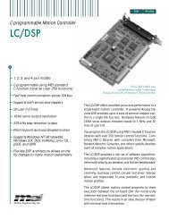
The following diagram illustrates the relationship between the different types of memory.<br />
RSTVAR<br />
SAVE<br />
Flash<br />
Stores Firmware and<br />
default parameter values<br />
RAM<br />
Stores run-time<br />
parameter values<br />
EEPROM<br />
Non-volatile memory for<br />
parameter values<br />
CLREEPROM<br />
LOAD<br />
CLREEPROM loads default values into RAM<br />
and clears non-volatile memory<br />
Figure 5-1: Drive Memory Architecture<br />
PicoDAD-SN <strong>User</strong> <strong>Manual</strong> Page 15 of 130
Danaher <strong>Motion</strong> Kollmorgen January 30, 2006<br />
6. Electrical Specifications<br />
6.1 Input Power<br />
Drive Model 10A 20A<br />
Main Input Power<br />
(both axes)<br />
Rated Output Power<br />
(Per Axis)<br />
Voltage (DC) Nominal ± 10%<br />
KVA<br />
Continuous current (Amps)<br />
Peak Current (Amps) for 500 msec<br />
Peak Current (Amps) for 2 sec<br />
Line fuses<br />
Continuous Power (VA) at 48VDC Input and<br />
45°C (113°F) Ambient<br />
Continuous Current (Arms)<br />
Peak Current (Arms) for 500 mSec<br />
Peak Current (Arms) for 2 Sec<br />
0.35<br />
10A for each<br />
axis<br />
10A for each<br />
axis<br />
10A for each<br />
axis<br />
48VDC<br />
PWM Frequency (kHz) PWM 16<br />
Motor Current Ripple (kHz) 32<br />
PWM Saturation 92.5% 1<br />
Logic Power +24 VDC Ext. Logic Voltage (volts) 22 to 27<br />
+24 VDC Ext. Logic Current (amps sink)<br />
6.2 Protection and Environment<br />
+24 VDC Ext. Logic Current (amps max inrush)<br />
10A for each<br />
axis<br />
20A for each<br />
axis<br />
TBD<br />
2A for 5msec, and then 1.5A<br />
for 7msec<br />
Under Voltage trip <strong>User</strong> programmable from 12 to 36VDC<br />
Protective Functions Over Voltage Trip 60VDC (FW versions up to and including 0.1.9)<br />
70VDC (FW versions above 0.1.9)<br />
Over Temperature Trip 80° C / 176° F<br />
Operating Temperature 5°C (41°F) to 45°C (113°F)<br />
Environment Storage Temperature 0°C (32°F) to 70°C (158°F)<br />
Ambient Humidity 10% to 90%<br />
1 PWM saturation affects the useable bus voltage. With a 48V input and with PWM saturation set to<br />
92.5%, the effective bus voltage is 44.4V. This affects the maximum achievable speed.<br />
PicoDAD-SN <strong>User</strong> <strong>Manual</strong> Page 16 of 130
Danaher <strong>Motion</strong> Kollmorgen January 30, 2006<br />
6.3 I/O<br />
Analog Inputs Maximum Voltage ±12.5 V differential<br />
Operating Voltage Range<br />
Input Resolution<br />
±10 V differential<br />
12 bit<br />
Sensitivity 6.1mV 2<br />
Input Impedance/CMR<br />
Frequency Response<br />
Accuracy<br />
Repeatability<br />
> 10 K ohms/50 dB<br />
LPF at 3.8Khz<br />
Bus Voltage Measurement Filtering LPF at 3Hz<br />
Drive Temperature Measurement Filtering LPF at 1.5kHz<br />
General Purpose Digital Inputs<br />
Over-Travel and Home<br />
Remote Enable<br />
General Purpose Digital Outputs<br />
Input circuit characteristic<br />
Input voltage<br />
Maximum current<br />
Delay<br />
Output circuit characteristic<br />
Maximum load capacity<br />
Maximum saturated voltage<br />
Opto-coupler<br />
5-24Vdc<br />
Fast Inputs Input Signal Characteristic RS422<br />
Maximum frequency<br />
10mA per input<br />
Opto-coupler; open<br />
collector, common<br />
emitter, Sink<br />
configuration<br />
24Vdc / 60mA<br />
2V<br />
2.5MHz<br />
Fast Outputs Output format RS422<br />
Maximum frequency<br />
2.5MHz<br />
2<br />
25V(full span)/4096 (12 bit)<br />
PicoDAD-SN <strong>User</strong> <strong>Manual</strong> Page 17 of 130
Danaher <strong>Motion</strong> Kollmorgen January 30, 2006<br />
6.4 Encoder Feedback<br />
Encoder power<br />
supply<br />
Quadrature Encoder<br />
Encoder supply Voltage<br />
Encoder supply current<br />
Signal Characteristics<br />
A/B<br />
Index<br />
Halls<br />
Maximum quadrature input frequency<br />
5VDC<br />
300mA for each encoder interface<br />
Differential RS422<br />
Differential RS422<br />
Differential, single-ended or opencollector<br />
3MHz (before quadrature)<br />
Sine Encoder<br />
Signal Characteristics<br />
A/B<br />
Index<br />
Halls<br />
EnDat<br />
Maximum sine encoder input<br />
frequency<br />
Interpolation<br />
Differential, 1Vp-p @ 2.5V offset<br />
Differential 1Vp-p or RS422<br />
Differential, single-ended or opencollector<br />
RS422 data + clock<br />
-3dB at 265kHz<br />
Set by a drive parameter (MSININT)<br />
Maximum value is x512 before<br />
quadrature.<br />
Equivalent resolution in counts per rev<br />
is<br />
MENCRES * MSININT * 4<br />
Note: The quadrature encoder must have differential RS-422 A, B, Z signals. The<br />
PicoDAD will not work with single-ended TTL feedback signals.<br />
PicoDAD-SN <strong>User</strong> <strong>Manual</strong> Page 18 of 130
Danaher <strong>Motion</strong> Kollmorgen January 30, 2006<br />
6.5 Resolver<br />
The PicoDAD can use single-speed (two-pole) resolver feedback to monitor the motor shaft position. A<br />
resolver can be thought of as a transformer whose output is unique for any given shaft position (an<br />
absolute position feedback). The transformer is driven with a sine wave reference signal. Two AC signals<br />
are returned from the resolver into the Sine and Cosine inputs.<br />
Type<br />
Transformation Ratio<br />
Modulation Frequency<br />
Input Voltage (From Drive)<br />
Max DC Resistance<br />
Max Drive Current<br />
Output Voltage (To Drive)<br />
Accuracy<br />
Repeatability<br />
ResBW = 300<br />
ResBW = 600<br />
ResBW = 300<br />
ResBW = 600<br />
Single-pole<br />
0.4 to 0.6 (dependant on the Resolver itself)<br />
8kHz<br />
TBD ArcMin<br />
TBD ArcMin<br />
TBD ArcMin<br />
TBD ArcMin<br />
PicoDAD-SN <strong>User</strong> <strong>Manual</strong> Page 19 of 130
Danaher <strong>Motion</strong> Kollmorgen January 30, 2006<br />
7. Mounting<br />
The PicoDAD-SN is designed for book mounting. This panel assembly is then mounted in a metallic<br />
enclosure. Enclosures are supplied by the manufacturers of the final product and meet the environmental<br />
IP rating of the end product. To ensure proper grounding (and to optimize EMC), the enclosure should<br />
have continuous ground continuity maintained between all metal panels. This ground continuity is intended<br />
to be both a safety ground and a high frequency ground.<br />
The units are mounted on a backplane installed into the enclosure. Ideally, the backplane should be an<br />
unpainted metallic surface to optimize electrical bonding of the frame and provide the lowest possible<br />
impedance path to earth ground. These enclosures also provide added safety.<br />
Particular care should be used when layout of an enclosure is designed. Separate power wires from small<br />
signal wires. The following guide<strong>line</strong>s highlight some important wiring practices to implement:<br />
• Control and signal cables must be separated from power and motor cables. Distance of 20 cm (8<br />
in.) is sufficient in most cases.<br />
• Control and signal cables must be shielded to reduce the effects of radiated interference.<br />
• When control cables must cross power or motor cables, they should cross at an angle of 90°, if<br />
possible. This reduces the field coupling effect<br />
7.1 Hardware Specifications<br />
7.2 Out<strong>line</strong> Dimensions<br />
163.2 (Height) x 71.5 (Width) x 116.3 (Depth) mm. (6.44” x 2.81” x 4.58”)<br />
The Height dimensions specified here do not include the mounting flange.<br />
PicoDAD-SN <strong>User</strong> <strong>Manual</strong> Page 20 of 130
Danaher <strong>Motion</strong> Kollmorgen January 30, 2006<br />
7.2.1 Front View<br />
7.2.2 Side View<br />
PicoDAD-SN <strong>User</strong> <strong>Manual</strong> Page 21 of 130
Danaher <strong>Motion</strong> Kollmorgen January 30, 2006<br />
7.3 Mounting Alignment<br />
The drive must be vertically mounted, to allow for convection cooling.<br />
At least 1cm of space must be left between adjacent drives<br />
PicoDAD-SN <strong>User</strong> <strong>Manual</strong> Page 22 of 130
Danaher <strong>Motion</strong> Kollmorgen January 30, 2006<br />
8. Wiring<br />
8.1 Wiring Diagram<br />
M<br />
M<br />
Chassis<br />
Phase C<br />
Phase B<br />
Phase A<br />
Chassis<br />
Phase C<br />
Phase B<br />
Phase A<br />
Pico DAD<br />
8 8<br />
Motor 0<br />
Motor 1<br />
M0 Feedback<br />
M1 Feedback<br />
1<br />
2<br />
3<br />
4<br />
5<br />
6<br />
7<br />
8<br />
9<br />
10<br />
1<br />
2<br />
3<br />
4<br />
5<br />
6<br />
7<br />
8<br />
9<br />
10<br />
11<br />
12<br />
13<br />
14<br />
15<br />
16<br />
17<br />
18<br />
19<br />
20<br />
11<br />
12<br />
13<br />
14<br />
15<br />
16<br />
17<br />
18<br />
19<br />
20<br />
Machine I/O<br />
Control I/O<br />
14<br />
15<br />
26<br />
27<br />
1<br />
2<br />
1<br />
2<br />
Axis 2 Common<br />
Axis 2 CW<br />
Axis 2 Home<br />
Axis 2 CCW<br />
Axis 1 Common<br />
Axis 1 CW<br />
Axis 1 CCW<br />
Axis 1 Home<br />
In Common 1<br />
In 1<br />
In 2<br />
In 3<br />
In 4<br />
In Common 2<br />
In 5<br />
In 6<br />
In 7<br />
In 8<br />
Out Common<br />
Out 1<br />
Load<br />
Out 2<br />
Load<br />
Out 3<br />
Load<br />
Out 4<br />
Load<br />
Fault Relay<br />
5V<br />
5V<br />
Brake Relay x 2<br />
-<br />
+<br />
A<br />
B<br />
A<br />
B<br />
Power<br />
supply<br />
(5 -24V)<br />
Power<br />
supply<br />
(5 -24V)<br />
Power<br />
supply<br />
(5 -24V)<br />
In Common 3<br />
Axis 1 Enable<br />
Power<br />
Axis 2 Enable<br />
supply<br />
(5 -24V)<br />
Fast Out #1<br />
Fast Out #2<br />
Fast Out #3<br />
Fast Out #4<br />
Fast Out #5<br />
Fast Out #6<br />
Fast In #1<br />
Fast In #2<br />
Fast In #3 Fast In #4<br />
I<br />
Power<br />
supply<br />
(5-24V)<br />
Power<br />
supply<br />
(5-24V)<br />
Secondary Encoder #1<br />
RS-422<br />
Secondary Encoder #2<br />
RS-422<br />
Brake Relay<br />
24VDC<br />
Fast Outputs<br />
RS -422<br />
Fast Inputs<br />
RS -422<br />
NOTE: Refer to the Macine I/O<br />
Connector pin-out for pin<br />
numbers<br />
NOTE: Refer to the Control I/O<br />
Connector pin-out for pin<br />
numbers<br />
Analog Inputs<br />
Power<br />
supply<br />
48V<br />
+<br />
-<br />
Bus In (48V)<br />
Bus IN (48 V)<br />
1<br />
2<br />
+<br />
l<br />
48 V IN<br />
48 V RTN<br />
SynqNet RJ-45<br />
24 V<br />
24V In<br />
+<br />
-<br />
Power<br />
supply<br />
24V<br />
PE<br />
PicoDAD-SN <strong>User</strong> <strong>Manual</strong> Page 23 of 130
Danaher <strong>Motion</strong> Kollmorgen January 30, 2006<br />
8.2 Connector Pin-Outs<br />
8.2.1 Logic Power<br />
Connector Definition<br />
Manufacturer<br />
Part Number<br />
Mating Connector Part Number<br />
Phoenix Contact<br />
MSTB 2,5/2-GF-5,08<br />
MSTBT 2,5/ 2-STF-5,08<br />
Pin Out<br />
Pin # Description Comments<br />
1 Logic Power<br />
2 Logic Power return Refer to Grounding Tree<br />
8.2.2 Bus Power<br />
Connector Definition<br />
Manufacturer<br />
Molex<br />
Part Number 42820-2212<br />
Mating Connector Part Number<br />
42816-0212 (Housing)<br />
42815-0011 (Pins)<br />
63813-0500 (<strong>Manual</strong> Extraction Tool)<br />
Pin Out<br />
Pin # Description Comments<br />
1 Bus Power<br />
2 Bus Power return Refer to Grounding Tree<br />
PicoDAD-SN <strong>User</strong> <strong>Manual</strong> Page 24 of 130
Danaher <strong>Motion</strong> Kollmorgen January 30, 2006<br />
8.2.3 Motor Power<br />
Connector Definition<br />
Manufacturer<br />
Molex<br />
Part Number 43160-3104<br />
Mating Connector Part Number<br />
44441-2004 (Housing)<br />
43375-0001 (Pins)<br />
63813-0500 (<strong>Manual</strong> Extraction Tool)<br />
Pin Out<br />
Pin # Description Comments<br />
1 Chassis Refer to Grounding Tree<br />
2 Phase C<br />
3 Phase B<br />
4 Phase A<br />
8.2.4 Feedback<br />
8.2.4.1 Connector Definition<br />
Manufacturer<br />
Connectors from any of the following manufacturers<br />
are used: 3M; ACON; Hirose<br />
Part Number 3M N10220-52B2VC<br />
ACON HBR20-20K3211<br />
Hirose DX106GM-20SE<br />
Mating Connector Part Number 3M Connector: 10120-6000EC<br />
Housing: 10320-3210-00<br />
Cable: 3M 3444C-10P<br />
8.2.4.2 Connector Pin Arrangement<br />
Pin #2<br />
Pin #1<br />
Pin #20<br />
Pin#11<br />
PicoDAD-SN <strong>User</strong> <strong>Manual</strong> Page 25 of 130
Danaher <strong>Motion</strong> Kollmorgen January 30, 2006<br />
8.2.4.3 Pin Out<br />
Pin #<br />
Incremental<br />
Encoder<br />
Resolver<br />
Sine Encoder<br />
EnDat<br />
Sine Encoder<br />
C/D<br />
1 E5V E5V E5V E5V<br />
2 E5V E5V E5V E5V<br />
3 A Sine A A<br />
4 A\ Sine\ A\ A\<br />
5 Z Ref<br />
6 Z\ Ref\<br />
7 Hall1 SSI Data C<br />
8 Hall1\ SSI Data\ C\<br />
9 Hall3<br />
10 Hall3\<br />
11 DGND DGND DGND DGND<br />
12 DGND DGND DGND DGND<br />
13 B Cosine B B<br />
14 B\ Cosine\ B\ B\<br />
15 DGND DGND DGND DGND<br />
16 DGND DGND DGND DGND<br />
17 Hall2 SSI Clock D<br />
18 Hall2\ SSI Clock\ D\<br />
19 Motor temp Motor temp Motor temp Motor temp<br />
20 Motor temp rtn Motor temp rtn Motor temp rtn Motor temp rtn<br />
8.2.5 Machine I/O<br />
8.2.5.1 Connector Definition<br />
Manufacturer<br />
Connectors from any of the following manufacturers are<br />
used:<br />
3M; ACON; Hirose<br />
Part Number 3M N10226-52B2VC<br />
ACON HBR26-20K3211<br />
Hirose DX106GM-26SE<br />
Mating Connector Part Number 3M Connector: 10126-6000EC<br />
Housing: 10326-3210-00<br />
Cable: 3M 3444C-13P<br />
PicoDAD-SN <strong>User</strong> <strong>Manual</strong> Page 26 of 130
Danaher <strong>Motion</strong> Kollmorgen January 30, 2006<br />
8.2.5.2 Connector Pin Arrangement<br />
Pin #2<br />
Pin #1<br />
Pin #26<br />
Pin #14<br />
8.2.5.3 Pin Out<br />
Pin # Description Comments<br />
1 Common for Axis 1 inputs Common for CW, CCW and Home<br />
2 Axis 1 negative limit Opto input; 5-24V; Wired to SynqNet FPGA<br />
Referenced to Common on pin #1<br />
3 Axis 1 secondary encoder B signal<br />
4 Axis 1 secondary encoder B-complement signal<br />
5 Axis 1 secondary encoder A signal<br />
6 Axis 1 secondary encoder A-complement signal<br />
RS-422 input<br />
RS-422 input<br />
7 Axis 2 positive limit Opto input; 5-24V; Wired to SynqNet FPGA<br />
Referenced to Common on pin #20<br />
8 Axis 2 home signal Opto input; 5-24V; Wired to SynqNet FPGA<br />
Referenced to Common on pin #20<br />
9 Axis 2 negative limit Opto input; 5-24V; Wired to SynqNet FPGA<br />
Referenced to Common on pin #20<br />
10 Axis 2 secondary encoder Index signal<br />
11 Axis 2 secondary encoder Index-complement<br />
signal<br />
12 Axis 2 brake+ contact<br />
13 Axis 2 brake- contact<br />
RS-422 input; wired to SynqNet FPGA<br />
Dry contact relay; controlled by SynqNet FPGA.<br />
Note polarization<br />
14 Axis 1 positive limit Opto input; 5-24V; Wired to SynqNet FPGA<br />
Referenced to Common on pin #1<br />
15 5VDC supply to secondary encoder Fuse-protected; resettable fuse<br />
16 Axis 1 home signal Opto input; 5-24V; Wired to SynqNet FPGA<br />
Referenced to Common on pin #1<br />
17 Ground for secondary encoder power Connected to Digital Ground in the drive<br />
PicoDAD-SN <strong>User</strong> <strong>Manual</strong> Page 27 of 130
Danaher <strong>Motion</strong> Kollmorgen January 30, 2006<br />
Pin # Description Comments<br />
18 Axis 1 brake+ contact<br />
Dry contact relay; controlled by SynqNet FPGA.<br />
19 Axis 1 brake- contact<br />
Note polarization<br />
20 Common for Axis 2 inputs Common for CW, CCW and Home<br />
21 Axis 2 secondary encoder B-complement signal<br />
22 Axis 2 secondary encoder B signal<br />
RS-422 input; wired to SynqNet FPGA<br />
23 Ground for secondary encoder power Connected to Digital Ground in the drive<br />
24 Axis 2 secondary encoder A-complement signal RS-422 input (with pin 26); wired to SynqNet<br />
FPGA<br />
25 5VDC supply to secondary encoder Fuse-protected; resettable fuse<br />
26 Axis 2 secondary encoder A signal RS-422 input (with pin 24); wired to SynqNet<br />
FPGA<br />
8.2.6 Controller I/O<br />
8.2.6.1 Connector Definition<br />
Manufacturer<br />
Connectors from any of the following<br />
manufacturers are used:<br />
3M; ACON; Hirose<br />
Part Number 3M N10250-52B2VC<br />
ACON HBR50-20K3211<br />
Hirose DX106GM-50SE<br />
Mating Connector Part Number 3M Connector 10150-6000EC<br />
Housing 10350-A200-00<br />
Cable: 3M 3444C-25P<br />
8.2.6.2 Connector Pin Arrangement<br />
Pin #2<br />
Pin #1<br />
Pin #50<br />
Pin #26<br />
8.2.6.3 Pin Out<br />
Pin # Description Comments<br />
1 Common for Opto-isolated Inputs 1, 2, 3, 4<br />
2 Motor 0, OPTO IN2 Referenced to Common on pin #1<br />
3 Motor 0, OPTO IN1 Referenced to Common on pin #1<br />
PicoDAD-SN <strong>User</strong> <strong>Manual</strong> Page 28 of 130
Danaher <strong>Motion</strong> Kollmorgen January 30, 2006<br />
Pin # Description Comments<br />
4 Motor 1, OPTO IN2 Referenced to Common on pin #30<br />
5 Motor 1, OPTO IN1 Referenced to Common on pin #30<br />
6 Motor 1, REMOTE ENABLE Referenced to Common on pin #33<br />
7 Motor 0, REMOTE ENABLE Referenced to Common on pin #33<br />
8 Common for Opto-isolated Outputs 1, 2, 3, 4<br />
9 Motor 1, OPTO OUT1 Referenced to Common on pin #8<br />
10 Motor 1, OPTO OUT0 Referenced to Common on pin #8<br />
11 Motor 0, RS422 OUT3<br />
12 Motor 0, RS422 OUT3 Complement<br />
RS-422 output; wired to SynqNet FPGA<br />
13 Motor 0, RS422 OUT2<br />
14 Motor 0, RS422 OUT2 Complement<br />
RS-422 output; wired to SynqNet FPGA<br />
15 Motor 1, RS422 OUT1 Complement<br />
16 Motor 1, RS422 OUT1<br />
RS-422 output; wired to SynqNet FPGA<br />
17 Motor 0, RS422 IN2<br />
18 Motor 0, RS422 IN2 Complement<br />
RS-422 input; wired to SynqNet FPGA<br />
19 Motor 0, RS422 IN1<br />
20 Motor 0, RS422 IN1 Complement<br />
RS-422 input; wired to SynqNet FPGA<br />
21 Analog Ground<br />
Reference ground for Axis 1 analog inputs. This<br />
pin should be connected to the ground of the<br />
analog command source.<br />
22 Analog Ground<br />
Reference ground for Axis 2 analog inputs. This<br />
pin should be connected to the ground of the<br />
analog command source.<br />
23 Axis 1 Analog Input #2<br />
24 Axis 1 Analog Input #2 Complement<br />
Differential analog Input; ±10Vdc<br />
25 Axis 2 Analog Input #2<br />
Differential analog Input; ±10Vdc. Paired with<br />
pin #50<br />
26 Fault Relay Terminal #1<br />
Dry contact relay. Polarity of wiring is not<br />
27 Fault Relay Terminal #2<br />
constrained<br />
28 Motor 0, OPTO IN4 Referenced to Common on pin #1<br />
29 Motor 0, OPTO IN3 Referenced to Common on pin #1<br />
30 Common for Opto-isolated Inputs 5, 6, 7, 8<br />
31 Motor 1, OPTO IN4 Referenced to Common on pin #30<br />
32 Motor 1, OPTO IN3 Referenced to Common on pin #30<br />
33 Common for Remote Enable Inputs<br />
34 Motor 0, OPTO OUT1 Referenced to Common on pin #8<br />
35 Motor 0, OPTO OUT0 Referenced to Common on pin #8<br />
36 Motor 0, RS422 OUT1 Complement<br />
37 Motor 0, RS422 OUT1<br />
RS-422 output; wired to SynqNet FPGA<br />
38 Motor 1, RS422 OUT2<br />
39 Motor 1, RS422 OUT2 Complement<br />
RS-422 output; wired to SynqNet FPGA<br />
40 Motor 1, RS422 OUT3 Complement<br />
41 Motor 1, RS422 OUT3<br />
RS-422 output; wired to SynqNet FPGA<br />
PicoDAD-SN <strong>User</strong> <strong>Manual</strong> Page 29 of 130
Danaher <strong>Motion</strong> Kollmorgen January 30, 2006<br />
Pin # Description Comments<br />
42 Motor 1, RS422 IN1 Complement<br />
43 Motor 1, RS422 IN1<br />
44 Motor 1, RS422 IN2 Complement<br />
45 Motor 1, RS422 IN2<br />
46 Axis 1 Analog Input #1<br />
47 Axis 1 Analog Input #1 Complement<br />
48 Axis 2 Analog Input #1<br />
49 Axis 2 Analog Input #1 Complement<br />
50 Axis 2 Analog Input #2 complement<br />
RS-422 input; wired to SynqNet FPGA<br />
RS-422 input; wired to SynqNet FPGA<br />
Differential analog Input; ±10Vdc<br />
Differential analog Input; ±10Vdc<br />
Differential analog Input; ±10Vdc. Paired with<br />
pin #25<br />
8.2.7 SynqNet<br />
Connector Definition<br />
Connector Type<br />
RJ-45<br />
Manufacturer<br />
Molex<br />
Part Number 85505-0001<br />
Mating Connector Part Number<br />
Mates with industry standard FCC 68 plugs<br />
Pin Out<br />
Pin # IN OUT<br />
1 TD0+ RD0+<br />
2 TD0- RD0-<br />
3 RD0+ TD0+<br />
4 TTERM0 RTERM1<br />
5 TTERM1 RTERM1<br />
6 RD0- TD0-<br />
7 RTERM0 TTERM1<br />
8 RTERM1 TTERM1<br />
8.2.8 RS-232<br />
Connector Definition<br />
Connector Type<br />
Male 9 pin D-Sub<br />
Manufacturer<br />
e-tec<br />
Part Number<br />
SSM-009-U908-02/R<br />
Mating Connector Part Number<br />
Pin Out<br />
Pin # Description Comments<br />
1 NC<br />
2 Rx RS-232 Receive<br />
3 Tx RS-232 Transmit<br />
4 NC<br />
5 DGND Ground. Used for Hardware Ember<br />
PicoDAD-SN <strong>User</strong> <strong>Manual</strong> Page 30 of 130
Danaher <strong>Motion</strong> Kollmorgen January 30, 2006<br />
6 NC<br />
7 HW Ember Used for Hardware Ember<br />
8 BRXD Daisy chain Receive<br />
9 BTXD Daisy chain Transmit<br />
Note: The RS-232 cable between a computer or terminal and the PicoDAD must<br />
have only pins 2, 3 and 5 connected.<br />
8.3 Wiring a Motor to the Drive<br />
8.3.1 Kollmorgen AKM Motors<br />
The motor phases and feedback signals must be wired as described in the following tables. In addition, set<br />
drive parameter MOTORTYPE to the value '3'.<br />
Motor Phases<br />
Historically Kollmorgen motor phases have been designated with the letters 'A', 'B', and 'C' for each of the<br />
3 phase connections. The AKM motors are labeled 'U', 'V', and 'W'. The relationship of these signals is<br />
shown in the following table:<br />
Motor Phase Wire Color Drive Phase<br />
U BLUE C<br />
V BROWN B<br />
W VIOLET A<br />
Commutation Track Signals (for the encoder motor):<br />
Motor Signal Name Drive feedback signal name Drive feedback pin number<br />
U HALL3 9<br />
U\ HALLS3\ 10<br />
V HALL2 17<br />
V\ HALL2\ 18<br />
W HALL1 7<br />
W\ HALL1\ 8<br />
Wiring of the commutation track signal complements is optional; for improved noise immunity it is<br />
recommended to connect them.<br />
Encoder Feedback Signals<br />
Motor Signal Name Wire Color Drive feedback signal name Drive feedback pin number<br />
A BLUE B 13<br />
A\ BLUE/BLK B\ 14<br />
B GREEN A 3<br />
B\ GRN/BLK A\ 4<br />
Z VIOLET Z 5<br />
Z\ VIOLET/BLK Z\ 6<br />
PicoDAD-SN <strong>User</strong> <strong>Manual</strong> Page 31 of 130
Danaher <strong>Motion</strong> Kollmorgen January 30, 2006<br />
Resolver Feedback Signals<br />
Motor Signal Name Wire Color Drive feedback signal name Drive feedback pin number<br />
S1, SIN+ RED Cosine 13<br />
S3, SIN- BLACK Cosine\ 14<br />
S2, COS+ YELLOW Sine\ 4<br />
S4, COS- BLUE Sine 3<br />
R1, REF+ RED/WHT Ref\ 6<br />
R2, REF- BLK/WHT Ref 5<br />
8.4 Connector Kit<br />
A connector / integration kit is available. This kit contains mating connectors and crimp pins for the power<br />
connectors, and cables with MDR connectors on the one end and flying leads on the other for the<br />
feedback and I/O connectors. The part number for this kit is<br />
CON-KIT-STX-2<br />
The exact contents of the kit are as follows:<br />
Item Description<br />
Quantity<br />
Motors feedback cables 2<br />
26-pin Machine I/O cable 1<br />
50-pin Control I/O cable 1<br />
Bus power (48V) connector 1<br />
Logic power (24V) connector 1<br />
Motors power connectors 2<br />
Crimp pins for motor power connector 8<br />
Crimp pins for bus power connector 2<br />
This connector kit is available from the Danaher <strong>Motion</strong> facility of Kollmorgen Servotronix only.<br />
PicoDAD-SN <strong>User</strong> <strong>Manual</strong> Page 32 of 130
Danaher <strong>Motion</strong> Kollmorgen January 30, 2006<br />
8.5 Grounding Tree<br />
PicoDAD Ground tree<br />
3.3V<br />
3.3VA<br />
DC/DC<br />
5V<br />
DC/DC<br />
24V<br />
Filter<br />
+<br />
-<br />
Logic Power Supply<br />
24V<br />
Single Ground plane<br />
Power Digital<br />
GND<br />
15V<br />
DC/DC<br />
GND<br />
Connected to spacer<br />
Motor<br />
S S D<br />
D<br />
G<br />
G<br />
FET Driver<br />
GND<br />
GND<br />
+48V<br />
-<br />
Bus Power Supply<br />
Connected to heat sink<br />
GND<br />
8.6 Electrical Interfaces<br />
8.6.1 Over-Travel Limits and Home<br />
Mx_Common<br />
3V3<br />
1<br />
4<br />
4.7KR<br />
to FPGA<br />
Mx_in<br />
2.4K/250mW<br />
10K<br />
330pF<br />
2<br />
3<br />
DGND<br />
3V3<br />
1<br />
4<br />
4.7KR<br />
to FPGA<br />
Mx_in<br />
2.4K/250mW<br />
10K<br />
330pF<br />
2<br />
3<br />
DGND<br />
PicoDAD-SN <strong>User</strong> <strong>Manual</strong> Page 33 of 130
Danaher <strong>Motion</strong> Kollmorgen January 30, 2006<br />
8.6.2 Remote Enable<br />
3V3<br />
In_Common x<br />
Ena_M0<br />
2.4K/250mW<br />
10KR<br />
330pF<br />
1<br />
2<br />
4<br />
3<br />
10KR<br />
DGND<br />
3V3<br />
to FPGA / DSP<br />
Ena_M1<br />
2.4K/250mW<br />
10KR<br />
330pF<br />
1<br />
2<br />
4<br />
3<br />
10KR<br />
DGND<br />
to FPGA / DSP<br />
8.6.3 General-Purpose Inputs<br />
3V3<br />
In_Common x<br />
In X<br />
2.4K/250mW<br />
10KR<br />
330pF<br />
1<br />
2<br />
4<br />
3<br />
10KR<br />
DGND<br />
3V3<br />
to FPGA<br />
In X<br />
2.4K/250mW<br />
10KR<br />
330pF<br />
1<br />
2<br />
4<br />
3<br />
10KR<br />
DGND<br />
to FPGA<br />
8.6.4 General-Purpose Outputs<br />
Out x<br />
28V 1<br />
4<br />
150R<br />
From FPGA<br />
Out_Common<br />
3<br />
2<br />
DGND<br />
PicoDAD-SN <strong>User</strong> <strong>Manual</strong> Page 34 of 130
Danaher <strong>Motion</strong> Kollmorgen January 30, 2006<br />
8.6.5 High Speed Inputs<br />
Fast In<br />
150R<br />
Fast In\<br />
VCC<br />
VCC<br />
1KR<br />
2<br />
1<br />
4<br />
12<br />
IN+<br />
IN-<br />
CON<br />
CON<br />
OUT<br />
3<br />
To FPGA<br />
8.6.6 High Speed Outputs<br />
Fast Out<br />
Fast Out\<br />
150R<br />
14<br />
13<br />
OUT<br />
OUT<br />
IN 15<br />
From FPGA<br />
EN 4<br />
100R<br />
EN 12 VCC<br />
VCC<br />
8.6.7 Analog Inputs<br />
The Analog inputs are differential, but the common mode is limited. The AGND pin should be connected to<br />
the ground of the analog command source.<br />
GND<br />
1 8<br />
2.4K<br />
GND<br />
4.7nF<br />
4<br />
Ain_p<br />
Ain_n<br />
7<br />
6<br />
2<br />
10.0K<br />
3<br />
10.0K<br />
8<br />
5<br />
1<br />
10.0K<br />
4<br />
10.0K<br />
7<br />
2<br />
3<br />
-<br />
+<br />
1<br />
To DSP ADC<br />
8<br />
4.7nF<br />
GND<br />
2<br />
2.4K<br />
VCC<br />
Reference voltage<br />
PicoDAD-SN <strong>User</strong> <strong>Manual</strong> Page 35 of 130
Danaher <strong>Motion</strong> Kollmorgen January 30, 2006<br />
8.6.8 Fault Relay<br />
RLY_C<br />
RLY_NO<br />
2<br />
4<br />
3<br />
VCC<br />
9<br />
7<br />
+<br />
-<br />
8<br />
1<br />
10<br />
470R<br />
flt_relay (FPGA)<br />
4.7KR<br />
DGND<br />
DGND<br />
8.6.9 Brake Relay<br />
From FPGA<br />
470R<br />
VCC<br />
3<br />
8<br />
1<br />
10<br />
+<br />
-<br />
2<br />
4<br />
9<br />
7<br />
26V<br />
1.1A resetable<br />
Brake1<br />
Brake2<br />
DGND<br />
8.6.10 Sine Encoder<br />
8.6.11 Halls<br />
8.6.12 Quadrature Encoder<br />
PicoDAD-SN <strong>User</strong> <strong>Manual</strong> Page 36 of 130
Danaher <strong>Motion</strong> Kollmorgen January 30, 2006<br />
9. System Operation<br />
9.1 Powering Up<br />
<strong>On</strong>e of the characteristics of SynqNet drives is that at power up, the drive DSP is held in a RESET state<br />
by the SynqNet FPGA in the drive. The DSP reset is only released when a SynqNet RESET command is<br />
issued from the controller. <strong>On</strong>ce this is done, the drive will come up.<br />
The SynqNet RESET can be done in two ways:<br />
• Using <strong>Motion</strong>Console: Click on the RESET button in the Controller Summary window (on the<br />
ACTIONS tab)<br />
• Using a DOS command:<br />
o<br />
o<br />
Open a DOS PROMPT window in the * XMP\ Bin\ WinNT folder<br />
Type RESET at the command prompt<br />
9.2 SynqNet Utilities<br />
A set of SynqNet utilities is installed in the *\XMP\BIN\WINNT folder. These utilities can be used to<br />
perform many drive configuration operations over SynqNet. This manual references many of these utilities,<br />
but provides, for the purposes of legibility, only an abbreviated description of their syntax. The complete<br />
syntax is found on the <strong>Motion</strong> <strong>Engineering</strong> support web site, at http://support.motioneng.com/. Reference<br />
should be made to the web site for complete syntax information.<br />
9.3 Rotary Switch Configuration<br />
The PicoDAD is equipped with a 16-pole rotary switch, accessible from the top of the unit. The switch has<br />
no functional use for either the drive or the network. It can be used at the application level to identify<br />
specific nodes on a network.<br />
Caution: The switch must be set to a non-zero value. Setting it to zero causes the<br />
SynqNet RESET to be bypassed, and the drive will not function correctly on the<br />
SynqNet network.<br />
9.4 Current Scaling<br />
The torque command from the controller is multiplied by 0.8 in the drive, and resultant value is used as the<br />
torque command within the drive. That is:<br />
Drive internal torque command = Controller torque command * 0.8<br />
The reasoning is as follows:<br />
The torque command from the motion controller is a value in the range –32768 to +32767, while currents<br />
in the drive are referenced to the drive peak current, DIPEAK.<br />
While DIPEAK represents the absolute maximum current that can be commanded by the drive, the drive is<br />
designed to be able measure actual current 25% above DIPEAK. This is done in order to be able to<br />
measure, and control, current overshoots. Thus, the maximum current that can be represented in the drive<br />
is DIPEAK*1.25.<br />
The torque command from the motion controller must be scaled to the maximum current that the drive can<br />
represent, which is DIPEAK*1.25. However, the controller should not be able to command current above<br />
DIPEAK. Thus, the torque command from the controller is multiplied by 0.8.<br />
PicoDAD-SN <strong>User</strong> <strong>Manual</strong> Page 37 of 130
Danaher <strong>Motion</strong> Kollmorgen January 30, 2006<br />
A full-scale torque command of 32767 is thus interpreted in the drive as 26213, and this value is<br />
equivalent to DIPEAK, as shown in the following diagram.<br />
Controller current<br />
command (DAC output)<br />
32767<br />
Drive current<br />
command<br />
32767 = 1.25*DIPEAK<br />
32767*0.8 = DIPEAK<br />
To allow current<br />
feedback overshoot<br />
-32767*0.8 = -DIPEAK<br />
-32767<br />
-32767 = -1.25*DIPEAK<br />
Figure 9-1: Current Scaling<br />
9.5 PWM Saturation<br />
The PWM saturation level is 92.5%. This affects the useable bus voltage. With a 48V input and with PWM<br />
saturation set to 92.5%, the effective bus voltage is 44.4V. This affects the maximum achievable speed.<br />
9.6 Drive Parameters<br />
The drive functionality is set using various drive parameters and instructions, which are communicated<br />
over SynqNet. Parameters may be subject to read-only access, or may be available for read/write access.<br />
The parameters can be stored in non-volatile memory in the drive, to be used on each power-up.<br />
Examples of read-only parameters are: amplifier current rating, absolute current limit, and analog input<br />
values. Examples of read/write drive parameters are: motor current rating, application current limit and<br />
encoder resolution.<br />
Drives are shipped from the factory with motor parameters set to zero and application parameters set to<br />
their default values.<br />
Parameters are identified both by their mnemonics and by an index. It is the index that is used when<br />
accessing a parameter over SynqNet. A list of parameters appears in Section titled Instruction Set.<br />
Drive parameters are implemented for particular drive models and firmware versions; the supported<br />
parameter set may be different for different version of firmware.<br />
The MPI library contains a general drive parameter interface, able to handle any set of drive parameters,<br />
independent of the MPI library version. It uses a drive parameter map file to determine the valid drive<br />
parameters. Individual drive parameters can be set (or read) using MPI methods or the sqDriveParam<br />
utility program. A list of drive parameters can be set (or read) using MPI methods or the sqDriveConfig<br />
utility program.<br />
PicoDAD-SN <strong>User</strong> <strong>Manual</strong> Page 38 of 130
Danaher <strong>Motion</strong> Kollmorgen January 30, 2006<br />
The following sections describe the syntax of utilities used when accessing parameters. These utilities are<br />
typically executed from a DOS window in the XMP\BIN\WINNT directory. For application programming<br />
methods, please refer to the <strong>Motion</strong> <strong>Engineering</strong> support website: http://support.motioneng.com.<br />
9.6.1 Memory Operations on Drive Parameters<br />
As described in the section on the Drive Processor Memory Description, the drive firmware runs using<br />
parameters stored in RAM. These parameters can, however, be saved in non-volatile memory (E 2 PROM),<br />
from where they would be loaded into RAM upon power up. The non-volatile memory can also be cleared.<br />
Parameters may be reset to their default values, and a set of saved parameters may be loaded from the<br />
non-volatile memory into the RAM.<br />
The operations described above are executed using SynqNet Direct Commands. The following table<br />
summarizes these commands. The command mnemonic serves to identify the specific command. It also<br />
indicates the syntax of the command used when communicating with the drive over the serial port.<br />
Description<br />
Command<br />
Mnemonic<br />
SynqNet Direct<br />
Command<br />
Notes<br />
Save Parameters SAVE 0x1C Save all parameters to nonvolatile<br />
memory<br />
Clear non-volatile<br />
memory<br />
Reset parameters to<br />
default<br />
Load parameters from<br />
memory<br />
CLREEPROM 0x1F Clear contents of non-volatile<br />
memory. CLREEPROM sets all<br />
parameters to their default<br />
values, and sets motor<br />
parameters to the value zero<br />
RSTVAR 0x1D Reset application parameters to<br />
their default values. This<br />
command does not affect motor<br />
parameters<br />
LOAD 0x1E Load a set of saved parameters<br />
from non-volatile memory.<br />
Both the CLREEPROM command (Direct Command 0x1F) and the RSTVAR command (Direct Command<br />
0x1D) return parameters to their default values. The difference, however, is that RSTVAR does not affect<br />
motor or current limit parameters. The specific parameters not affected by RSTVAR are:<br />
Motor Parameters<br />
MIPEAK, MICONT, MPITCH, MOTORTYPE, MSPEED, MKT, MBEMF, MENCRES, MSININT,<br />
MENCTYPE, MENCOFF, MPHASE, MPOLES, MBEMFCOMP, MLMIN, MLGAINC, MLGAINP,<br />
MTANGLC, MTANGLP, MVANGLH, MVANGLF<br />
Current Limit Parameters<br />
ILIM, ICONT<br />
Foldback Parameters<br />
FOLDD, FOLDR, FOLDT<br />
9.6.2 Accessing Individual Parameters<br />
Use the sqDriveParam utility for accessing individual parameters. For the syntax below the following<br />
conventions hold:<br />
PicoDAD-SN <strong>User</strong> <strong>Manual</strong> Page 39 of 130
Danaher <strong>Motion</strong> Kollmorgen January 30, 2006<br />
x is the node number. Nodes are numbered from 0.<br />
y is the drive, or axis, number on that node. Drives are numbered from 0.<br />
identifies the parameter being accessed<br />
is the data being written to the parameter<br />
is the name of the map file being used.<br />
Syntax for reading drive parameters:<br />
sqdriveparam -node x -drive y -read <br />
Syntax for writing drive parameters:<br />
sqdriveparam -node x -drive y -write -data <br />
Examples:<br />
Read the value of the drive rated peak current:<br />
sqdriveparam -node x -drive y -read 0x3<br />
Set the encoder resolution to 2048:<br />
sqdriveparam -node x -drive y -write 0x7 -data 2048<br />
9.6.3 Accessing an Entire Parameter Set<br />
Use the sqDriveConfig utility for reading or writing an entire set of drive parameters. The utility uses a<br />
map file (see next section) that contains definitions and properties of the drive parameters. The map file<br />
needs to match the drive processor firmware version in terms of version number and in terms of the set of<br />
supported parameters.<br />
Syntax for reading an entire set of parameters to a file:<br />
SqDriveConfig –node x –drive y –get -map <br />
Syntax for writing an entire set of parameters from a file:<br />
SqDriveConfig –node x –drive y –set -map <br />
9.6.4 Drive Parameter Map File<br />
The drive parameter map file is a text file that contains a list of valid drive parameters for a particular drive<br />
model. The file contains five sections: File Header, Drive Identification, Parameter Identification,<br />
Configuration and File Footer. Each Drive Identification section is matched with a Parameter Identification<br />
section and a Configuration section. There may be more than one such set of sections for a specific drive,<br />
allowing for different parameter sets being supported by different firmware versions.<br />
The format is described below. Words in Italics indicate items that are file-specific. A sample map file, for<br />
firmware version 0.1.9, is shown in the appendix Drive Parameter Map File<br />
Note: The drive parameter map file is distributed with the MEI software installation.<br />
For the PicoDAD, the relevant map file is called "Kollmorgen_Picodad.dm", and it is<br />
generally located in the \XMP\BIN directory. Map files are matched to drive<br />
firmware versions. The most up to date map files can be found on the MEI <strong>Support</strong><br />
Website, at<br />
http://support.motioneng.com/Downloads-Notes/Firmware/fw_picodad.htm<br />
PicoDAD-SN <strong>User</strong> <strong>Manual</strong> Page 40 of 130
Danaher <strong>Motion</strong> Kollmorgen January 30, 2006<br />
9.6.4.1 File Header<br />
The file header contains one <strong>line</strong>, and is always<br />
#MPI Drive Parameters<br />
9.6.4.2 Drive Identification Section<br />
This section contains one <strong>line</strong>, describing The name of the manufacturer, the model number, and the drive<br />
firmware versions that are compatible with the drive parameter list.<br />
#”Manufacturer and Model” “drive firmware version”<br />
For the PicoDAD, the “Manufacturer and Model” text will always be “Kollmorgen PicoDAD”<br />
Example:<br />
# "Kollmorgen PicoDAD" "0.1.9"<br />
9.6.4.3 Parameter identification Section<br />
This section contains definitions of the parameters that are valid for the firmware version(s) listed in the<br />
Drive Identification section. The section begins with a header, as follows:<br />
#parameters<br />
Each <strong>line</strong> in this section contains the following parameter identification information, separated by<br />
whitespaces:<br />
number<br />
name<br />
read/write access<br />
data type<br />
values<br />
default value<br />
help string<br />
drive parameter number (in hex)<br />
drive parameter name, or mnemonic<br />
read/write (rw) or read-only (ro)<br />
one of the pre-defined data types (see table below)<br />
list of valid values, range of valid values, or an address<br />
parameter value to be used if value is not specified<br />
simple string to provide user help<br />
PicoDAD-SN <strong>User</strong> <strong>Manual</strong> Page 41 of 130
Danaher <strong>Motion</strong> Kollmorgen January 30, 2006<br />
All service commands and drive parameters are accessed over the service channel as 32 bit quantities,<br />
but these 32bits of data can represent many different types of data. To support various data types with<br />
generic software tools, the supported data types have been predefined. Here are the data type names<br />
that are supported for the drive parameter map file.<br />
Name<br />
unsigned8<br />
unsigned16<br />
unsigned32<br />
signed8<br />
signed16<br />
signed32<br />
hex32<br />
enumerated<br />
mask<br />
character<br />
single<br />
action<br />
Description<br />
An 8-bit unsigned binary number<br />
A 16-bit unsigned binary number<br />
A 32-bit unsigned binary number<br />
An 8-bit binary, twos-complement number<br />
An 16-bit binary, twos-complement number<br />
An 32-bit binary, twos-complement number<br />
An 32-bit unsigned hexadecimal number (same as unsigned32 but displayed as<br />
hexadecimal)<br />
A list of numbers 1,2,3,4 where each number has a specific meaning (same as<br />
unsigned32 but displayed as a selectable list)<br />
A set of bits 1, 2, 4, 8 where each bit has a specific meaning (same as<br />
unsigned32 but displayed as a set of selectable flags)<br />
An ASCII character<br />
A 32-bit floating pint number according to IEEE754<br />
A write-only parameter where the data is always zero. Performs an<br />
action/command on the drive that does not need any data.<br />
A few examples from the PicoDAD are:<br />
0x01 MBEMFCOMP rw signed16 {0-100} 0 "Back EMF compensation percentage"<br />
0x02 DICONT ro signed16 {10-1100} 0 "Drive rated continuous current"<br />
0x03 DIPEAK ro signed16 {10-1100} 0 "Drive rated peak current"<br />
0x04 ICONT rw signed16 {0-1000} 0 "Application rated continuous current"<br />
9.6.4.4 Configuration Section<br />
The Configuration Section lists the parameters that will be downloaded to a drive from a drive<br />
configuration file or uploaded from a drive to a configuration file, using the sqDriveConfig utility. The<br />
section begins with a header, as follows:<br />
#config<br />
The header is followed by a list of drive parameter names (names only; not values). For example:<br />
MPITCH<br />
MOTORTYPE<br />
MIPEAK<br />
MICONT<br />
// – Indicates a comment and the <strong>line</strong> is ignored by the parser.<br />
The sequence of names does not need to correspond to the sequence in the Parameter identification<br />
section. It does, however, need to follow the sequence of parameters required by the drive.<br />
PicoDAD-SN <strong>User</strong> <strong>Manual</strong> Page 42 of 130
Danaher <strong>Motion</strong> Kollmorgen January 30, 2006<br />
9.6.4.5 File Footer<br />
#end – Designates the end of the parameter map file.<br />
9.6.5 Drive Configuration File<br />
The drive configuration file contains the actual parameter values. The file has a one-<strong>line</strong> header that<br />
identifies the node and drive number, the drive identification, and the firmware version number. Thus, the<br />
drive configuration file has to be matched to the map file, the firmware version of the drive being<br />
addressed, and the location of that drive on the SynqNet network.<br />
An example of the header <strong>line</strong> is:<br />
# sqNode[0] drive[1] "Kollmorgen PicoDAD" "0.1.9"<br />
This header shows that the file contains data for the second axis of the PicoDAD that is located on Node<br />
0. Axes in the PicoDAD are numbered 0 and 1 respectively. The header also specifies that the drive has<br />
firmware version 0.1.9.<br />
The rest of the file consists of parameter mnemonics followed by their values. A sample parameter file is<br />
shown in the appendix Sample Drive Configuration File.<br />
The easiest way to create a template for the drive configuration file is to read a file of data from a drive. Of<br />
course, the map file must exist and must be valid.<br />
9.7 Motor Position<br />
9.7.1 Position Feedback Parameter<br />
The motor feedback device is read and processed by the drive processor, and stored in a drive parameter<br />
called PFB (Position Feedback). This is a 32-bit signed value, and may be read over the serial port or over<br />
SynqNet. This is the position value that the drive communicates to the motion controller for use in closing<br />
the position loop.<br />
PFB<br />
Position feedback. Displays the cumulative position feedback from the<br />
feedback device.<br />
Parameter Index 0x19 Firmware Version 0.0.1<br />
Data Access Read only Data Type 32-bit signed<br />
Integer<br />
Units Encoder counts Range -2147483648<br />
to<br />
2147483647<br />
Default<br />
Set to 0 at power up for<br />
incremental quad or sine<br />
encoder and for resolver.<br />
EEPROM<br />
No<br />
For EnDat, the value at<br />
power up is based on the<br />
value read from the EnDat<br />
encoder (see HWPOS)<br />
PicoDAD-SN <strong>User</strong> <strong>Manual</strong> Page 43 of 130
Danaher <strong>Motion</strong> Kollmorgen January 30, 2006<br />
9.7.2 Mechanical Position<br />
PRD<br />
Sets the absolute position feedback of the hardware feedback device (for<br />
both resolver and encoder based systems). PRD will increment from 0 to<br />
65,535 throughout the course of one mechanical motor shaft revolution (360<br />
degrees). The range of PRD will not change. Its resolution for resolver<br />
feedback systems is dependent upon the value of RDRES:<br />
• RDRES = 12, resolution of PRD = 16 counts<br />
RDRES = 13, resolution of PRD = 8<br />
RDRES = 14, resolution of PRD = 2<br />
For encoder-based systems, until the encoder has been initialized, PRD will<br />
be un-initialized and its value will not be useful or meaningful. The encoder is<br />
initialized once the first Hall transition has passed.<br />
Parameter Index 0x4d Firmware Version 0.1.9<br />
Data Access Read Data Type Integer<br />
Units N/A Range 0 to 65,535<br />
Default N/A EEPROM No<br />
9.7.3 Position Resolution<br />
The position resolution, expressed as the number of equivalent encoder counts per motor revolution, is set<br />
and calculated differently for each type of feedback device.<br />
Feedback type Relevant Parameters Resolution Calculation<br />
Quad Encoder MENCRES MENCRES * 4<br />
Resolver RDRES RDRES=12 -> 4096 counts per rev<br />
RDRES=13 -> 8192 counts per rev<br />
RDRES=14 -> 16384 counts per rev<br />
Sine Encoder MENCRES, MSININT MENCRES * MSININT * 4<br />
9.7.4 Timing of the Position Update<br />
The drive processor reads the feedback device every 62.5μseconds. For quadrature encoder feedback,<br />
the position is available in the same sample. For Resolver and Sin Encoder, however, the position is<br />
generated by a process of interpolation, and the position is available with a delay on one 62.5μsecond<br />
sample. An additional 62.5μseconds delay is introduced because of a delay of one sample in writing the<br />
data to the SynqNet FPGA. The following table shows the estimated position delays:<br />
Feedback Type<br />
Quad Encoder<br />
Resolver<br />
Sine Encoder<br />
Delay in position being written to the FPGA<br />
62.5μseconds<br />
125μseconds<br />
125μseconds<br />
9.8 Drive Configuration<br />
The axes on the PicoDAD are configured via a set of parameters. This section describes how to set these<br />
parameters, and other operations related to them such as saving them in memory. The parameters are<br />
grouped by function.<br />
PicoDAD-SN <strong>User</strong> <strong>Manual</strong> Page 44 of 130
Danaher <strong>Motion</strong> Kollmorgen January 30, 2006<br />
9.8.1 The CONFIG Function<br />
The drive’s current loop structure is not directly accessible by the user. Instead of setting PID parameters,<br />
for example, the current loop is configured internally based primarily on motor parameters. When entering<br />
motor parameters, or other parameters that affect the behavior of the current loop, the drive with enter a<br />
state that is called NO-COMP, short for No Compensation. This means that the current loop is not<br />
compensated. In this state the drive is a no-comp fault state, as indicated by an alternating ‘-‘ and ‘1’ on<br />
the 7-segemnt LED, and is not available for controlling motion. The CONFIG command must be executed<br />
in order to configure the current loop and return the drive to an operable state. This command is accessed<br />
via Direct Command 0x20.<br />
Note: To configure the drive, set all the parameters and then execute the CONFIG<br />
instruction<br />
9.8.2 Motor Parameters<br />
MPITCH MPITCH is a variable for use with <strong>line</strong>ar motors (MOTORTYPE = 2). It defines the<br />
pole- pitch (length in millimeters of one electrical cycle - 360 electrical degrees) of the<br />
motor and allows the drive to calculate other variables (such as velocity). The drive<br />
assumes a ‘no- comp’ state after an entry of this parameter and requires the CONFIG<br />
command.<br />
Parameter Index 0x23 Firmware Version 0.0.1<br />
Data Access Read/Write Data Type Integer<br />
Units<br />
Millimeters per 360 electrical Range 1 to 500<br />
degrees<br />
Default 0 EEPROM Yes<br />
MOTORTYPE Sets the drive control algorithms to different motor types. When working with Linear<br />
motors, the motor pitch (MPITCH) must also be set.<br />
NOTE: For firmware versions up to and including 1.0.0.0, support for Linear Motors is<br />
not provided. This may be added in future versions.<br />
MOTORTYPE 3 should be used with Kollmorgen AKM motors only. In this case, the<br />
drive configures the commutation phasing internally such that the MPHASE parameter<br />
can be set to zero.<br />
Parameter Index 0x27 Firmware Version 0.0.1<br />
Data Access Read/Write Data Type Integer<br />
Units N/A Range 0 – Rotary<br />
2 – Linear<br />
3 – Kollmorgen AKM<br />
Default 0 EEPROM Yes<br />
MIPEAK Sets the motor’s rated peak current. When this variable is set, the drive enters a nocomp<br />
state, requiring a CONFIG command<br />
Parameter Index 0x0A Firmware Version 0.0.1<br />
Data Access Read/Write Data Type Integer<br />
Units Amperes RMS * 0.1 Range 10 to 3,500<br />
Default 0 EEPROM Yes<br />
PicoDAD-SN <strong>User</strong> <strong>Manual</strong> Page 45 of 130
Danaher <strong>Motion</strong> Kollmorgen January 30, 2006<br />
MICONT Sets the motor’s continuous rated current. When this variable is set, the drive enters a<br />
no- comp state, requiring a CONFIG command<br />
Parameter Index 0x09 Firmware Version 0.0.1<br />
Data Access Read/Write Data Type Integer<br />
Units Amperes RMS * 0.1 Range 10 to 1750<br />
Default 0 EEPROM Yes<br />
MSPEED Defines the maximum recommended velocity of the Motor. When this variable is set,<br />
the drive enters a no-comp state, requiring a CONFIG command.<br />
This parameter is used in velocity phase advance calculations.<br />
Parameter Index 0x11 Firmware Version 0.0.1<br />
Data Access Read/Write Data Type Integer<br />
Units<br />
Rotary: RPM<br />
Range 10 to 32767<br />
Linear: mm/sec<br />
Default 0 EEPROM Yes<br />
MJ<br />
Sets the combined inertia of the motor and the load. For rotary motors, the motor<br />
inertia is that of the rotor, and for <strong>line</strong>ar motors the motor inertia refers to the motor coil<br />
mass (<strong>line</strong>ar motors, MOTORTYPE= 2). This parameter is necessary when “Wake-No-<br />
Shake” encoder commutation initialization is used.<br />
Parameter Index 0x32 Firmware Version 0.1.1<br />
Data Access Read/Write Data Type Integer<br />
Units rotary: Kg * m 2 * 10 -6<br />
Range 0 to 2,000,000,000<br />
<strong>line</strong>ar: grams<br />
Default 0 EEPROM Yes<br />
MPOLES Sets the number of motor poles. This variable is used for commutation control and<br />
represents the number of individual magnetic poles of the motor (not pole pairs). When<br />
this variable is set, the drive enters a state, requiring a CONFIG command. When<br />
MOTORTYPE = 2 (Linear Motor), this variable must be set to a value of 2.<br />
Parameter Index 0x10 Firmware Version 0.0.1<br />
Data Access Read/Write Data Type Integer<br />
Units Poles Range 2 to 80 (even values)<br />
Default 0 EEPROM Yes<br />
PicoDAD-SN <strong>User</strong> <strong>Manual</strong> Page 46 of 130
Danaher <strong>Motion</strong> Kollmorgen January 30, 2006<br />
9.8.3 Feedback Parameters<br />
FEEDBACK<br />
Sets feedback type. This parameter must be matched with type of feedback<br />
connected to the axis. Always disconnect the feedback before making<br />
changes to this parameter.<br />
Parameter Index 0x43 Firmware Version 1.0.0<br />
Data Access Read/Write Data Type Integer<br />
Units N/A Range 0 - Not defined<br />
1 - Resolver<br />
2 - Encoder<br />
3 - Sine encoder<br />
4 - Halls only<br />
Default 0 EEPROM Yes<br />
MENCTYPE<br />
Parameter<br />
Index<br />
Sets the motor encoder type when using Quadrature or Sine Encoder<br />
feedback. This parameter is ignored when using Resolver feedback.<br />
When this variable is set on an encoder-based system, the drive enters a nocomp<br />
state, requiring a CONFIG command.<br />
0x24 Firmware Version 0.1.0<br />
Data Access Read/Write Data Type Integer<br />
Units N/A Range 0 (A/B/I with Halls)<br />
3 (A/B only; phasefinding<br />
is triggered by<br />
the phase-finding<br />
routines in the motion<br />
controller)<br />
4 (A/B only; phasefinding<br />
is triggered by<br />
Enable)<br />
6 (A/B with Halls)<br />
9 (EnDat)<br />
Default 0 EEPROM Yes<br />
Notes on MENCTYPE:<br />
1) MENTYPE values 0 and 6 are supported for quadrature encoder feedback only<br />
(and not for sine encoder).<br />
2) When using an encoder that has A/B signals only, commutation initialization by<br />
moving the motor a few electrical degrees. The drive takes control over the motion<br />
of the motor during this process. Refer to the section on Commutation Initialization<br />
without Halls<br />
PicoDAD-SN <strong>User</strong> <strong>Manual</strong> Page 47 of 130
Danaher <strong>Motion</strong> Kollmorgen January 30, 2006<br />
MENCRES Sets the resolution of the motor encoder in number of <strong>line</strong>s per revolution of<br />
the motor (in the case of a rotary motor) or number of <strong>line</strong>s per motor pitch (in<br />
the case of <strong>line</strong>ar motors). This parameter is used when working with<br />
quadrature or sine encoder feedback.<br />
For an incremental encoder, the number of encoder counts per revolution or<br />
per pitch is obtained by multiplying MENCRES by 4.<br />
For a sine encoder, the number of encoder counts per revolution is obtained<br />
by multiplying MENCRES by MSININT and by 4. The equivalent number of<br />
counts per revolution is limited by<br />
MSININT * MENCRES
Danaher <strong>Motion</strong> Kollmorgen January 30, 2006<br />
MHINVB<br />
Parameter<br />
Index<br />
MHINVB is a variable that applies to encoder- based systems that use hall<br />
switches to commutate. This variable inverts the hall sensor B feedback,<br />
causing the system to read the ‘B’ hall channel as inverted data.<br />
0x1F Firmware Version 0.0.1<br />
Data Access Read/Write Data Type Boolean<br />
Units N/A Range 0 (not invert)<br />
1 (invert)<br />
Default 0 EEPROM Yes<br />
MHINVC<br />
Parameter<br />
Index<br />
MHINVC is a variable that applies to encoder- based systems that use hall<br />
switches to commutate. This variable inverts the hall sensor C feedback,<br />
causing the system to read the ‘C’ hall channel as inverted data.<br />
0x20 Firmware Version 0.0.1<br />
Data Access Read/Write Data Type Boolean<br />
Units N/A Range 0 (not invert)<br />
1 (invert)<br />
Default 0 EEPROM Yes<br />
MSININT<br />
Parameter<br />
Index<br />
This parameter is used with the sine encoder option and sets the interpolation<br />
level of the drive. The equivalent number of counts per revolution is calculated<br />
from<br />
MSININT * MENCRES * 4<br />
The equivalent number of counts per revolution is limited by<br />
MSININT * MENCRES
Danaher <strong>Motion</strong> Kollmorgen January 30, 2006<br />
The following parameters must be set when using resolver feedback.<br />
RDRES<br />
Parameter<br />
Index<br />
Data Access<br />
Units<br />
Sets the resolution of the resolver feedback in resolver systems. The value is<br />
in bits, and indicates how many equivalent encoder counts there are per<br />
mechanical revolution.<br />
Higher resolution may also result in greater noise on the feedback signal.<br />
0x4B Firmware Version 0.1.6<br />
Read/Write Data Type Integer<br />
N/A<br />
Range<br />
12 (4096 counts per<br />
rev)<br />
13 (8192 counts per<br />
rev)<br />
14 (16384 counts per<br />
rev)<br />
Default 14<br />
EEPROM No<br />
RESBW<br />
Parameter<br />
Index<br />
Sets the bandwidth of software resolver mechanism. As a general rule of<br />
thumb, set RESBW to 4 or 5 times the velocity loop bandwidth.<br />
0x4C Firmware Version 0.1.6<br />
Data Access Read/Write Data Type Integer<br />
Units N/A Range 200 to 800<br />
Default 300 EEPROM Yes<br />
9.8.4 Current Loop Parameters<br />
The Current controller gain is proportional to (G*I*L/V), where<br />
‣ I is the drive peak current rating (as given by the DIPEAK parameter)<br />
‣ L is the <strong>line</strong>-to-<strong>line</strong> inductance (set by the MLMIN parameter)<br />
‣ V is bus voltage (set by the VBUS parameter)<br />
‣ G is the adaptive gain (set by the MLGAINC and MLGAINP parameters)<br />
MLGAINC sets the adaptive gain at motor continuous current (MICONT), and MLGAINP sets the adaptive<br />
gain at motor peak current (MIPEAK).Together, with unity gain at zero current, they creates two piece<br />
<strong>line</strong>ar curve, where the drive calculates the adaptive gain for a given motor current. The current-based<br />
adaptive gain algorithm is a gain calculation method that increases current loop stability by reducing the<br />
current loop gain as the motor current increases (there are motors that their magnetic flux decreases when<br />
the current increases, and so their gain increases). A value of 10 (unity gain) is a good starting point.<br />
PicoDAD-SN <strong>User</strong> <strong>Manual</strong> Page 50 of 130
Danaher <strong>Motion</strong> Kollmorgen January 30, 2006<br />
MLMIN Sets the motor’s minimum <strong>line</strong>- to- <strong>line</strong> inductance. This variable is used for<br />
current loop controller design and as an input to the Torque Angle Control<br />
algorithms. The current loop gain is directly proportional to the value of<br />
MLMIN. When this variable is set, the drive enters a no-comp state, requiring<br />
a CONFIG command<br />
Parameter Index 0x0E Firmware Version 0.0.1<br />
Data Access Read/Write Data Type Integer<br />
Units Milli-Henries *10 –2 Range 1 to 32,767<br />
Default 0 EEPROM Yes<br />
VBUS<br />
Sets the drive bus voltage. This variable is used for current controller design.<br />
The current loop gain is inversely proportional to the value of VBUS. VBUS<br />
also affects the value of VMAX (see VMAX). When this variable is set, the<br />
drive will enter a no- comp state, requiring a CONFIG command.<br />
Parameter Index 0x17 Firmware Version 0.0.1<br />
Data Access Read/Write Data Type Integer<br />
Units Volts Range 10 to 850<br />
Default 48 EEPROM Yes<br />
MLGAINC Sets the current loop adaptive gain value at continuous motor current. When<br />
this variable is set, the drive enters a no-comp state, requiring a CONFIG<br />
command<br />
Parameter Index 0x0C Firmware Version 0.0.1<br />
Data Access Read/Write Data Type Integer<br />
Units % * 10 Range 1 to 100<br />
Default 8 EEPROM Yes<br />
MLGAINP Sets the current loop adaptive gain value at peak motor current. When this<br />
variable is set, the drive enters a no- comp state, requiring a CONFIG<br />
command<br />
Parameter Index 0x0D Firmware Version 0.0.1<br />
Data Access Read/Write Data Type Integer<br />
Units % * 10 Range 1 to 100<br />
Default 4 EEPROM Yes<br />
PWMFRQ PWM frequency. This value generally set by the drive according to the power<br />
stage being used<br />
Parameter Index 0x16 Firmware Version 0.1.6<br />
Data Access Read only Data Type Integer<br />
Units KHz Range 16<br />
Default 16 kHz EEPROM No; set by Hardware<br />
PicoDAD-SN <strong>User</strong> <strong>Manual</strong> Page 51 of 130
Danaher <strong>Motion</strong> Kollmorgen January 30, 2006<br />
9.8.5 Phase Advance Parameters<br />
The torque-based phase advance helps to achieve higher torque for a given motor current. Usually, it is<br />
applicable for buried magnet rotor (as opposed to surface mounted magnet rotor). For a surface mounted<br />
magnet rotor the MTANGLx parameters should be set to 0. However, if MVANGLx parameters were not<br />
set optimally, non-zero MTANGLx parameters can help to get more torque.<br />
MTANGLC sets the phase advance angle at motor continuous current (MICONT) in electrical degrees,<br />
and MTANGLP sets the phase advance angle at motor peak current (MIPEAK) in electrical degrees.<br />
Together, with zero angle advance at zero current, it creates two piece <strong>line</strong>ar curve, where the drive<br />
calculates the phase advance for a given motor current.<br />
MTANGLC Sets the value of the torque-related commutation angle advance at the<br />
motor’s continuous current rating.<br />
Parameter Index 0x12 Firmware Version 0.0.1<br />
Data Access Read/Write Data Type Integer<br />
Units Electrical degrees Range 0 to 45<br />
Default 10 EEPROM Yes<br />
MTANGLP Sets the value of the torque-related commutation angle advance at the<br />
motor’s peak current.<br />
Parameter Index 0x13 Firmware Version 0.0.1<br />
Data Access Read/Write Data Type Integer<br />
Units Electrical degrees Range 0 to 45<br />
Default 23 EEPROM Yes<br />
The velocity-based phase advance helps to achieve higher torque for a given motor speed. These<br />
parameters are independent of the rotor magnets. They come to compensate for computing time and<br />
current loop phase lag. In general, they shouldn’t be set to 0.<br />
MVANGLH sets the phase advance angle at half of motor speed (MSPEED/2) in electrical degrees, and<br />
MVANGLF sets the phase advance angle at motor speed (MSPEED) in electrical degrees. Together, with<br />
zero angle advance at zero speed, it creates two piece <strong>line</strong>ar curve, where the drive calculates the phase<br />
advance for a given motor speed.<br />
MVANGLH Sets the value of the velocity-rated commutation angle advance to be used<br />
when the motor is operating at half of the motor max speed.<br />
Parameter Index 0x15 Firmware Version 0.0.1<br />
Data Access Read/Write Data Type Integer<br />
Units Electrical degrees Range 0 to 90<br />
Default 0 EEPROM Yes<br />
MVANGLF Sets the value of the velocity-rated commutation angle advance to be used<br />
when the motor is operating at motor max speed.<br />
Parameter Index 0x14 Firmware Version 0.0.1<br />
Data Access Read/Write Data Type Integer<br />
Units Electrical degrees Range 0 to 90<br />
Default 0 EEPROM Yes<br />
PicoDAD-SN <strong>User</strong> <strong>Manual</strong> Page 52 of 130
Danaher <strong>Motion</strong> Kollmorgen January 30, 2006<br />
9.8.6 Back-EMF Compensation<br />
The Back-EMF is a feed-forward for the current loop. It takes the velocity, multiplies it by motor torque<br />
constant (set using MKT), and multiplies the result by the specified Back-EMF gain (MBEMFCOMP). Then<br />
it performs commutation (multiplies the above result by the same sin, sin+120, and sin+240, as it<br />
multiplies the current command). The results (one per phase) are added to the output of the corresponding<br />
current controller outputs, and the sums generate the PWM commands for each phase. <strong>On</strong>e can consider<br />
the Back-EMF of the motor as a disturbance to the current loop. The drive has the capability to estimate<br />
the amount of Back-EMF, and to inject feed-forward correction.<br />
Higher currents will be used when Back-EMF compensation is on, since the Back-EMF is a feed-forward<br />
to the current loop. The advantage of using Back-EMF compensation is that it bypass the current<br />
controller with its finite bandwidth (the back EMF comp is a gain only, and has "unlimited" bandwidth). As<br />
the motor speed increases, the commutation frequency increases, the current controller gets closer to its<br />
bandwidth, and the Back-EMF compensation effect is more emphasized. The disadvantage with using<br />
Back-EMF compensation is that it injects noise since it has "unlimited" bandwidth. As always, a balance<br />
needs to be found.<br />
Since the torque constant and the back-EMF constant are equivalent, either the torque/force constant can<br />
be set, using the MKT parameter, or the back-EMF constant can be set, using the MBEMF parameter.<br />
MBEMFCOMP<br />
Sets the amount of BEMF compensation. This variable affects the amount of back<br />
EMF compensation that is applied to the motor command.<br />
You can consider the BEMF of the motor as a disturbance to the current loop. The<br />
drive has the capability to estimate the amount of BEMF, and to inject feed-forward<br />
correction.<br />
MBEMFCOMP=0 means no BEMF compensation.<br />
MBEMFCOMP=100 means that BEMF compensation equals to the estimated BEMF.<br />
Typical values of MBEMFCOMP are 50 to 80.<br />
Parameter Index 0x01 Firmware Version 0.0.1<br />
Data Access Read/Write Data Type Integer<br />
Units Percent Range 0 to 130<br />
Default 0 EEPROM Yes<br />
MKT<br />
Sets the motor’s torque or force constant. MKT is part of the Back EMF compensation<br />
algorithm. This parameter can be set in place of MBEMF, in cases where the torque<br />
or force constant is specified.<br />
The conversion from back-EMF constant to torque constant is done as follows:<br />
Rotary: MKT = MBEMF * 16.55<br />
where MBEMF is in units of V/1000RPM<br />
Linear: MKT = MBEMF * MPITCH * 16.55 / ( 60 * SQRT(2) )<br />
where MBEMF is in units of V/m/s<br />
To convert from units of lb-in/Amp to N-m/A, multiply by 0.1130<br />
When this variable is set, the drive enters a no- comp state, requiring a CONFIG<br />
command<br />
Parameter Index 0x0B Firmware Version 0.0.1<br />
Data Access Read/Write Data Type Integer<br />
Units<br />
Rotary: N * m / (1000 * Amp) Range 16 to 64,548<br />
Linear: N / (1000 * Amp)<br />
Default 0 EEPROM Yes<br />
PicoDAD-SN <strong>User</strong> <strong>Manual</strong> Page 53 of 130
Danaher <strong>Motion</strong> Kollmorgen January 30, 2006<br />
MBEMF Sets the motor’s Back-EMF constant. MBEMF is part of the Back EMF compensation<br />
algorithm. This parameter can be set in place of MKT, in cases where the back-EMF<br />
is specified.<br />
Motor data sheets often specify the back-EMF constant (MBEMF). The conversion<br />
from back-EMF constant to torque constant is done as follows:<br />
Rotary: MKT = MBEMF * 16.55<br />
where MBEMF is in units of V/1000RPM<br />
Linear: MKT = MBEMF * MPITCH * 16.55 / ( 60 * SQRT(2) )<br />
where MBEMF is in units of V/m/s<br />
To convert from units of lb-in/Amp to N-m/A, multiply by 0.1130<br />
When this variable is set, the drive enters a no- comp state, requiring a CONFIG<br />
command<br />
Parameter Index 0x0B Firmware Version 0.0.1<br />
Data Access Read/Write Data Type Integer<br />
Units<br />
Rotary: V/1000RPM<br />
Range 1 to 3900<br />
Linear: V/m/s<br />
Default 0 EEPROM Yes<br />
9.8.7 Current Limits<br />
The drive current limits are set primarily by the drive peak current and drive continuous current ratings<br />
(DIPEAK and DICONT, respectively). The drive current rating is coded in hardware, and these values are<br />
initialized at power up according to that coding. All drive current limits derive from these two values, and all<br />
parameters rated to current are scaled to the value of DIPEAK.<br />
DIPEAK<br />
Parameter<br />
Index<br />
Data<br />
Access<br />
Defines the rated peak current of the drive. All current values in the drive are scaled to<br />
DIPEAK.<br />
The drive current rating is coded in hardware in the power section of the drive, and read by<br />
the firmware during the power up cycle.<br />
Although the parameter is defined as read-only, writing the same value as that defined in<br />
the hardware will be accepted, and the drive will enter the no-comp fault state. If a value<br />
different from that defined in hardware is written, a “Not Programmable” error will be<br />
returned.<br />
0x03 Firmware Version 0.0.1<br />
Read-<strong>On</strong>ly Data Type Integer<br />
Units Amperes RMS * 0.1 Range 10 to 2,200<br />
The value ‘200’ implies 20Amp RMS<br />
Default Hardware-defined EEPROM No<br />
PicoDAD-SN <strong>User</strong> <strong>Manual</strong> Page 54 of 130
Danaher <strong>Motion</strong> Kollmorgen January 30, 2006<br />
DICONT<br />
Parameter<br />
Index<br />
Data<br />
Access<br />
Defines the rated continuous current of the drive.<br />
The drive current rating is coded in hardware in the power section of the drive, and read by<br />
the firmware during the power up cycle.<br />
Although the parameter is defined as read-only, writing the same value as that defined in<br />
the hardware will be accepted, and the drive will enter the no-comp fault state. If a value<br />
different from that defined in hardware is written, a “Not Programmable” error will be<br />
returned.<br />
0x02 Firmware Version 0.0.1<br />
Read-<strong>On</strong>ly Data Type Integer<br />
Units Amperes RMS * 0.1 Range 10 to 1,100<br />
The value ‘100’ implies 10Amp RMS<br />
Default Hardware-defined EEPROM No<br />
IMAX<br />
Parameter<br />
Index<br />
Data<br />
Access<br />
Defines the maximum current that the drive will allow. IMAX is scaled to DIPEAK. It is<br />
calculated as follows:<br />
1. If MIPEAK is greater than or equal to DIPEAK, IMAX is set to 1000 (which represents<br />
100% of the drive peak current)<br />
2. If MIPEAK is less that DIPEAK, IMAX is calculated as follows:<br />
IMAX = MIPEAK/DIPEAK * 1000<br />
0x06 Firmware Version 0.0.1<br />
Read-<strong>On</strong>ly Data Type Integer<br />
Units % of DIPEAK * 0.1 Range 0 to 1,000<br />
Default 0 EEPROM No<br />
9.8.8 Application Current Limits<br />
ILIM Sets the application current limit, allowing the user to limit the drive’s peak current. This<br />
variable limits the current command issued by the control loops. This variable is an<br />
independent variable that is not calculated from hardware parameters and is not tied to any<br />
other variables.<br />
Set ILIM as follows:<br />
1. If MIPEAK is greater than or equal to DIPEAK, set ILIM to 1000 (which represents 100%<br />
of the drive peak current)<br />
2. If MIPEAK is less that DIPEAK, calculate ILIM as follows:<br />
ILIM = MIPEAK/DIPEAK * 1000<br />
Parameter 0x05 Firmware Version 0.0.1<br />
Index<br />
Data Read/Write Data Type Integer<br />
Access<br />
Units % of DIPEAK * 0.1 Range 0 to IMAX<br />
Default IMAX EEPROM Yes<br />
PicoDAD-SN <strong>User</strong> <strong>Manual</strong> Page 55 of 130
Danaher <strong>Motion</strong> Kollmorgen January 30, 2006<br />
ICONT<br />
Parameter<br />
Index<br />
Data<br />
Access<br />
Sets the system continuous current. This variable is used in the foldback algorithm. The<br />
default value of this variable is the minimum of DICONT (Drive Continuous Current) and<br />
MICONT (Motor Continuous Current), unless that value exceeds IMAX, in which case<br />
ICONT is set equal to IMAX. This variable is reset to its default whenever DICONT or<br />
MICONT is changed. The user can override the default.<br />
0x04 Firmware Version 0.0.1<br />
Read/Write Data Type Integer<br />
Units % of DIPEAK * 0.1 Range 0 to IMAX<br />
Default min of DICONT and MICONT EEPROM Yes<br />
9.8.9 Reading Actual Current<br />
The actual current can be read in two ways:<br />
• Reading an instantaneous value of the current by querying a drive parameter<br />
• Getting a continuous reading of current using the real-time monitoring feature.<br />
This section will describe the parameter used to read instantaneous value of current. For continuous<br />
readings, refer to the section on Real-Time Data Monitoring.<br />
I<br />
This parameter reads overall motor current. Motor current is calculated as the rootmean-square<br />
of the individual phase currents:<br />
I = ( Ia^2<br />
+ Ib^2<br />
+ Ic^2)<br />
Note that this is an absolute value. Note, too, that it is not in the same units as the<br />
torque command. In order to get a signed value of current, in the same units as the<br />
torque command, the current must be read using the Real-Time Monitoring feature.<br />
Parameter Index 0x45 Firmware Version 0.0.2.9<br />
Data Access Read-<strong>On</strong>ly Data Type Integer<br />
Units % of DIPEAK * 0.1 Range 0 to 1,000<br />
Default N/A EEPROM No<br />
IA<br />
This parameter reads the instantaneous value of the current on phase A<br />
Parameter Index 0x2A Firmware Version 0.0.1<br />
Data Access Read-<strong>On</strong>ly Data Type Integer<br />
Units % of DIPEAK * 0.1 Range 0 to 1,000<br />
Default 0 EEPROM No<br />
IC<br />
This parameter reads the instantaneous value of the current on phase C<br />
Parameter Index 0x2B Firmware Version 0.0.1<br />
Data Access Read-<strong>On</strong>ly Data Type Integer<br />
Units % of DIPEAK * 0.1 Range 0 to 1,000<br />
Default 0 EEPROM No<br />
9.8.10 Current Measurement Filters<br />
Low-pass filters may be applied to the current measurements in order to reduce noise that may exist on<br />
the measurement or on the motor cables. Two filters exist, one that is applied to phases A and C, and one<br />
that is applied to phase B. The reason for this differentiation is that current is actually measured on phases<br />
A and C, while it is calculated for phase B.<br />
PicoDAD-SN <strong>User</strong> <strong>Manual</strong> Page 56 of 130
Danaher <strong>Motion</strong> Kollmorgen January 30, 2006<br />
Note: Using low-pass filters on the current measurement adds phase lag to the<br />
current loop, and results in a slower current loop response. This is not necessarily<br />
good or bad; it just has to be considered within the context of the control system.<br />
IACLPF Sets the low-pass filter that is applied to the current measurement on phases A and<br />
C.<br />
Setting the value to 0 disables the low-pass filter<br />
Parameter Index 0x6B Firmware Version 0.0.2.5<br />
Data Access Read-<strong>On</strong>ly Data Type Integer<br />
Units Hz Range 0 to 5000<br />
Default 0 EEPROM Yes<br />
IBLPF Sets the low-pass filter that is applied to the current measurement on phase B.<br />
Setting the value to 0 disables the low-pass filter<br />
Parameter Index 0x6C Firmware Version 0.0.2.5<br />
Data Access Read-<strong>On</strong>ly Data Type Integer<br />
Units Hz Range 0 to 5000<br />
Default 0 EEPROM Yes<br />
9.8.11 Current Foldback<br />
Current Foldback is the mechanism by which the drive processor limits the actual current to the rated<br />
continuous current.<br />
The drive’s microprocessor monitors the current feedback signal and develops an RMS value of this signal<br />
for the purpose of providing a value that represents the current in the motor. The system is similar to an I 2 t<br />
accumulator.<br />
If the actual current exceeds the continuous current rating of the drive/motor combination (ICONT), the<br />
foldback algorithm begins reducing the current towards the ICONT level. When the current starts to<br />
decrease, the drive is said to have entered the Foldback mode. When in the foldback mode, a steady ‘F’ is<br />
displayed on the 7-segment LED, and the Warning bit (bit number 14) is set in the Cyclic Status Flags.<br />
Refer to the section on Warnings.<br />
PicoDAD-SN <strong>User</strong> <strong>Manual</strong> Page 57 of 130
Danaher <strong>Motion</strong> Kollmorgen January 30, 2006<br />
The diagram below illustrates the current foldback process:<br />
Figure 9-2: Current Foldback<br />
Current is folded back exponentially from IMAX, where IMAX is the maximum allowed system current limit.<br />
The application current limit is set by the ILIM parameter. ILIM can be set to any value up to IMAX. If ILIM<br />
is less than IMAX, then foldback will, of course, be from the ILIM level and not from the IMAX level. In this<br />
case, foldback will begin after a time that is greater than FOLDD; the exponential current decrease is<br />
always calculated from IMAX.<br />
FOLDD<br />
Sets the delay time for drive foldback. This is the minimum amount<br />
of time that the system current can exceed ICONT before the drive<br />
enters the drive foldback state. The delay time assumes a worstcase<br />
scenario where the drive is applying IMAX current. A current<br />
level of less than IMAX can be allowed for a longer time.<br />
It is highly recommended to use the default value of this parameter.<br />
Parameter Index 0x51 Firmware Version 0.0.1<br />
Data Access Read/Write Data Type Integer<br />
Units Milli-seconds Range 1 to 32,767<br />
Default 1000 – 2000;<br />
depends on power<br />
stage rating<br />
EEPROM<br />
Yes<br />
FOLDT<br />
Sets the time constant for drive foldback. After the drive enters the<br />
drive foldback state, this variable defines how long it will take the<br />
drive to reduce the system current level to ICONT.<br />
Parameter Index 0x54 Firmware Version 0.0.1<br />
Data Access Read/Write Data Type Integer<br />
Units Milli-seconds Range 1 to 32,767<br />
Default 1450 – 2500:<br />
depends on power<br />
stage rating<br />
EEPROM<br />
Yes<br />
PicoDAD-SN <strong>User</strong> <strong>Manual</strong> Page 58 of 130
Danaher <strong>Motion</strong> Kollmorgen January 30, 2006<br />
FOLDR<br />
Foldback recovery time<br />
Parameter Index 0x53 Firmware Version 0.0.1<br />
Data Access Read/Write Data Type Integer<br />
Units Milli-seconds Range 1 to 32,767<br />
Default 12000 –17000:<br />
depends on power<br />
stage rating<br />
EEPROM<br />
Yes<br />
FOLDMODE<br />
Sets the mode for drive current foldback and motor current<br />
foldback operation. <strong>On</strong>ly one value is supported for FOLDMODE<br />
0 = normal foldback from ILIM to ICONT<br />
Parameter Index 0x52 Firmware Version 0.0.1<br />
Data Access Read/Write Data Type Integer<br />
Units N/A Range 0 to 0<br />
Default 0 EEPROM Yes<br />
FOLDTIME<br />
Sets the time from foldback detection to foldback fault latch, for<br />
FOLDMODE=1 only.<br />
Parameter Index 0x55 Firmware Version 0.0.1<br />
Data Access Read/Write Data Type Integer<br />
Units Milli-seconds Range 1 to 300<br />
Default 30 EEPROM Yes<br />
9.8.12 Application Velocity Limit<br />
VLIM<br />
Sets an application maximum velocity. VLIM is used in the drive<br />
as follows:<br />
1) For velocity calculation and reporting<br />
2) In back-EMF compensation.<br />
3) In speed phase advance.<br />
4) In WNS (commutation initialization) process.<br />
The drive supports a large variety of feedback resolutions and<br />
speeds. In order to be able to provide for all options, the drive's<br />
internal velocity variables are scaled so that 16384 internal<br />
bits/250usec are equivalent to VLIM (in RPM). This means that the<br />
lower the VLIM, the better the velocity resolution is. Thus, this<br />
value should be set to maximum application speed.<br />
VLIM is not used directly; rather, the actual velocity is used.<br />
Parameter Index 0x28 Firmware Version 0.1.0<br />
Data Access Read/Write Data Type Integer<br />
Units<br />
Rotary: RPM Range<br />
10 to VMAX<br />
Linear: mm/sec<br />
Default 10 EEPROM Yes<br />
PicoDAD-SN <strong>User</strong> <strong>Manual</strong> Page 59 of 130
Danaher <strong>Motion</strong> Kollmorgen January 30, 2006<br />
9.8.13 Under-Voltage Fault Processing<br />
Both the under-voltage trip level, and the drive’s response to an under-voltage situation, can be<br />
programmed.<br />
UVTRESH<br />
Sets the under-voltage threshold level. This is the voltage at and<br />
below which an under-voltage event will be flagged. The drive’s<br />
response to the event can be programmed using the UVMODE,<br />
UVTIME and UVRECOVER parameters.<br />
Parameter Index 0x61 Firmware Version 0.1.6<br />
Data Access Read/Write Data Type Integer<br />
Units DC Volts Range TBD<br />
Default 36 EEPROM Yes<br />
UVMODE<br />
Defines how the drive will respond to an under-voltage (UV) fault:<br />
• 0 = latch fault immediately, display flashing “u”.<br />
• 1 = display steady “u”. Warning only, with no fault latch.<br />
• 2 = display steady “u”. After UVTIME elapses, latch fault.<br />
If UVMODE= 1, and the drive is disabled, the UV fault is ignored.<br />
See also UVRECOVER.<br />
Parameter Index 0x33 Firmware Version 0.1.6<br />
Data Access Read/Write Data Type Integer<br />
Units N/A Range 0, 1, 2<br />
Default 0 EEPROM Yes<br />
UVTIME<br />
Sets the amount of time an under-voltage warning is displayed (“u”)<br />
before it is latched when UVMODE=2.<br />
Parameter Index 0x34 Firmware Version 0.0.2.7<br />
Data Access Read/Write Data Type Integer<br />
Units Seconds Range 1 to 300<br />
Default 30 EEPROM Yes<br />
UVRECOVER<br />
Defines how the drive will recover from an under- voltage (UV)<br />
fault:<br />
• 0 = recover by executing Clear Faults procedure after the<br />
UV condition clears<br />
• 1 = automatically recover when the UV condition clears<br />
See also UVMODE.<br />
Parameter Index 0x35 Firmware Version 0.1.2<br />
Data Access Read/Write Data Type Integer<br />
Units N/A Range 0, 1<br />
Default 0 EEPROM Yes<br />
PicoDAD-SN <strong>User</strong> <strong>Manual</strong> Page 60 of 130
Danaher <strong>Motion</strong> Kollmorgen January 30, 2006<br />
9.8.14 Motor Over-Temperature Fault Processing<br />
A motor over-temperature fault can be identified if the motor has a thermal sensor, and if the drive is set<br />
up correctly to interface to this sensor. The following instructions explain how this is done.<br />
The following table defines the behavior of the sensor reading and of the fault as a function of the<br />
THERTYPE setting:<br />
Motor over-temp switch state THERMTYPE THERM Fault<br />
Closed 0 0 No<br />
Closed 1 1 Yes<br />
Open 0 1 Yes<br />
Open 1 0 No<br />
THERMODE<br />
Determines the operation of the drive when the Motor Thermostat<br />
Input (THERM) opens.<br />
• 0 = disable drive and open fault relay immediately<br />
• 1 = ignore thermostat input<br />
Set this parameter to 1 if the motor does not have thermal sensor,<br />
or if the thermal sensor is not wired. The sensor should be wired<br />
between pins 19 and 20 on the feedback connector.<br />
Parameter Index 0x37 Firmware Version 0.1.6<br />
Data Access Read/Write Data Type Integer<br />
Units N/A Range 0, 1<br />
Default 0 EEPROM Yes<br />
THERMTYPE<br />
Sets the motor temperature sensor type:<br />
• 0 = PTC (Positive Temperature Coefficient)<br />
• 1 = NTC (Negative Temperature Coefficient)<br />
Parameter Index 0x38 Firmware Version 0.1.1<br />
Data Access Read/Write Data Type Integer<br />
Units N/A Range 0, 1<br />
Default 0 EEPROM Yes<br />
THERM<br />
Indicates the state of the motor thermostat input.<br />
• 0 = thermostat input closed (normal).<br />
• 1 = thermostat input open (overheat condition)<br />
Parameter Index 0x36 Firmware Version 0.1.6<br />
Data Access Read only Data Type Integer<br />
Units N/A Range 0, 1<br />
Default Hardware defined EEPROM No<br />
PicoDAD-SN <strong>User</strong> <strong>Manual</strong> Page 61 of 130
Danaher <strong>Motion</strong> Kollmorgen January 30, 2006<br />
9.9 Setting the MPHASE Parameter<br />
9.9.1 Introduction<br />
Brushless sine drives produce electrical commutation to match the motor sinusoidal torque curves. The<br />
PicoDAD performs commutation by using one of several available position feedback devices. The<br />
alignment between the motor electrical position and the commutation-generated current has a significant<br />
effect on operation and performance of the system.<br />
MPHASE tuning is relevant for systems with absolute electrical position sensing, i.e. Resolver,<br />
Incremental Encoder with halls and EnDat sine encoder. For incremental encoder system where no<br />
electrical positioning sensors exist MPHASE should be set to zero, and not tuned.<br />
MPHASE tuning may be required if one of the following occurs:<br />
• Motor torque is lower than expected.<br />
• Positive torque causes negative velocity.<br />
• Motor performance is not symmetrical in both motion directions.<br />
• There is no torque at any position with non-zero current.<br />
MPHASE tuning will not solve:<br />
• Motor lockup in certain locations.<br />
• No motion due to current not flowing through the motor.<br />
• Motor sometimes operates well and sometimes runs away.<br />
9.9.2 Parameter Definition<br />
MPHASE<br />
Defines the commutation angle offset relative to the standard<br />
commutation. Tuning of MPHASE may be required to achieve<br />
motion in the required direction, and to achieve balanced motion.<br />
Parameter Index 0x0F Firmware Version 0.0.1<br />
Data Access Read/Write Data Type Integer<br />
Units Electrical Degrees Range 0 to 359<br />
Default 0 EEPROM Yes<br />
For EnDat systems,<br />
the value is stored in<br />
the EnDat EEPROM.<br />
The MPHASE parameter can be used to reverse the direction of motion. For example, if a positive torque<br />
command is causing motion in the negative direction, MPHASE can be adjusted by 180 degrees to<br />
reverse the direction of motion.<br />
9.9.3 Calculating MPHASE using the ZERO Procedure<br />
The value of MPHASE can be calculated from results obtained when doing the ZERO procedure. The<br />
ZERO procedure is generally used to align the feedback device to the motor. In this case, we can use it to<br />
calculate the correct value of MPHASE. The procedure uses the PRD parameter, which provides the<br />
absolute position of the feedback device. Refer to details of the PRD instruction.<br />
PicoDAD-SN <strong>User</strong> <strong>Manual</strong> Page 62 of 130
Danaher <strong>Motion</strong> Kollmorgen January 30, 2006<br />
ZERO<br />
Enables and disables feedback Zeroing Mode. If Zeroing Mode is<br />
enabled, the drive rotates the motor to an electrical null by placing<br />
IZERO current from the motor C terminal to the B terminal.<br />
• 0 = zeroing mode disabled<br />
• 1 = zeroing mode enabled<br />
Parameter Index 0x3A Firmware Version 0.0.2.9<br />
Data Access Read/Write Data Type Integer<br />
Units N/A Range 0, 1<br />
Default 0 EEPROM No<br />
IZERO<br />
Sets the C- B phase current for ZERO Mode.<br />
Parameter Index 0x39 Firmware Version 0.0.2.9<br />
Data Access Read/Write Data Type Integer<br />
Units % of MICONT Range 1 to 177<br />
Default 25 EEPROM Yes<br />
Caution: When the zeroing mode is enabled, the drive moves the motor without<br />
control from the motion controller. When using this mode, the motion controller<br />
The procedure is as follows:<br />
• Start the system<br />
• Ignore index pulse if exists (set MENCTYPE=6 if working with a quad encoder).<br />
• If working with Halls, make sure a hall transition occurs before proceeding.<br />
• Set ZERO=1<br />
• Enable the drive.<br />
• Increase IZERO to obtain accurate position holding.<br />
• Query PRD value at the lock position.<br />
• Query MPOLES value.<br />
• Follow the formula for computing MPHASE.<br />
MPHASE = -PRD/65536*MPOLES/2*360<br />
• Add or subtract multiples of 360 so that 0
Danaher <strong>Motion</strong> Kollmorgen January 30, 2006<br />
9.10.1 The MENCOFF Parameter<br />
When using an index, the position of the index must be known. This position is recorded in the MENCOFF<br />
parameter. The value of MENCOFF is either known from the motor data sheet, or it needs to be detected<br />
by the drive using an Encoder Initialization procedure.<br />
MENCOFF Sets the encoder index position, and is relevant only for systems that use<br />
encoder feedback, and that use the Index mark. The Index mark is used to<br />
provide a correction to the drive commutation. It should be used when<br />
commutation may suffer from inaccuracies, such as if hall-effect signals are<br />
inaccurate.<br />
This variable is expressed in units of encoder counts after quadrature. If it is<br />
not known from the motor data sheet, it can be set automatically using<br />
ENCINIT.<br />
When this variable is set, the drive enters a no-comp state, requiring a<br />
CONFIG command.<br />
Parameter Index 0x08 Firmware Version<br />
Data Access Read/Write Data Type Long Integer<br />
Units<br />
Encoder counts/ mechanical<br />
motor rev<br />
Range 0 to (4* MENCRES) –<br />
1<br />
Default 0 EEPROM Yes<br />
Caution: If the encoder index offset is not know from a motor data sheet, do not<br />
attempt to drive the motor until the ENCINIT process has been completed. Doing<br />
so may result in motor run-away when the index mark is crossed.<br />
9.10.2 MENCOFF for Kollmorgen AKM Motors<br />
When using Kollmorgen AKM motors, the value of MENCOFF can be calculated using the following<br />
equation:<br />
MENCOFF = MENCRESx4 / (MPOLES/2) x 240/360<br />
Note that the value for MENCOFF needs to be set explicitly, even when the MOTORTYPE parameter is<br />
set to the value 3.<br />
9.10.3 Encoder Index Initialization<br />
The drive has a procedure called ENCINIT, using which the index position can be automatically<br />
determined. The procedure is as follows:<br />
• First issue the ENCINIT command.<br />
The drive enters a mode in which it looks for the index mark. The ENCINITST parameter will<br />
return 1.<br />
• Move the motor manually. When the index is crossed the ENCINITST command will return 2. At<br />
this point MENCOFF is updated to the index location.<br />
• Save the MENCOFF value by executing the SAVE command.<br />
PicoDAD-SN <strong>User</strong> <strong>Manual</strong> Page 64 of 130
Danaher <strong>Motion</strong> Kollmorgen January 30, 2006<br />
ENCINIT<br />
Execute the encoder initialization procedure, in order to find the<br />
index position. This procedure should be used only when the drive<br />
is configured for working with encoder feedback containing<br />
commutation tracks (or hall-effect signals) and an index signal<br />
(MENCTYPE=0)<br />
This is an “action”-type instruction; it does not read or write a<br />
parameter, but causes a specific action to be take. Use this<br />
parameter as if it were a write-only parameter with a data value of<br />
zero.<br />
Parameter Index 0x62 Firmware Version 0.0.2.9<br />
Data Access Action Data Type Integer<br />
Units N/A Range 0<br />
Default N/A EEPROM No<br />
ENCINITST<br />
Displays the status of the encoder initialization function. This<br />
variable is reset to 0 when the index position is set manually (see<br />
MENCOFF).<br />
0 = initialization process has not begun<br />
1 = encoder initialization is in progress<br />
2 = encoder initialization has been completed<br />
Parameter Index 0x63 Firmware Version 0.0.2.9<br />
Data Access Action Data Type Integer<br />
Units N/A Range 0 - 2<br />
Default N/A EEPROM No<br />
PicoDAD-SN <strong>User</strong> <strong>Manual</strong> Page 65 of 130
Danaher <strong>Motion</strong> Kollmorgen January 30, 2006<br />
9.11 Commutation Initialization with Commutation Signals<br />
9.11.1 The MFBDIR Parameter<br />
MFBDIR<br />
Sets the motor feedback direction. MFBDIR is a bit-wise value, with<br />
bits 0, 1 and 2 being significant. This parameter must be set<br />
correctly to ensure that a positive torque command results in<br />
motion in the positive direction, and vice-versa. When this variable<br />
is set, the drive enters a no-comp state, requiring a CONFIG<br />
command.<br />
Bit 0 – controls the direction of PRD.<br />
0 – Normal, follows the increments of A/B encoder counts.<br />
1 – Reversed, follows the negated increments of A/B encoder<br />
counts.<br />
Bit 1 – controls the direction of PFB.<br />
0 – Normal, follows the increments of A/B encoder counts. Positive<br />
velocity and positive PFB increments for positive increments of A/B<br />
encoder counts.<br />
1 – Reversed, follows the negated increments of A/B encoder<br />
counts. Negative velocity and negative PFB increments for positive<br />
increments of A/B encoder counts.<br />
Bit 2 – controls the inversion of the initial commutation angle,<br />
according to the halls.<br />
0 – Normal, initial commutation angle according hall state.<br />
1 – Reversed, initial commutation angle equals 360 – angle<br />
according hall state.<br />
Parameter Index 0x29 Firmware Version 0.1.1<br />
Data Access Read/Write Data Type Integer<br />
Units N/A Range 0 to 7<br />
Default 0 EEPROM Yes<br />
Note: Set MFBDIR once all other feedback parameters have been set.<br />
9.11.2 For Resolver Feedback<br />
For resolver feedback, no commutation signals or parameters are required, since the resolver sine and<br />
cosine signals themselves provide the commutation initialization information.<br />
9.11.3 For Encoder Feedback with Commutation Signals<br />
The following procedure allows the user to configure drive parameters such that commutation will be<br />
correct. The procedure is valid when the feedback type is Incremental Encoder with Halls (MENCTYPE=0<br />
or MENCTYPE=6). The drive parameters used in this procedure are MPHASE, MFBDIR and MHINVx.<br />
PicoDAD-SN <strong>User</strong> <strong>Manual</strong> Page 66 of 130
Danaher <strong>Motion</strong> Kollmorgen January 30, 2006<br />
In addition, the HALLS instruction is used to read the value of the halls sensor states. The HALLS<br />
instruction can be executed from within a <strong>Motion</strong>Link terminal. The HALL states can also be seen in<br />
<strong>Motion</strong> Console, in the Motor Summary I/O window. The drive returns a 3-digit value, with each digit being<br />
‘1’ or ‘0’ and representing a hall state. The left-hand digit represents hall sensor C, the middle digit<br />
represents hall sensor B, and the right-hand digit represents hall sensor A. For example the halls sensor<br />
pattern<br />
011<br />
indicates that<br />
• Hall C is 0<br />
• Hall B is 1<br />
• Hall A is 1<br />
This section of the document makes use of a value of the halls sequence, with the value being a decimal<br />
representation of the binary halls states. In the above example, where the HALLS instruction returns the<br />
value ‘011’, the equivalent halls sequence value is 3. Similarly, a HALLS pattern of ‘110’ is equivalent to a<br />
halls sequence value of 6.<br />
Assumption: wiring predefined. <strong>On</strong>ce the motor and feedback have been wired to the drive, no change in<br />
wiring is allowed.<br />
9.11.3.1 Reset Parameters<br />
• Set MPHASE=0, MFBDIR=0, MHINVx=0.<br />
9.11.3.2 Identify the direction of motor phases.<br />
• Disconnect motor leads from drive.<br />
• Use lab power supply with current limit capability.<br />
• Apply current (the amount of current is the minimum that still locks the motor firmly) from motor<br />
phase C (connected to the positive terminal of the power supply) to motor phase B (connected to<br />
the negative terminal of the power supply).<br />
• Make sure the motor is locked in position.<br />
• Apply the same current from motor phase C to motor phase A. The motor should jump 60<br />
electrical degrees.<br />
• Watch the direction of the motor jump.<br />
• Let define this direction as “positive motor phase direction”.<br />
9.11.3.3 Set MFBDIR bit 2.<br />
• Rotate the motor manually slowly to the positive motor phase direction, and monitor the hall state<br />
using HALLS command (from <strong>Motion</strong>Link Terminal).<br />
• Positive hall sequence is {1,5,4,6,2,3}. Check only the sequence, not the start point.<br />
• If the hall sequence is backwards, set MFBDIR bit 2 to 1.<br />
• Please pay attention that setting this bit doesn’t change the readout of HALLS command.<br />
9.11.3.4 Align the halls to motor phase (set MPHASE).<br />
• Apply current from motor phase C to motor phase B (same way as in item 2).<br />
• Read hall state.<br />
• Try to manually move a bit (right and left) the motor from where it locked, while reading the hall<br />
state, to see if the motor is close to hall edge.<br />
PicoDAD-SN <strong>User</strong> <strong>Manual</strong> Page 67 of 130
Danaher <strong>Motion</strong> Kollmorgen January 30, 2006<br />
• When current is applied from motor phase C to motor phase B the motor should be locked<br />
between hall states 1 and 3.<br />
• Calculate the locking location angle according to the following table:<br />
Hall edge<br />
Angle<br />
MFBDIR bit 2 = 0<br />
Angle<br />
MFBDIR bit 2 = 1<br />
3 and 1 0 0<br />
1 and 5 60 300<br />
5 and 4 120 240<br />
4 and 6 180 180<br />
6 and 2 240 120<br />
2 and 3 300 60<br />
• Set MPHASE = 360 – Angle.<br />
• If machine positive direction is opposite to motor phase direction, add (or subtract) 180 from<br />
MPHASE.<br />
9.11.3.5 Set MFBDIR bit 0.<br />
• Rotate the motor manually one rev (or one pitch). The direction is not relevant.<br />
• Rotate the motor manually slowly to the positive motor phase direction, and monitor PRD.<br />
• If PRD counts down, set MFBDIR bit 0 to 1.<br />
9.11.3.6 Set MFBDIR bit 1.<br />
• Rotate the motor manually slowly to machine positive direction, and monitor PFB.<br />
• If PFB counts down, set MFBDIR bit 1 to 1.<br />
9.11.3.7 Operate the system.<br />
• Save Settings<br />
At this point, everything should be working properly. Save the settings to the CD's EEPROM<br />
(using the serial SAVE command or the SynqNet 0x1C Direct Command) and to disk.<br />
• Confirm Proper Commutation at All Initialization Conditions<br />
Disable the drive. Push the drive by hand until the HALL state is 001. Turn off power to the drive<br />
and wait for the LED display to go blank, and then wait 5 seconds more. Turn on power to the<br />
drive. Slowly increase positive DAC input to the drive until motion just begins in the positive<br />
direction. Slowly decrease negative DAC input to the drive until motion just begins in the negative<br />
direction. The positive and negative DAC values should be approximately the same (assuming<br />
the motor is level). Repeat this process by starting from each of the six Hall states.<br />
• Confirm Proper Operation in the Application Conditions<br />
Tune the servo loop. Command aggressive moves and the highest acceleration used by the<br />
application. Observe the peak value of DAC input required for forward and reverse motion.<br />
These values should be approximately the same (within about 10%). If desired/required, adjust<br />
MPHASE up or down to give equal peak DAC output in both directions.<br />
PicoDAD-SN <strong>User</strong> <strong>Manual</strong> Page 68 of 130
Danaher <strong>Motion</strong> Kollmorgen January 30, 2006<br />
9.12 Commutation Initialization without Commutation Signals (Phase Finding)<br />
9.12.1 Overview<br />
Servo drives need to know the electrical angle of the shaft so that they can commutate the motor correctly.<br />
If the electrical angle is not known correctly this will result in a reduction of the available torque, the<br />
addition of a static bias to the torque and possibly an inversion of the torque’s polarity. The electrical angle<br />
is available directly if a resolver, commutating encoder or absolute encoder is used. However in certain<br />
circumstances only an incremental position measurement is available and it is necessary to carry out a<br />
process of determining the electrical angle, i.e. “Phase Finding”.<br />
There are various phase-finding techniques; generally they rely on the shaft (or the forcer in the case of a<br />
<strong>line</strong>ar motor) being free of static loads or excessive inertias. If these conditions are met then phase-finding<br />
can be carried out by a technique such as:<br />
• Applying a forced commutation to move the motor to a predetermined position where the torque<br />
generated is zero and updating controller variables accordingly.<br />
• Using a motion control algorithm that will “bring” the commutation angle of the motor from the<br />
initial, unknown position to the current motor position (instead of moving the motor).<br />
The disadvantage of the first method is that it requires the motor to be moved, which produces a “jumpy”<br />
motion that may not be tolerable in some cases (for example - <strong>line</strong>ar motor applications).<br />
The second method is designed to solve this problem by implementing a closed loop commutation-lock<br />
algorithm that adjusts the commutation angle to the motor position rather than moving the motor to a<br />
predetermined place. The motor will move very slightly; motion of about ±4 electrical degrees is expected,<br />
but it can also be as high as ±15 electrical degrees.<br />
Phase Finding is commonly used on applications with <strong>line</strong>ar scales. The presence of a static load such as<br />
gravity or an end-stop spring is problematic and may cause phase finding to generate an erroneous value.<br />
9.12.2 Autonomous Drive Actions<br />
An autonomous drive action is one where the motion is controlled and sequenced locally by the drive<br />
rather than by the motion controller. Phase Finding is a typical autonomous drive action.<br />
Normal, networked-controlled, closed-loop operation of a drive under SynqNet involves supplying a torque<br />
demand to the drive and receiving position feedback. At this time the network is cyclic and the amplifier<br />
enable (AMPEN) bit is set.<br />
If the drive is carrying out an autonomous drive action such as phase-finding or drive-sequenced homing<br />
then we deviate from normal SynqNet closed-loop operation of a drive: on the one hand AMPEN must be<br />
true to allow the drive to operate (in some drives this is a hard-wired signal, not just a software flag) and<br />
the network must by cyclic but on the other hand the motion controller’s control law must not influence the<br />
torque applied to the motor.<br />
The motion controller firmware has built-in mechanisms to manage this process. For more information,<br />
refer to the <strong>Motion</strong> <strong>Engineering</strong> <strong>Support</strong> website, at<br />
http://support.motioneng.com/Software-MPI/Topics/mtr_phase_finding.htm<br />
PicoDAD-SN <strong>User</strong> <strong>Manual</strong> Page 69 of 130
Danaher <strong>Motion</strong> Kollmorgen January 30, 2006<br />
9.12.3 Parameters Used During Phase Finding<br />
INITGAIN Sets the gain for the encoder initialization process controller. Generally, it is set to<br />
1000. Set it to a lower value if too much motion is experienced.<br />
Parameter Index 0x30 Firmware Version 0.1.9<br />
Data Access Read/Write Data Type Integer<br />
Units N/A Range 100 - 10000<br />
Default 1000 EEPROM Yes<br />
IENCSTART<br />
Sets the maximum current for the commutation initialization process.<br />
Parameter Index 0x31 Firmware Version 0.1.9<br />
Data Access Read/Write Data Type Integer<br />
Units % of MICONT Range 0 to 177<br />
Default 25 EEPROM Yes<br />
ENCSTART Explicitly put the drive into its Encoder Initialization state. This can be used when<br />
MENCTYPE is set to the values 3 or 4, for encoder initialization without Halls.<br />
This is an “action”-type instruction; it does not read or write a parameter, but causes a<br />
specific action to be take. Use this parameter as if it were a write-only parameter with<br />
a data value of zero.<br />
If the ENCTSTART instruction is executed with the encoder type (MENCTYPE) set to<br />
a value other than 3 or 4, an error message MENCTYPE MISMATCH will be returned.<br />
If ENCSTART is executed when the feedback type is Resolver, the error message<br />
NOT AVAILABLE will be returned.<br />
The ENCSTART instruction is also implemented in Direct Command 0x60. This is<br />
used in the PhaseFind.exe utility.<br />
Parameter Index 0x49 Firmware Version 0.1.9<br />
Data Access Action Data Type Integer<br />
Units N/A Range 0<br />
Default N/A EEPROM No<br />
INITTIME Sets the timer for the commutation initialization process. This is the time between the<br />
first and second current steps. Increasing this time can help with phase finding when<br />
the friction is low.<br />
Parameter Index 0x64 Firmware Version 0.1.9<br />
Data Access Read/Write Data Type Integer<br />
Units Milli-seconds Range 108 to 16000<br />
Default 25 EEPROM Yes<br />
MJ<br />
Sets the combined inertia of the motor and the load. For rotary motors, the motor<br />
inertia is that of the rotor, and for <strong>line</strong>ar motors the motor inertia refers to the motor<br />
coil mass (<strong>line</strong>ar motors, MOTORTYPE= 2). This parameter is necessary when<br />
“Wake-No-Shake” encoder commutation initialization is used.<br />
Parameter Index 0x32 Firmware Version 0.1.1<br />
Data Access Read/Write Data Type Integer<br />
Units rotary: Kg * m 2 * 10 -6 Range 0 to 2,000,000,000<br />
<strong>line</strong>ar: grams<br />
Default 0 EEPROM Yes<br />
PicoDAD-SN <strong>User</strong> <strong>Manual</strong> Page 70 of 130
Danaher <strong>Motion</strong> Kollmorgen January 30, 2006<br />
9.12.4 Phase Finding and the MENCTYPE Parameter<br />
The MENCTYPE parameter is set by the user to tell the drive what type of encoder is connected. When<br />
using an encoder that has A/B <strong>line</strong>s only, and for which execution of the Phase Finding process is<br />
necessary, the MENCTYPE parameter may be set to either of the values 3 or 4.<br />
When MENCTYPE is set to 3, phase finding is triggered by two conditions:<br />
• An explicit command, called ENCSTART, is issued to command phase finding, followed by<br />
• Enable of the servo drive<br />
When MENCTYPE is set to 4, phase finding is triggered by the Enable signal only. Note, however, that<br />
once phase finding has been successfully executed, enabling the drive will not trigger phase finding again.<br />
In this case, if the user wishes to execute phase finding again, an ENCSTART command needs to be<br />
issued prior to enabling the drive.<br />
Caution: When using MENCTYPE=4, the phase finding process is triggered by<br />
Enable only. When the Enable signal is set, the drive takes control over the motion,<br />
and ignores the torque command from the motion controller. When the phase<br />
finding process completes, the drive remains enabled, and the drive resumes<br />
responding to the torque command. Since the phase finding process moves the<br />
motor, it should be assumed that there will be a non-zero torque command at the<br />
end of the phase finding process. The drive will then see this as a step command.<br />
Depending on the size of the torque step, the resultant motion can be violent.<br />
Thus, when using MENTYPE=4, the motion controller’s Output Offset should be<br />
set to zero before the drive is enabled. After the phase finding, the drive should be<br />
disabled, the output offset restored, and then the drive can be re-enabled.<br />
For these reasons, it is strongly recommended to use MENCTYPE=3 only.<br />
9.12.5 The Process<br />
1. Disable the drive<br />
2. Select the encoder initialization process by setting MENCTYPE to 3. Execute the CONFIG<br />
instruction after changing MENCTYPE. At this point, the 7-segment LED on the drive should show<br />
a flashing ‘2’. If MENCTYPE=3 has been saved in the non-volatile memory, the drive will be in this<br />
state automatically after power up, and explicit setting of MENCTYPE will not be required.<br />
At this point, bit 2 in the drive Warning Register will be set.<br />
3. Set the encoder initialization current using the IENCSTART instruction. Set this to the maximum<br />
allowed application current.<br />
4. Set the gain for the process using the INITGAIN instruction. This value will be adjusted during the<br />
tuning process, and the tuning process will be somewhat of a cut-and-try process.<br />
5. Set the MJ parameter to the value of the combined inertia of the motor and the load.<br />
6. Clear faults on the <strong>Motion</strong> Supervisor, and run the phaseFind.exe utility. This utility is found in the<br />
XMP/BIN/WINNT subdirectory of the MPI installation. In addition, the process can be enabled at<br />
any time when the drive is disabled by entering the ENCSTART command (SynqNet parameter<br />
0x49).<br />
7. Monitor the process by looking at the velocity, and by reading the status word WNSERR and the<br />
status of ACTIVE<br />
PicoDAD-SN <strong>User</strong> <strong>Manual</strong> Page 71 of 130
Danaher <strong>Motion</strong> Kollmorgen January 30, 2006<br />
8. If the process completes successfully, the 7-segment LED will show a steady ‘2’, and the Warning<br />
bit will be cleared. Otherwise, the LED will show an alternating ‘-‘ and ‘3’. If the process is not<br />
successful, bits in the WNSERR query give information that may be helpful in identifying the<br />
cause.<br />
Bit Value Error Description Possible Corrective Action<br />
0x0001<br />
0x0002<br />
0x0004<br />
0x0008<br />
0x0010<br />
0x0020<br />
0x0040<br />
WNS Stopped<br />
Indicates whether the WNS process was interrupted<br />
due to drive disable (due to fault or disable<br />
command).<br />
Maximum velocity error<br />
At the end of WNS process the motor should stand<br />
still. If the velocity at that time is above threshold,<br />
this bit is set.<br />
Too much motion<br />
The motor moved distance which is above<br />
threshold during the WNS process.<br />
<strong>Motion</strong> Profile<br />
If the settling time of the WNS process (step<br />
response) is above threshold this bit is set.<br />
Too little motion<br />
Minimum movement of 4.5 electrical degrees is<br />
required. This prevents cases of locked motor or<br />
not enough current to move the motor.<br />
Encoder initialization failed<br />
This bit is a summary bit of bits 0 to 5.<br />
Encoder initialization has been executed (but not<br />
necessarily succeeded)<br />
Reduce value of INITGAIN<br />
Reduce value of INITGAIN<br />
Reduce value of INITGAIN<br />
Increase value of IENCSTART,<br />
and/or increase value of INITGAIN<br />
In case bit 2, 3, or 4 were set, the user should modify the WNS gains (INITGAIN, IENCSTART)<br />
PicoDAD-SN <strong>User</strong> <strong>Manual</strong> Page 72 of 130
Danaher <strong>Motion</strong> Kollmorgen January 30, 2006<br />
9.12.6 Evaluating the Commutation Initialization Process<br />
The process makes two velocity jumps. The first velocity jump varies in size and direction (depending on<br />
initial location). By examining the nature of the velocity during the commutation initialization, we can come<br />
to certain conclusions regarding the validity of the tuning parameters that were used. The following plot<br />
shows what form we are looking for in the velocity. We see that the velocity is smooth (more or less), and<br />
we see that there is no oscillation.<br />
Figure 9-3: Commutation Initialization Velocity Response<br />
In the plot above, we see some velocity instability at the end of the deceleration. Ideally, the parameters<br />
(IENCSTART and INITGAIN) should be tuned such that this oscillation is not seen.<br />
9.13 Considerations for Working with EnDat Sine Encoders<br />
9.13.1 Setting the Encoder Type<br />
The MENCTYPE parameter is used to tell the drive with which type of encoder it is working. Set<br />
MENCTYPE to the value 9 when working with EnDat encoder.<br />
9.13.2 Equivalent Counts per Revolution<br />
The equivalent number of counts per revolution is calculated from<br />
MENCRES * MSININT *4<br />
Where MENCRES is the encoder resolution (in <strong>line</strong>s per rev) and MSININT is the interpolation level.<br />
9.13.3 Hardware Absolute Position<br />
The EnDat encoder provides an absolute position value that can be read using the HWPOS parameter.<br />
The resolution and range of this value is dependant of the encoder model. For example, the ECN-1113<br />
encoder is a single-turn encoder having 512 <strong>line</strong>s-per-rev, and 8192 position values per rev. Querying<br />
HPWOS on this encoder will show 8192 values per rev, and a range of 0 to 8192. The EQN-1125, on the<br />
other hand, is a multi-turn encoder. It also has 512 <strong>line</strong>s-per-rev and 8192 position values per rev, but it<br />
supports 4096 revolutions. In this case, HWPOS will increment by 8192 values for each revolution.<br />
PicoDAD-SN <strong>User</strong> <strong>Manual</strong> Page 73 of 130
Danaher <strong>Motion</strong> Kollmorgen January 30, 2006<br />
The HWPOS value is read by the drive at power up and after a feedback loss fault, and is used, together<br />
with the analog information from the sine and cosine signals, to calculate the initial 32-bit position value,<br />
PFB. <strong>On</strong>ce this is done, the drive continues to increment PFB based on interpolation of the sine and<br />
cosine signals.<br />
Note: HWPOS is not subject to the sine encoder interpolation setting in the drive<br />
(MSININT). It’s resolution is determined solely by the encoder.<br />
HWPOS<br />
Parameter<br />
Index<br />
Read encoder absolute position directly from the EnDat encoder.<br />
This operation is relevant only for EnDat encoders.<br />
0x4A<br />
Firmware<br />
Version<br />
0.0.2.9<br />
Data Access Read-only Data Type Long Integer<br />
Units<br />
Encoder counts, before quadrature and before<br />
interpolation<br />
Range<br />
Depends on EnDat<br />
model<br />
Default N/A EEPROM No<br />
9.13.4 Absolute Position Mode<br />
The absolute position is read by the drive from the encoder at power up. This information can be read in<br />
either signed or unsigned format, and this affects the way the users sees this absolute position. The<br />
ABSPOSMOD drive parameter is used to determine whether the absolute position read on power up is<br />
signed or unsigned.<br />
To illustrate this, let us assume that the encoder has a single turn, the encoder resolution is 2048 and the<br />
interpolation level is 256. Thus, the equivalent number of encoder counts per revolution is 2,097,152.<br />
• If the ABSPOSMOD parameter is set to 0 (unsigned format), then the absolute position on power<br />
up will be in the range 0 through 2,097,151.<br />
• If the ABSPOSMOD parameter is set to 1 (signed format), then the absolute position on power up<br />
will be in the range –1,048,576 through 1,048,575.<br />
ABSPOSMOD This parameter defines whether the absolute position read at power up from<br />
the EnDat encoder will be interpreted as a signed or an unsigned value.<br />
0 – Handle absolute position as an unsigned value<br />
1 - Handle absolute position as a signed value<br />
Parameter Index 0x40 Firmware Version 0.0.1<br />
Data Access Read/Write Data Type Integer<br />
Units Encoder counts Range 0, 1<br />
Default 0 EEPROM Yes<br />
9.13.5 Position Feedback Offset<br />
A position feedback offset can be set in order to change the value of the absolute position as seen by the<br />
user. This is done using the PFBOFF parameter. This parameter is a feedback offset that is added to the<br />
internal cumulative position counter to give the value of the PFB (the position counter). It can be used, for<br />
example, to set the absolute position read by the user to zero. In order to do this, follow the following<br />
steps:<br />
PicoDAD-SN <strong>User</strong> <strong>Manual</strong> Page 74 of 130
Danaher <strong>Motion</strong> Kollmorgen January 30, 2006<br />
• Set PFBOFF to zero<br />
• Read PFB<br />
• Set PFBOFF to the negative value of PFB<br />
The value of PFBOFF is stored in the EnDat encoder EEPROM when the HSAVE Command is executed.<br />
At power up the value is read from the EnDat EEPROM, and PFB is automatically compensated.<br />
PFBOFF<br />
Parameter<br />
Index<br />
A feedback offset that is added to the internal cumulative position counter to<br />
give the value of PFB. This offset can be used to offset absolute machine<br />
zero.<br />
0x42 Firmware Version 0.0.1<br />
Data Access Read/Write Data Type Integer<br />
Units Encoder counts Range -2,147,483,648 to<br />
2,147,483,647<br />
Default 0 EEPROM Yes.<br />
For EnDat systems,<br />
the value is stored in<br />
the EnDat EEPROM.<br />
9.13.6 Saving Parameters in the EnDat Encoder<br />
When using an EnDat encoder, the MPHASE and PFBOFF parameters are read from the encoder at<br />
power up, and not from the drive’s non-volatile memory.<br />
HSAVE<br />
Save the MPHASE and PFBOFF parameters to the EnDat<br />
EEPROM.<br />
This is an “action”-type instruction; it does not read or write a<br />
parameter, but causes a specific action to be take. Use this<br />
parameter as if it were a write-only parameter with a data value of<br />
zero.<br />
Parameter Index 0x47 Firmware Version 1.1.0<br />
Data Access Action Data Type Integer<br />
Units N/A Range 0<br />
Default N/A EEPROM No<br />
9.13.7 Sine/Cosine Calibration<br />
For maximum position accuracy, the amplitudes of the sine and cosine signals need to be well matched.<br />
The Heidenhain encoder specification shows that these signals may have amplitudes independently in the<br />
range of 0.8V to 1.2V. The CD SynqNet provides the ability to calibrate the sine and cosine signals. Refer<br />
to the section on Sine/Cosine Calibration.<br />
PicoDAD-SN <strong>User</strong> <strong>Manual</strong> Page 75 of 130
Danaher <strong>Motion</strong> Kollmorgen January 30, 2006<br />
9.14 Sine/Cosine Calibration<br />
9.14.1 Overview<br />
The software Sine Encoder and software Resolver algorithms are based on sampling the incoming sine<br />
and cosine signals. Although the process is transparent to the user, and therefore does not require<br />
additional commands, the accuracy of the process depends on the sampling accuracy and on the<br />
matching of the sine and cosine values. In order to prevent accuracy degradation due to electronic<br />
component tolerances, the sine and cosine values must be gain- and offset-compensated.<br />
The process of finding the gain and offset compensation parameters matches an amplifier to an encoder<br />
or resolver. After the process terminates the gain and offset values are stored in the non-volatile memory<br />
and are loaded each time the amplifier is powered on.<br />
Note: The calibration is automatic and is done at every power up. Thus, explicit<br />
execution of the calibration is not generally necessary.<br />
The process includes finding 128 maximum and minimum, Sine and Cosine peaks and calculating the<br />
average gain and offset values. Due to accuracy restrictions the motor must be rotated at a slow speed so<br />
that the Sine/Cosine waves generated will be at a frequency low enough for a valid result. The speed must<br />
be such that the frequency of the Sine/Cosine signals does not exceed 250Hz. The maximum motor<br />
speed can be seen from the following table:<br />
Motor Type Feedback Type Maximum Motor Speed<br />
Rotary Resolver 15000 RPM<br />
Rotary Sine Encoder 60 x 250 / (MENCRES x MSININT)<br />
Linear Sine Encoder 250 x MPITCH / (MSININT x MENCRES)<br />
where:<br />
• MENCRES is the encoder resolution<br />
• MSININT is the sine encoder interpolation level<br />
• MPITCH is the <strong>line</strong>ar motor pitch<br />
9.14.2 The Process<br />
During calibration the motor can be moved manually or under servo control (preferably under velocity<br />
control). The following steps should be taken:<br />
• Initialize the process by entering the instruction SININIT. This is done by accessing the SININIT<br />
drive parameter (0x48). When the process is initialized, the SININITST parameter (SynqNet<br />
parameter 0x3B) is set to 1, to indicate that the process is running.<br />
• Move the motor in either direction.<br />
• While moving the motor, query the status using the SININITST parameter.<br />
• The process is complete when SININITST returns a value of 0 (procedure not running).<br />
<strong>On</strong>ce the process has been completed, the sine and cosine offset and gain values are stored<br />
automatically in the drive’s non-volatile memory (EEPROM). These values may be read, but they do not<br />
have physical units. Refer to the SINPARAMx parameters (SynqNet parameters 0x3C to 0x3F).<br />
PicoDAD-SN <strong>User</strong> <strong>Manual</strong> Page 76 of 130
Danaher <strong>Motion</strong> Kollmorgen January 30, 2006<br />
SININIT<br />
Initialize the sine/cosine calibration routine.<br />
This is an “action”-type instruction; it does not read or write a<br />
parameter, but causes a specific action to be take. Use this<br />
parameter as if it were a write-only parameter with a data value of<br />
zero.<br />
Parameter Index 0x48 Firmware Version 0.0.2.9<br />
Data Access Action Data Type Integer<br />
Units N/A Range 0<br />
Default N/A EEPROM No<br />
SININITST<br />
Queries the status of the sine calibration process. The following<br />
values may be returned by the query:<br />
0 - no request<br />
1 - process running<br />
2 – velocity too high<br />
Parameter Index 0x3B Firmware Version 0.0.2.9<br />
Data Access Read only Data Type Integer<br />
Units N/A Range 0, 1<br />
Default 0 EEPROM No<br />
9.14.3 Calibration Data<br />
The calibration data are stored in the drives’ non-volatile memory.<br />
SINPARAM1<br />
Queries the sine signal offset<br />
Parameter Index 0x3C Firmware Version 0.0.2.9<br />
Data Access Read <strong>On</strong>ly Data Type Hexadecimal Integer<br />
Units N/A Range 0 to 0xFFF0. The<br />
least significant 4 bits<br />
are always zero.<br />
Default 0 EEPROM Yes<br />
SINPARAM2<br />
Queries the cosine signal offset<br />
Parameter Index 0x3D Firmware Version 0.0.2.9<br />
Data Access Read <strong>On</strong>ly Data Type Hexadecimal Integer<br />
Units N/A Range 0 to 0xFFF0. The<br />
least significant 4 bits<br />
are always zero.<br />
Default 0 EEPROM Yes<br />
PicoDAD-SN <strong>User</strong> <strong>Manual</strong> Page 77 of 130
Danaher <strong>Motion</strong> Kollmorgen January 30, 2006<br />
SINPARAM3<br />
Queries the sine to cosine matching gain.<br />
The algorithm requires that the sine and cosine signals should<br />
have the same amplitude. The factor used to match them is<br />
calculated from (SINPARAM3 / 2 ^ SINPARAM4), and represents<br />
the amplitude difference of the sine and cosine signals. It should be<br />
close to 1. The firmware multiplies the Sine signal samples by this<br />
value to get the same amplitude for the Sine and the Cosine<br />
signals.<br />
Parameter Index 0x3E Firmware Version 0.0.2.9<br />
Data Access Read <strong>On</strong>ly Data Type Integer<br />
Units N/A Range 1 to 32767<br />
Default 0x4000 EEPROM Yes<br />
SINPARAM4<br />
Queries the sine to cosine matching scale.<br />
The algorithm requires that the sine and cosine signals should<br />
have the same amplitude. The factor used to match them is<br />
calculated from (SINPARAM3 / 2 ^ SINPARAM4), and represents<br />
the amplitude difference of the sine and cosine signals. It should be<br />
close to 1. The firmware multiplies the Sine signal samples by this<br />
value to get the same amplitude for the Sine and the Cosine<br />
signals.<br />
Parameter Index 0x3F Firmware Version 0.0.2.9<br />
Data Access Read <strong>On</strong>ly Data Type Integer<br />
Units N/A Range 1 to 15<br />
Default 14 EEPROM Yes<br />
SINPARAM5<br />
Queries the full-scale gain.<br />
This parameter is relevant for resolver feedback only.<br />
The algorithm requires that the sine and cosine signals should be<br />
scaled to 32768. The final value equals (gain / 2^scale), and it<br />
represents the factor to multiply the sine and cosine signals. It<br />
should be in the range 1.2 to 1.3. The firmware multiplies the sine<br />
and cosine signals samples by this value.<br />
Parameter Index 0x5A Firmware Version 0.0.2.9<br />
Data Access Read <strong>On</strong>ly Data Type Integer<br />
Units N/A Range 1 to 32767<br />
Default 0x4000 EEPROM Yes<br />
SINPARAM6<br />
Queries the full-scale matching scale.<br />
This parameter is relevant for resolver feedback only.<br />
The algorithm requires that the sine and cosine signals should be<br />
scaled to 32768. The final value equals (gain / 2^scale), and it<br />
represents the factor to multiply the sine and cosine signals. It<br />
should be in the range 1.2 to 1.3. The firmware multiplies the sine<br />
and cosine signals samples by this value.<br />
Parameter Index 0x5B Firmware Version 0.0.2.9<br />
Data Access Read <strong>On</strong>ly Data Type Integer<br />
Units N/A Range 1 to 15<br />
Default 14 EEPROM Yes<br />
PicoDAD-SN <strong>User</strong> <strong>Manual</strong> Page 78 of 130
Danaher <strong>Motion</strong> Kollmorgen January 30, 2006<br />
9.15 Drive Enable<br />
The drive is enabled by a combination of 3 signals or states:<br />
• Remote Enable. This is a signal in the range of 5-24Vdc, applied to the Remote Enable input on the<br />
Controller I/O connector. The state of this signal can be checked using the REMOTE parameter. The<br />
drive can be configured to ignore the Remote Enable signal by setting the RMTMODE parameter to<br />
the value of 1.<br />
• Software Enable. This command is provided by the motion controller.<br />
• The drive can be enabled only when no faults exist.<br />
The following are descriptions of the REMOTE and the RMTMODE parameters.<br />
REMOTE<br />
Parameter<br />
Index<br />
Indicates the state of the external hardware enable input <strong>line</strong>.<br />
0x25 Firmware 0.0.1<br />
Version<br />
Data Access Read only Data Type Boolean<br />
Units N/A Range 0 (remote enable input off)<br />
1 (remote enable input on)<br />
RMTMODE<br />
Parameter<br />
Index<br />
0x<br />
Firmware<br />
Version<br />
Data Access Read/Write Data Type Boolean<br />
Units N/A Range 0: Do not ignore the REMOTE signal<br />
1: Ignore the REMOTE signal<br />
Default 0 EEPROM Yes.<br />
For EnDat systems, the value is stored in the EnDat<br />
EEPROM.<br />
0.1.9<br />
The READY indication in the drive is set when the drive is ready to be enabled. The ACTIVE indication is<br />
set when the drive is enabled.<br />
READY<br />
Parameter<br />
Index<br />
Indicates whether the drive is ready to be enabled or not. The drive is ready to be<br />
enabled when it is configured and there are no faults.<br />
0x59 Firmware 0.0.1<br />
Version<br />
Data Access Read only Data Type Boolean<br />
Units N/A Range 0 (drive not ready for enable)<br />
1 (drive is ready for enable)<br />
ACTIVE Indicates whether the drive is enabled or not.<br />
Parameter<br />
Index<br />
0x26<br />
Firmware<br />
Version<br />
0.0.1<br />
Data Access Read only Data Type Boolean<br />
Units N/A Range 0 (drive is not enabled)<br />
1 (drive is enabled)<br />
PicoDAD-SN <strong>User</strong> <strong>Manual</strong> Page 79 of 130
Danaher <strong>Motion</strong> Kollmorgen January 30, 2006<br />
9.16 Faults and Warnings<br />
The PicoDAD has a number of different fault codes. Faults and warnings are indicated in a 32-bit Fault<br />
Status word, with each bit indicating a specific fault or warning. The drive is disabled when a fault occurs,<br />
and will be re-enabled when the fault condition is removed and the fault state is cleared.<br />
9.16.1 Warnings<br />
Bit 14 in the Cyclic Status Flags is set when a warning condition exists. The warning register can be read<br />
using Direct Command 0xA to determine which warning conditions exist.<br />
The following table describes the bits in the Warning Register.<br />
Bit<br />
Number<br />
Bit<br />
Mask<br />
Warning<br />
Description<br />
Possible Cause<br />
0 0x0001 Foldback The drive monitors the average current<br />
using an I²t algorithm. When the rated<br />
RMS continuous current is exceeded a<br />
warning is issued; the current folds<br />
back but the drive will not be<br />
automatically disabled when foldback<br />
occurs.<br />
The warning be cleared automatically<br />
when the foldback condition no longer<br />
exists.<br />
1 0x0002 Under-<br />
Voltage<br />
2 0x0004 Phase<br />
Finding<br />
Required<br />
3-15 Reserved<br />
An under-voltage warning is issued if<br />
the bus voltage drops below the<br />
threshold (specified by the UVTRESH<br />
parameter), and UVMODE is set to 1.<br />
This fault may be indicative of the bus<br />
power supply not being able to supply<br />
the current needed for the application.<br />
This bit is set when phase finding<br />
(commutation initialization) is required.<br />
What to do<br />
1) Make sure that the<br />
ICONT parameter is set<br />
correctly. It may be set<br />
lower than necessary<br />
2) Reduce the duty cycle<br />
of the motion<br />
3) Check the drive and<br />
motor sizing; maybe<br />
higher power equipment<br />
is required<br />
1) Check the bus voltage<br />
without motion. Make sure<br />
it is as expected.<br />
2) Check that the bus<br />
power supply is able to<br />
keep the output voltage<br />
constant even when the<br />
maximum application<br />
current is being drawn.<br />
Follow the Commutation<br />
Initialization procedure.<br />
PicoDAD-SN <strong>User</strong> <strong>Manual</strong> Page 80 of 130
Danaher <strong>Motion</strong> Kollmorgen January 30, 2006<br />
The warning summary bit is shown in <strong>Motion</strong>Console, in the Motor Summary window. The warning status<br />
appears in the bottom section of this window, and is the last entry in the I/O tab.<br />
Figure 9-4: Warning indication in <strong>Motion</strong>Console<br />
9.16.2 Faults<br />
When a fault occurs, a bit in the Fault Status word is latched and bit 15 in the SynqNet Cyclic Status Flags<br />
is set to indicate this state. The fault status word has 32 bits. Bit 14 in the lower 16 bits indicates that a<br />
feedback loss fault has occurred, and the upper 16 bits are used to identify the specific faults associated<br />
with a feedback loss. The fault status word is read using Direct Command 0x08.<br />
The following table describes the bits in the Fault Status word.<br />
Bit mask of<br />
Faults Status<br />
word<br />
Fault Description<br />
Possible Cause<br />
0x0001 EEPROM checksum fail EEPROM checksum invalid on power up. Set all<br />
drive parameters and save them in the EEPROM.<br />
PicoDAD-SN <strong>User</strong> <strong>Manual</strong> Page 81 of 130
Danaher <strong>Motion</strong> Kollmorgen January 30, 2006<br />
Bit mask of<br />
Faults Status<br />
word<br />
0x0002<br />
Fault Description<br />
Over current<br />
The over current fault can only<br />
be cleared by either a SynqNet<br />
RESET or a power cycle.<br />
Possible Cause<br />
Power stage surge current. Can be caused by<br />
• Short circuit of motor power leads<br />
• Excessive current loop gain (try reducing<br />
MLMIN or increasing VBUS)<br />
0x0004 Over voltage Excessive deceleration rate, resulting in increased<br />
bus voltage due to regeneration<br />
0x0008 Unused<br />
0x0010 Drive over temperature The temperature on the heat sink has exceeded<br />
80°C.<br />
0x0020 Under voltage Bus voltage is too low. Check that AC power is still<br />
applied.<br />
0x0040 Not configured Invalid motor data or control loops not initialized.<br />
0x0080 Unused<br />
0x0100 EEPROM fault<br />
0x0200 Unused<br />
0x0400 1.5V Reference fail Internal hardware failure<br />
0x0800 Unused<br />
0x1000 SynqNet communication fault The SynqNet cable has been disconnected. This<br />
fault is latched upon receiving a dedicated bit (bit<br />
9) in the downstream cyclic demand flags register.<br />
The drive doesn't filter this bit, nor doesn't it wait<br />
until the communication (between the SynqNet<br />
FPGA and the DSP) stabilizes. It means that even<br />
a single appearance of this bit can latch the fault.<br />
0x2000 Unused<br />
0x4000 Feedback loss Some type of feedback loss has occurred. Read<br />
the Feedback Loss Status Word to see discover<br />
the cause.<br />
0x8000 Unused<br />
0x00010000 A/B Line Break<br />
0x00020000 Illegal halls Illegal halls combination detected. The<br />
combinations 000 and 111 are invalid. Either the<br />
signals are not connected properly, or they have<br />
been inverted incorrectly. See MHINVx<br />
instructions.<br />
0x00040000 Index break<br />
0x00080000<br />
Encoder not initialized<br />
0x00100000 EnDat fault Check that the EnDat encoder is connected, or<br />
check the MENCTYPE parameter to verify that it is<br />
correctly set.<br />
0x00200000 A/B Out of range Check that the sine/cosine signals are connected<br />
and are in the proper range. Sine Encoder signals<br />
should be 1Vp-p, ±10%.<br />
PicoDAD-SN <strong>User</strong> <strong>Manual</strong> Page 82 of 130
Danaher <strong>Motion</strong> Kollmorgen January 30, 2006<br />
Bit mask of<br />
Faults Status<br />
word<br />
Fault Description<br />
Possible Cause<br />
0x00400000 Motor over-temperature fault • Motor thermistor leads are not connected<br />
(should be connected between pins 13 and 25<br />
of connector C2)<br />
• Motor has overheated<br />
• There is no thermistor in the motor. Set<br />
THERMODE to 1<br />
• The thermistor type is not set correctly. Set<br />
THERMTYPE to 0 for a PTC device, or 1 for<br />
an NTC device<br />
0x00800000 Sine-quad mismatch This fault is set toggled when the digital counter<br />
quad and analog quad mismatch at least 2<br />
consequent sample times and the motor is moving<br />
more than 3 counts in digital counter.<br />
0x01000000 Unused<br />
0x02000000<br />
0x04000000<br />
0x08000000<br />
0x10000000<br />
0x20000000<br />
0x40000000<br />
0x80000000<br />
Unused<br />
Unused<br />
Unused<br />
Unused<br />
Unused<br />
Unused<br />
Unused<br />
9.16.3 Reading Warnings Over SynqNet<br />
The Warning register can be read using Direct Command 0x0A (see section Direct Commands for details<br />
on how to use Direct Commands). When using the sqCmd utility, the following instruction will cause the<br />
Warning register to be read:<br />
where<br />
sqCmd –node x –channel y –memory 3 -addr 0xA -read<br />
x is the node number. Nodes are numbered from 0.<br />
y is the drive, or axis, number on that node. Drives are numbered from 0.<br />
0x8 is the Direct Command identifier for reading the fault status word<br />
9.16.4 Reading Faults Over SynqNet<br />
The Fault Status word can be read using Direct Command 0x08 (see section Direct Commands for details<br />
on how to use Direct Commands). When using the sqCmd utility, the following instruction will cause the<br />
Fault Status word to be read:<br />
sqCmd –node x –channel y –memory 3 -addr 0x8 -read<br />
PicoDAD-SN <strong>User</strong> <strong>Manual</strong> Page 83 of 130
Danaher <strong>Motion</strong> Kollmorgen January 30, 2006<br />
where<br />
x is the node number. Nodes are numbered from 0.<br />
y is the drive, or axis, number on that node. Drives are numbered from 0.<br />
0x8 is the Direct Command identifier for reading the fault status word<br />
The following response was received from a drive that has an under-voltage fault:<br />
9.16.5 Using the SqDriveMsg Utility<br />
Another way of reading faults and warnings is to use the sqDriveMsg utility as follows:<br />
where<br />
SqDriveMsg –node x –drive y<br />
x is the node number. Nodes are numbered from 0.<br />
y is the drive, or axis, number on that node. Drives are numbered from 0.<br />
This utility has the advantage of retuning a textual description of all the faults that exist on the drive. The<br />
following response was received from an axis that has an under-voltage fault:<br />
9.16.6 Clearing Faults<br />
Faults cleared using Direct Command 0x09 (see section on Direct Commands for details on how to use<br />
Direct Commands). Faults will only be cleared if the fault condition no longer exists. ). When using the<br />
sqCmd utility, the following instruction will cause the faults to be cleared:<br />
PicoDAD-SN <strong>User</strong> <strong>Manual</strong> Page 84 of 130
Danaher <strong>Motion</strong> Kollmorgen January 30, 2006<br />
where<br />
sqCmd –node x –channel y –memory 3 -addr 0x9 -write<br />
x is the node number. Nodes are numbered from 0.<br />
y is the drive, or axis, number on that node. Drives are numbered from 0.<br />
0x9 is the Direct Command identifier for clearing the fault status word<br />
Notes:<br />
• The Over Current and Watchdog faults can only be cleared by a power cycle.<br />
• The Current Foldback bit is a warning only; the drive is not disabled when foldback<br />
occurs, and this bit is not latched. It is cleared when the drive is no longer in the<br />
foldback state.<br />
Faults can also be cleared through <strong>Motion</strong>Console, by clicking on the CLEAR FAULT button in the <strong>Motion</strong><br />
Supervisor Actions window.<br />
9.16.7 Fault History<br />
The drive stores the last 10 faults in a cyclic buffer. Each fault has a time stamp, indicating the time at<br />
which the fault occurred. The timer is reset to zero at each power up. The fault history log is accessible<br />
only from the serial port, and is read using the FTLHIST instruction.<br />
9.17 Direct Commands<br />
Direct Commands are used to service commands to the drive. Service commands include accessing drive<br />
parameters, and executing instructions.<br />
9.17.1 Table of Direct Command Codes<br />
The direct commands are summarized in the following table. Commands appearing in Grey are not<br />
implemented.<br />
Command<br />
Code<br />
Definition<br />
R/W<br />
Pipelining<br />
applicable<br />
Description<br />
0x00 NOP - N Null command<br />
0x01 Get_Synq_Period /<br />
R/W N in units of 40ns<br />
Set_Synq_Period<br />
0x02 Get_Drive_Update_Period / R/W N in units of 40ns<br />
Set_Drive_Update_Period<br />
0x03 Download_Page_Start W N data field selects the download page<br />
0x04 Download_Data W Y<br />
0x05 Download_Page_Write W N activates writing to non-volatile<br />
memory at the drive<br />
0x06 Upload_Page_Start W N data field selects the upload page<br />
0x07 Upload_Data R Y<br />
0x08 Fault_Read R N Reads code of the existing Fault(s)<br />
0x09 Fault_Clear W N Clears all existing Faults<br />
0x09 Fault_Count R N Returns how many Faults now exist<br />
0x0A Warning_Read R N Reads code of the existing<br />
Warning(s)<br />
0x0B Warning _Clear W N Clears all existing Warnings<br />
PicoDAD-SN <strong>User</strong> <strong>Manual</strong> Page 85 of 130
Danaher <strong>Motion</strong> Kollmorgen January 30, 2006<br />
Command<br />
Code<br />
Definition<br />
R/W<br />
Pipelining<br />
applicable<br />
Description<br />
0x0B Warning_Count R N Returns how many Warning now<br />
exist<br />
0x0D Turn_Count_Read R N Reads the number of turns from the<br />
absolute encoder<br />
0x0E Turn_Count _Clear W N Sets the number of turns of the<br />
absolute encoder to zero<br />
0x0F Get_Monitor_A_Table /<br />
Set_Monitor_A_Table<br />
0x10<br />
Get_Monitor_A_Memory/<br />
Set_Monitor_A_Memory<br />
0x11 Get_Monitor_B_Table /<br />
Set_Monitor_B_Table<br />
0x12 Get_Monitor_B_Memory/<br />
Set_Monitor_B_Memory<br />
0x13 Get_Monitor_C_Table /<br />
Set_Monitor_C_Table<br />
0x14<br />
Get_Monitor_C_Memory/<br />
Set_Monitor_C_Memory<br />
R/W N Using the data passed, Pointer_A is<br />
set to one of the tabulated values in<br />
tabulated values<br />
R/W N Using the data passed, Pointer_A is<br />
set to point to a memory location in<br />
the data memory space<br />
R/W N Using the data passed, Pointer_B is<br />
set to one of the tabulated values.<br />
R/W N Using the data passed, Pointer_B is<br />
set to point to a memory location in<br />
the data memory space<br />
R/W N Using the data passed, Pointer_C is<br />
set to one of the tabulated values in<br />
tabulated values<br />
R/W N Using the data passed, Pointer_C is<br />
set to point to a memory location in<br />
the data memory space<br />
0x15 Get_Char / Put_Char R/W N Gets a character from the virtual<br />
serial port buffer or puts a character<br />
into the virtual serial port buffer.<br />
0x19 Get_Parameter_Index 3 /<br />
Set_Parameter_Index<br />
R/W N Returns/Sets-up the parameter<br />
pointer to point to the motor’s N th<br />
parameter<br />
0x1A Get_Parameter /<br />
Set_Parameter<br />
R/W N Accesses the value of the parameter<br />
pointed to by the parameter pointer<br />
0x1C Store_Parameters W N Copies the motor’s parameter table<br />
from the Drive Processor’s RAM to<br />
its local EEPROM 4<br />
0x1D Restore_Factory_Defaults W N Loads the motor’s parameter table in<br />
the Drive Processor’s RAM with a<br />
set of factory default parameters<br />
0x1E Reload_Parameters W N Copies the motor’s parameter table<br />
in the drive Processor’s local<br />
EEPROM to the Drive Processor’s<br />
RAM<br />
3 The parameter functions provide a general way of accessing drive quantities that are not otherwise<br />
accessible by direct commands, for example gains.<br />
4 A local serial EEPROM attached to the DP. Note that this Parameter EEPROM is distinct from the<br />
Identification EEPROM.<br />
PicoDAD-SN <strong>User</strong> <strong>Manual</strong> Page 86 of 130
Danaher <strong>Motion</strong> Kollmorgen January 30, 2006<br />
Command<br />
Code<br />
Definition<br />
R/W<br />
Pipelining<br />
applicable<br />
Description<br />
0x1F Clear_Parameters W N Clears the motor’s parameter table<br />
from the Drive Processor’s local<br />
EEPROM.<br />
NOTE: This instruction can only be<br />
executed when both axes are<br />
disabled.<br />
0x20 Config_From_Parameters W N Causes the Drive Processor to recompute<br />
the set of internal variables<br />
that are derived from the motor’s<br />
parameter list that is now in RAM.<br />
0x30 Get_ADC R N Get the value of an ADC channel<br />
implemented at the Drive Processor.<br />
0x40 Get_Monitor_A_Switch R N 0 = Pointer_A points to one of the<br />
tabulated values<br />
1 = Pointer_A points to a memory<br />
location in the data memory space<br />
0x41 Get_Monitor_B_Switch R N 0 = Pointer_B points to one of the<br />
tabulated values<br />
1 = Pointer_B points to a memory<br />
location in the data memory space<br />
0x42 Get_Monitor_C_Switch R N 0 = Pointer_B points to one of the<br />
tabulated values<br />
1 = Pointer_Apoints to a memory<br />
location in the data memory space<br />
0x60 Set_Autonomous_Drive_Action<br />
_Type<br />
W N Sets-up the next autonomous drive<br />
action<br />
0x61 Cancel_Autonomous_Drive_Act<br />
ion<br />
W N The drive returns to the state prior to<br />
starting the autonomous drive action<br />
0x62 Get_Phase_Finding_Status R N The drive returns a value indicating<br />
the status of the phase-finding<br />
process<br />
PicoDAD-SN <strong>User</strong> <strong>Manual</strong> Page 87 of 130
Danaher <strong>Motion</strong> Kollmorgen January 30, 2006<br />
9.17.2 Direct Command Syntax<br />
When using the sqCmd utility, the command syntax is as follows:<br />
where<br />
sqCmd –node x –channel y – memory 3 –addr [-write -data ] [-<br />
read]<br />
x is the node number. Nodes are numbered from 0.<br />
y is the drive, or axis, number on that node. Drives are numbered from 0.<br />
is the Direct Command identifier<br />
is the data to be written, when accessing a Direct Command that takes data.<br />
Note: Some Direct Commands are defined as being of the WRITE type, but they<br />
do not take any data.<br />
9.17.3 Examples of Direct Commands<br />
The following are some examples of commonly used Direct Commands, showing the syntax of the sqCmd<br />
utility. In all cases the following notation applies:<br />
Read Faults:<br />
sqCmd –node x –channel y –memory 3 –addr 0x08 –read<br />
Clear Faults:<br />
sqCmd –node x –channel y –memory 3 –addr 0x09 -write<br />
Store parameters in non-volatile memory:<br />
sqCmd –node x –channel y –memory 3 –addr 0x1C -write<br />
Read value from analog input 1:<br />
sqCmd –node x –channel y –memory 3 –addr 0x30 –read –data 0<br />
Read value from analog input 2:<br />
sqCmd –node x –channel y –memory 3 –addr 0x30 –read –data 1<br />
Drive parameter access:<br />
Drive parameter access is done in two stages. First, the parameter index is set using Direct Command<br />
0x19. Next, the parameter is either read by using Direct Command 0x1A, or written by using Direct<br />
Command 0x1A.<br />
However, a much easier way of accessing drive parameters is with the sqDriveParam utility. To read a<br />
parameter, the syntax is<br />
SqDriveParam –node x –drive y –read <br />
To write a parameter, the syntax is<br />
SqDriveParam –node x –drive y –write -data <br />
9.18 Real Time Monitoring<br />
The SynqNet protocol provides for simultaneous real-time monitoring of up to 3 16-bit data values. The<br />
data is communicated from the drive to the motion controller in the cyclic upstream message. Place for<br />
this data is always reserved in the protocol, so using or not using the monitor function does not affect the<br />
cycle time.<br />
PicoDAD-SN <strong>User</strong> <strong>Manual</strong> Page 88 of 130
Danaher <strong>Motion</strong> Kollmorgen January 30, 2006<br />
Monitoring can be performed on a number of pre-defined values or on any memory location. Monitoring is<br />
set up using Direct Commands, and thereafter the data can be either gathered and analyzed by the<br />
application, or graphed using <strong>Motion</strong>Scope.<br />
9.18.1 Values Available for Real-Time Monitoring<br />
The following table shows the pre-defined data that are available for real-time monitoring.<br />
Monitor Index<br />
Data (16-bit)<br />
0 U phase current<br />
1 V phase current<br />
2 W phase current<br />
10 Actual current<br />
30 Analogue Input 1<br />
31 Analogue Input 2<br />
36 Bus Voltage Analogue Input<br />
37 Drive Temperature Analogue Input<br />
40 Sine signal<br />
41 Cosine signal<br />
The signal is shown in units of milli-volts, referenced to the signal as it<br />
enters the drive.<br />
42 Out of range calculation for sine encoder and resolver<br />
50 Lower 16 bits of Position<br />
51 Upper 16 bits of Position<br />
Notes:<br />
1. The 4 available Analog inputs are mapped as two per axis<br />
2. The actual current appears in the same units as the torque command.<br />
9.18.2 Setting up Real-Time Monitoring<br />
Monitoring is set up using the sqDriveMonitor utility. The syntax is as follows:<br />
where<br />
SqDriveMonitor –node x –drive y - -index [-poll]<br />
x is the node number. Nodes are numbered from 0.<br />
y is the drive, or axis, number on that node. Drives are numbered from 0.<br />
is one of MonitorA, MonitorB or MonitorC.<br />
identifies the data to be monitored<br />
The –poll flag is optional. When used, the monitored data are displayed constantly in the DOS window,<br />
until the ESC key is hit. Using this flag provides an easy way to see if the monitor configuration was done<br />
correctly.<br />
The following are examples of how to set up monitoring, using the sqDriveMonitor utility.<br />
PicoDAD-SN <strong>User</strong> <strong>Manual</strong> Page 89 of 130
Danaher <strong>Motion</strong> Kollmorgen January 30, 2006<br />
Actual Torque on MonitorA:<br />
SqDriveMonitor –node x –drive y –monitorA –index 10<br />
Analog input 2 on channel B:<br />
SqDriveMonitor –node x –drive y –monitorB –index 31<br />
Bus Voltage on channel C:<br />
SqDriveMonitor –node x –drive y –monitorC –index 36<br />
9.18.3 Viewing Monitored Data on <strong>Motion</strong>Scope<br />
When using MPI version 03.03.00 or later, the real-time monitors can be selected from the trace selection<br />
window in <strong>Motion</strong>Scope.<br />
In order to view monitored data on <strong>Motion</strong>Scope when using MPI versions prior to (but not including)<br />
03.03.00, one needs to know the internal address at which the data appears. <strong>On</strong>ce the address known, a<br />
trace can be created in <strong>Motion</strong>Scope. The following section describes how to find that address and how to<br />
set up the trace in <strong>Motion</strong>Scope.<br />
9.18.3.1 Finding the Monitored Data Address<br />
The address is found using the VM3 utility.<br />
• Open VM3<br />
• Press the ‘F4” key to show data in hexadecimal format<br />
• Press the ‘S’ key to get to the ‘RinconBufferInternal’ page.<br />
The monitored data is labeled by the Status.Motor[x].Monitor[y] field, as shown in the screen-capture<br />
below.<br />
Figure 9-5: VM3 Screen Showing Monitored Data<br />
In this screen the Monitored data appear in two 32-bit words, Monitor[0] and Monitor[1]. Monitor A and<br />
Monitor B are in the lower and upper 16 bits respectively of Monitor[0], and Monitor C is in the lower 16<br />
bits of Monitor[1].<br />
PicoDAD-SN <strong>User</strong> <strong>Manual</strong> Page 90 of 130
Danaher <strong>Motion</strong> Kollmorgen January 30, 2006<br />
9.18.3.2 Defining New Traces in <strong>Motion</strong>Scope<br />
In <strong>Motion</strong>Scope, click on the Traces button. The Select Traces screen appears.<br />
Figure 9-6: Selecting Traces in <strong>Motion</strong>Scope<br />
Click on the New button to get to a dialog screen in which we will define the monitored data traces.<br />
PicoDAD-SN <strong>User</strong> <strong>Manual</strong> Page 91 of 130
Danaher <strong>Motion</strong> Kollmorgen January 30, 2006<br />
Assuming that the monitored data has been set up such that analog input 1 is being monitored on channel<br />
A and analog input 2 is being monitored on channel B, the new traces will be defined as shown in the<br />
following screen capture:<br />
Figure 9-7: Defining New Traces in <strong>Motion</strong>Scope<br />
Since the monitor data is in a 32-bit word and the data itself is 16-bits wide, the address must be masked.<br />
• The data for channel A is masked by applying the mask value 0xffff. This masks out the upper 16<br />
bits (which belong to monitor channel B).<br />
• The data for channel B is masked by applying the mask value 0xffff0000. This masks out the<br />
lower 16 bits (which belong to monitor channel A).<br />
• The data returned from the drive is a signed 16-bit value, and so the Data Type short is selected.<br />
The analog inputs will now appear as traces on <strong>Motion</strong>Scope.<br />
Note: The actual addresses will vary according to which motion controller is being<br />
used, and on which node and axis the data are being monitored. The example<br />
above shows the address from a PCI ZMP motion controller, with one PicoDAD on<br />
the network.<br />
9.19 Analog Inputs<br />
The PicoDAD has 4 external analog inputs, having a range of ±10V. However, from a<br />
The inputs can be read in one of three ways:<br />
• By reading the relevant drive parameter<br />
• By using Monitored Data in the cyclic channel<br />
PicoDAD-SN <strong>User</strong> <strong>Manual</strong> Page 92 of 130
Danaher <strong>Motion</strong> Kollmorgen January 30, 2006<br />
• By using the Direct Commands mechanism.<br />
9.19.1 Reading Analog Inputs using Drive Parameters<br />
The drive parameters ANIN1 and ANIN2 are used to read the analog inputs. The values are returned in<br />
units of milli-volts. An internal offset can be applied to an analog input, and this is typically used to zero an<br />
analog signal.<br />
Examples:<br />
Note: The physical inputs are identified as analog inputs 1 through 4. From a firmware<br />
point of view, each axis on the drive has two analog inputs mapped to it.<br />
• Analog inputs 1 and 3 are mapped to the first axis on the drive<br />
• Analog inputs 2 and 4 are mapped to the second axis on the drive<br />
Read the first analog input on the first axis<br />
sqdriveparam -node 0 -drive 0 -read 0x1a –type signed16<br />
Read the first analog input on the second axis<br />
sqdriveparam -node 0 -drive 1 -read 0x1a –type signed16<br />
Note: By default, the sqDriveParam utility will return a 32-bit result. When reading analog<br />
inputs, make sure to specify 16-bit data, otherwise negative values will be returned<br />
incorrectly.<br />
9.19.2 Accessing Analog Inputs Using Direct Commands<br />
Analog inputs can be read using the Get_ADC Direct Command. The specific analog input being<br />
accessed is specified as shown in the table below.<br />
ADC_Channel<br />
Analog Input definition<br />
0 Analog Input 0<br />
1 Analog Input 1<br />
All direct commands have data size of 32 bits. If only 16 bits are valid, they will be returned being padded<br />
with zero's or sign extended accordingly. Thus, analog input values less than zero will have a 0xFFFF sign<br />
extension.<br />
Examples:<br />
Read value from analog input 1 on the first axis:<br />
sqCmd –node x –channel 0 –memory 3 –addr 0x30 –read –data 0<br />
Read value from analog input 2 on the first axis:<br />
sqCmd –node x –channel 0 –memory 3 –addr 0x30 –read –data 1<br />
Read value from analog input 1 on the second axis:<br />
sqCmd –node x –channel 1 –memory 3 –addr 0x30 –read –data 0<br />
Read value from analog input 2 on the second axis:<br />
sqCmd –node x –channel 1 –memory 3 –addr 0x30 –read –data 1<br />
PicoDAD-SN <strong>User</strong> <strong>Manual</strong> Page 93 of 130
Danaher <strong>Motion</strong> Kollmorgen January 30, 2006<br />
9.19.3 Analog Value Monitoring<br />
Follow the procedures for setting up real-time monitoring. Select monitor index 30 or 31 for analog inputs 1<br />
and 2 respectively. Note that the same indices are used on both axes.<br />
9.19.4 Zeroing the Analog Input Offset<br />
The ANZEROx instructions allow the user to zero out an analog input offset. The analog input is sampled,<br />
and then the value of the analog input offset, ANOFFx, is set in order to have the analog input reading be<br />
zero. The analog input offset may be set explicitly by the user as well.<br />
ANZERO1 Perform Analog Zero process for analog input 1<br />
Parameter Index 0x5C Firmware Version 0.1.9<br />
Data Access Action Data Type Integer<br />
Units N/A Range 0<br />
Default N/A EEPROM No<br />
ANZERO2 Perform Analog Zero process for analog input 2<br />
Parameter Index 0x5D Firmware Version 0.1.9<br />
Data Access Action Data Type Integer<br />
Units N/A Range 0<br />
Default N/A EEPROM No<br />
ANOFF1<br />
Set or query the value of the analog offset on axis 1. The analog<br />
offset can be set explicitly. It will be set implicitly as part of the<br />
Analog Zero process.<br />
Parameter Index 0x1C Firmware Version 0.1.9<br />
Data Access Read/Write Data Type Integer<br />
Units Milli-volts Range -5000 to 5000<br />
Default 0 EEPROM Yes<br />
ANOFF2<br />
Set or query the value of the analog offset on axis 2. The analog<br />
offset can be set explicitly. It will be set implicitly as part of the<br />
Analog Zero process.<br />
Parameter Index 0x1D Firmware Version 0.1.9<br />
Data Access Read/Write Data Type Integer<br />
Units Milli-volts Range -5000 to 5000<br />
Default 0 EEPROM Yes<br />
9.19.5 Low-pass Filtering on the Analog Inputs<br />
A digital low-pass filter may be applied to the analog inputs. Note that there is also a low-pass filter in<br />
hardware, with the -3dB point set at 3.8kHz. The filter default is set to 10,000Hz, at which value there is<br />
effective no digital filter applied to the analog input<br />
ANLPFHZ1 Set or query the value of the analog input low-pass filter on axis 1.<br />
Parameter Index 0x5E Firmware Version 0.1.9<br />
Data Access Read/Write Data Type Integer<br />
Units Hz Range 1 to 10,000<br />
Default 10,000 EEPROM Yes<br />
PicoDAD-SN <strong>User</strong> <strong>Manual</strong> Page 94 of 130
Danaher <strong>Motion</strong> Kollmorgen January 30, 2006<br />
ANLPFHZ2 Set or query the value of the analog input low-pass filter on axis 2.<br />
Parameter Index 0x5F Firmware Version 0.1.9<br />
Data Access Read/Write Data Type Integer<br />
Units Hz Range 1 to 10,000<br />
Default 10,000 EEPROM Yes<br />
9.20 SynqNet Cyclic Status Bits<br />
The status flags are set by the drive processor as follows. These bits provide real-time summary status<br />
information to the controller. These bits can be found in VM3 at the Motor[x].IO.DedicatedIn location, are<br />
their mapping is shown in the table below.<br />
Bit# Description Definition Bit Location in<br />
Motor[x].IO.DedicatedIn<br />
0 Reserved<br />
1 Reserved<br />
2 Reserved<br />
3 HALL A Bit # 7<br />
4 HALL B Bit # 8<br />
5 HALL C Bit # 9<br />
6 Reserved<br />
7 Ready for remote<br />
control<br />
8 Drive Processor<br />
Watchdog<br />
9 Autonomous drive<br />
action complete<br />
This amplifier is ready for remote<br />
control i.e.:-<br />
1. the amplfier is powered<br />
2. the amplifier is not inhibited by any<br />
input<br />
3. the amplifier is not inhibited by any<br />
fault<br />
4. the amplfier will operate when<br />
AMPEN is set.<br />
DP toggles this at every<br />
~DRIVE_STROBE<br />
Autonomous_Drive_Action_Complete:<br />
0= The drive is busy carrying out an<br />
autonomous action such as<br />
phase-finding or homing if such an<br />
action has been requested<br />
1=The autonomous drive action has<br />
been completed<br />
10 Reserved<br />
11 Amp Active 1=Amplifier is applying voltages to the<br />
motor windings<br />
0=Amplifier is off<br />
12 Drive Ready Phase locked and able to exchange<br />
data cyclically<br />
Bit #5<br />
Bit #14<br />
Bit #11<br />
Bit #6<br />
PicoDAD-SN <strong>User</strong> <strong>Manual</strong> Page 95 of 130
Danaher <strong>Motion</strong> Kollmorgen January 30, 2006<br />
Bit# Description Definition Bit Location in<br />
Motor[x].IO.DedicatedIn<br />
13 Capture 1 = Drive Processor has captured the Bit #7<br />
position according to the<br />
condition previously specified by a<br />
service command<br />
0 = Capture has not occurred; it may<br />
or may not be armed-<br />
14 Warning The drive has a warning Bit #13<br />
15 Fault The drive has a fault Bit #1<br />
9.21 Position Capture<br />
9.21.1 Controller Time-Based Position Capture<br />
Position capture in the PicoDAD will always be time-based, since the feedback signals are connected to<br />
the drive processor only.<br />
The SynqNet architecture supports time-based capture at the servo cycle rate. The time at which the<br />
capture trigger occurred is received at the controller every servo interval, and the controller firmware<br />
calculates the position using <strong>line</strong>ar interpolation between the positions prior to and following the time of<br />
capture. The accuracy of the position capture thus depends on how constant the velocity is during the<br />
servo cycle where the capture occurred.<br />
The accuracy in time-based capture is based on a few things:<br />
• The encoder position is read very regularly (no time based jitter)<br />
• The validity of <strong>line</strong>ar interpolation to get an intermediate position. The closer the actual position<br />
behaves as constant velocity, the better. Time based capture gets more accurate at higher sample<br />
rates because the samples to interpolate between are closer together. .<br />
The following drive inputs, for each axis, can be used to trigger position capture:<br />
• Any of the opto-isolated inputs (OPTO IN1, OPTO IN2, OPTO IN3, OPTO IN4)<br />
• Any of the RS422 inputs (RS422 IN1, RS422 IN2)<br />
• CW and CCW limits<br />
• Home<br />
• Secondary Encoder Index<br />
10. Firmware Upgrade Procedure<br />
Both the FPGA run-time image and the drive processor firmware can be upgraded over SynqNet. The best<br />
way to do this is via the SqNode Summary window within <strong>Motion</strong>Console. Alternately, the firmware<br />
download can also be done using the sqNodeFlash utility.<br />
Note: This section describes firmware download over SynqNet. In some case, a<br />
user may want to download firmware over the serial port instead. The process for<br />
doing this is described in the Appendix: Upgrading Firmware over the Serial Port.<br />
PicoDAD-SN <strong>User</strong> <strong>Manual</strong> Page 96 of 130
Danaher <strong>Motion</strong> Kollmorgen January 30, 2006<br />
10.1 Identifying the Firmware Files<br />
• The FPGA run-time image is provided together with the MPI installation, and can be found in the<br />
*\XMP\BIN folder. The PicoDAD FPGA is identified by the prefix C0FE0035_xyzw, while the 4-<br />
digit suffix (xyzw) identifies the version of the run-time image.<br />
• The drive processor firmware is provided by the vendor. The firmware file is identified by a file<br />
name having the following general format:<br />
pDad_xyz.i00<br />
where xyz represents the firmware version. For example, ‘016’ is firmware version 0.1.6.<br />
Note: Both of these files must be located in the *\XMP\BIN folder.<br />
Note: Although the PicoDAD has two independent axes, there is only one drive<br />
processor, and thus only one version of firmware.<br />
10.2 Preparations<br />
10.2.1 Retrieve Drive Parameters<br />
It is recommended to retrieve and store the drive parameters before upgrading the firmware. New versions<br />
of firmware may have different sets of parameters; the drive verifies the checksum of the parameters and<br />
if a checksum error is found then the parameters are not loaded. Thus, if the new version has a different<br />
parameter set, the checksum will fail when the drive is powered up and the parameter settings will be lost.<br />
Retrieving the drive parameters can be done using the SqDriveConfig utility. The syntax is described<br />
below. The syntax assumes that the utility is executed from the *\XMP\BIN\WINNT folder.<br />
where<br />
Example:<br />
SqDriveConfig –node x –drive y –get -map <br />
x is the node number. Nodes are number from 0.<br />
y is the drive, or axis, number on that node. Drives are numbered from 0.<br />
is the name of the file that will be created with the drive parameters<br />
is the name of the map file being used<br />
SqDriveConfig –node 0 –drive 1 –get Axis1.txt -map ..\Kollmorgen_Picodad.dm<br />
This command will retrieve the parameters from the second axis on node 0, and store them in a file called<br />
“Axis1.txt”. In this case, the map fiel being used is called "Kollmorgen_Picodad.dm", and it is located one<br />
directory level up from where the SqDriveConfig utility is being executed.<br />
PicoDAD-SN <strong>User</strong> <strong>Manual</strong> Page 97 of 130
Danaher <strong>Motion</strong> Kollmorgen January 30, 2006<br />
10.2.2 Clear the Drive Parameters<br />
Drive parameters can be saved in non-volatile memory (EEPROM). Clearing the drive parameters entails<br />
clearing this EEPROM. This is done with a Direct Command using the sqCmd utility. The syntax is<br />
described below. The syntax assumes that the utility is executed from the *\XMP\BIN\WINNT folder.<br />
where<br />
Example:<br />
sqCmd –node x –channel y –memory 3 –addr 0x1F -write<br />
x is the node number. Nodes are numbered from 0.<br />
y is the drive, or axis, number on that node. Drives are numbered from 0.<br />
0x1F is the Direct Command identifier for the EEPROM clear instruction.<br />
sqCmd –node 0 –channel 1 –memory 3 –addr 0x1F -write<br />
This command will clear the parameters on axis 1.<br />
Note: This command can only be executed when both axes are disabled.<br />
PicoDAD-SN <strong>User</strong> <strong>Manual</strong> Page 98 of 130
Danaher <strong>Motion</strong> Kollmorgen January 30, 2006<br />
10.3 Update Drive Firmware<br />
10.3.1 Using <strong>Motion</strong>Console<br />
• Open the SqNode Summary window in <strong>Motion</strong>Console. To do this, click on the icon labeled “N”.<br />
The sqNode summary window is shown below.<br />
Figure 10-1: SqNode Summary Window for Firmware Download<br />
PicoDAD-SN <strong>User</strong> <strong>Manual</strong> Page 99 of 130
Danaher <strong>Motion</strong> Kollmorgen January 30, 2006<br />
• Click on the Binary Download button in the CONFIG tab. The following dialog box appears.<br />
• To select an FPGA image, click on “Node FPGA”, and click on BROSE to locate the file. It should<br />
be located in the *\XMP\BIN folder.<br />
• To select drive processor firmware, click on “Drive Processor Firmware 0”, and click on BROWSE<br />
to locate the file. You must have placed this file beforehand in the *\XMP\BIN folder.<br />
Note: The FPGA image and the drive processor firmware may be downloaded<br />
during the same operation. To select only one of these files, click on the one you<br />
DO NOT want to download, and the click on CLEAR SELECTED.<br />
• <strong>On</strong>ce the files have been selected, click on DOWNLOAD. After a number of seconds, a progress<br />
bar will begin to appear. The entire process may take a few minutes.<br />
PicoDAD-SN <strong>User</strong> <strong>Manual</strong> Page 100 of 130
Danaher <strong>Motion</strong> Kollmorgen January 30, 2006<br />
Caution: Do not cancel a drive processor firmware download operation. The drive<br />
will then have invalid firmware and will not be able to boot up. While the situation<br />
can be recovered without sending the drive back to the factory, this situation<br />
should be avoided.<br />
• During the firmware download process, the drive LED will have only the decimal point lit.<br />
• After download is complete, the firmware download dialog box will again appear. Click on CLOSE<br />
to close it. The drive LED should now display an alternating “-“ and “1” fault code. This code<br />
indicates that the drive has not been configured. This is to be expected, since we had previously<br />
cleared the drive’s parameter memory.<br />
Note: The fault code on the drive’s LED will show a flashing “u” (under-voltage) if<br />
the bus power has been disconnected, or if the bus voltage is less than the default<br />
value of 36V. The under-voltage fault has higher priority, and therefore it, rather<br />
than the No-Configuration fault is shown<br />
10.3.2 Using the sqNodeFlash Utility<br />
The sqNodeFlash utility can be run either on the host PC or, when an eXMP is being used, on the eXMP<br />
itself. When using an eXMP, it is recommended to run the utility from the eXMP and not from the host.<br />
When using a host PC, the utility should be run from a DOS window under the XMP\BIN\WINNT folder.<br />
The syntax for sqNodeFlash when downloading the FPGA image is as follows:<br />
where<br />
SqNodeFlash –node x –file <br />
x is the node number. Nodes are numbered from 0.<br />
filename is name of the file containing the image.<br />
When running under the LINUX operating system, the syntax is<br />
Example:<br />
./SqNodeFlash –node x –file <br />
SqNodeFlash –node 0 –file C0FE0035_0343.sff<br />
This command will download the FPGA image contained in file C0FE0035_0343.sff to the first node on the<br />
network.<br />
The syntax for sqNodeFlash when downloading drive firmware is as follows<br />
where<br />
SqNodeFlash –node x –drive y –file <br />
x is the node number. Nodes are numbered from 0.<br />
y is the drive, or axis, number on that node. Drives are numbered from 0.<br />
filename is name of the file containing the image.<br />
For the PicoDAD, the firmware does not need to be loaded to both Drive 0 and Drive 1; it needs to be<br />
loaded only to Drive 0.<br />
PicoDAD-SN <strong>User</strong> <strong>Manual</strong> Page 101 of 130
Danaher <strong>Motion</strong> Kollmorgen January 30, 2006<br />
10.4 Resuming Operation<br />
10.4.1 Verify the VERSION<br />
Run the VERSION utility from the *\XMP\BIN\WINNT folder to get information on the MPI, FPGA and drive<br />
processor versions. A response similar to the following will be received.<br />
10.4.2 Restore Drive Parameters<br />
• Download the previously saved drive parameters using the SqDriveConfig utility. The syntax is<br />
described below. The syntax assumes that the utility is executed from the *\XMP\BIN\WINNT<br />
folder.<br />
where<br />
SqDriveConfig –node x –drive y –set -map <br />
x is the node number. Nodes are numbered from 0.<br />
y is the drive, or axis, number on that node. Drives are numbered from 0.<br />
Note that we have now used the SET operator instead of the GET operator.<br />
Example:<br />
SqDriveConfig –node 0 –drive 1 –set Axis1.txt -map ..\Kollmorgen_picodad.dm<br />
This command will send the parameters from the file called “Axis1.txt” to the second axis on node<br />
0.<br />
PicoDAD-SN <strong>User</strong> <strong>Manual</strong> Page 102 of 130
Danaher <strong>Motion</strong> Kollmorgen January 30, 2006<br />
• After drive parameters have been set, the drive needs to configure it’s internal loops and<br />
variables. This is done with a Direct Command using the sqCmd utility. The syntax is described<br />
below. The syntax assumes that the utility is executed from the *\XMP\BIN\WINNT folder.<br />
where<br />
Example:<br />
sqCmd –node x –channel y –memory 3 –addr 0x20 -write<br />
x is the node number. Nodes are numbered from 0.<br />
y is the drive, or axis, number on that node. Drives are numbered from 0.<br />
0x20 is the Direct Command identifier for the Configuration instruction.<br />
sqCmd –node 0 –channel 1 –memory 3 –addr 0x20 -write<br />
This command will configure axis 1.<br />
PicoDAD-SN <strong>User</strong> <strong>Manual</strong> Page 103 of 130
Danaher <strong>Motion</strong> Kollmorgen January 30, 2006<br />
11. Trouble Shooting<br />
11.1 SynqNet LEDs<br />
SynqNet LEDs will BLINK to indicate a fault (or undiscovered network). A controller with no blinking LEDs<br />
is in normal cyclic operation (without faults). Each SynqNet port has two LEDs, and each LED has a<br />
particular function, which is described in further detail below. The following picture shows a section of the<br />
PicoDAD front panel in order to identify the location of the SynqNet LEDs.<br />
LED3: Link Activity<br />
LED4: Network Activity<br />
LED1: Link Activity<br />
LED2: Network Activity<br />
LED1 and LED3 = Link Activity<br />
• <strong>On</strong> (Link Active). This is the normal state.<br />
• Off (Link Inactive). This state is seen if the SynqNet cable is not making a proper connection<br />
between the nodes.<br />
LED2 and LED4 = Network Activity<br />
• <strong>On</strong> (Cyclic Phase--Tx and Rx are Active). This is the normal state.<br />
• Off (Shutdown Phase--Idle State or network reset)<br />
• Blink (Discovery Phase--only Tx is Active)<br />
PicoDAD-SN <strong>User</strong> <strong>Manual</strong> Page 104 of 130
Danaher <strong>Motion</strong> Kollmorgen January 30, 2006<br />
11.1.1 IN Port<br />
LED Port Meaning<br />
Controlled<br />
by<br />
State<br />
LED3 IN Link Activity PHY<br />
ON = link active<br />
OFF = link inactive<br />
ON = Tx<br />
ON = Tx and Rx active<br />
(cyclic phase)<br />
LED4<br />
IN<br />
Network<br />
Activity<br />
MAC<br />
BLINK = Tx only active<br />
(discovery phase)<br />
OFF = idle (shutdown<br />
phase), or during a network<br />
reset.<br />
11.1.2 OUT Port<br />
LED Port Meaning<br />
LED1 OUT Link Activity<br />
Controlled<br />
by<br />
PHY<br />
State<br />
ON = link active<br />
OFF = link inactive<br />
ON = Tx and Rx active<br />
(cyclic phase)<br />
LED2 OUT<br />
Network<br />
Activity<br />
MAC<br />
BLINK = Tx only active<br />
(discovery phase)<br />
OFF = Idle (shutdown<br />
phase), or during a network<br />
reset.<br />
11.2 Drive Status 7-Segment LED<br />
Drive Status is indicated using the 7-segment LED that is located on the front panel. This display shows<br />
drive status and drive fault codes. In the case that more than one fault exists, fault codes are displayed on<br />
the 7-segment LED according to their priority and only one fault code will be displayed. Read the Fault<br />
Status Word for a complete fault summary.<br />
Most faults (except for Over-Current) are resettable, and do not require power cycling. When a fault<br />
occurs, remove the source of the fault and then execute the Fault Clear instruction. See section on<br />
Clearing Faults.<br />
PicoDAD-SN <strong>User</strong> <strong>Manual</strong> Page 105 of 130
Danaher <strong>Motion</strong> Kollmorgen January 30, 2006<br />
The following table shows the display codes, the description and the fault priority.<br />
Description Comments Fault Display<br />
Priority<br />
Decimal point<br />
only<br />
Steady ‘2’ only<br />
Steady ‘2’ with<br />
a decimal point<br />
Flashing ‘2’<br />
Steady ‘F’<br />
Flashing<br />
After logic power is applied, the LED will show a decimal point only.<br />
The drive is not operational at this point; A SynqNet RESET needs to<br />
be executed in order to bring the drive to an operational state<br />
Torque Mode: the drive is configured and ready to be enabled<br />
The decimal point is on when the drive is enabled<br />
When using MENCTYPE 4 (WNS encoder initialization), this indicates<br />
that the drive is configured and ready to be enabled. The encoder<br />
initialization process will begin when the drive is enabled.<br />
Drive in foldback (current limiting). This is a warning ony.<br />
Flash memory checksum failure (at power up). Need to re-configure<br />
the drive’s parameters and SAVE them in the flash memory.<br />
1 (highest<br />
priority)<br />
Flashing ‘P Over-current. Results from either a short circuit on the motor power, or 2<br />
by excessive current loop gain. This fault can only be cleared by<br />
cycling the power of the drive.<br />
Flashing ‘o’ Over-voltage. Generally caused by regenerative voltage when<br />
3<br />
decelerating the motor. Use a regen resistor to absorb the regen<br />
energy.<br />
Flashing ‘t’ Drive over-temperature 4<br />
Flashing ‘u’ Under-voltage. This fault will appear when the main AC power is not<br />
connected. It may also appear during high accelerations. If this is the<br />
case, consider programming UVMODE to ride through temporary<br />
voltage sags, and UVRECOVER to determine how the drive recovers<br />
from an under-voltage fault. The under-voltage threshold may also<br />
need to be set appropriately, and this is done using the UVTRESH<br />
parameter.<br />
5<br />
Alternating ‘1’<br />
and minus sign<br />
(-)<br />
E<br />
The drive is not configured. Load a configuration file and execute the<br />
Configuration instruction (Direct Command 0x20). This fault will also<br />
appear if any of the motor parameters were changed. As above,<br />
execute the Configuration instruction to re-configure the drive.<br />
EEPROM fault. This is a hardware failure and the drive must be<br />
returned for repair<br />
6<br />
7<br />
Alternating ‘c’<br />
and ‘1’<br />
Alternating ‘r’<br />
and ‘4’<br />
Alternating ‘r’<br />
and ‘6’<br />
Alternating ‘r’<br />
and ‘5’<br />
SynqNet communications fault. Check that the SynqNet cables are in<br />
place.<br />
Encoder wire break. Check that the encoder is properly connected.<br />
Check that differential encoder signals are being used.<br />
Illegal Halls. A state of either ‘000’ or ‘111’ was detected on the Halls<br />
signals.<br />
Index <strong>line</strong> break. Check that the Index is properly connected, and that<br />
a differential signal is being used. This fault may also appear if the<br />
drive is configured (using the MENCTYPE parameter) to recognize an<br />
index pulse, but the index is not connected. In this case, set<br />
MENCTYPE to the value 6.<br />
10<br />
11<br />
12<br />
13<br />
PicoDAD-SN <strong>User</strong> <strong>Manual</strong> Page 106 of 130
Danaher <strong>Motion</strong> Kollmorgen January 30, 2006<br />
Description Comments Fault Display<br />
Priority<br />
Alternating ‘4’<br />
and minus sign<br />
(-)<br />
Alternating ‘r’<br />
and ‘1’ and ‘0’<br />
Alternating ‘r’<br />
and ‘8’<br />
Flashing ‘H’<br />
Alternating ‘A’<br />
and ‘4’<br />
Alternating ‘3’<br />
and minus sign<br />
(-)<br />
Three horizontal<br />
bars<br />
The commutation initialization process has failed. Make sure that the<br />
values for MJ, IENCSTART and INITGAIN are set correctly.<br />
EnDat communications fault.<br />
The firmware initializes communication with the EnDat in following<br />
cases:<br />
1) Commutation initialization required (power up, feedback loss,<br />
CONFIG command when encoder related parameters changed<br />
e.g. MSININT, MENCRES, etc.).<br />
2) Execution of a user command that initializes communication with<br />
EnDat (HWPOS, HSAVE).<br />
Check that the EnDat encoder is connected, or check the MENCTYPE<br />
parameter to verify that it is correctly set.<br />
A/B out of range. For a sine encoder and a resolver, the drive checks<br />
that sin 2 + cos 2 = 1, within tolerance. This fault indicates that the signal<br />
amplitudes are out of tolerance. This fault is not relevant for Encoder<br />
feedback.<br />
Motor over-temperature. This fault may be triggered if the motor does<br />
not contain a temperature-sensing device. If this is the case, set<br />
THERMODE to 1, which will tell the drive to ignore this fault.<br />
Internal 1.5V reference failure.<br />
This is a drive hardware failure; the unit must be returned for repair.<br />
An Enable command was issued before an ENCSTART command.<br />
When working in MENTYPE=3, an explicit ENCSTART command is<br />
required before enabling. The Phase Finding procedure should be<br />
followed.<br />
Watchdog: drive firmware failure<br />
14<br />
15<br />
16<br />
17<br />
18<br />
11.3 Retrieving Fault Information over SynqNet<br />
The sqDriveMsg Utility displays all the faults and warnings present on the specified drive, by retrieving<br />
this information over SynqNet. It is typically executed from within a DOS window, and run from the<br />
*\XMP\BIN\WinNT directory.<br />
PicoDAD-SN <strong>User</strong> <strong>Manual</strong> Page 107 of 130
Danaher <strong>Motion</strong> Kollmorgen January 30, 2006<br />
Syntax<br />
Arguments<br />
- Help<br />
-control # Controller number (default = 0)<br />
-server # Name or IP address of the host running server.exe<br />
-port # TCP/IP port on the host computer (default = 3300)<br />
-trace # Bit mask to specify trace information outputs.<br />
-node # Node address on the SynqNet network (default = 0).<br />
-drive # Index of the drive relative to the node (default = 0)<br />
-motor # The MPI motor object mapped to the drive (default = 0)<br />
Example<br />
C:Mei\Xmp\Bin\WinNT>sqdrivemsg -node 1<br />
Fault Count = 1<br />
Fault Read: 0x20: Under voltage<br />
11.4 Fault R-8: A/B Out-of Range<br />
11.4.1 Background<br />
For a sine encoder and a resolver, the drive continually checks that<br />
sin 2 + cos 2 = 1<br />
This fault indicates that the signal amplitudes are out of tolerance. The fault will occur in the following<br />
circumstances:<br />
• The feedback is disconnected<br />
• The amplitude of the sine and/or the cosine is out of range due to encoder defect<br />
• The amplitude of the sine and/or the cosine is out of range due to wide tolerance on the encoder<br />
The amplitude of the sine and/or cosine may be out of range across the entire range of motion, or perhaps<br />
only at certain points on the encoder. For exposed <strong>line</strong>ar encoders, dirt can often coat the scale, resulting<br />
in a decrease of sine/cosine amplitude at that point. Typically in a case like this, the R-8 fault will occur at<br />
particular points along the motor travel.<br />
PicoDAD-SN <strong>User</strong> <strong>Manual</strong> Page 108 of 130
Danaher <strong>Motion</strong> Kollmorgen January 30, 2006<br />
11.4.2 Viewing the Sine and Cosine Signals<br />
The best way of troubleshooting the R-8 fault is to begin with recording the sine and cosine signals. The<br />
PicoDAD provides the capability to monitor the sine and cosine value in real-time, and thus to view these<br />
signals using <strong>Motion</strong>Scope. Refer to the section on real-time monitoring for more details on how to do this.<br />
The user should monitor three signals: the sine, the cosine, and the sine/cosine out of range indication.,<br />
The last item is an on/off indication of the fault. Viewing all three traces will enable the user to identify<br />
where the fault is occurring relative to the travel.<br />
Note: The sine and cosine signals should never be saturated, or clipped, at the<br />
peaks. If they are, then the signal amplitudes should be verified with an<br />
oscilloscope.<br />
11.4.3 Adjusting the Allowed Range<br />
In some cases, the sine and cosine signals may be out of the normal range, simply because that's how the<br />
encoder is designed. If the signal amplitudes are too low, the R-8 fault may be triggered. Assuming that<br />
the sine/cosine amplitudes are constant across the entire range of motion, but simply of a low amplitude,<br />
then the acceptable amplitude range may be changed. There are four drive parameters used for changing<br />
the range of the R-8 fault trigger: two parameters are used to set the upper and lower limits for the sine<br />
encoder signals, and two are used to set the upper and lower limits for the resolver signals. The values for<br />
these parameters are not related to the physical amplitude of the sine and cosine signals; try different<br />
values until the fault no longer occurs.<br />
Note: Working with lower amplitudes on the sine and cosine may result in a<br />
degradation of position accuracy, and thus greater velocity and current ripple.<br />
The following are the drive parameters that are used to adjust the A/B out-of-range limits.<br />
OUTRNGLOSI Lower out-of-range limit for Sine Encoder feedback<br />
Parameter Index 0x67 Firmware Version 1.0.0.0<br />
Data Access Read/Write Data Type Integer<br />
Units N/A Range 0 to 32767<br />
Default 7680 EEPROM Yes<br />
OUTRNGHISI Upper out-of-range limit for Sine Encoder feedback<br />
Parameter Index 0x69 Firmware Version 1.0.0.0<br />
Data Access Read/Write Data Type Integer<br />
Units N/A Range 0 to 32767<br />
Default 18432 EEPROM Yes<br />
OUTRNGLORE Lower out-of-range limit for Resolver feedback<br />
Parameter Index 0x68 Firmware Version 1.0.0.0<br />
Data Access Read/Write Data Type Integer<br />
Units N/A Range 0 to 32767<br />
Default 2560 EEPROM Yes<br />
PicoDAD-SN <strong>User</strong> <strong>Manual</strong> Page 109 of 130
Danaher <strong>Motion</strong> Kollmorgen January 30, 2006<br />
OUTRNGHIRE Upper out-of-range limit for Resolver feedback<br />
Parameter Index 0x6A Firmware Version 1.0.0.0<br />
Data Access Read/Write Data Type Integer<br />
Units N/A Range 0 to 32767<br />
Default 18432 EEPROM Yes<br />
11.5 Identifying Firmware Versions<br />
There are many software entities in the SynqNet system, among which are<br />
• Drive firmware<br />
• Drive SynqNet runtime FPGA<br />
• MPI version<br />
• <strong>Motion</strong> controller (XMP or ZMP) firmware<br />
By executing the VERSION SynqNet utility, one can get information on the versions of all these entities.<br />
The VERSION utility is typically executed from within a DOS window, and run from the<br />
MEI\XMP\BIN\WinNT directory.<br />
Syntax<br />
Response<br />
C:Mei\Xmp\Bin\WinNT>version<br />
A typical response will look like the following:<br />
PicoDAD-SN <strong>User</strong> <strong>Manual</strong> Page 110 of 130
Danaher <strong>Motion</strong> Kollmorgen January 30, 2006<br />
11.6 Drive Error Response<br />
If execution of a command failed, an error value will be returned in the Read Data LSW. The following<br />
table shows these possible error values.<br />
Returned Error<br />
value<br />
Error source<br />
Description<br />
20 Unknown command Command is not recognized by the drive<br />
22 Eeprom checksum error Eeprom checksum invalid on Eeprom load sequence<br />
23 Drive active Command must be executed when drive is disabled<br />
24 Drive Inactive Command must be executed when drive is enabled<br />
25 Value out of range Value entered is out of range<br />
27 Invalid opmode Command is not supported for the current opmode<br />
28 Syntax error Command parsing is erroneous (serial i/f)<br />
36 Not programmable Variable is not programmable<br />
42 Eeprom invalid Drive can’t communicate with Eeprom<br />
43 Record active Command must be executed when record feature is off<br />
44 Record not active Command must be executed when record feature is<br />
active<br />
45 EEPROM empty EEPROM doesn’t contain any data – Load was<br />
performed after clear eeprom command<br />
46 Argument not binary Variable accepts only binary values<br />
47 Burnin active Command can’t be executed when drive is in burnin<br />
mode<br />
48 Burnin not active Command can’t be executed if drive is not in burnin<br />
mode<br />
51 Not available Command not available for the current drive<br />
configuration. Examples:<br />
• Executing ENCSTART when the feedback type is<br />
Resolver<br />
55 Drive in zero mode Command can’t be executed since drive is in zero<br />
mode<br />
60 Motor in motion Command can’t be executed because motor is moving<br />
63 Endat not ready No communication with Endat drive<br />
64 Endat CRC error Communicating with Endat device has invalid CRC<br />
95 Feedback Not Defined FEEDBACK parameter is 0<br />
201 Config failed – current<br />
controller design<br />
202 Config failed – invalid<br />
MENCRES<br />
203 Config failed – invalid<br />
MENCOFF<br />
Config process failed during current controller design<br />
Config process failed due to invalid MENCRES<br />
Config process failed due to invalid MENCOFF<br />
204 Config failed – MSPEED Config process failed due to invalid MSPEED<br />
205 Config failed MBEMF Config process failed due to invalid MBEMF<br />
PicoDAD-SN <strong>User</strong> <strong>Manual</strong> Page 111 of 130
Danaher <strong>Motion</strong> Kollmorgen January 30, 2006<br />
Returned Error<br />
value<br />
Error source<br />
Description<br />
214 Config failed – MENCTYPE MENCTYPE mismatch<br />
The command cannot be executed with the presently<br />
defined motor encoder type (MENCTYPE) and<br />
feedback type (FEEDBACK). Examples:<br />
• Executing ENCSTART if MENCTYPE is not 3 or 4<br />
250 Config failed – Velocity<br />
controller design<br />
The message will also be received if the Config<br />
process failed due to invalid MENCTYPE<br />
Config process failed during velocity controller config<br />
PicoDAD-SN <strong>User</strong> <strong>Manual</strong> Page 112 of 130
Danaher <strong>Motion</strong> Kollmorgen January 30, 2006<br />
12. Appendix: SynqNet Utilities<br />
The following is a list of useful SynqNet utilities. These utilities are located in the *\XMP\BIN\WINNT folder,<br />
and are executed through a DOS command prompt window. Any utility may be entered with the argument<br />
“-” in order to get syntax help. The <strong>Motion</strong> <strong>Engineering</strong> support site http://support.motioneng.com/)<br />
contains more detailed information.<br />
Utility Name<br />
sqDriveConfig<br />
SqDriveMonitor<br />
SqCmd<br />
sqDriveMsg<br />
SqDriveMonitor<br />
sqDriveParam<br />
Description<br />
The sqDriveConfig utility is used to upload and download drive parameters.<br />
The sqDriveMonitor utility is used to configure the monitor data that is being<br />
sent from the drive.<br />
The sqCmd utility sends low-level service commands to a node or drive. It is<br />
used to operate Direct Commands, for example to clear faults, or to clear drive<br />
parameter memory.<br />
The sqDriveMsg utility displays all the faults and warnings present on the<br />
specified drive.<br />
The sqDriveMonitor utility is used to configure the real-time monitor data that is<br />
being sent from the drive.<br />
The sqDriveParam utility allows control of the drive parameters on a SynqNet<br />
node. Typically, this utility is used for viewing or changing a single drive<br />
parameter.<br />
PicoDAD-SN <strong>User</strong> <strong>Manual</strong> Page 113 of 130
Danaher <strong>Motion</strong> Kollmorgen January 30, 2006<br />
13. Appendix: Application Programming Considerations<br />
13.1 FPGA Run-time Image<br />
The PicoDAD is shipped from the factory with the FPGA run-time image cleared. This is done because<br />
customers may have different versions of the MPI, and each version may require a different version of the<br />
run-time image. Application programs should check the version at system initialization, and download the<br />
correct run-time image if necessary. In general, this will be done once for each drive, as the image is<br />
stored in non-volatile memory.<br />
13.2 Motor Position<br />
The PicoDAD firmware calculates position, and communicates this data to the motion controller. Thus, the<br />
Primary Encoder Type must be set to DRIVE when working with the PicoDAD.<br />
Use mpiMotorConfigGet/Set(...), with the MEIMotorConfig.Encoder.type structure, to set the primary<br />
encoder type.<br />
13.3 Drive Parameters<br />
The PicoDAD is shipped from the factory with all parameters cleared. This is done because each<br />
application will have it’s own unique drive parameter settings. The application program should download<br />
the drive parameters at system initialization.<br />
Individual drive parameters are accessed with the meiSqNodeDriveParamGet and<br />
meiSqNodeDriveParamSet for reading and writing respectively.<br />
An entire set of drive parameters can be accessed using the meiSqNodeDriveParamListGet and<br />
meiSqNodeDriveParamListSet functions.<br />
PicoDAD-SN <strong>User</strong> <strong>Manual</strong> Page 114 of 130
Danaher <strong>Motion</strong> Kollmorgen January 30, 2006<br />
14. Appendix: Sample Drive Parameter Map File<br />
The following is a drive parameter map file for PicoDAD firmware version 0.1.9<br />
#MPI Drive Parameters<br />
# "Kollmorgen PicoDAD" "0.1.9"<br />
#parameters<br />
0x01 MBEMFCOMP rw signed16 {0~100} 0 "Back EMF compensation<br />
percentage"<br />
0x02 DICONT ro signed16 {10~1100} 0 "Drive rated continous<br />
current"<br />
0x03 DIPEAK ro signed16 {10~1100} 0 "Drive rated peak current"<br />
0x04 ICONT rw signed16 {0~1000} 0 "Application rated continuous<br />
current"<br />
0x06 IMAX ro signed16 {0~1000} 0 "System current limit"<br />
0x05 ILIM rw signed16 {0~1000} 0 "Application current limit"<br />
0x07 MENCRES rw signed32 {100~10000000} 0 "Motor encoder resolution"<br />
0x08 MENCOFF rw signed32 {0~2147483647} 0 "Encoder index position"<br />
0x09 MICONT rw signed16 {10~1750} 0 "Motor rated continous<br />
current"<br />
0x0A MIPEAK rw signed16 {10~3500} 0 "Motor rated peak current"<br />
0x0B MKT rw signed16 {16~64506} 0 "Motor Torque Constant"<br />
0x0C MLGAINC rw signed16 {1~100} 8 "Continous Current Adaptive<br />
Gain"<br />
0x0D MLGAINP rw signed16 {1~100} 4 "Peak Current Adaptive Gain"<br />
0x0E MLMIN rw signed16 {1~32767} 0 "Motor Minimum Inductance"<br />
0x0F MPHASE rw signed16 {1~359} 0 "Encoder phase relative to<br />
standard"<br />
0x10 MPOLES rw signed16 {2~20} 0 "Motor Poles"<br />
0x11 MSPEED rw signed16 {6~17464} 0 "Maximum Motor speed"<br />
0x12 MTANGLC rw signed16 {0~45} 10 "Continuous Torque<br />
Commutation Advance"<br />
0x13 MTANGLP rw signed16 {0~45} 23 "Peak Torque Commutation<br />
Advance"<br />
0x14 MVANGLF rw signed16 {0~90} 0 "Continuous Velocity Advance"<br />
0x15 MVANGLH rw signed16 {0~90} 0 "Peak Velocity Advance"<br />
0x16 PWMFRQ ro signed16 {16} 16 "PWM Frequency"<br />
0x17 VBUS rw signed16 {10~850} 24 "Bus Voltage"<br />
0x18 VER ro unsigned32 {*} 0 "Firmware version"<br />
0x19 PFB rw signed32 {*} 0 "Position feedback"<br />
0x1A ANIN1 ro signed16 {-12000~12000} 0 "Analog Input 1"<br />
0x1B ANIN2 ro signed16 {-12000~12000} 0 "Analog Input 2"<br />
0x1C ANOFF1 rw signed16 {-5000~5000} 0 "Analog input offset 1"<br />
0x1D ANOFF2 rw signed16 {-5000~5000} 0 "Analog input offset 2"<br />
0x1E MHINVA rw enumerated {0=not_invert,1=invert} 0 "HallA Invert"<br />
0x1F MHINVB rw enumerated {0=not_invert,1=invert} 0 "HallB Invert"<br />
0x20 MHINVC rw enumerated {0=not_invert,1=invert} 0 "HallC Invert"<br />
0x23 MPITCH rw signed16 {1~500} 0 "Pole Pitch Distance"<br />
0x24 MENCTYPE rw enumerated {0=ABZ_UVW, 4=ABZ,<br />
0 "Motor Encoder Type "<br />
6=AB_UVW, 9=EnDat}<br />
0x25 REMOTE ro enumerated {0=Not_Enable,1=Enable} 0 "Remote Enable signal state"<br />
0x26 ACTIVE ro enumerated {0=Axis_Disabled,1=Axis_Ena 0 "Axis Enable state"<br />
bled}<br />
0x27 MOTORTYPE rw enumerated {0=Rotary, 2=Linear, 3=AKM} 0 "Motor Type"<br />
0x28 VLIM rw signed16 {10~32767} 10 "Maximum velocity"<br />
0x29 MFBDIR rw unsigned16 {1~7} 0 "Motor Feedback direction"<br />
0x2F WNSERR ro unsigned16 {0~65535} 0 "Phase Finding error<br />
response"<br />
0x30 INITGAIN rw signed16 {100~10000} 1000 "WNS initialization Gain"<br />
0x31 IENCSTART rw signed16 {1~100} 25 "WNS Maximum current"<br />
0x32 MJ rw signed32 {0~2000000000} 0 "Motor Inertia"<br />
0x33 UVMODE rw enumerated {0=Fault_Immediately,<br />
1=Warning_<strong>On</strong>ly }<br />
0 "Under-voltage mode"<br />
PicoDAD-SN <strong>User</strong> <strong>Manual</strong> Page 115 of 130
Danaher <strong>Motion</strong> Kollmorgen January 30, 2006<br />
0x34 UVTIME rw unsigned16 {1~300} 30 "Under-voltage fault delay<br />
time for UVMODE 2"<br />
0x35 UVRECOVER rw enumerated {0=Need_Clear, 1=Automatic} 0 "Under-voltage recovery mode"<br />
0x36 THERM ro enumerated {0=No_Motor_OverTemp_Fault, 0 "State of motor thermostat"<br />
1=Motor_OverTemp_Fault}<br />
0x37 THERMODE rw enumerated {0=Disable_Drive,1=Ignore} 0 "Motor Thermostat Action"<br />
0x38 THERMTYPE rw enumerated {0=Positive_Coefficient,<br />
1=Negative_Coefficient}<br />
0 "Motor Temperature Sensor<br />
Type"<br />
0x39 IZERO rw signed16 {0~100} 25 "ZERO mode C-B current"<br />
0x3A ZERO rw enumerated {0=disabled,1=enabled} 0 "Enable Feedback zeroing<br />
mode"<br />
0x3B SININITST ro enumerated {0=Sine_Calibration_Running<br />
,1=Sine_Calibration_Done}<br />
0 "Sine-Cosine Calibration<br />
status"<br />
0x3C SINPARAM1 ro unsigned16 {0~65535} 0 "SININIT Sine offset"<br />
0x3D SINPARAM2 ro unsigned16 {0~65535} 0 "SININIT Cosine offset"<br />
0X3E SINPARAM3 ro unsigned16 {0~32767} 0 "SININIT Sine gain fix"<br />
0X3F SINPARAM4 ro unsigned16 {0~15} 0 "SININIT Sine gain shift"<br />
0x40 ABSPOSMOD rw enumerated {0=unsigned,1=signed} 0 "EnDat initial position mode<br />
"<br />
0x41 MSININT rw enumerated {0,1,2,4,8,16,32,64,128,256<br />
,512}<br />
256 "Sine encoder interpolation<br />
level"<br />
0x42 PFBOFF rw signed32 {*} 0 "Position Feedback Offset"<br />
0x43 FEEDBACK rw enumerated {0=not_defined, 1=Resolver, 0 "Feedback Type"<br />
2=Encoder, 3=Sine_encoder}<br />
0x44 HALLS ro signed16 {1~6} 0 "Commutation Signals status"<br />
0x4A HWPOS ro signed32 {*} 0 "EnDat Absolute Position"<br />
0x4B RDRES rw unsigned16 {12~14} 0 "Sets resolver resolution"<br />
0x4C RESBW rw signed16 {200~800} 300 "Sets resolver bandwidth"<br />
0x4D PRD ro unsigned16 {0~65535} 0 "Mechanical angle"<br />
0x50 ICMD ro signed16 {-1000~1000} 0 "Current command"<br />
0x51 FOLDD rw signed16 {1~32767} 0 "Foldback decay time"<br />
0x53 FOLDR rw signed16 {1~32767} 0 "Foldback recovery time"<br />
0x54 FOLDT rw signed16 {1~32767} 0 "Foldback initiation time"<br />
0x57 MBEMF rw unsigned16 {1~3900} 0 "Motor Back-EMF"<br />
0x5A SINPARAM5 ro unsigned16 {0~32767} 0 "SININIT Resolver gain fix"<br />
0x5B SINPARAM6 ro unsigned16 {0~15} 0 "SININIT Resolver gain shift"<br />
0x5E ANLPFHZ1 rw signed16 {1~10000} 0 "Analog input 1 LPF<br />
frequency"<br />
0x5F ANLPFHZ2 rw signed16 {1~10000} 0 "Analog input 2 LPF<br />
frequency"<br />
0x60 RMTMODE rw unsigned16 {0~1} 0 "Remote Enable usage"<br />
0x61 UVTRESH rw signed16 {6~40} 0 "Under-voltage threshold"<br />
0x63 ENCINITST ro enumerated {0=Not_Running,1=Running,2=<br />
Index_Found}<br />
0 "Encoder Index finding<br />
process state"<br />
0x64 INITTIME rw unsigned16 {108~16000} 0 "WNS process timer"<br />
0x67 OUTRNGLOSI rw unsigned16 {0~32767} 7680 "Sine Encoder out of range<br />
lower limit"<br />
0x68 OUTRNGLORE rw unsigned16 {0~32767} 2560 "Resolver out of range lower<br />
limit"<br />
0x69 OUTRNGHISI rw unsigned16 {0~32767} 18432 "Sine Encoder out of range<br />
upper limit"<br />
0x6A OUTRNGHIRE rw unsigned16 {0~32767} 18432 "Resolver out of range upper<br />
limit"<br />
0x6B IACLPF rw unsigned16 {0~5000} 0 "Phase A and C current<br />
measurement low pass filter"<br />
0x6C IBLPF rw unsigned16 {0~5000} 0 "Phase B current measurement<br />
low pass filter"<br />
#config<br />
DICONT<br />
DIPEAK<br />
MPITCH<br />
MOTORTYPE<br />
MIPEAK<br />
MICONT<br />
MSPEED<br />
MKT<br />
MENCRES<br />
MENCTYPE<br />
PicoDAD-SN <strong>User</strong> <strong>Manual</strong> Page 116 of 130
Danaher <strong>Motion</strong> Kollmorgen January 30, 2006<br />
MENCOFF<br />
MLMIN<br />
MPHASE<br />
MPOLES<br />
MBEMFCOMP<br />
MLGAINC<br />
MLGAINP<br />
MTANGLC<br />
MTANGLP<br />
MVANGLF<br />
MVANGLH<br />
ANOFF1<br />
ANOFF2<br />
MHINVA<br />
MHINVB<br />
MHINVC<br />
VBUS<br />
ILIM<br />
ICONT<br />
VLIM<br />
MFBDIR<br />
INITGAIN<br />
IENCSTART<br />
MJ<br />
UVMODE<br />
UVTIME<br />
UVRECOVER<br />
THERMODE<br />
THERMTYPE<br />
IZERO<br />
ABSPOSMOD<br />
MSININT<br />
PFBOFF<br />
FEEDBACK<br />
RDRES<br />
RESBW<br />
FOLDD<br />
FOLDR<br />
FOLDT<br />
MBEMF<br />
ANLPFHZ1<br />
ANLPFHZ2<br />
RMTMODE<br />
UVTRESH<br />
INITTIME<br />
OUTRNGLOSI<br />
OUTRNGLORE<br />
OUTRNGHISI<br />
OUTRNGHIRE<br />
IACLPF<br />
IBLPF#end<br />
PicoDAD-SN <strong>User</strong> <strong>Manual</strong> Page 117 of 130
Danaher <strong>Motion</strong> Kollmorgen January 30, 2006<br />
15. Appendix: Sample Drive Configuration File<br />
# sqNode[1] drive[1] "Kollmorgen PicoDAD" "0.0.2.9"<br />
DICONT 100<br />
DIPEAK 100<br />
MPITCH 32<br />
MOTORTYPE 0<br />
MIPEAK 116<br />
MICONT 29<br />
MSPEED 8000<br />
MKT 166<br />
MENCRES 2048<br />
MENCTYPE 6<br />
MENCOFF 910<br />
MLMIN 80<br />
MPHASE 182<br />
MPOLES 6<br />
MBEMFCOMP 0<br />
MLGAINC 8<br />
MLGAINP 7<br />
MTANGLC 0<br />
MTANGLP 0<br />
MVANGLF 22<br />
MVANGLH 7<br />
ANOFF1 0<br />
ANOFF2 0<br />
MHINVA 0<br />
MHINVB 0<br />
MHINVC 0<br />
VBUS 48<br />
ILIM 820<br />
ICONT 290<br />
VLIM 3300<br />
MFBDIR 0<br />
INITGAIN 500<br />
IENCSTART 50<br />
MJ 2<br />
UVMODE 0<br />
UVTIME 30<br />
UVRECOVER 0<br />
THERMODE 1<br />
THERMTYPE 0<br />
IZERO 25<br />
ABSPOSMOD 0<br />
MSININT 256<br />
PFBOFF 0<br />
FEEDBACK 2<br />
RDRES 14<br />
RESBW 300<br />
FOLDD 1000<br />
FOLDR 6625<br />
FOLDT 1450<br />
MBEMF 10<br />
ANLPFHZ1 10000<br />
ANLPFHZ2 10000<br />
RMTMODE 0<br />
UVTRESH 20<br />
INITTIME 108<br />
OUTRNGLOSI 7680<br />
OUTRNGLORE 2560<br />
OUTRNGHISI 18432<br />
OUTRNGHIRE 18432<br />
IACLPF 3000<br />
IBLPF 3000<br />
PicoDAD-SN <strong>User</strong> <strong>Manual</strong> Page 118 of 130
Danaher <strong>Motion</strong> Kollmorgen January 30, 2006<br />
16. Appendix: Reference Guide<br />
16.1 Instructions<br />
Instructions are Direct Commands, executed using the sqCmd SynqNet utility. These are all executed a WRITE instructions, but without data.<br />
Mnemonic Description Purpose Direct<br />
Command<br />
Index<br />
CLREEPROM<br />
SAVE<br />
LOAD<br />
RSTVAR<br />
CONFIG<br />
Clear drive non-volatile parameter<br />
memory<br />
Save parameter values from RAM to<br />
non-volatile memory<br />
Load parameters from non-volatile<br />
memory to RAM (operational memory)<br />
Restore parameters to the factory<br />
defaults.<br />
Configure the drive’s internal data<br />
fields, based on the parameter values.<br />
The parameter memory is cleared at the factory before shipping. The<br />
memory should also be cleared before changing drive firmware<br />
versions.<br />
After setting up drive parameters, the parameters should be saved<br />
so that they are preserved during power cycles.<br />
Load a known set of parameters form the non-volatile memory<br />
Restore parameters to the factory default.<br />
After setting drive parameters, and primarily motor parameters, the<br />
drive will be in a NOT-CONFIGURED state. The LED will show a<br />
alternating ‘-‘ and ‘1’. It is necessary to execute the CONFIG<br />
instruction to configure the drives internal loops.<br />
16.2 Parameters<br />
Parameters can be accessed individually using the SqDriveParamer SynqNet utility, or an entire set of parameters can be accessed using the<br />
SqDriveConfig utility.<br />
0x1F<br />
0x1C<br />
0x1E<br />
0x1D<br />
0x20<br />
Mnemonic Parameter R/W Units Lower Limit Upper Limit Data Type Default Description<br />
Index<br />
A 0x21 R N/A N/A N/A Integer N/A Add one electrical degree to<br />
MPHASE (for debug)<br />
ABSPOSMOD 0x40 R/W N/A 0 1 Integer 0 Absolute position device data type<br />
ACTIVE 0x26 R N/A 0 1 Integer N/A Motor energized \ not energized<br />
ANIN1 0x1A R mV -12,000 12,000 Integer N/A Analog input 1<br />
ANIN2 0x1B R mV -12,000 12,000 Integer N/A Analog input 2<br />
ANLPFHZ1 0x5E R/W Hz 1 10,000 Integer Analog input 1 LPF frequency<br />
ANLPFHZ2 0x5F R/W Hz 1 10,000 Integer Analog input 2 LPF frequency<br />
ANOFF1 0x1C R/W mV -5,000 5,000 Integer 0 Analog input 1 Offset<br />
PicoDAD-SN <strong>User</strong> <strong>Manual</strong> Page 119 of 130
Danaher <strong>Motion</strong> Kollmorgen January 30, 2006<br />
Mnemonic Parameter R/W Units Lower Limit Upper Limit Data Type Default Description<br />
Index<br />
ANOFF2 0x1D R/W mV -5,000 5,000 Integer 0 Analog input 1 Offset<br />
ANZERO1 0x5C R N/A N/A N/A N/A N/A Perform ANZERO process for axis<br />
1<br />
ANZERO2 0x5D R N/A N/A N/A N/A N/A Perform ANZERO process for axis<br />
2<br />
DICONT 0x02 R Amperes * 0.1 10 1,100 Integer Defined by Drive rated continuous current<br />
hardware<br />
DIPEAK 0x03 R Amperes * 0.1 20 2,200 Integer Defined by Drive rated peak current<br />
hardware<br />
ENCINIT 0x62 W N/A N/A N/A N/A N/A Mencoff update (look for index)<br />
ENCINITST 0x63 R N/A 0 2 Integer Encinit process status<br />
ENCSTART 0x49 R N/A 0 1 Integer N/A Explicitly put the drive into its<br />
Encoder Initialization state. This<br />
can be used when MENCTYPE is<br />
set to 3 or 4, for encoder<br />
initialization without Halls.<br />
FEEDBACK 0x43 R/W N/A 0 5 Integer 0 Sets feedback type. This<br />
parameter must be matched with<br />
type of feedback connected to the<br />
axis. Always disconnect the<br />
feedback before making changes<br />
to this parameter.<br />
0 - not defined<br />
1 - resolver<br />
2 - encoder<br />
3 - sine encoder<br />
FOLDD 0x51 R/W mSec 1 32,767 Integer<br />
FOLDMODE 0x52 R/W N/A 0 0 Integer 0 Determines the Foldback state<br />
reaction<br />
FOLDR 0x53 R/W mSec 1 32,767 Integer Foldback recovery time<br />
FOLDT 0x54 R/W mSec 1 32,767 Integer<br />
FOLDTIME 0x55 R/W Sec 1 300 Integer<br />
HALLS 0x44 R N/A N/A N/A Integer N/A Indicates halls state<br />
HSAVE 0x47 W N/A N/A N/A Integer N/A Save motor data to feedback<br />
device<br />
HWPOS 0x4A R Counts 0 Device -<br />
dependent<br />
Long Integer Device -<br />
dependent<br />
Reads absolute feedback<br />
information<br />
I 0x45 R % of DIPEAK * 0.1 0 1,000 Integer N/A Indicates motor current<br />
IA 0x2A R % of DIPEAK * 0.1 N/A N/A Integer N/A Phase A current<br />
IACLPF 0x6B R/W Hz 0 5000 Integer 0 Low-pass filter on current<br />
measurement on phases A and C.<br />
Set to 0 to disable the filter<br />
IAOFF 0x2C R % of DIPEAK * 0.1 N/A N/A Integer N/A Phase A current offset<br />
IBLPF 0x6C R/W Hz 0 5000 Integer Low-pass filter on current<br />
measurement on phase B. Set to<br />
0 to disable the filter<br />
PicoDAD-SN <strong>User</strong> <strong>Manual</strong> Page 120 of 130
Danaher <strong>Motion</strong> Kollmorgen January 30, 2006<br />
Mnemonic Parameter R/W Units Lower Limit Upper Limit Data Type Default Description<br />
Index<br />
IC 0x2B R % of DIPEAK * 0.1 N/A N/A Integer N/A Phase C current<br />
ICOFF 0x2D R % of DIPEAK * 0.1 N/A N/A Integer N/A Phase C current offset<br />
ICONT 0x04 R/W % of DIPEAK * 0.1 0 IMAX Integer Min(DICONT,<br />
MICONT)<br />
System continuous current. This<br />
variable is used in the foldback<br />
algorithm.<br />
IENCSTART 0x31 R/W % of MICONT 0 177 Integer 25 Current of encoder initialization<br />
process<br />
ILIM 0x05 R/W % of DIPEAK * 0.1 0 IMAX Integer 0 Application current limit<br />
IMAX 0x06 R % of DIPEAK * 0.1 0 1,000 Integer Min(DIPEAK, System maximum current<br />
MIPEAK)<br />
INITGAIN 0x30 R/W N/A 100 10,000 Integer 1,000 Wake-No-Shake gain<br />
INITTIME 0x64 R/W mSec 108 16000 Integer 108 WNS process timer<br />
IZERO 0x39 R/W % of MICONT 1 177 Integer 25 Sets current for zero mode<br />
L 0x22 R N/A N/A N/A Integer N/A Decrease one electrical degree<br />
from MPHASE (for debug)<br />
MBEMF 0x57 R/W Volts * RMS/ kRPM 1 3900 Integer Motor Data Motor Back-EMF<br />
MBEMFCOMP 0x01 R/W Percent 1 100 Integer 50 Sets the percentage of BEMF<br />
compensation.<br />
MENCOFF 0x08 R/W Encoder counts /<br />
electrical motor<br />
revolution<br />
MENCRES 0x07 R/W Rotary: Lines per<br />
motor revolution<br />
Linear: Lines per<br />
motor pitch<br />
0 (4*<br />
MENCRES) –<br />
1<br />
Long Integer Motor Data Encoder index position<br />
100 10,000,000 Long Integer Motor Data Motor encoder resolution<br />
MENCTYPE 0x24 R/W N/A 0 10 Discrete values:<br />
Motor Data Motor encoder type<br />
0,4,6,7,8,9, 10<br />
MFBDIR 0x29 R/W N/A 0 7 Integer 0 Motor feedback direction<br />
MHINVA 0x1E R/W N/A 0 1 Integer 0 Hall sensor A invert<br />
MHINVB 0x1F R/W N/A 0 1 Integer 0 Hall sensor B invert<br />
MHINVC 0x20 R/W N/A 0 1 Integer 0 Hall sensor C invert<br />
MICONT 0x09 R/W Amperes RMS * 0.1 10 1,175 Integer Motor Data Motor rated continuous current<br />
MIPEAK 0x0A R/W Amperes RMS * 0.1 10 3,500 Integer Motor Data Motor rated peak current<br />
MJ 0x32 R/W Kg *m2 *10-6 0 2,000,000,000 Long Integer Motor Data Motor rotor inertia<br />
MKT 0x0B R/W N * m / (1000 * Amp) 16 64,548 Unsigned Integer Motor Data Motor torque constant<br />
MLGAINC 0x0C R/W % * 10 1 100 Integer Motor Data Current loop adaptive gain value<br />
at continuous motor current<br />
MLGAINP 0x0D R/W % * 10 1 100 Integer Motor Data Current loop adaptive gain value<br />
at peak motor current<br />
MLMIN 0x0E R/W Mill henries * (10 ^-2) 1 32,767 Integer Motor Data Motor minimum <strong>line</strong>-to-<strong>line</strong><br />
inductance<br />
MOTORTYPE 0x27 R/W N/A 0 3 Discrete values: 0, 2, 3 Motor Data Motor type selection<br />
MPHASE 0x0F R/W Electrical degrees 0 359 Integer Motor Data Defines the encoder phase<br />
relative to the “standard”<br />
commutation table<br />
PicoDAD-SN <strong>User</strong> <strong>Manual</strong> Page 121 of 130
Danaher <strong>Motion</strong> Kollmorgen January 30, 2006<br />
Mnemonic Parameter R/W Units Lower Limit Upper Limit Data Type Default Description<br />
Index<br />
MPITCH 0x23 R/W mm per 360 elec.<br />
degrees<br />
1 500 Integer 32 Length in millimeters of one<br />
electrical cycle - 360 electrical<br />
degrees<br />
MPOLES 0x10 R/W Poles 2 80 Integer Motor Data Number of motor poles.<br />
MSININT 0x41 R/W Bits 0 512 Discrete values:<br />
Motor Data Sets interpolation level of the drive<br />
1,2,4,8,16,32,64,128,<br />
256,512<br />
MSPEED 0x11 R/W RPM 6 17,464 Unsigned Integer Motor Data Motor rated maximum speed<br />
MTANGLC 0x12 R/W Electrical degrees 0 45 Integer Motor Data Sets the value of the torquerelated<br />
commutation angle<br />
advance at the motor’s continuous<br />
current rating<br />
MTANGLP 0x13 R/W Electrical degrees 0 45 Integer Motor Data Sets the value of the torquerelated<br />
commutation angle<br />
advance at the motor’s peak<br />
current<br />
MVANGLF 0x14 R/W Electrical degrees 0 90 Integer Motor Data Sets the value of the velocity-rated<br />
commutation angle advance to be<br />
used when the motor is operating<br />
at motor max speed<br />
MVANGLH 0x15 R/W Electrical degrees 0 90 Integer Motor Data Sets the value of the velocity-rated<br />
commutation angle advance to be<br />
used when the motor is operating<br />
at half of the motor max speed<br />
OUTRNGHIRE 0x6A R/W Internal 0 32767 Integer 0 Out of range high limit (resolver)<br />
OUTRNGHISI 0x69 R/W Internal 0 32767 Integer Out of range high limit (sine<br />
encoder)<br />
OUTRNGLORE 0x68 R/W Internal 0 32767 Integer Out of range low limit (resolver)<br />
OUTRNGLOSI 0x67 R/W Internal 0 32767 Integer Out of range low limit (sine<br />
encoder)<br />
PFB 0x19 R Counts -<br />
2,147,483,648<br />
2,147,483,647 Long Integer N/A Cumulative position feedback<br />
counter<br />
PFBOFF 0x42 R/W Counts -<br />
2,147,483,648<br />
2,147,483,647 Long Integer 0 feedback offset that is added to<br />
the internal cumulative position<br />
counter to yield the value of PFB<br />
PRD 0x4D R Degrees*360/65536 0 65,535 Integer Device - Mechanical angular information<br />
dependent<br />
PWMFRQ 0x16 R KHz 16 16 Integer PWM frequency<br />
RDRES 0x4B R/W Bits 12 14 Integer 14 Sets resolver resolution<br />
READY 0x59 R N/A 0 1 Integer Displays whether the drive can be<br />
enabled<br />
REMOTE 0x25 R N/A N/A N/A Integer N/A Remote enable state<br />
RESBW 0x4C R/W Hz 200 800 Integer Sets SWR2D algorithm bandwidth<br />
PicoDAD-SN <strong>User</strong> <strong>Manual</strong> Page 122 of 130
Danaher <strong>Motion</strong> Kollmorgen January 30, 2006<br />
Mnemonic Parameter R/W Units Lower Limit Upper Limit Data Type Default Description<br />
Index<br />
RMTMODE 0x60 R/W N/A 0 1 Integer 0 A software switch that is used to<br />
tell the drive whether or not to<br />
ignore the Remote Enable signal.<br />
0 = Drive does not ignore the<br />
Remote Enable signal<br />
1 = Drive ignores the Remote<br />
Enable<br />
SININIT 0x48 W N/A N/A N/A Integer N/A Initialize sine gain and offset<br />
calibration process<br />
SININITST 0x3B R N/A N/A N/A Integer N/A Status of the SININIT process<br />
SINPARAM1 0x3C R Bits 0x8000 0x7fff Integer N/A SININIT Sine offset<br />
SINPARAM2 0x3D R Bits 0x8000 0x7fff Integer N/A SININIT Cosine offset<br />
SINPARAM3 0x3E R N/A 0 0x7fff Integer N/A SININIT Sine gain fix<br />
SINPARAM4 0x3F R N/A 0 0xf Integer N/A SININIT Sine gain shift<br />
SINPARAM5 0x5A R N/A 0 0x7fff Integer SININIT Resolver gain fix<br />
SINPARAM6 0x5B R N/A 0 0xf Integer SININIT Resolver gain shift<br />
THERM 0x36 R N/A N/A N/A Integer N/A State of motor thermostat input<br />
THERMODE 0x37 R/W N/A 0 1 Integer 0 Sets drive response to motor<br />
thermostat input<br />
THERMTYPE 0x38 R/W N/A 0 1 Integer 0 Sets motor temperature sensor<br />
type<br />
UVMODE 0x33 R/W N/A 0 2 Integer 0 Under voltage state response<br />
UVRECOVER 0x35 R/W N/A 0 1 Integer 0 Under voltage recovery state<br />
UVTIME 0x34 R/W Sec 1 300 Integer Under voltage warning time till<br />
fault is latched<br />
UVTRESH 0x61 R/W Volts 6 40 Integer 36 Under voltage threshold<br />
VBUS 0x17 R/W Volts 10 850 Integer Sets the drive bus voltage<br />
VER 0x18 R Version number N/A N/A Integer N/A Indicates the version of the drive<br />
firmware to use<br />
VLIM 0x28 R/W RPM 10 VMAX Integer Application velocity limit<br />
VMAX 0x2E R RPM 10 24,000 Integer 10 System maximum velocity<br />
WNSERR 0x2F R N/A Integer Wake-No-Shake error status bits<br />
ZERO 0x3A R/W N/A N/A N/A Integer N/A Enables\disables zero mode<br />
16.3 Effect of RSTVAR and CLREEPROM<br />
Both the CLREEPROM command (Direct Command 0x1F) and the RSTVAR command (Direct Command 0x1D) return parameters to their default<br />
values. The difference, however, is that RSTVAR does not affect motor or current limit parameters. The specific parameters not affected by<br />
RSTVAR are:<br />
Motor Parameters<br />
MIPEAK, MICONT, MPITCH, MOTORTYPE, MSPEED, MKT, MBEMF, MENCRES, MSININT, MENCTYPE, MENCOFF, MPHASE,<br />
MPOLES, MBEMFCOMP, MLMIN, MLGAINC, MLGAINP, MTANGLC, MTANGLP, MVANGLH, MVANGLF<br />
Current Limit Parameters<br />
PicoDAD-SN <strong>User</strong> <strong>Manual</strong> Page 123 of 130
Danaher <strong>Motion</strong> Kollmorgen January 30, 2006<br />
ILIM, ICONT<br />
Foldback Parameters<br />
FOLDD, FOLDR, FOLDT<br />
PicoDAD-SN <strong>User</strong> <strong>Manual</strong> Page 124 of 130
Danaher <strong>Motion</strong> Kollmorgen January 30, 2006<br />
17. Appendix: Upgrading Firmware over the Serial Port<br />
Firmware on the drive is updated using a process called EMBER. Kollmorgen provides a program that<br />
downloads the firmware file to the drive over the RS232 serial communications link.<br />
17.1 Terminology<br />
• EMBER: Kollmorgen’s terms for the firmware upgrade process<br />
• IGNITE: the name of the utility that you use to upgrade the firmware<br />
17.2 Important Files<br />
• Ember.a00: The name of the file that manages the firmware upgrade and programs the DSP<br />
• pdad_vvv.i00: The firmware file. The file extension has no relevance to the firmware version. The<br />
version is indicated in the 3-letter/digit suffix of the file name.<br />
17.3 Preparations<br />
17.3.1 Retrieve Drive Parameters<br />
It is recommended to retrieve and store the drive parameters before upgrading the firmware. New versions<br />
of firmware may have different sets of parameters; the drive verifies the checksum of the parameters and<br />
if a checksum error is found then the parameters are not loaded. Thus, if the new version has a different<br />
parameter set, the checksum will fail when the drive is powered up and the parameter settings will be lost.<br />
• Using <strong>Motion</strong>Link<br />
1. Go the Drive Backup screen<br />
Figure 17-1: <strong>Motion</strong>Link Main Screen<br />
PicoDAD-SN <strong>User</strong> <strong>Manual</strong> Page 125 of 130
Danaher <strong>Motion</strong> Kollmorgen January 30, 2006<br />
Figure 17-2: <strong>Motion</strong>Link Drive Backup Screen<br />
2. Click on the Receive button to get the parameters from the drive.<br />
3. Click on the Save button to save the file to disk.<br />
• Using SynqNet Direct Commands<br />
Retrieving the drive parameters can be done using the SqDriveConfig utility. The syntax is described<br />
below. The syntax assumes that the utility is executed from the *\XMP\BIN\WINNT folder.<br />
where<br />
Example:<br />
SqDriveConfig –node x –drive y –get -map ..\drives.dm<br />
x is the node number. Nodes are number from 0.<br />
y is the drive, or axis, number on that node. Drives are numbered from 0.<br />
SqDriveConfig –node 0 –drive 1 –get Axis1.txt -map ..\drives.dm<br />
This command will retrieve the parameters from the second axis on node 0, and store them in a file called<br />
“Axis1.txt”.<br />
17.3.2 Clear the Drive Parameters<br />
Drive parameters can be saved in non-volatile memory (EEPROM). Clearing the drive parameters entails<br />
clearing this EEPROM.<br />
• Using <strong>Motion</strong>Link<br />
1. Execute a CLREEPROM instruction from the command prompt<br />
PicoDAD-SN <strong>User</strong> <strong>Manual</strong> Page 126 of 130
Danaher <strong>Motion</strong> Kollmorgen January 30, 2006<br />
• Using SynqNet Direct Commands<br />
This is done with a Direct Command using the sqCmd utility. The syntax is described below. The syntax<br />
assumes that the utility is executed from the *\XMP\BIN\WINNT folder.<br />
where<br />
Example:<br />
sqCmd –node x –channel y –memory 3 –addr 0x1F -write<br />
x is the node number. Nodes are numbered from 0.<br />
y is the drive, or axis, number on that node. Drives are numbered from 0.<br />
0x1F is the Direct Command identifier for the EEPROM clear instruction.<br />
sqCmd –node 0 –channel 1 –memory 3 –addr 0x1F -write<br />
This command will clear the parameters on axis 1.<br />
Note: This command can only be executed when both axes are disabled.<br />
17.4 Update Drive Firmware<br />
Use the Ignite28_V305.exe program to download the new firmware. This is a Windows program. Run the<br />
program; the following screen appears:<br />
Figure 17-3: Ignite28xx Main Screen<br />
17.4.1 Communications Settings<br />
1. Select the correct COM port<br />
2. Set the Ember Mode to Software<br />
3. Select the correct baud rate. The process should work at the highest baud rates. Sometimes,<br />
however, a lower baud rate needs to be used if the communications cable is not of a high quality.<br />
PicoDAD-SN <strong>User</strong> <strong>Manual</strong> Page 127 of 130
Danaher <strong>Motion</strong> Kollmorgen January 30, 2006<br />
17.4.2 Select Files<br />
1. Click on the Advanced button. A display similar to the following appears:<br />
2. Click on the Browse button to search for the Ember file. This file as the Extension *.a00.<br />
3. Select the ember_ver309_D2810.a00 file and click on the Open button. This file contains the<br />
code that programs the firmware and manages the download. The IGNITE program downloads<br />
this file to the DSP first. Note that the Ember file name may change as new versions are released.<br />
4. Files to Download:<br />
A. Click on all files that are listed and DELETE them (one at a time).<br />
B. Click on the Add button, to select the file to be downloaded.<br />
C. Select the path to the pdad_xyz.i00 file. This file contains the drive firmware.<br />
D. Click on Open to return to the Advanced Options screen.<br />
E. Click on OK to return to the main Ignite screen.<br />
PicoDAD-SN <strong>User</strong> <strong>Manual</strong> Page 128 of 130
Danaher <strong>Motion</strong> Kollmorgen January 30, 2006<br />
17.4.3 Start Firmware Update<br />
1. Click on the Start button to start the firmware download. The 7-segment LED display will show an<br />
E.<br />
2. When the process is complete, click on the Exit button. The 7-segment LED display will still show<br />
a steady<br />
E<br />
17.5 Resuming Operation<br />
17.5.1 Return Drive to Operational State<br />
A SynqNet RESET is required to return the drive to its operational state.<br />
17.5.2 Restore Drive Parameters<br />
1. Read the drive firmware version (VER instruction) to verify that the new firmware has indeed been<br />
loaded.<br />
2. Use either <strong>Motion</strong>Link or the SynqNet drive configuration utility to download the original drive<br />
parameters.<br />
3. Set any parameters that may have been added to the new version.<br />
4. Save the parameters to the non-volatile parameter memory. This can be done by executing the<br />
SAVE command over the serial port.<br />
17.6 Considerations for Hardware Ember<br />
If the DSP code has been corrupted, then the Software Ember mechanism will not work. The code may be<br />
corrupted if, for example, the firmware download process is interrupted.<br />
In the Software Ember process, the drive is instructed, via a drive instruction, to enter a mode wherein it<br />
can manage the firmware download process.<br />
The DSP can be placed in a Hardware Ember mode by asserting a specific signal state on the DSP, and<br />
then powering up. The Hardware Ember state can be achieved by shorting pins 5 and 7 on the RS-232<br />
connector. The drive has to powered-up with these pins shorted. <strong>On</strong>ce this has been done, run the Ignite<br />
utility, and select Hardware Ember mode instead of Software Ember mode.<br />
PicoDAD-SN <strong>User</strong> <strong>Manual</strong> Page 129 of 130
Danaher <strong>Motion</strong> Kollmorgen January 30, 2006<br />
PicoDAD-SN <strong>User</strong> <strong>Manual</strong> Page 130 of 130