REPAIR MANUAL - Wisconsin Motors
REPAIR MANUAL - Wisconsin Motors
REPAIR MANUAL - Wisconsin Motors
- No tags were found...

You also want an ePaper? Increase the reach of your titles
YUMPU automatically turns print PDFs into web optimized ePapers that Google loves.
CAUTION: When replacing guides do not ream<br />
since these are all pre-reamed before being ferrox<br />
coated--any further reaming will remove the<br />
coating.<br />
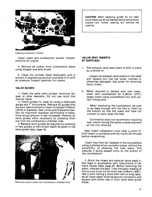
Cleaning Combustion Pocket<br />
Clean insert and combustion pocket. Inspect<br />
carefully for cracks.<br />
4. Remove all carbon from combustion areas<br />
using scraper and wire brush.<br />
5. Clean the cylinder head thoroughly with a<br />
solvent or degreasing solution and blow it off with<br />
air pressure. Inspect carefully for cracks.<br />
VALVE GUIDES<br />
1. Clean the valve stem guides, removing lacquer<br />
or other deposits, Do not use tools that<br />
remove metal.<br />
2. Check guides for wear by using a telescope<br />
gauge and 1" micrometer. Replace all guides that<br />
are worn bell-mouthed or have increased 0.038mm<br />
(.0015) in diameter. See Limits and Clearance Section<br />
for maximum diameter permissible to determine<br />
actual amount it has increased. Remove all<br />
valve guides when necessary by pressing them<br />
out from the combustion chamber side.<br />
3. Replace worn guides as required by pressing<br />
in new guides to the correct depth as given in the<br />
valve guide data, page 42.<br />
VALVE SEAT INSERTS<br />
(IF SUPPLIED)<br />
1. The exhaust valve seat insert is held in place<br />
by a shrink fit.<br />
Inspect all exhaust valve inserts in the head<br />
and replace any that are loose, cracked or<br />
otherwise damaged. Use puller for removing<br />
faulty insert.<br />
When required to replace with new insert,<br />
clean and counterbore for 0.25mm (.010")<br />
larger insert using counterbore tool with correct<br />
fitting pilot.<br />
When machining the counterbore, be sure<br />
to go deep enough with the toot to clean up<br />
the bottom so that the insert will have full<br />
contact to carry away the heat.<br />
Continental does not recommend installing<br />
new inserts having the same outside diameter<br />
as the one removed.<br />
New insert installation must have a press fit.<br />
Chill insert in container with dry ice for 20 minutes<br />
before assembling.<br />
Insert may then be installed in the counterbore<br />
using a piloted driver and arbor press, without the<br />
possibility of shearing the side walls. This<br />
assures it being seated firmly on the bottom of<br />
the counterbore.<br />
Removing Valve Guides from Combustion Chamber Side<br />
3. Grind the intake and exhaust valve seats in<br />
the head in accordance with instructions in the<br />
Valve Guide Data, page 42. Before removing the<br />
arbor, indicate the seat. Total indicator reading of<br />
the run-out must not be more than 0.05mm (.002").<br />
Use a pilot having a solid stem with a long taper,<br />
as all valve seats must be ground concentric and<br />
square with either new or worn valve stem guide<br />
holes.<br />
41