Training Systems for Automation Technology - techno volt
Training Systems for Automation Technology - techno volt
Training Systems for Automation Technology - techno volt
- No tags were found...

You also want an ePaper? Increase the reach of your titles
YUMPU automatically turns print PDFs into web optimized ePapers that Google loves.
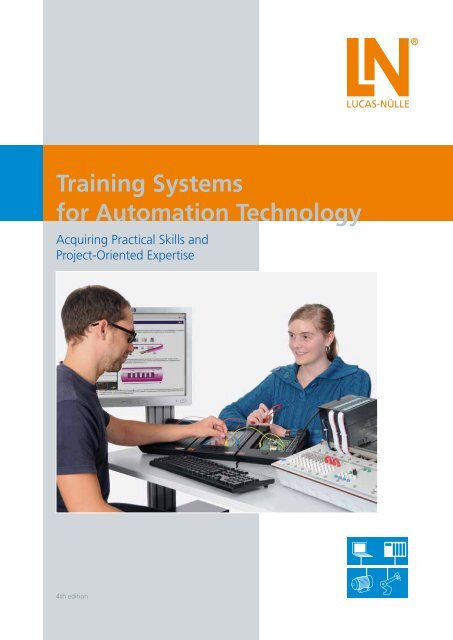
<strong>Training</strong> <strong>Systems</strong><br />
<strong>for</strong> <strong>Automation</strong> <strong>Technology</strong><br />
Acquiring Practical Skills and<br />
Project-Oriented Expertise<br />
4th edition
Table of Contents<br />
Qualifications through Quality<br />
<strong>Training</strong> <strong>Systems</strong> <strong>for</strong> <strong>Automation</strong> <strong>Technology</strong> .......................................................................................................................... 4<br />
Different <strong>Systems</strong> to Fit Differing Needs<br />
Our Objective Is to Meet Everyone’s Standards ........................................................................................................................ 6<br />
Presenting Complex <strong>Training</strong> Content in a Vivid Way<br />
Project-Oriented <strong>Training</strong> Media – Adaptable to All <strong>Training</strong> <strong>Systems</strong> ..................................................................................... 10<br />
The Entire System at a Glance .......................................................................................................................................... 12<br />
More than Just a <strong>Training</strong> System<br />
A Total Solution – the <strong>Automation</strong> Laboratory ....................................................................................................................... 14
Table of Contents<br />
Instrumentation and Automatic Control <strong>Technology</strong>................................................................................................. 16-31<br />
Sensor <strong>Technology</strong> in <strong>Automation</strong><br />
Measurement of Electrical Variables and of Non-Electrical Variables<br />
Automatic Control <strong>Technology</strong><br />
Industrial Installation <strong>Technology</strong> ............................................................................................................................... 32-39<br />
Manually-operated Switching in the Three-phase Circuit<br />
Programmable Compact Controls<br />
Electropneumatics<br />
Programmable Logic Control ....................................................................................................................................... 40-47<br />
Multimedia-Based <strong>Automation</strong>, PLC and Bus <strong>Technology</strong><br />
Programmable Logic Control with SIMATIC S7-300<br />
Networked <strong>Systems</strong> in <strong>Automation</strong> Engineering ....................................................................................................... 48-59<br />
Bus <strong>Systems</strong><br />
Remote Maintenance and Diagnostics<br />
Identification <strong>Systems</strong><br />
Operating and Monitoring<br />
Safety <strong>Technology</strong> in <strong>Automation</strong> <strong>Technology</strong> ........................................................................................................... 60-67<br />
Circuitry Involving Safety Relays<br />
AS-i Safety<br />
PROFIsafe<br />
Optical <strong>Systems</strong><br />
System Models & Process Simulators .......................................................................................................................... 68-77<br />
System Models<br />
Process Simulators<br />
Industrial Mechatronics System IMS ® ........................................................................................................................ 78-101<br />
IMS ® Conveyor Belt <strong>Systems</strong> and Sub-<strong>Systems</strong><br />
IMS ® Robot <strong>Technology</strong><br />
IMS ® Production Lines<br />
IMS ® Virtual<br />
Industrial Process <strong>Automation</strong> IPA .......................................................................................................................... 102-119<br />
IPA Sub-<strong>Systems</strong><br />
IPA Production <strong>Systems</strong><br />
IPA Virtual<br />
Computer Integrated Manufacturing CIM .............................................................................................................. 120-133<br />
Automated Machining <strong>Technology</strong><br />
Lathe Machine<br />
Milling Machine<br />
CIM Production <strong>Systems</strong><br />
Programming Software
Qualifications through Quality<br />
<strong>Training</strong> <strong>Systems</strong> <strong>for</strong> <strong>Automation</strong> Engineering<br />
Technical advances …<br />
<strong>Automation</strong> <strong>techno</strong>logy is becoming ever more important thanks<br />
to the rapid developments taking place in industrial process<br />
auto mation. Developments here are very closely integrated into<br />
other related fields such as drive <strong>techno</strong>logy, automatic control or<br />
computer engineering. Due to the lightning fast pace of development,<br />
automation engineering has become one of the most<br />
innovative and rapidly changing fields in electrical engineering.<br />
… have an enormous impact on vocational<br />
training and education<br />
New industrial solutions necessitate new training systems.<br />
Innovations in decentralisation and visualisation, the introduction<br />
of the internationally applicable IEC1 131-3 standard,<br />
and thus the uni<strong>for</strong>m PLC programming of controls according<br />
to uni<strong>for</strong>m rules and regulations are just a few examples of the<br />
way vocational training is being revolutionised.<br />
The need <strong>for</strong> modern, practice-oriented training systems that<br />
can convey state-of-the-art <strong>techno</strong>logy and the skills needed to<br />
master them arises from the demands being made on today‘s<br />
auto mation technicians.<br />
4<br />
Lucas-Nülle
A strong partnership with industry<br />
That is what provides the guarantee <strong>for</strong> a hands-on, practical<br />
application. Lucas-Nülle has found an excellent partner in market<br />
leader Siemens AG. The most modern products to be found in<br />
automation <strong>techno</strong>logy have been provided by Siemens AG to<br />
be modified <strong>for</strong> teaching purposes and adapted <strong>for</strong> the precise<br />
requirements of training colleges and educational institutions. All<br />
of the curriculum requirements are covered regardless of the level<br />
of difficulty from the compact basic system version all the way<br />
to modular high-end systems with field bus interface and decentralised<br />
peripherals including operating and monitoring equipment.<br />
Safety <strong>techno</strong>logy, too, has of course been integrated into all of<br />
the systems in con<strong>for</strong>mance with the latest European guidelines<br />
pertaining to machinery. The modular and scalable training system<br />
<strong>for</strong>ms the innovative and future-proof foundation <strong>for</strong> excellent and<br />
in-depth training in the area of automation engineering.<br />
Lucas-Nülle<br />
5
Different <strong>Systems</strong> to Fit Differing Needs<br />
Our Objective Is to Meet Everyone’s Standards<br />
UniTrain-I<br />
With the multimedia-based experiment and training system UniTrain-I, students are guided through the individual experiment steps<br />
of a well-structured and educationally designed course assisted by texts, graphics, animations and tests.<br />
In addition to the training software, each course contains an experiment card that allows the practice-oriented assignments to be<br />
per<strong>for</strong>med. Courses on automation engineering convey the knowledge and skills needed to understand the control, operation and<br />
maintenance of modern process automation systems. In these various courses, animations and numerous experiments on authentic<br />
systems assist the students in working their way through the fundamentals, principles and component features of automated processes<br />
and manufacturing systems.<br />
Your benefits<br />
• Theory and practice at the same time and the same place<br />
• High student motivation induced by PC support and new<br />
media<br />
• Rapid learning success thanks to well-structured course<br />
design<br />
• Rapid comprehension of theory thanks to animation and<br />
graphics<br />
• Technical skills trained with autonomous experimenting<br />
• Constant feedback provided by comprehension questions<br />
and tests<br />
• Guided trouble-shooting using integrated fault simulator<br />
• Guaranteed safety thanks to extra-low safety <strong>volt</strong>age<br />
• Huge selection of courses (courses on more than 100 topics<br />
available)<br />
• Sample solutions <strong>for</strong> trainers<br />
6<br />
Lucas-Nülle
UniTrain-I system<br />
• Comprehensive portable<br />
laboratory<br />
• Multimedia courses<br />
• High-tech measurement and<br />
control interface<br />
• Theory and practice<br />
in conjunction<br />
UniTrain-I interface with<br />
USB interface<br />
• Oscilloscope with 2 analogue<br />
differential inputs<br />
• Sampling rate 40 Msamples/s<br />
• 9 measuring ranges<br />
100 mV - 50 V<br />
• 22 time ranges 1 μs - 10 s<br />
• 16 digital inputs/outputs<br />
• Function generator <strong>for</strong> frequencies<br />
up to 1 MHz<br />
• 8 relays <strong>for</strong> fault simulation<br />
UniTrain-I experimenter<br />
• Accommodates experiment<br />
cards<br />
• Experiment <strong>volt</strong>age supply<br />
± 15 V, 400 mA<br />
• Experiment <strong>volt</strong>age supply<br />
5 V, 1 A<br />
• Variable DC or three-phase<br />
source 0 ... 20 V, 1 A<br />
• IrDa interface <strong>for</strong> multimeter<br />
• Additional serial interface <strong>for</strong><br />
cards<br />
Integrated measuring equipment<br />
and power supplies<br />
• Multimeter, ammeters,<br />
<strong>volt</strong>meters<br />
• Dual-channel storage oscilloscope<br />
• Function generator and wave<strong>for</strong>m<br />
generator<br />
• PROFIBUS monitor<br />
• PROFIBUS tester<br />
• ... and many other instruments<br />
LabSoft training and<br />
experiment software<br />
• Huge selection of courses<br />
• Comprehensive theory<br />
• Animations<br />
• Interactive experiments with<br />
instructions<br />
• Free navigation<br />
• Documentation of experiment<br />
results<br />
• Tests<br />
Lucas-Nülle<br />
7
Different <strong>Systems</strong> to Fit Differing Needs<br />
<strong>Training</strong> panel system<br />
Whether it be <strong>for</strong> conventional classroom instruction or practice-oriented student experiments, the training panel system allows<br />
teachers to employ a variety of instructional methods. The training panels consist of moulded panels, both sides of which are melamine<br />
resin painted in a dark anthracite colour. All panels are to uni<strong>for</strong>m DIN A4 dimensions.<br />
Panel system<br />
Your benefits<br />
• Multifaceted and flexible thanks to modular design<br />
• Suitable <strong>for</strong> student exercises and demonstration<br />
• Safe thanks to double insulation (safety sockets and safety cables)<br />
• Integration of industrial components makes systems similar to industrial use<br />
• Clear and legible front panel thanks to contrast-rich and scratch-proof printing process<br />
• Modern instrumentation with PC connection<br />
• Colourful experiment and technical training handbooks<br />
• Student worksheets and sample solutions<br />
8<br />
Lucas-Nülle
Assembly and installation exercise system<br />
When it comes to installation and assembly exercises it is the technical skills and workmanship that count. All of these exercises are<br />
highly hands-on and practice-oriented. The connections are carried out using industrial methods and wiring materials (mounting rails,<br />
terminal strips, screws etc.). All parts except <strong>for</strong> disposable components (such as leads) are reusable.<br />
Assembly and installation exercises<br />
Your benefits<br />
• Plan and implement projects<br />
• Learn connection techniques<br />
• High degree of practical experience using industrial-type technical documentation<br />
and software<br />
• Combinable with the training panel system<br />
• Circuitry is implemented using industrial components<br />
• Complete project documentation<br />
• Perfect compliment <strong>for</strong> project-oriented instruction<br />
Lucas-Nülle<br />
9
Presenting Complex <strong>Training</strong> Content<br />
in a Vivid Way<br />
Project-Oriented <strong>Training</strong> Media – Adaptable to All <strong>Training</strong> <strong>Systems</strong><br />
Manuals<br />
These provide not only the detailed descriptions needed to set<br />
up the respective training systems but also numerous exercises,<br />
examples and projects.<br />
Multimedia courses<br />
Many of the manuals are available in the <strong>for</strong>m of multimedia<br />
courses. They contain features familiar from the UniTrain-I<br />
courses, such as:<br />
• Test questions<br />
• Interactive experiment set-ups<br />
• Navigation bars<br />
• Animated theory<br />
10<br />
Lucas-Nülle
QuickCharts<br />
These provide a quick overview of a certain subject or training<br />
area. Work steps, work processes and technical contexts are<br />
explained clearly and concisely.<br />
Presentation transparencies<br />
These support your lessons with, <strong>for</strong> example, background in<strong>for</strong>mation,<br />
block circuit diagrams, basic physics, specific standard<br />
parameters, special modifications and applications. Supplied as a<br />
CD with a set of transparencies in PowerPoint <strong>for</strong>mat.<br />
Lucas-Nülle<br />
11
The Entire System at a Glance<br />
Safety <strong>techno</strong>logy<br />
in automation engineering CSY 1<br />
Circuits<br />
with control relay<br />
CSY 2<br />
AS-Interface<br />
with safety motor<br />
CSY 3<br />
Fail-safe PLC<br />
PROFIsafe<br />
Networking, operating and monitoring<br />
of automation systems<br />
CAS 1<br />
AS-Interface<br />
CDP 1<br />
PROFIBUS DP<br />
CIM<br />
Computer Integrated Manufacturing<br />
ILA Interactive Lab Assistant course<br />
Machining <strong>techno</strong>logy with CIM installations<br />
IPA<br />
Industrial process engineering<br />
systems<br />
UniTrain-I multimedia course<br />
Process engineering with IPA sub-systems<br />
IMS ®<br />
Industrial Mechatronics System<br />
UniTrain-I multimedia course<br />
Mechatronics with IMS ® conveyor belt and sub-systems<br />
Process simulators<br />
Process system models<br />
Plant models<br />
CLC 33<br />
PLC circuit board models<br />
CLC 34<br />
PLC universal plant simulator<br />
Programmable logic controls<br />
UniTrain-I multimedia course<br />
<strong>Automation</strong> engineering (PLC + bus <strong>techno</strong>logy)<br />
Industrial installation <strong>techno</strong>logy<br />
UniTrain-I multimedia course<br />
<strong>Automation</strong> engineering (Electropneumatics)<br />
Instrumentation and<br />
Automatic Control <strong>Technology</strong><br />
UniTrain-I multimedia course<br />
Sensors, instrumentation, automatic control <strong>techno</strong>logy<br />
12<br />
Lucas-Nülle
CSY 4/5<br />
Application of<br />
optical systems<br />
CPN 1/2<br />
Industrial Ethernet/<br />
PROFINET<br />
CFW 1<br />
Remote maintenance<br />
CCS 2<br />
Operation and<br />
monitoring<br />
CVS1<br />
Image processing<br />
CLP 20<br />
Open-loop control<br />
of electrical drives<br />
CID1<br />
RFID<br />
CIM 1-2<br />
CIM installations<br />
CIM 1n & 2n<br />
Flexible machine processing<br />
system<br />
IPA 1-5<br />
IPA sub-systems<br />
IPA 2n<br />
Flexible process engineering<br />
system<br />
IMS ® 1-11<br />
IMS ®<br />
Conveyor belt and sub-systems<br />
IMS ® 2n<br />
Flexible mechatronics<br />
system (FMS)<br />
CLC 35<br />
Process simulation<br />
ProTrain <strong>for</strong> Windows<br />
CLC 40<br />
Electrical PLC process models<br />
CLC 36<br />
Automatic control <strong>techno</strong>logy<br />
in automation engineering<br />
CLC 30<br />
SIMATIC S7-300<br />
pre-configured basic set<br />
CLC 30<br />
SIMATIC S7-300<br />
modular assembly<br />
EST 1<br />
Manual switching<br />
EST 2<br />
Contactor circuits<br />
EST 4<br />
Programmable compact control LOGO!<br />
IAC<br />
Applied control <strong>techno</strong>logy –<br />
automatic flow-rate and liquid-level control<br />
EPE<br />
Applied automatic control <strong>techno</strong>logy –<br />
closed-loop drive control<br />
Lucas-Nülle<br />
13
More than Just a <strong>Training</strong> System<br />
A Total Solution – the <strong>Automation</strong> Laboratory<br />
Presenting complex training content in a vivid way<br />
using modern training media<br />
Flexible process engineering<br />
production systems with IPA<br />
Simple introduction<br />
to each IMS ® sub-system<br />
using multimedia<br />
UniTrain-I courses<br />
CNC programming directly on the lathe<br />
and milling machine or in 3D simulation<br />
Flexible production systems with IMS ®<br />
14<br />
Lucas-Nülle
Each IPA station can be operated using an industrial PLC<br />
unit or with the UniTrain-I process and automatic control<br />
Complete solutions <strong>for</strong> process control systems:<br />
PLC, AS-i, PROFIBUS, PROFINET, HMI, remote maintenance,<br />
safety <strong>techno</strong>logy, drive <strong>techno</strong>logy<br />
The system models and process simulators<br />
offer a multitude of control assignments<br />
With UniTrain-I, multimedia is used<br />
to develop know-how and skills<br />
Lucas-Nülle<br />
15
Instrumentation and<br />
Automatic Control <strong>Technology</strong><br />
Sensor <strong>Technology</strong> in <strong>Automation</strong> ........................................... 20<br />
Measurement of Electrical Variables ........................................ 21<br />
Measurement of Non-electrical Variables ................................. 22<br />
RLC Measurement .................................................................. 24<br />
Practical Introduction to Closed-loop Control <strong>Technology</strong> ........ 25<br />
Analysis of Control Loops ........................................................ 26<br />
Control Loop Design and Optimization ................................... 27<br />
Applied Automatic Control <strong>Technology</strong> ................................... 28<br />
Closed-loop Control in <strong>Automation</strong> Engineering ..................... 31
Instrumentation and Automatic Control <strong>Technology</strong><br />
Instrumentation and<br />
Automatic Control <strong>Technology</strong><br />
Instrumentation<br />
The measurement of analog, non-electrical variables is of critical importance and is basic to all areas of automation engineering.<br />
After all, it is the detection of the physical variable and its conversion into electrical signals which makes the automatic control of a<br />
system possible in the first place.<br />
Automatic Control <strong>Technology</strong><br />
Using the automatic control <strong>techno</strong>logy training system, the student is not only introduced to the basics but also gains insight into<br />
more advanced areas in a graphic and practice-oriented way. In the process, modern training systems, such as digitally operating<br />
con trollers and multimedia-based training systems, are used to convey practical skills and competence to the trainees.<br />
18<br />
Lucas-Nülle
Instrumentation and Automatic Control <strong>Technology</strong><br />
Sensor <strong>techno</strong>logy<br />
<strong>Automation</strong> and closed-loop control <strong>techno</strong>logy is based on the<br />
detection of the physical operating states of a process and the<br />
variables which have an effect on it. This is per<strong>for</strong>med by a wide<br />
range of sensors that operate according to different physical<br />
principles. For that reason, knowledge of sensor <strong>techno</strong>logy is<br />
indispensable <strong>for</strong> anyone who has anything to do with automation<br />
or automatic control <strong>techno</strong>logy, and that means the<br />
mechatronics specialists, too.<br />
Closed-loop control <strong>techno</strong>logy in automation<br />
Closed-loop control <strong>techno</strong>logy is of paramount significance <strong>for</strong><br />
modern technical systems. Optimised control loops assist in production<br />
and process engineering, in order to efficiently exploit<br />
resources such as energy and raw materials and to ensure pro duct<br />
quality. Furthermore, by integrating closed-loop control <strong>techno</strong>logy<br />
it is possible to develop innovative and intelligent products,<br />
a pre requisite to global competitiveness.<br />
Source: Thyssen Krupp<br />
<strong>Training</strong> systems<br />
Our training systems cover the following subjects:<br />
• Sensor <strong>techno</strong>logy<br />
• Instrumentation<br />
• Automatic control <strong>techno</strong>logy<br />
Lucas-Nülle<br />
19
Instrumentation and Automatic Control <strong>Technology</strong><br />
Sensor <strong>Technology</strong> in <strong>Automation</strong><br />
Industrial Sensors<br />
Sensors are needed <strong>for</strong> the open-loop control of technical processes using programmable controllers. They convert physical variables<br />
into electrical output signals and assume the function of the human senses. As such, sensor <strong>techno</strong>logy is fundamental to this field<br />
and indispensable <strong>for</strong> any automation technician.<br />
UniTrain-I course ”Sensor <strong>techno</strong>logy in automation“<br />
<strong>Training</strong> contents<br />
• Working with capacitive and inductive proximity switches<br />
• Working with various types of sensors such as magnetic field or optical sensors<br />
• Exploring which sensor responds to which material<br />
• Determining the switching gap, hysteresis and operating frequency<br />
• Methods of testing various materials using sensors driven electrically along the X-axis<br />
20<br />
UniTrain-I sensor <strong>techno</strong>logy in automation equipment set<br />
Lucas-Nülle
Instrumentation and Automatic Control <strong>Technology</strong><br />
Measurement of Electrical Variables<br />
Current/Voltage – Power – Work – Frequency<br />
The introduction to electrical measurement techniques is based on moving-iron and moving-coil galvanometers. Here the instruments<br />
are used to measure <strong>volt</strong>ages and currents, to work out the effect of the characteristic response on the measurement result,<br />
and to expand the measurement range using additional resistors.<br />
UniTrain-I course ”Measurement of electrical variables“<br />
<strong>Training</strong> contents<br />
• Power measurement<br />
• Elaboration of measurement principles using DC circuits<br />
• Working through the differences between active, apparent and reactive power measurement<br />
in simple experiments on an AC circuit<br />
• Measurement and explanation of power factor<br />
• Load measurements and measurement of electrical work with the aid of a Ferraris meter<br />
UniTrain-I measurement of electrical variables equipment set<br />
Lucas-Nülle<br />
21
Instrumentation and Automatic Control <strong>Technology</strong><br />
Measurement of Non-Electrical Variables<br />
Temperature – Pressure – Force – Torque<br />
In modern day industrial practice it is becoming more and more a necessary to monitor, display or electronically process physical<br />
variables. To do this, you have to use the appropriate tools to convert non-electrical variables into electrical ones.<br />
UniTrain-I course ”Measurement of non-electrical variables TPF“<br />
<strong>Training</strong> contents<br />
• Elaboration of the influence of measurement circuits<br />
• Characteristics of different temperature sensors: NTC, Pt 100, KTY, thermocouples<br />
• Pressure measurement: piezo-electric, inductive and resistive pressure sensors<br />
• Principle of <strong>for</strong>ce measurement with strain gauges applied to bending bars and torsion rods<br />
• Recording characteristics <strong>for</strong> different sensors<br />
• Methods <strong>for</strong> linearising non-linear characteristics<br />
• Identifying possible fault sources<br />
22<br />
UniTrain-I measurement of non-electrical variables TPF equipment set<br />
Lucas-Nülle
Instrumentation and Automatic Control <strong>Technology</strong><br />
Measurement of Non-Electrical Variables<br />
Displacement – Angle – Speed<br />
In mechatronics or drive-<strong>techno</strong>logy applications found in manufacturing, the rapid and precise detection of such variables as<br />
displacement, angle and speed are critical <strong>for</strong> the system‘s dynamic response, efficiency and quality.<br />
UniTrain-I course ”Measurement of non-electrical variables sαn“<br />
<strong>Training</strong> contents<br />
• Analog and digital methods used <strong>for</strong> displacement, angle and speed measurement<br />
• Introduction to the required sensors, their operation and characteristics<br />
• Experiment-based determination of characteristics<br />
• Calibration and measurement circuitry<br />
• Experiments with capacitive and inductive-type sensors<br />
• Use of optical sensors and Hall sensors <strong>for</strong> detecting the position of rotating shafts<br />
• Per<strong>for</strong>ming incremental, BCD and Gray code encoder displacement measurement<br />
• Per<strong>for</strong>ming investigations on rotating shafts using a resolver<br />
UniTrain-I measurement of non-electrical variables sαn equipment set<br />
Lucas-Nülle<br />
23
Instrumentation and Automatic Control <strong>Technology</strong><br />
RLC Measurement<br />
Resistance – Inductance – Capacitance<br />
Bridge and impedance measurement methods have been used <strong>for</strong> years in bridge measurement circuits to determine the parameters<br />
of passive components such as resistors, capacitors and inductors.<br />
UniTrain-I course ”RLC measurement“<br />
<strong>Training</strong> contents<br />
• RLC measurement is per<strong>for</strong>med using calibrated examples of the following:<br />
- Wheatstone bridge<br />
- Maxwell-Wien bridge<br />
- Wien bridge<br />
• Elaboration of measurement principles<br />
• Measurement with an RLC meter<br />
• Comparison of measurement results<br />
24<br />
UniTrain-I equipment set <strong>for</strong> RLC measurement<br />
Lucas-Nülle
Practical Introduction<br />
to Automatic Control <strong>Technology</strong><br />
Instrumentation and Automatic Control <strong>Technology</strong><br />
Closed-Loop Temperature – Speed – Light – Flow-Rate Control<br />
In the age of automation, automatic control <strong>techno</strong>logy is of paramount importance in modern technical systems.<br />
UniTrain-I course ”Practical introduction to automatic control <strong>techno</strong>logy“<br />
<strong>Training</strong> contents<br />
• Operating principles of open-loop and closed-loop control<br />
• Design and operation of continuous and discontinuous controllers<br />
• Hands-on investigation of control loops with continuous controllers<br />
• Automatic temperature control of a sauna with 2-position controller<br />
• Design and optimisation of an automatic speed control with continuous controllers<br />
• Control response to set-point changes and disturbance response of a light control loop<br />
• Automatic flow-rate control with 2-position controller and PI controller<br />
(requires optional ”liquid-level“ controlled system model)<br />
UniTrain-I practical introduction to automatic control <strong>techno</strong>logy equipment set<br />
Lucas-Nülle<br />
25
Instrumentation and Automatic Control <strong>Technology</strong><br />
Analysis of Control Loops<br />
Control Loop Elements – Continuous Controllers – Discontinuous Controllers<br />
– Closed Control Loops<br />
A basic understanding <strong>for</strong> the operational response of different controller types and controlled systems in the time and frequency<br />
domains is decisive <strong>for</strong> selecting the right controller and getting reliable control loop operation.<br />
UniTrain-I Kurs ”Analyse von Regelkreise<br />
UniTrain-I course ”Analysis of control loops“<br />
<strong>Training</strong> contents<br />
• Recording the step responses to determine the response<br />
and characteristic values of various control loop elements<br />
such as:<br />
- P-action elements<br />
- I-action elements<br />
- Two PT1 elements<br />
- Non-linear elements<br />
- Arithmetic elements<br />
• Exploring appropriate controller types<br />
• Optimising closed control loops<br />
• Analysis of control loops and controlled systems using<br />
Bode diagrams<br />
• Static and dynamic responses of control loop elements<br />
and closed control loops<br />
26<br />
UniTrain-I analysis of control loops equipment set<br />
Lucas-Nülle
Instrumentation and Automatic Control <strong>Technology</strong><br />
Design and Optimisation of Controllers<br />
Real Controlled <strong>Systems</strong> – Optimisation Guidelines – Controller Optimisation<br />
– Stability Analysis – Numerical and Fuzzy Control<br />
These equipment sets supplementary to the ”Analysis of control loops“ course using real controlled systems provide graphic and<br />
more advanced, in-depth understanding of automatic control <strong>techno</strong>logy.<br />
Fuzzy control is needed to regulate complex measurement variables and non-linear systems. Such fuzzy systems can be integrated<br />
into the automatic control components of the UniTrain-I system by adding a supplementary software package.<br />
UniTrain-I Kurs ”Reglerentwurf und Optimierung“<br />
UniTrain-I course “Design and Optimisation of Controllers“<br />
<strong>Training</strong> contents<br />
• Determine the parameters of real controlled systems:<br />
- Temperature-controlled systems<br />
- Speed-controlled systems<br />
- Light-controlled systems<br />
• Observe system response with continuous and<br />
discontinuous controllers in a closed control loop<br />
• Investigate the control response to set-point change<br />
and disturbance variables<br />
• Per<strong>for</strong>m design and optimisation in the time and<br />
frequency domains<br />
• Assessment of control quality and stability analysis in the<br />
frequency domain by plotting a Bode diagram, i.e. locus<br />
curve<br />
• Numerical and fuzzy control:<br />
- Simulation of control loops on a PC<br />
- Real-time control using a PC<br />
- Investigation of a fuzzy controller<br />
- Automatic fuzzy control of real controlled systems<br />
UniTrain-I design and optimisation of controllers equipment set<br />
Lucas-Nülle<br />
27
Instrumentation and Automatic Control <strong>Technology</strong><br />
Applied Automatic Control <strong>Technology</strong><br />
Servo <strong>techno</strong>logy<br />
The DC servo training system demonstrates the precise automatic control of both the angle as well as the speed. Using incremental<br />
encoders the DC servo drive’s position and speed are detected with precision and transmitted to the PC in the <strong>for</strong>m of a data set <strong>for</strong><br />
further processing. This includes the recording of step responses and the determining of the time constants. The requisite know-how<br />
is acquired in hands-on exercises which include correct parameterisation and deployment of the P-, I-, PID and cascade controllers<br />
and ultimately in understanding how these affect the overall system. Project work entails the realisation of a time-dependent positioning<br />
control sequence involving a rotating disc.<br />
<strong>Training</strong> contents<br />
• Analysis of a DC motor operating in the context of an open- and closed-loop control system<br />
• Automatic angle and speed control<br />
• Detection of the DC servo’s speed and position using an incremental encoder<br />
• Determination of the control characteristic, dead time, transient response, control deviation and oscillation<br />
• Recording the step response<br />
• Determining the time constants<br />
• Putting different controller types into operation<br />
• Investigating how the servo drive responds to load variations<br />
28<br />
UniTrain-I servo <strong>techno</strong>logy equipment set<br />
Lucas-Nülle
Instrumentation and Automatic Control <strong>Technology</strong><br />
Static Converters with DC Motors<br />
The static converter equipment sets can be expanded into converter drives at minimum added cost simply by adding the corresponding<br />
electrical machine. The digital controller then trans<strong>for</strong>ms this assembly into an automatically controlled drive. To investigate the<br />
drive under load in four-quadrant operation mode all you need is a servo brake.<br />
Experiment example ”Closed-loop speed control of a DC motor EPE 11“<br />
<strong>Training</strong> contents<br />
• Closed-loop speed control in single- to four-quadrant operation with and without secondary current control loop<br />
• Speed control with single and double converters or IGBTs<br />
• Four-quadrant mode, power recovery<br />
• Automatic speed control, current control, cascade control, adaptive control<br />
• Computer-assisted system and controller analysis, parameter setting<br />
• P, PI, PID control<br />
• Optimisation of controller<br />
• Response of automatically controlled DC motors with line-commutated static converters (EPE 11) /<br />
self-commutated converters (EPE 21)<br />
EPE 11 and 21 equipment sets<br />
Lucas-Nülle<br />
29
Instrumentation and Automatic Control <strong>Technology</strong><br />
Applied Automatic Control <strong>Technology</strong><br />
Closed-Loop Liquid-Level Control – Flow-Rate Control<br />
The ”Automatic liquid-level control“ system is an applied control <strong>techno</strong>logy experiment designed specifically <strong>for</strong> training and reallife<br />
applications. The compact training unit contains a liquid reservoir, a pressure transducer to detect the actual liquid level as well as<br />
a reserve tank including pump. To achieve constant pumping power, a secondary control loop with a flow-rate meter is integrated,<br />
although it can also be disconnected. Disturbance variables can be simulated using adjustable throttle valves, which modify the inlet<br />
and outlet flows at the liquid reservoir. As an option, a second liquid reservoir can be included to assemble a controlled system with<br />
time delays of the second-order time delays.<br />
Experiment example ”Automatic liquid-level control IAC 10/11“<br />
<strong>Training</strong> contents<br />
• Parameters of controlled system<br />
• Design and function of closed control loop<br />
• Two-position controller in an integral-action controlled system<br />
• Two-position controller in a controlled system with higher order time delay<br />
• Automatic liquid level-control with continuously operating PI/PID controller<br />
• Automatic liquid level-control with secondary flow-rate control loop<br />
• Automatic liquid level-control in a system with higher order time delay<br />
• Disturbance response of control loop<br />
30<br />
IAC 10/11 equipment set<br />
Lucas-Nülle
Automatic Control <strong>Technology</strong><br />
in <strong>Automation</strong> Engineering<br />
Instrumentation and Automatic Control <strong>Technology</strong><br />
One Model – Two Functions: Automatic Liquid-Level and Flow-Rate Control<br />
Due to the fact that the controlled variable, that is to say the level of liquid, is immediately visible, this experiment is a particularly<br />
graphic one and thus eminently suitable <strong>for</strong> an introduction to automatic control <strong>techno</strong>logy. The compact training unit contains a<br />
liquid reservoir and a pressure transducer to determine the actual liquid level, as well as reserve tanks including a pump. Disturbance<br />
variables can be simulated using adjustable throttle valves which modify the inlet and outlet flows at the reservoir.<br />
Experiment example ”Liquid-level controlled system CLC 36“<br />
<strong>Training</strong> contents<br />
Automatic liquid-level control<br />
• Assembly, calibration and optimisation<br />
of a liquid-level control loop with<br />
variable system characteristics<br />
• Two-position controller in an integralaction<br />
system and a controlled<br />
system with higher order delay<br />
• Two-position controller with delayed<br />
feedback in a liquid-level control loop<br />
• Two-position controller with float<br />
switch<br />
• Automatic liquid-level control with<br />
disturbance variable <strong>for</strong>ward feed<br />
and pre-control<br />
• Second-order time delay controlled<br />
system with optional supplementary<br />
tank<br />
Automatic flow-rate control<br />
• Assembly, calibration and optimisation<br />
of a flow-rate control loop<br />
connected to a liquid level controlled<br />
system<br />
• Principle, response and deployment<br />
of flow-rate measurement<br />
• Investigation of closed-loop flow-rate<br />
control response to disturbance variables<br />
and set-point step changes<br />
CLC 36 equipment set<br />
Lucas-Nülle<br />
31
Industrial Installation<br />
<strong>Technology</strong><br />
Manually-operated Switching in the Three-phase Circuit ......... 36<br />
Contactor Circuitry in Three-phase Circuits .............................. 37<br />
Programmable Micro-controls ................................................. 38<br />
Pneumatics in Automated Control .......................................... 39
Industrial Installation <strong>Technology</strong><br />
Industrial Installation <strong>Technology</strong><br />
The Challenge: Rapid Data Monitoring <strong>for</strong> Processes<br />
Modern industrial installation is making very high demands on the abilities of electricians. Reading complex circuit diagrams,<br />
selecting the appropriate equipment, calculating figures <strong>for</strong> the necessary safety mechanisms and the programming of control<br />
units are just some of their everyday activities.<br />
34<br />
Lucas-Nülle
Industrial Installation <strong>Technology</strong><br />
Electropneumatics<br />
Use of compressed air to transmit power has become more and<br />
more attractive as time goes on. The advantage of pneumatics<br />
is that actuators are simple and cost-effective to design and<br />
implement, <strong>for</strong> example, in the <strong>for</strong>m of pneumatic cylinders. In<br />
contrast to purely pneumatic controls, electropneumatic units<br />
permit the implementation of considerably more complex functions,<br />
particularly through the use of electronic circuits such as<br />
programmable logic controls, <strong>for</strong> example.<br />
Installation <strong>techno</strong>logy<br />
The new compact boards constitute a cost-effective complement<br />
to the comprehensive, modular experiment systems used in process<br />
control <strong>techno</strong>logy.<br />
By including additional function elements and allowing various<br />
teams to work in conjunction, it is possible to achieve excellent<br />
results in comprehensive projects over a longer period of time.<br />
<strong>Training</strong> systems<br />
In order to fulfil all of these demands, the training systems cover<br />
the following topics:<br />
• Direct switching in three-phase circuits<br />
• Contactor circuits in three-phase circuits<br />
• Complex process system circuitry<br />
• Programmable mini controls<br />
• Electropneumatics in automation <strong>techno</strong>logy<br />
Lucas-Nülle<br />
35
Industrial Installation <strong>Technology</strong><br />
Manually Operated Switches<br />
in a Three-phase Circuit<br />
Practice-Oriented <strong>Training</strong> in Process Control <strong>Technology</strong><br />
The development of circuits and the appropriate choice of circuit elements and equipment lie at the focal point of this training<br />
segment. Multi-pole loads can be connected directly into a three-phase circuit up to a specified power class. To accomplish this there<br />
are corresponding switching devices, which may be deployed differently depending on the application.<br />
Experiment example ”Manually operated switches in a three-phase circuit EST 1“<br />
<strong>Training</strong> contents<br />
• Manual switching in a three-phase circuit<br />
• Contactor circuits in a three-phase circuit<br />
• Programmable mini controls<br />
• Switch-off <strong>for</strong> a three-phase induction motor with<br />
squirrel-cage rotor<br />
• Star-delta circuit <strong>for</strong> a three-phase induction motor with<br />
squirrel-cage rotor<br />
• Star-delta reversing circuit <strong>for</strong> a three-phase induction<br />
motor with squirrel-cage rotor<br />
• Three-phase induction motor with Dahlander polechanging<br />
circuit<br />
• Three-phase induction motor with two separate windings<br />
and pole-changing circuit<br />
36 EST 1 equipment set<br />
Lucas-Nülle
Industrial Installation <strong>Technology</strong><br />
Contactor Circuits in a Three-phase Circuit<br />
Switching Large Loads On and Off<br />
Above a certain power class it is no longer possible to switch three-phase loads directly on line. For that reason, loads are indirectly<br />
activated using contactor circuits of the most varied of types. The development of the control circuit and the design with function<br />
control <strong>for</strong>m the focal point of this training unit. Together with the supplementary equipment sets, additional more extensive control<br />
operations can be handled. The supplementary machine set contains the machines and equipment units needed to test the circuits<br />
<strong>for</strong> direct and indirect control of motors connected into the three-phase circuit.<br />
Experiment example ”Contactor circuits in a three-phase circuit EST 2“<br />
<strong>Training</strong> contents<br />
• Drawing a circuit diagram<br />
• Setting a motor protection relay according to the<br />
motor‘s rating plate<br />
• Contactor circuitry with self-latching<br />
• Switch-on delay relays and drop-out delay relays<br />
• Pulse contactor circuit<br />
• Reverse contactor control with interlocking<br />
• Limiting control with mechanical limit switches<br />
and rotation reversal<br />
• Star-delta circuits<br />
• Function testing and fault finding<br />
• Three-phase motor connection<br />
• Protective, safety and switch-off functions<br />
• Project planning, construction and commissioning of<br />
complex controls<br />
EST 2 equipment set<br />
Lucas-Nülle<br />
37
Industrial Installation <strong>Technology</strong><br />
Programmable Compact Controls<br />
Ideal Introduction to Process Control Assignments<br />
The initial foundation stones <strong>for</strong> the programming of compact control systems were built on classic process control and digital <strong>techno</strong>logy.<br />
These exercises serve as preparation <strong>for</strong> training in automation <strong>techno</strong>logy. The compact controllers are equipped with their<br />
own displays. Programming can be carried out without the need <strong>for</strong> an additional PC.<br />
LOGO! process control of a lift<br />
Experiment example ”Programmable LOGO! compact controller EST 4“<br />
LOGO! process control of a conveyor belt<br />
<strong>Training</strong> contents<br />
• Programming logic functions<br />
• Programming timing elements<br />
• Complex control tasks<br />
• PC programming, visualisation and documentation of an application<br />
38 EST 4 equipment set<br />
Lucas-Nülle
Industrial Installation <strong>Technology</strong><br />
Pneumatics in <strong>Automation</strong><br />
Pneumatic Cylinders – Directional Control Valves – Process Control Elements<br />
Use of compressed air to transmit power has become more and more attractive. Pneumatic systems are frequently being used <strong>for</strong> such<br />
tasks as transport, drilling, grinding, winding, sorting, and open- and closed-loop controls. This can be attributed to the fact that in some<br />
automation tasks there is simply no better or more efficient tool that can be used.<br />
UniTrain-I course ”Electropneumatcs“<br />
<strong>Training</strong> contents<br />
• Basics of pneumatics<br />
• How single- and double-acting cylinders work<br />
• Familiarisation with various directional control valves<br />
• Operation and design of electropneumatic controls<br />
• Hard-wired controls<br />
• Programmable controls<br />
• Recording displacement/time graphs<br />
• Time-dependent controls<br />
UniTrain-I Pneumatics equipment set<br />
Lucas-Nülle<br />
39
Programmable Logic Control<br />
Multimedia-based <strong>Automation</strong>, PLC and Bus <strong>Technology</strong> ........ 44<br />
Programmable Logic Controls with SIMATIC S7-300 ................ 46
Programmable Logic Control<br />
Programmable Logic Control<br />
An Integral Component of <strong>Automation</strong> Engineering<br />
New focal points in training and education reflect new skills and qualifications<br />
in the disciplines of process control <strong>techno</strong>logy, electro-mechanics,<br />
electronics and computer-assisted control systems (PLC). The basics of PLC<br />
<strong>techno</strong>logy as well as how it works are graphically demonstrated using<br />
examples, explanatory texts and practical exercises.<br />
42<br />
Lucas-Nülle
Programmable Logic Control<br />
Multidisciplinary applications<br />
Nowadays, programmable logic control systems are an integral<br />
part of automation engineering. They are used, <strong>for</strong> example, to<br />
control automated processes in the machine industry, <strong>for</strong> transport<br />
and conveyor belts, process engineering, drive systems and<br />
in manufacturing plants.<br />
Time to provide individual support<br />
Basic topics are taught using the UniTrain-I ”<strong>Automation</strong> Engineering“<br />
program. The self-study aspect of the courses means<br />
instructors have more time to provide personal attention to individual<br />
students or small groups. With the UniTrain-I PLC control<br />
system, students get hands-on training using realistic control tasks<br />
and assignments in line with industry standards.<br />
<strong>Training</strong> systems<br />
The training systems focus on conveying basic knowledge<br />
and in<strong>for</strong>mation on programmable logic control (PLC) and<br />
demonstrate how such systems are networked with sensors and<br />
actuators. The fundamentals and operation of PLC systems are<br />
graphically explored using a multitude of examples, explanations,<br />
exercises and practical assignments:<br />
• UniTrain-I PLC and bus <strong>techno</strong>logy<br />
• Programmable logic controls with SIMATIC S7-300<br />
Lucas-Nülle<br />
43
Programmable Logic Control<br />
Multimedia-Based <strong>Automation</strong>,<br />
PLC and Bus <strong>Technology</strong><br />
Programmable Logic Control (PLC)<br />
Today‘s highly automated industrial landscape is characterised by machines which operate more or less automatically. As a rule these<br />
systems are operated by programmable logic control. Developments are leading to more decentralised control systems utilising field bus<br />
systems.<br />
<strong>Training</strong> contents<br />
• Introduction to the fundamentals and basic concepts of PLC systems and how they operate<br />
• Introduction to PLC programming<br />
• Implementing logical operations from storage elements all the way to more complex networks<br />
• Programming of times, counters and self-written functions<br />
• Designing a traffic light circuit<br />
• Conversion of non-electrical measurement variables to electrical signals<br />
• Programming with Instruction List (IL) and Structured Text languages using an editor in compliance with IEC 1131-1<br />
• Programming in Function Block Diagram (FBD), Ladder Diagram (LD) and IL languages with STEP 7<br />
44<br />
UniTrain-I PLC and bus <strong>techno</strong>logy equipment set<br />
Lucas-Nülle
Programmable Logic Control<br />
Field Bus <strong>Systems</strong> – PROFIBUS<br />
A PLC controller alone is no longer seen as the central unit of<br />
an automated system. Complete automation solutions now<br />
integrate sensors, drives and other actuators as well as the<br />
components used <strong>for</strong> system operating and monitoring. Using<br />
standardised field bus systems, it is possible to fully integrate a<br />
variety of different systems, <strong>for</strong> example.<br />
UniTrain-I ”PLC and bus <strong>techno</strong>logy“<br />
<strong>Training</strong> contents<br />
• Operating decentralised peripherals using a network with PROFIBUS DP master and slaves<br />
• Programming and configuration of a field bus using special software tools, such as PROFIBUS Monitor and<br />
PROFIBUS Tester<br />
• Data transmission structures and protocols<br />
• Transmission and fault analysis<br />
Lucas-Nülle<br />
45
Programmable Logic Control<br />
Programmable Logic Control<br />
with SIMATIC S7-300<br />
Fully Configured Basic Equipment Sets<br />
In addition to the recommended basic set, all of the CPUs in the 300 series are available as fully configured units.<br />
To implement automation assignments comparable to those actually used in industry, the STEP 7 software package is employed. The<br />
system features object-oriented programming of automation units in line with the IEC 1131-1 standard. Editors are also available<br />
<strong>for</strong> the languages LD (Ladder Diagram), FBD (Function Block Diagram), IL (Instruction List), ST (Structured Text, designated Structured<br />
Control Language, SCL, in STEP 7) in addition to the GRAPH tool (<strong>for</strong> Sequential Function Chart programming) plus tools <strong>for</strong> software<br />
testing and hardware configuration.<br />
Experiment example ”SIMATIC S7-300 CLC 30“<br />
<strong>Training</strong> contents<br />
• Design and project configuration <strong>for</strong> a PLC<br />
• Creating assignment lists<br />
• Programming in accordance with IEC 1131-1 (IL, LD, FBD, ST/SCL, GRAPH) using STEP 7<br />
• Programming of binary and word operations<br />
• Programming of counters and timers, comparison and arithmetic functions<br />
• Program structure, calling subroutines<br />
• Commissioning, testing and fault finding on an automation system<br />
• Diagnostic functions<br />
• Documentation and archiving<br />
46<br />
CLC 30 equipment set<br />
Lucas-Nülle
Programmable Logic Control<br />
Custom Control SIMATIC S7-300<br />
The training system is an industrial unit with state-of-the-art PLC control and is modularly designed <strong>for</strong> training purposes. The training<br />
system can be configured and expanded in accordance with individual preferences. Thanks to the integrated system bus input<br />
and output modules with safety sockets, it can easily be connected up and input simulations added. The training system can be<br />
expanded from the basic version all the way to a high-end system using a PROFIBUS DP interface and decentralised peripherals.<br />
Experiment example ”SIMATIC S7-300 CLC 31“<br />
<strong>Training</strong> contents<br />
• Design and project configuration <strong>for</strong> a PLC<br />
• Creating assignment lists<br />
• Programming in accordance with IEC 1131-1 (IL, LD, FBD, ST/SCL, GRAPH) using STEP 7<br />
• Programming of binary and word operations<br />
• Programming of counters and timers, comparison and arithmetic functions<br />
• Program structure, calling subroutines<br />
• Commissioning, testing and fault finding on an automation system<br />
• Diagnostic functions<br />
• Documentation and archiving<br />
CLC 31 equipment set<br />
Lucas-Nülle<br />
47
Networked <strong>Systems</strong> in<br />
<strong>Automation</strong> Engineering<br />
AS-interface ............................................................................ 52<br />
PROFIBUS-DP .......................................................................... 53<br />
Industrial Ethernet/PROFINET ................................................... 54<br />
Remote Maintenance and Diagnostics ..................................... 55<br />
RFID ........................................................................................ 56<br />
Image Processing .................................................................... 57<br />
Operation and Monitoring ...................................................... 58<br />
Open-loop Control of Electrical Drive <strong>Systems</strong> ......................... 59
Networked <strong>Systems</strong> in <strong>Automation</strong> Engineering<br />
Complete Solutions <strong>for</strong> <strong>Automation</strong> <strong>Systems</strong><br />
Open-Loop Control with AS-Interface, PROFIBUS and PROFINET<br />
Present day trends in automation engineering are heading towards modular systems with distributed systems. PROFINET, PROFIBUS<br />
and AS-Interface offer all of the networking possibilities <strong>for</strong> various intelligent components – from the lowest field level up to and<br />
including process control and instrumentation. Any components needed to operate and monitor machines (HMI) are integrated into<br />
this bus environment and permit a high degree of process transparency.<br />
50<br />
Lucas-Nülle
Networked <strong>Systems</strong> in <strong>Automation</strong> Engineering<br />
Wiring and maintenance<br />
In order to dramatically reduce wiring and maintenance work on<br />
production lines, standardised field bus systems are increasingly<br />
being used to couple components together. This enables decentralised<br />
organisation of automation equipment, i.e. in close<br />
proximity to the actual sensors and actuators in the field. This<br />
eliminates the need <strong>for</strong> complex and error-prone parallel wiring<br />
of such actuators and sensors.<br />
Field bus level<br />
Thanks to standardised and open field bus protocols, systems<br />
stemming from different manufacturers are able to communicate.<br />
All automation components, including PLC systems, PCs,<br />
operating and monitoring equipment, as well as sensors and<br />
actuators themselves can all exchange data via the field bus. In<br />
order to meet demands <strong>for</strong> real-time process automation, field<br />
bus systems operate with very high data rates.<br />
UniTrain-I<br />
<strong>Training</strong> systems<br />
The training systems cover all areas of control systems from<br />
simple bus structures to complex networks. One key benefit is<br />
common to all the systems and that is their rapid set-up times.<br />
By using typical industrial components, bus structures can be<br />
modified and expanded with a high degree of flexibility.<br />
Human Machine Interface (HMI) <strong>techno</strong>logy is naturally included<br />
as well.<br />
The following network systems can be integrated:<br />
• AS-Interface<br />
• PROFIBUS<br />
• PROFINET<br />
• Industrial Ethernet<br />
Lucas-Nülle<br />
51
Networked <strong>Systems</strong> in <strong>Automation</strong> Engineering<br />
AS-Interface<br />
Open Standard<br />
With the actuator-sensor interface AS-i only a single unshielded two-wire line is needed to connect the control unit to all of the<br />
sensors and actuators. The system can be assembled in an easy and straight<strong>for</strong>ward manner. Furthermore, an entire system with an<br />
actuator-sensor interface can be assembled using the AS-i communications module as master and the AS-i slaves.<br />
Experiment example ”AS-Interface CAS 1“<br />
<strong>Training</strong> contents<br />
• Installation and wiring of AS-Interface stations (master/slaves)<br />
• Addressing AS-Interface stations and operating them in a bus structure<br />
• Development and analysis of application programs<br />
• Assembly, programming and analysis of control circuits<br />
• Using the AS-Interface address and diagnostic unit<br />
52 CAS 1 equipment set<br />
Lucas-Nülle
Networked <strong>Systems</strong> in <strong>Automation</strong> Engineering<br />
PROFIBUS-DP<br />
Connecting Up Complex <strong>Systems</strong> – PROFIBUS DP<br />
PROFIBUS DP is well established in industry and is a very realistic hands-on application <strong>for</strong> trainees in automation engineering. The<br />
fundamentals of this system are conveyed in a graphic and practice-oriented manner using the UniTrain-I ”<strong>Automation</strong> engineering“<br />
multimedia course.<br />
Experiment example ”PROFIBUS-DP CDP 1“<br />
<strong>Training</strong> contents<br />
• Field bus systems in automation engineering<br />
• Bus architecture, access methods, interfaces, telegram structure, fault recognition, diagnostics capability<br />
• Assembling PROFIBUS networks and putting them into operation<br />
• Connection of various PROFIBUS stations (master/slaves)<br />
• Integrating PROFIBUS stations with GSD files<br />
• Transmission, testing and fault-finding analysis on PROFIBUS<br />
• Centralised operation and monitoring of decentralised systems<br />
CDP 1 equipment set<br />
Lucas-Nülle<br />
53
Networked <strong>Systems</strong> in <strong>Automation</strong> Engineering<br />
Industrial Ethernet/PROFINET<br />
Continuous Communication with PROFINET<br />
Ethernet has established itself as the communications standard in the office world. Demands being made on industrial communications<br />
are growing and include needs such as real-time capability, integrated decentralised field equipment or industrial-type installation<br />
<strong>techno</strong>logy. These requirements are met by PROFINET, an open and non-manufacturer-specific Industrial Ethernet standard,<br />
which guarantees fast and unimpeded communication from the office world to the field level. The supplement designated CPN2<br />
“Industrial Wireless Local Area Network (IWLAN)” permits a reliable transmission of data without cables.<br />
Experiment example ”PROFINET CPN 1 with IWLAN CPN 1/2 supplement“<br />
<strong>Training</strong> contents<br />
• Fundamentals of network <strong>techno</strong>logy and practical application based on experimenting<br />
• Data transmission via TCP/IP<br />
• Project planning and programming of I/O devices<br />
• PROFINET and PROFIBUS in an automation cell<br />
• Diagnostics<br />
• Real-time communication <strong>for</strong> automation assignments<br />
• Implementation of IWLAN radio engineering<br />
54<br />
CPN 1/2 equipment set<br />
Lucas-Nülle
Networked <strong>Systems</strong> in <strong>Automation</strong> Engineering<br />
Maintenance and Diagnostics<br />
<strong>Automation</strong> Engineering Online – Long-Distance Maintenance via Internet<br />
With the training system ”Remote maintenance and diagnostics“, trainees can become familiar with practical skills in remote diagnosis<br />
of an automation system using a web server and system function components (SFCs). Furthermore, this training system can be<br />
used to teach network setup and assembly using PROFINET. It is the objective of the project to explore industrial components and<br />
methods of long-distance maintenance using the Internet.<br />
Experiment sample ”Remote maintenance CFW 1“<br />
<strong>Training</strong> contents<br />
• Utilising IT functionality in remote diagnosis<br />
• Malfunction reporting, long-distance intervention and maintenance<br />
• Calling up status in<strong>for</strong>mation on the network‘s operating status<br />
• Carrying out corrections in the user program<br />
• Text messages via e-mail using SIMATIC controller<br />
• PROFINET diagnostics<br />
CFW 1 equipment set<br />
Lucas-Nülle<br />
55
Networked <strong>Systems</strong> in <strong>Automation</strong> Engineering<br />
RFID<br />
RFID chips as product IDs<br />
Standing <strong>for</strong> Radio Frequency Identification, RFID involves contactless identification and localization of objects and permits automatic<br />
registration, storage and networking of digital data.<br />
The „RFID“ training system is a practical environment <strong>for</strong> learning how pallets at an automation facility are identified by means of<br />
system function modules (SFC). The system can also be used to provide instruction in network configuration by means of PROFINET.<br />
Experiment example ”CID 1“<br />
<strong>Training</strong> contents<br />
• Writing and reading RFID tags<br />
• Using various RFID modules<br />
• Fundamentals of network <strong>techno</strong>logy and practical applications using experiment setups<br />
• Data transmission with TCP/IP<br />
• PROFINET<br />
• Diagnostics<br />
56<br />
CID 1 equipment set<br />
Lucas-Nülle
Networked <strong>Systems</strong> in <strong>Automation</strong> Engineering<br />
Image Processing<br />
Vision sensor – detecting every single detail<br />
Ideal <strong>for</strong> checking small parts <strong>for</strong> correctness, intactness and proper positioning, this image processing system can be used without<br />
a need <strong>for</strong> acquiring any specialized know-how be<strong>for</strong>ehand. Designed <strong>for</strong> easy operation, the package comprises a lighting system,<br />
evaluation unit, sensor and cables.<br />
Experiment example ”CVS 1– Image processing“<br />
<strong>Training</strong> contents<br />
• Commissioning through „training“ instead of programming<br />
• Standalone operation<br />
• Linkage to PROFIBUS DP / PROFINET<br />
• Form Recognition<br />
• Remote diagnostics<br />
• Fundamentals of network <strong>techno</strong>logy and practical applications using experiment setups<br />
CVS 1 equipment set<br />
Lucas-Nülle<br />
57
Networked <strong>Systems</strong> in <strong>Automation</strong> Engineering<br />
Operating and Monitoring<br />
Simplifying the Complex – HMI<br />
Processes are becoming multi-layered and demands <strong>for</strong> greater functionality of both machine and system are on the rise. Anyone<br />
having to operate a machine today has plenty to keep an eye on. The biggest boon in this area is the Human Machine Interface<br />
(HMI). The importance of this <strong>techno</strong>logy is growing day by day. Operating and monitoring are synonymous with process mastery,<br />
availability and productivity. The training systems provide the opportunity to gain insight into HMI <strong>techno</strong>logy. From simple text<br />
display to operator panel, through to PC-based HMI software, this system is able to tap the full potential of this <strong>techno</strong>logy.<br />
Experiment example ”Operating and monitoring CCS 2“<br />
<strong>Training</strong> contents<br />
• Project planning and commissioning of HMI equipment<br />
• Programming fault and status messages<br />
• Programming input and output variables<br />
• Intervention in a control program (e.g. set-point changes)<br />
• WinCC Flexible visualisation software<br />
58 CCS 2 equipment set<br />
Lucas-Nülle
Networked <strong>Systems</strong> in <strong>Automation</strong> Engineering<br />
Open-Loop Control of Drive <strong>Systems</strong><br />
Close Relationship between Drive and <strong>Automation</strong> Engineering<br />
The main focus of this training system lies in project planning and programming the PLC and operator panel as well as putting a<br />
frequency converter into operation and setting its parameters via PROFIBUS DP. The training system employs a servo brake to subject<br />
the frequency converter-controlled drive machine to a load. This enables various working machines such as a fan, winding drive,<br />
calendar, compressor and a flywheel to be simulated using variable parameters.<br />
Experiment example ”Open-loop control of drive systems CLP 20“<br />
<strong>Training</strong> contents<br />
• Setting parameters, programming and utilising a programmable logic control unit<br />
• Project planning and operation of an operator panel<br />
• Setting parameters and operation of a frequency converter<br />
• Project planning and operation of a field bus system<br />
• Parameter optimisation on various adjustable working machines<br />
CLP 20 equipment set<br />
Lucas-Nülle<br />
59
Safety <strong>Technology</strong> in<br />
<strong>Automation</strong> Engineering<br />
Circuitry Involving Safety Relays .............................................. 64<br />
AS-i-Safety .............................................................................. 65<br />
PROFIsafe ................................................................................ 66<br />
Optical <strong>Systems</strong> ....................................................................... 67
Safety <strong>Technology</strong> in <strong>Automation</strong> Engineering<br />
From Simple Circuits<br />
to Process Control Using PROFIsafe<br />
In Accordance with European Machine Guidelines<br />
The training systems dealing with the topic of ”Safety <strong>Technology</strong>“ cover the subject‘s entire spectrum from simple circuits using safety<br />
relays to AS-i Safety with a safety monitor through to fail-safe process controls with PROFIsafe. Optical systems such as light curtains<br />
or laser scanners can also be easily integrated into these systems. The heart of the model is the protective door with safety position<br />
switch on which a wide range of safety applications can be trained.<br />
The systems on safety <strong>techno</strong>logy are an excellent complement to the ”Industrial Mechatronics System“ IMS ® .<br />
The following systems are available:<br />
• Circuits with safety control equipment<br />
• AS-i Safety<br />
• PROFIsafe<br />
• Optical systems<br />
62<br />
Lucas-Nülle
Safety <strong>Technology</strong> in <strong>Automation</strong> Engineering<br />
Armed against danger<br />
The advances made in automation processes also mean more<br />
potential <strong>for</strong> hazards affecting numerous workstations.<br />
Yet it is not just individuals who are exposed to danger through<br />
faulty operation or application; the machinery itself is also extremely<br />
sensitive. If certain safeguards are not undertaken, there<br />
is a risk of incurring considerable damage and losses. For that<br />
reason, employees must acquire precise knowledge of potential<br />
application faults.<br />
Standardised precautions<br />
In almost all manufacturing facilities and production plants a<br />
greater degree of flexibility is required despite continuously rising<br />
productivity and its associated accelerated material flows. It is<br />
thus essential that trainees are already able to employ and master<br />
the equipment to guarantee safety in automation engineering.<br />
The required safety precautions have been defined in the standard<br />
IEC EN DIN 61508.<br />
Project work leads to increased safety<br />
It is easier <strong>for</strong> students and trainees to comply with these standards<br />
and internalise the proper approach to safety <strong>techno</strong>logy<br />
when training is hands-on and practice-oriented. The training<br />
equipment combines practical application with theoretical<br />
material. A special manual – a feature of all Lucas-Nülle training<br />
systems – assists students in per<strong>for</strong>ming the practical exercises.<br />
Lucas-Nülle<br />
63
Safety <strong>Technology</strong> in <strong>Automation</strong> <strong>Technology</strong><br />
Circuitry Involving Safety Relays<br />
Fundamentals: Safe and Secure with Contactors<br />
The central model is a protective door with a safety position switch. Here various safety applications can be learned using the corresponding<br />
safety circuits:<br />
• Safety position switch roller lever<br />
• Safety position switch with separate actuator<br />
• Safety position switch with tumbler<br />
• Emergency shut-off<br />
Experiment example ”Circuits involving safety relays CSY 1“<br />
<strong>Training</strong> contents<br />
• Safety categories according to EN 954-1<br />
• Redundant design of safety circuits<br />
• Signalling a system‘s operating states<br />
• Setting parameters and operation of safety control equipment<br />
• Emergency shut-off<br />
• Direct shut-off via a tumbler on the protective door<br />
64<br />
CSY 1 equipment set<br />
Lucas-Nülle
Safety <strong>Technology</strong> in <strong>Automation</strong> <strong>Technology</strong><br />
AS-i Safety<br />
Conveying All Aspects of Safety <strong>Technology</strong><br />
The new safety system with AS-i Safety components is an excellent complement to the AS-i equipment set and covers all aspects of<br />
safety <strong>techno</strong>logy. The AS-i Safety monitor serves to keep track of all secure AS-i slaves on an AS-Interface network. Configuration of<br />
the AS-i Safety monitor is quick and easy with the software contained in this package. As such, connecting up components like an<br />
emergency shut-off button, protective door switch or the safety light grid to the AS-i network is very easy.<br />
Experiment example ”AS-i Safety at work CSY 2“<br />
<strong>Training</strong> contents<br />
• Safe AS-i sensors<br />
• Putting safety application measures on an AS-Interface into operation<br />
• Configuration of the AS-i Safety monitor<br />
• Putting field bus systems into operation<br />
• Combining normal and safe AS-i slaves<br />
CSY 2 equipment set<br />
Lucas-Nülle<br />
65
Safety <strong>Technology</strong> in <strong>Automation</strong> <strong>Technology</strong><br />
PROFIsafe<br />
Networked Safety<br />
Fail-safe signalling components monitor output and input signals. A CPU checks whether the control loop is operating properly by<br />
regularly initiating self-tests, instruction tests as well as logic- and time-dependent program operating checks. Furthermore, peripherals<br />
are also checked by polling them with a periodic watchdog signal.<br />
Experiment example ”PROFIsafe with ‘safe‘ PLC CSY 3“<br />
<strong>Training</strong> contents<br />
• Operation of safety application measures on a PROFIBUS system (PROFIsafe)<br />
• Programming with S7 Distributed Safety<br />
• Deploying fail-safe function and data module<br />
66<br />
CSY 3 equipment set<br />
Lucas-Nülle
Safety <strong>Technology</strong> in <strong>Automation</strong> <strong>Technology</strong><br />
Optical <strong>Systems</strong><br />
All <strong>Systems</strong> Seen to Be Safe<br />
Light curtains and light grids are used <strong>for</strong> non-contact safeguarding of hazardous areas. A light curtain or light grid consists of an emitter<br />
and a receiver. Infra-red LEDs on the emitter transmit a brief light pulse, which is captured by receiver diodes. The equipment set can<br />
be combined at will with all the other safety <strong>techno</strong>logy equipment sets.<br />
Experiment example ”Optical safety systems CSY 4/5“<br />
<strong>Training</strong> contents<br />
• Setting up a light curtain<br />
• AS-i Safety<br />
• PROFIsafe<br />
• Muting (CSY 5)<br />
CSY 4/5 equipment set<br />
Lucas-Nülle<br />
67
System Models and<br />
Process Simulators<br />
Multimedia-supported Models ................................................ 72<br />
PCB Models ............................................................................ 73<br />
ProTrain Process System Simulator ........................................... 74<br />
PLC Universal Process System Simulator .................................. 76<br />
Electrical PLC Process System Models ...................................... 77
System Models and Process Simulators<br />
System Models and Process Simulators<br />
Ensuring Quality Early On – in the Planning Stage<br />
Process simulation makes it possible to develop an optimum conceptual solution, which provides a competitive edge in terms of costefficiency,<br />
time and quality. This is how the planning stage is utilised to boost productivity and process reliability, put <strong>for</strong>ward new<br />
visions and convert them into viable concepts.<br />
Example benefits of process simulation:<br />
• Quality improvement<br />
• Reduction in throughput times<br />
• Optimisation of resource utilisation<br />
• Acceleration of response potential<br />
• Enhancement of flexibility<br />
• Cost cutting<br />
• Profit maximisation<br />
70<br />
Lucas-Nülle
System Models and Process Simulators<br />
Virtual production<br />
Virtual imagery can practically reproduce real industrial applications.<br />
This makes it possible to simulate and analyse working<br />
procedures and processes without interrupting actual running<br />
production lines. The objective is to identify and exploit hidden<br />
potential in the production process.<br />
Configurable production systems<br />
The variety of different process models and simulations permits<br />
hands-on experiments and learning to be targeted towards<br />
practice-oriented training. Unlimited possibilities can be opened<br />
up by creating your own production processes.<br />
<strong>Training</strong> systems<br />
The following training systems are the foundation <strong>for</strong> conveying<br />
the basics as well as advanced knowledge of PLC programming:<br />
• The UniTrain-I multimedia range ”<strong>Automation</strong> engineering“<br />
is the ideal choice <strong>for</strong> starting initial programming exercises<br />
• The PCB models offer cost-effective PLC system models <strong>for</strong><br />
digital signal processing<br />
• The system simulator provides you with the possibility of<br />
implementing any of 24 different processes in your syllabus<br />
• The process model ProTrain features graphic depiction of<br />
complex processes<br />
• The electrical system models are highly authentic hands-on<br />
system models<br />
Lucas-Nülle<br />
71
System Models and Process Simulators<br />
Multimedia-Supported Models<br />
The Ideal Introduction<br />
UniTrain-I multimedia courses on automation <strong>techno</strong>logy convey the knowledge and skills needed <strong>for</strong> understanding process control,<br />
aswell as the operation and maintenance of modern process automation systems. Thanks to animations and numerous projects involving<br />
real systems, the fundamentals, principles and component features of automated processes and production plants (PLC, bus<br />
systems, pneumatic drives, sensors) are explored in a variety of courses.<br />
UniTrain-I course ”PLC model lift application“<br />
UniTrain-I course ”PLC and bus <strong>techno</strong>logy“<br />
<strong>Training</strong> contents<br />
• Logical operations, memory functions, timer and counter<br />
functions, edge detection, control of programming processes,<br />
analog processing<br />
• Project planning <strong>for</strong> an automation system<br />
• Programming with STL and ST editors in accordance<br />
with IEC 1131-1<br />
• Programmable using STEP 7 in FBD, LD and IL<br />
Projects<br />
• Traffic light control<br />
• Cleaning system<br />
• Signal lamps<br />
• Ventilator control<br />
• Light control<br />
72<br />
UniTrain-I PLC and bus <strong>techno</strong>logy equipment set<br />
Lucas-Nülle
System Models and Process Simulators<br />
PCB Models<br />
A Multitude of Models<br />
LN has developed various printed circuit board models <strong>for</strong> students to explore and develop programming techniques involving<br />
constants, variables or block structures and <strong>for</strong> using PLC resources such as flags, timers and system functions. Thanks to clearly<br />
understandable process systems, learning success is rapidly achievable.<br />
Total of six additional models<br />
with storage provision<br />
Experiment example ”PLC printed circuit board – traffic light model CLC 33“<br />
<strong>Training</strong> contents<br />
• Analysis of digital system processes<br />
• Programming in accordance with IEC 1131-1 (STL, LD, SFC)<br />
• Operating hardware models, testing and fault finding<br />
Projects<br />
• Traffic lights<br />
• Stepper motor<br />
• Star-delta reversing circuit<br />
• Set-point/actual value comparison<br />
• Tunnel/ventilation<br />
• Washing machine<br />
• Burglar alarm system<br />
CLC 33 equipment set<br />
Lucas-Nülle<br />
73
System Models and Process Simulators<br />
ProTrain Process Simulation<br />
Making Complex Processes More Comprehensible<br />
With this training system various automated processes can be realistically depicted and simulated at a workstation, without having to<br />
directly intervene in the production process. The I/O-interface uses a PC’s serial interface to connect it to the digital and analog signal<br />
inputs and outputs of any programmable logic control system (PLC). The actuators in the model can be controlled directly by the PLC<br />
unit. The switching states of the signal generators are reported back to the PLC.<br />
Experiment example ”ProTrain process simulation (filling plant) CLC 35“<br />
<strong>Training</strong> contents<br />
• Control and testing of technical processes<br />
• Setting parameters, programming and operation of various technical process systems<br />
• Analysis of analog and digital system processes<br />
• Programming in accordance with IEC 1131-1 (STL, LD, SFC)<br />
• Fault finding in technical processes with malfunctions<br />
• Simulation of system processes<br />
• Centralised operation and monitoring of systems and processes<br />
74<br />
CLC 35 equipment set<br />
Lucas-Nülle
System Models and Process Simulators<br />
Pneumatics<br />
Electrical machines<br />
Hydraulics<br />
Basic circuitry and drilling device<br />
Reversing contactor circuit, star-delta<br />
starter circuit and frequency converter<br />
Hydraulic and servo drives<br />
Manufacturing <strong>techno</strong>logy<br />
Process engineering<br />
Developing your own process models<br />
Filling and sorting system<br />
Pumping system and hybrid system<br />
Benefits to you<br />
• Simulation and visualisation of <strong>techno</strong>logical processes, machines and drives<br />
• Design and operating response of processes are modelled in graphic realism and in full detail<br />
• Process analysis with demonstration mode<br />
• Disturbance scenarios are reproduced realistically in the process simulations<br />
• Control errors are detected and logged<br />
• Models are operated via integrated switches and pushbuttons<br />
• For use in combination with real hardware <strong>for</strong> operation and monitoring (e.g. operator panel)<br />
• Extensive online help via browser<br />
• Developing your own process models<br />
Lucas-Nülle<br />
75
System Models and Process Simulators<br />
PLC Universal Process System Simulator<br />
Set Up, Switch On and Practice<br />
The PLC universal process system simulator has been designed especially <strong>for</strong> basic training in PLC <strong>techno</strong>logy. It is extremely well<br />
suited to graphic depiction and hands-on exploration of open-loop and closed-loop processes as found in industrial applications.<br />
By adding overlay masks, up to 24 different technical processes and models can be simulated. The projects are designed to precisely<br />
reflect official syllabuses.<br />
24 overlay masks<br />
Experiment example ”PLC universal process system simulator CLC 34“<br />
Projects<br />
• Roadworks traffic lights<br />
• Star-delta starting<br />
• Dahlander circuit<br />
• Starter control<br />
• Monitoring facility<br />
• Container filling system<br />
• Sluice gate control<br />
• Transfer plat<strong>for</strong>m<br />
• Buffer storage<br />
• Filling controlled system<br />
• Mixing plant<br />
• Compressed air network<br />
• Cleaning tank<br />
• Oven door control<br />
• Bending tool<br />
• Automatic stamping press<br />
• Drilling device<br />
• Selective band dividing filter<br />
• Pipe bending system<br />
• Door control<br />
• Pump control 1<br />
• Pump control 2<br />
• Reaction vessel<br />
• Pill filling machine<br />
76<br />
CLC 34 equipment set<br />
Lucas-Nülle
System Models and Process Simulators<br />
Electrical PLC Process System Models<br />
Direct Connection to the Control System<br />
With these compact training systems, subjects such as handling as well as transport and positioning processes can be explored. These<br />
constitute real life industrial conditions. Consequently they are ideally suited <strong>for</strong> learning process-oriented control programs and complex<br />
movement sequences and production processes.<br />
Axial positioning<br />
Automatic stamping machine<br />
Experiment example ”PLC lift system model CLC 40“<br />
<strong>Training</strong> contents<br />
• Setting parameters, programming and operation of process controls<br />
• Set-up and operation of hardware models, testing and fault finding<br />
• Analysis of process sequences<br />
• Programming in accordance with IEC 1131-1 (IL, LD, FBD)<br />
• PLC sequence control systems<br />
• Programming limit switches<br />
• Manual operation, single-step and automatic operation<br />
CLC 40 equipment set<br />
Lucas-Nülle<br />
77
Industrial Mechatronics System<br />
IMS ®<br />
From Education towards Industrial Standards .......................... 82<br />
Rapid Set-up and Installation Times Guaranteed ..................... 83<br />
Easy Access to Each Sub-System .............................................. 84<br />
The Sub-<strong>Systems</strong> at a Glance .................................................. 86<br />
IMS ® Conveyor Belt <strong>Systems</strong> and Sub-<strong>Systems</strong> ........................ 88<br />
IMS ® Sub-<strong>Systems</strong> ................................................................... 90<br />
IMS ® Robot <strong>Technology</strong> ........................................................... 94<br />
From IMS ® Sub-<strong>Systems</strong> to IMS ® Production Lines ................... 96<br />
IMS ® – <strong>for</strong> Use with All Process Control <strong>Systems</strong> ...................... 99<br />
IMS ® Virtual .......................................................................... 100
“Industrial Mechatronics System“ IMS ®<br />
A Full-Scale Production Line<br />
“Industrial Mechatronics System“ IMS ®<br />
From Individual Mechatronics Sub-<strong>Systems</strong> All the Way to<br />
Flexible FMS Production Lines<br />
More complex training needs<br />
Radical changes in the way people work have revolutionised the requirements and needs of how in<strong>for</strong>mation and skills are taught<br />
and trained. As changes occur in company and factory processes, more and more importance is being assigned to such aspects<br />
as “operational competence” and “design of individual work processes” in day-to-day practice.<br />
Integrating thought and action<br />
Nowadays people being trained as automation engineers receive a broad “skills set” and qualifications in the most varied of technical<br />
disciplines. Per<strong>for</strong>mance objectives cover training in the assembly and mounting of system components and machinery, as well as<br />
in such practical applications as installation, operation and even maintenance of production lines, <strong>for</strong> which an understanding of the<br />
entire system is a prerequisite.<br />
Changing educational approaches<br />
These factors emphasise the need <strong>for</strong> a mechatronics training system to be the heart of a broad-based automation program to<br />
ensure to that theoretical technical knowledge is successfully cemented by means of realistically practical learning situations.<br />
The opportunity <strong>for</strong> students to learn using complex mechatronics training systems makes it easy <strong>for</strong> them to step up to<br />
industrial practice.<br />
80<br />
Lucas-Nülle
“Industrial Mechatronics System“ IMS ®<br />
Modular design<br />
IMS ® is modularly designed so that functional systems of the<br />
most wide-ranging sizes can be designed. All of the sub-systems<br />
can be deployed individually or in any combination. For workpiece<br />
transport between individual sub-systems, a double conveyor<br />
belt system is used on which workpiece carriers travel.<br />
Reflection or reality<br />
With this training system, the industrial processes of a complex<br />
continuous production line are realistically simulated. The system<br />
exclusively employs industrial-type actuators and sensors. Furthermore,<br />
only industrial-type PLC systems with PROFIBUS and<br />
decentralised peripherals are used <strong>for</strong> process control.<br />
Developing skills and expertise<br />
The system promotes the training of skills and expertise during<br />
actual teamwork and enables the students and trainees to acquire<br />
the basics needed <strong>for</strong> the mastery of mechatronics systems<br />
in self-learning sessions. Each sub-system has been specially<br />
designed so that skills and knowledge are acquired gradually<br />
step-by-step right up to the point where a complete and sophisticated<br />
automatic production system has been created.<br />
Lucas-Nülle<br />
81
“Industrial Mechatronics System“ IMS ®<br />
Education towards Industrial Standards<br />
Simple Process Control<br />
To control the individual work steps on a production line in order to put the entire system into operation is a process of some complexity.<br />
There<strong>for</strong>e, achieving rapid set-up and installation is an important objective in training. By employing self-paced study using<br />
the UniTrain-I system and the Siemens SIMATIC S7-300 PLC, your students are optimally prepared <strong>for</strong> the task at hand. UniTrain-I offers<br />
a simple, didactically structured introduction to the control of each sub-system and is the preparation <strong>for</strong> integration and process<br />
control of production lines with industrial standard equipment using the Siemens SIMATIC S7-300 PLC.<br />
• UniTrain-I<br />
(Course work + experimenting + process control)<br />
The individual sub-systems are controlled using UniTrain-I.<br />
This includes a fully integrated, fully fledged PLC with a<br />
PROFIBUS master. Your student will run his first PLC program<br />
within 10 minutes.<br />
• Siemens SIMATIC S7-300<br />
(Process control with industrial standard equipment)<br />
An entire production line comprising individual sub-systems<br />
can be controlled using, <strong>for</strong> example, the SIMATIC S7-300<br />
from Siemens. This level of process control precisely reflects<br />
the realities found in industry.<br />
The multimedia courses convey the fundamentals of operation,<br />
design, definition and programming of process sequences<br />
<strong>for</strong> each of the sub-systems. Theory is rein<strong>for</strong>ced with<br />
practical, hands-on experimenting.<br />
Benefits to you<br />
• UniTrain-I<br />
- Multimedia-based self-study course<br />
- Including control system with PROFIBUS<br />
- Fast progress due to extremely rapid set-up<br />
- Integrated development plat<strong>for</strong>m<br />
• Siemens SIMATIC S7-300<br />
- Process control of the entire production line with<br />
industrial standard equipment<br />
- Communication via PROFIBUS, PROFINET, PROFIsafe and AS-i<br />
- Industrial PLC<br />
- Use of STEP 7 as well as decentralised peripherals<br />
- Touch panel operation<br />
82<br />
Lucas-Nülle
Rapid Set-Up<br />
and Installation Guaranteed<br />
“Industrial Mechatronics System“ IMS ®<br />
Perfect Understructure<br />
In order to put the “Industrial Mechatronic System“ IMS ® to<br />
optimal use, there is a mobile substructure available that was<br />
designed especially <strong>for</strong> this system.<br />
More detailed in<strong>for</strong>mation is available in the Laboratory systems<br />
and equipment catalogue.<br />
UniTrain-I self-study system<br />
• Small groups of students each set up and learn to operate a<br />
sub-system with the UniTrain-I control system<br />
• Thanks to extremely fast set-up times, the students can be<br />
implementing their first PLC program within 10 minutes<br />
• By the use of the accompanying multimedia-based self-study<br />
course, the instructor has more time to provide individual<br />
instruction to students and groups<br />
Standard Version<br />
ST 7200-3U<br />
Expanded Version<br />
ST 7200-3T<br />
Siemens SIMATIC S7-300 PLC control system<br />
• A complete class of students can set up and operate a full-length<br />
IMS ® production line with the S7 PLC control system<br />
• Consequently the students are able to learn hands-on how to<br />
per<strong>for</strong>m process control of production lines with industrial<br />
standard equipment<br />
Lucas-Nülle<br />
83
“Industrial Mechatronics System“ IMS ®<br />
Easy Access to Each Sub-System<br />
Hands-On <strong>Training</strong> Guaranteed<br />
The UniTrain-I multimedia experiment and training system uses in<strong>for</strong>mative text, graphics and animations in a<br />
clearly structured course software to guide students through the experiments. In addition to the training software,<br />
each course comes with an experiment card including a control unit on which the practical exercises can<br />
be per<strong>for</strong>med.<br />
Benefits to you<br />
• Educationally designed implementation and operation of all conveyor belts and sub-systems<br />
• Integration of both cognitive and “hands-on” training material<br />
• Strong linkage between theory and practice<br />
• Rapid learning advances thanks to structured course design<br />
• Extremely rapid set-up and assembly<br />
• Courses structured into:<br />
- <strong>Training</strong> objectives/content<br />
- Hardware description<br />
- Software description<br />
- Basic knowledge<br />
- Experiments<br />
- Fault simulation and competency testing<br />
Systematic arrangement of training objectives<br />
84<br />
Experiment cards - contain all central elements of a PLC<br />
Lucas-Nülle
“Industrial Mechatronics System“ IMS ®<br />
Integrated development plat<strong>for</strong>m<br />
Comprehensive coverage of theory<br />
Animated experiment set-ups<br />
Interactive knowledge test<br />
Lucas-Nülle<br />
85
“Industrial Mechatronics System“ IMS ®<br />
Sub-<strong>Systems</strong> at a Glance<br />
Hands-On <strong>Training</strong> Guaranteed<br />
7<br />
2<br />
3 5<br />
4<br />
11<br />
1<br />
86<br />
Lucas-Nülle
“Industrial Mechatronics System“ IMS ®<br />
1<br />
5<br />
9<br />
Conveyor<br />
Testing<br />
Buffering<br />
2<br />
6<br />
10<br />
10<br />
Sorting<br />
Handling<br />
Disassembly<br />
3<br />
7 11<br />
Assembly<br />
Storage<br />
Robotics<br />
4<br />
8<br />
Processing<br />
Routing<br />
Assembly <strong>techno</strong>logy<br />
Lucas-Nülle<br />
87
“Industrial Mechatronics System“ IMS ®<br />
IMS ® Conveyor Belt <strong>Systems</strong><br />
and Sub-<strong>Systems</strong><br />
IMS ® conveyor belt systems<br />
The conveyor belt system is the element that connects all of the subsystems<br />
and thus <strong>for</strong>ms the backbone of the entire production line.<br />
Benefits to you<br />
• In the IMS ® production line the conveyor belt systems are<br />
self-contained modules, which can be integrated with the sub-systems as needed<br />
• Each conveyor belt module is supplied with its own UniTrain-I course<br />
• Basic processes like “positioning” and “speed” can be demonstrated with just this simple system<br />
IMS ® sub-systems<br />
Every step of a manufacturing process can be emulated<br />
by the “Industrial Mechatronics System“ IMS ®<br />
and its sub-systems.<br />
Benefits to you<br />
Lessons can be designed to suit your needs<br />
• Practice on a specific sub-system or<br />
• Practice on a set of individually selected sub-systems:<br />
- Subject matter can be adapted to varying degrees of trainees’ existing knowledge<br />
- Particular sub-systems can be extended into custom assembled production lines<br />
- Each sub-system already possesses the control units, development environment and relevant<br />
multimedia training courses <strong>for</strong> self-paced study by students<br />
88<br />
Lucas-Nülle
“Industrial Mechatronics System“ IMS ®<br />
IMS ® 1.1 - Conveyor belt, unpowered<br />
(For extensions to IMS ® 1.2 and IMS ® 1.3)<br />
IMS ® 1.2 - Conveyor belt, DC<br />
(24 <strong>volt</strong> DC motor with variable speeds)<br />
IMS 180° curve<br />
IMS ® 1.3 - Conveyor belt, AC<br />
(Three-phase frequency-controlled motor with frequency<br />
converter permits continuously variable speed)<br />
IMS 90° curve<br />
<strong>Training</strong> contents<br />
• Generating controlled movements along an axis<br />
• Incremental positioning of a workpiece carrier<br />
• Interlocking of <strong>for</strong>ward motion and reverse motion<br />
• Programming slip and standstill monitoring<br />
• Working with different safety and interlocking circuits<br />
• Understanding how sensors function and operate<br />
• Connecting and using a PROFIBUS DP field bus system<br />
IMS ® 2 - Industrial sensors<br />
Situation<br />
Placed on the conveyor belt is a workpiece carrier with a machined<br />
workpiece.<br />
The conveyor belt transports the workpiece to the test station,<br />
Where various sensors and attachments are used to determine the<br />
workpiece‘s colour and material.<br />
Select the sensor most suited <strong>for</strong> the required application.<br />
The IMS sensor case is meant <strong>for</strong> experiments with industrial sensors in<br />
the IMS-System.<br />
<strong>Training</strong> contents<br />
• Assembly, setting and testing of various<br />
proximity switches<br />
• Examining the sensors‘ operating principles<br />
using various experimental setups<br />
• Assembly and functionality of the following sensors:<br />
- Inductive proximity switch<br />
- Capacitive proximity switch<br />
- Reflection light sensor<br />
- Reflection light barrier<br />
IMS ® 1-2 equipment sets<br />
Lucas-Nülle<br />
89
“Industrial Mechatronics System“ IMS ®<br />
IMS ® Sub-<strong>Systems</strong><br />
IMS ® 3 - Sorting<br />
Example<br />
A workpiece carrier is located on the conveyor belt<br />
The carrier is positioned under the shaft <strong>for</strong> the gravity-feed magazine<br />
The sorting station has a magazine that accommodates six top or bottom pieces<br />
The sorting station has a stack magazine <strong>for</strong> six workpiece substructures<br />
One piece is selected and placed in the carrier<br />
The carrier and its load are then conveyed to the end of the belt to be passed<br />
on to the next sub-system<br />
<strong>Training</strong> contents<br />
• Assembly, set-up and testing of pneumatic cylinders and valves<br />
• Introduction to subsystems <strong>for</strong> workpiece substructures<br />
• Defining processes <strong>for</strong> sorting<br />
• Programming of production sequences in manual and automatic modes<br />
IMS ® 4 - Assembly<br />
Example<br />
A workpiece carrier is located on the conveyor belt with a substructure<br />
The carrier is positioned under the shaft <strong>for</strong> the gravity-feed magazine<br />
The sorting station has a stack magazine <strong>for</strong> six workpiece superstructures<br />
One piece is selected and placed in the carrier mounted on the substructure<br />
The carrier and its load are then conveyed to the end of the belt to be passed<br />
on to the next sub-system<br />
<strong>Training</strong> contents<br />
• Assembly, set-up and testing of pneumatic cylinders and valves<br />
• Introduction to subsystems <strong>for</strong> workpiece superstructures<br />
• Defining processes <strong>for</strong> assembly<br />
• Programming of production sequences in manual and automatic modes<br />
90 IMS ® 3-4 equipment sets<br />
Lucas-Nülle
“Industrial Mechatronics System“ IMS ®<br />
IMS ® 5 - Processing<br />
Example<br />
A workpiece carrier is located on the conveyor belt. It is loaded with a fully<br />
assembled two-component workpiece (top and bottom pieces)<br />
The carrier and its load are positioned beneath the process module<br />
The workpiece is clamped <strong>for</strong> processing<br />
A bolt from the gravity-feed magazine is pressed into the hole in<br />
the workpiece<br />
The clamp opens and the carrier and load are conveyed to the end of<br />
the belt to be passed on to the next sub-system<br />
<strong>Training</strong> contents<br />
• Assembly, set-up and testing of pneumatic cylinders and valves<br />
• Identification of workpieces<br />
• Monitoring of a process sequence<br />
• Definition of a process sequence <strong>for</strong> simple processing<br />
• Programming of production sequence in manual and automatic modes<br />
IMS ® 6 - Testing<br />
Example<br />
A carrier with a fully assembled workpiece is located on the conveyor belt<br />
A stopper positions the piece alongside the sensors<br />
The sensors detect the colour of the piece, its material and optionally its height<br />
Test data will be saved <strong>for</strong> subsequent processes<br />
After each successfully completed test the carrier is conveyed to the end of<br />
the belt to be passed on to the next sub-system<br />
<strong>Training</strong> contents<br />
• Assembly, set-up and testing of pneumatic cylinders and valves<br />
• Optical, inductive, capacitive and magnetic test sensors<br />
• Definition of process sequence <strong>for</strong> simple testing<br />
• Programming of testing sequence in manual and automatic modes<br />
IMS ® 5-6 equipment sets<br />
Lucas-Nülle<br />
91
“Industrial Mechatronics System“ IMS ®<br />
IMS ® Sub-<strong>Systems</strong><br />
IMS ® 7 - Handling<br />
Example<br />
A carrier with a fully assembled and tested workpiece is located on the<br />
conveyor belt<br />
A handling station is located above the middle of the conveyor belt<br />
The carrier is stopped at the removal position<br />
The handling module lifts up the workpiece and transfers it to a different position<br />
The empty carrier is conveyed to the end of the belt to be passed on to<br />
the next sub-system<br />
<strong>Training</strong> contents<br />
• Assembly, set-up and testing of pneumatic cylinders and valves<br />
• Vacuum generator, suction mechanism with sensors<br />
• Definition of process sequence <strong>for</strong> simple workpiece sorting<br />
• Set-up and control of a pneumatic linear unit<br />
• Programming of sorting sequence in manual and automatic modes<br />
IMS ® 8 - Storage<br />
Example<br />
A carrier with a fully assembled and tested workpiece is located on the<br />
conveyor belt<br />
The carrier is stopped at the removal position<br />
The handling module lifts up the workpiece and transfers it to one of twenty<br />
possible storage positions<br />
The storage positions can be chosen according to the production task<br />
and test results<br />
The empty carrier is conveyed to the end of the belt to be passed on to the<br />
next sub-system<br />
<strong>Training</strong> contents<br />
• Assembly, set-up and testing of pneumatic cylinders and valves<br />
• Definition of process sequence <strong>for</strong> automated storage and retrieval systems<br />
• Detection of storage coordinate by means of incremental sensors<br />
• Programming of a process chain<br />
• Programming of complete warehousing process in manual and automatic modes<br />
92 IMS ® 7-8 equipment sets<br />
Lucas-Nülle
“Industrial Mechatronics System“ IMS ®<br />
IMS ® 9 - Routing<br />
Example<br />
A workpiece carrier is located on the conveyor belt<br />
The routing unit receives the carrier and transfers it to a revolving<br />
transport unit<br />
The revolving unit can determine the further routing of the carrier<br />
The carrier can be picked up and passed on in any one of three positions<br />
<strong>Training</strong> contents<br />
• Assembly, set-up and testing of pneumatic cylinders and valves<br />
• Introduction to a conveyor routing unit<br />
• Definition of process sequence<br />
• Programming of production sequence in manual and automatic modes<br />
IMS ® 10 - Buffering<br />
Example<br />
The conveyor belt is equipped with two lifting units <strong>for</strong> buffering or queuing<br />
workpieces in complex mechatronics systems<br />
The buffer controls the flow of materials<br />
The carrier is lifted from the conveyor belt by a lifting unit and deposited in<br />
a magazine, while the belt continues moving with other pieces<br />
Up to four laden or 10 unladen workpiece carriers can be held in store<br />
The lifting unit can set the workpiece back onto the conveyor when necessary<br />
<strong>Training</strong> contents<br />
• Assembly, set-up and testing of pneumatic cylinders and valves<br />
• Introduction to a buffering unit<br />
• Definition of process sequence<br />
• Programming of production sequence in manual and automatic modes<br />
IMS ® 9-10 equipment sets<br />
Lucas-Nülle<br />
93
“Industrial Mechatronics System“ IMS ®<br />
IMS ® Robot <strong>Technology</strong><br />
IMS ® 11 - Disassembly by robot<br />
Example<br />
A carrier with a fully assembled and tested workpiece is located on the conveyor belt<br />
The carrier is stopped at the removal position<br />
The robot lifts up the workpiece and transfers it to the dismantling station<br />
The workpiece is clamped in place<br />
The individual pieces of the workpiece are taken apart<br />
The robot sorts the individual components into pre-defined storage places<br />
<strong>Training</strong> contents<br />
• Assembly, set-up and testing of pneumatic cylinders and valves<br />
• Introduction to the disassembly module<br />
• Definition of process sequence<br />
• Programming of production sequence in manual and automatic modes<br />
• “Teaching“ the robot in manual and automatic modes<br />
94 IMS ® 11 equipment set<br />
Lucas-Nülle
“Industrial Mechatronics System“ IMS ®<br />
Made to Meet Your Needs<br />
Work<strong>for</strong>ce training in automation requires a competence in robotics and its numerous applications in a production line.<br />
For one group of students, rapid deployment in the minimum of space can be essential. For another, it may be more important<br />
to emulate industrial realities as closely as possible.<br />
Direct human-robot<br />
interaction<br />
Automobile<br />
industry standard<br />
Robot from IMS ® 11.2<br />
Benefits to you<br />
• Kawasaki FS 003N<br />
- Compact, high-speed handling robot as used in industry, with six degrees of freedom<br />
- Professional training system to provide “real life” experience<br />
- International standard <strong>for</strong> automobile work. Common industrial design<br />
- Programming using Kawasaki‘s AS language or function block programming languages via “Teach Pendant“<br />
- Programming and operation via laptop with supplied software<br />
- PLC functionality<br />
IMS ® 11 equipment set<br />
Lucas-Nülle<br />
95
“Industrial Mechatronics System“ IMS ®<br />
From IMS ® Sub-<strong>Systems</strong><br />
to IMS ® Production Lines<br />
Advanced Teaching Structure<br />
By assembling a variety of sub-systems, the “Industrial Mechatronics System” IMS ® can integrate individual process<br />
steps to <strong>for</strong>m a complete production line. This allows a realistic demonstration of interdependent production processes.<br />
IMS ® 23 - Production line with 3 sub-systems<br />
IMS ® 3 - Sorting, IMS ® 6 - Testing, IMS ® 7 - Handling<br />
IMS ® 3 - Sorting<br />
An empty carrier is conveyed into the station and positioned under a gravity-feed magazine where a bottom section <strong>for</strong> a<br />
workpiece is selected and loaded onto the carrier.<br />
IMS ® 6 - Testing<br />
A carrier with a separate bottom component is conveyed into the testing station. Sensors are used to detect the material of the<br />
workpiece and store the in<strong>for</strong>mation <strong>for</strong> subsequent processes.<br />
IMS ® 7 - Handling<br />
After testing, the workpiece is transported to a removal station. The component is then placed in one of two locations according<br />
to the results of the testing.<br />
Benefits to you<br />
• Mix and match sub-systems to assemble custom production lines based on your design,<br />
available budget, and space<br />
• One production line can be skilfully used to teach fundamentals and advanced<br />
applications<br />
• Modular design allows future expansion<br />
• Add conveyor belt system to create a continuous, self-repeating production process<br />
96 IMS ® 23 equipment set<br />
Lucas-Nülle
“Industrial Mechatronics System“ IMS ®<br />
IMS ® 24 - Production line with 4 sub-systems<br />
IMS ® 3 - Sorting, IMS ® 4 - Assembly, IMS ® 6 - Testing, IMS ® 7 - Handling<br />
As per IMS ® 23, plus:<br />
IMS ® 4 - Assembly<br />
A carrier loaded with a bottom piece arrives at the station and is positioned under the magazine. A top component is selected<br />
from the magazine and assembled on top of the bottom section.<br />
IMS ® 25 - Production line with 5 sub-systems<br />
IMS ® 3 - Sorting, IMS ® 4 - Assembly, IMS ® 5 - Processing, IMS ® 6 - Testing, IMS ® 8 - Storage<br />
As per IMS ® 24, with IMS ® 7 omitted but including:<br />
IMS ® 5 - Processing<br />
A fully assembled two-component workpiece loaded on a carrier is conveyed on a belt into the station. It is positioned in the<br />
processing module and clamped into place. A bolt is selected from the magazine and pressed into the hole in the workpiece.<br />
IMS ® 8 - Storage<br />
The return system features a storage and retrieval system with twenty storage cells. Workpieces can be stored on the rack<br />
according to the production job and test results. Empty carriers are then returned to the start of the production line.<br />
IMS ® 24-25 equipment sets<br />
Lucas-Nülle<br />
97
“Industrial Mechatronics System“ IMS ®<br />
From IMS ® Sub-<strong>Systems</strong><br />
to IMS ® Production Lines<br />
IMS ® 26 - Production line with 6 sub-systems<br />
IMS ® 3 - Sorting, IMS ® 4 - Assembly, IMS ® 5 - Processing, IMS ® 6 - Testing, IMS ® 8 - Storage, IMS ® 11 - Disassembly<br />
As per IMS ® 25, plus:<br />
IMS ® 11 - Disassembly<br />
A robot lifts the workpiece from the conveyor belt and places it in the disassembly station where it dismantles the piece into<br />
its individual components and sorts them into pre-defined storage locations.<br />
IMS ® 28 - Production line with 8 sub-systems<br />
IMS ® 3 - Sorting, IMS ® 4 - Assembly, IMS ® 5 - Processing, IMS ® 6 - Testing, IMS ® 8 - Storage, IMS ® 9 - Routing,<br />
IMS ® 10 - Buffering, IMS ® 11 - Disassembly<br />
As per IMS ® 26, plus:<br />
IMS ® 9 - Routing<br />
The routing module can direct carriers to a different sub-system or otherwise change their direction of travel.<br />
IMS ® 10 - Buffering<br />
If more than one carrier is on the belt, this sub-system can buffer the flow of materials by employing a lifting unit to raise the<br />
carrier off the belt entirely. It can then be replaced on the belt when necessary.<br />
98 IMS ® 26-28 equipment sets<br />
Lucas-Nülle
IMS ® –<br />
<strong>for</strong> Use with All Process Control <strong>Systems</strong><br />
Process Control Using Contactor Circuits or LOGO! ®<br />
Control of the IMS ® system can also be per<strong>for</strong>med by conventional industrial electronics techniques.<br />
IMS ® conveyors are ideally suited <strong>for</strong> small projects with contactor circuits.<br />
LOGO! ® Micro <strong>Automation</strong> Software by Siemens can be integrated seamlessly and expands the range of possible<br />
control mechanisms.<br />
Our consultants will be delighted to provide you with additional in<strong>for</strong>mation.<br />
Contactor circuits<br />
LOGO! ® “Industrial Mechatronics System“ IMS ®<br />
Benefits to you<br />
• Contactor circuits<br />
- Conventional, connection-based process control<br />
programming<br />
- Introduction via simple exercises<br />
- Extensible <strong>for</strong> comprehensive process control projects<br />
- Preparation and implementation of process control<br />
projects using programmable logic control systems<br />
• LOGO! ®<br />
- First steps in programmable process control systems<br />
- Combination and expansion of existing process<br />
control tasks<br />
- Utilisation of LOGO! ® Soft Com<strong>for</strong>t<br />
- Including multimedia self-study training course<br />
Lucas-Nülle<br />
99
“Industrial Mechatronics System“ IMS ®<br />
IMS ® Virtual<br />
The “Digital Factory”: Realistic, Dynamic 3D Display<br />
IMS ® Virtual is a PC-based, graphical 3D simulation program, which provides a virtual learning environment <strong>for</strong> the IMS ®<br />
mechatronics training system. The virtual sub-systems and production lines are depicted in real-time as a dynamically animated<br />
virtual 3D scene featuring all the components. The 3D scene can be programmed using STEP 7 just like a real production control<br />
system and is controlled by the “PLCSIM” software.<br />
Real hardware: IMS ® 7 – Handling<br />
Teacher/student version of IMS ® Virtual<br />
<strong>Training</strong> contents<br />
• Simulation and visualisation of technical processes<br />
• PLC programming in accordance with IEC 1131-1 (IL, LD, FBD)<br />
• Control and monitoring of technical processes<br />
• Parameter setting, programming and commissioning of technically differing systems<br />
• Systematic troubleshooting of production lines<br />
• Central operation and monitoring of plant and processes<br />
• Functions and system structure <strong>for</strong> a production line<br />
• How an industrial robot operates within a production facility<br />
100<br />
IMS ® Virtual equipment set<br />
Lucas-Nülle
“Industrial Mechatronics System“ IMS ®<br />
Example Models of IMS ® Sub-<strong>Systems</strong> and Production Lines<br />
In the trainer/instructor version, with a few mouse clicks you can create almost any configuration of IMS ® production line out<br />
of a library of virtual IMS ® models.<br />
IMS ® 1 - Conveyor belt<br />
IMS ® 3 - Sorting<br />
and IMS ® 4 - Assembly<br />
IMS ® 5 - Processing<br />
IMS ® 6 - Testing<br />
IMS ® 7 - Handling<br />
IMS ® 8 - Storage<br />
Production line IMS ® 26 with industrial robot<br />
Benefits to you<br />
• Design and behaviour of processes are accurate in detail and clearly modelled in 3D<br />
• A library is provided with working mechatronics sub-systems and production plants<br />
• Real-time simulation<br />
• Collision detection<br />
• Fault simulation: configuration of errors in the adjustment of sensors or in electrical or physical properties of components<br />
• Classroom licence including student and trainer/instructor versions<br />
• Development of self-written process models with the expert version<br />
IMS ® Virtual equipment set<br />
Lucas-Nülle<br />
101
Industrial Process <strong>Automation</strong><br />
IPA<br />
From Education towards Industrial Standards ........................ 106<br />
Rapid Set-up and Installation Times Guaranteed ................... 107<br />
Easy Access to Each Sub-System ............................................ 108<br />
The Sub-<strong>Systems</strong> at a Glance ................................................ 110<br />
IPA Stations ........................................................................... 112<br />
From the IPA Station to Production Lines with IMS ® ............... 117
Industrial Process <strong>Automation</strong> IPA<br />
Industrial Process <strong>Automation</strong><br />
From the Automatic Control of Individual Controlled <strong>Systems</strong><br />
to Flexible, Full-scale Process <strong>Automation</strong><br />
A more complex world of training and education<br />
Radical changes in the way people work have revolutionised the requirements and needs of how in<strong>for</strong>mation and skills are now<br />
conveyed and trained. As changes occur in company and factory processes, more and more importance is assigned to such topics as<br />
“operational competence” and “the design of individual work processes” in day-to-day practice.<br />
Integrating thought and action<br />
Today people being trained as process engineers receive a broad “skills set” and qualifications in the most varied of technical<br />
disciplines. Per<strong>for</strong>mance objectives cover training in the assembly and mounting of system components and machinery, as well as<br />
practical applications such as installation, operation and even maintenance of processes, <strong>for</strong> which an understanding of the entire<br />
system is a prerequisite.<br />
Changing didactic approaches<br />
These factors emphasise the need to put process engineering training at the heart of vocational education. As such, the theory of<br />
the subject is embedded in hands-on practical training situations which leads to successful retention. By working with complex process<br />
engineering training systems, the student and trainee are given an easier introduction to industrial practice.<br />
104<br />
Lucas-Nülle
Industrial Process <strong>Automation</strong> IPA<br />
Modular design<br />
The IPA system has a modular design so that functional systems<br />
covering the widest range of sizes can be designed. All of the<br />
sub-systems can be deployed individually or in any combination.<br />
For sixpack transport between individual sub-systems, a double<br />
conveyor belt system is used on which workpiece carriers travel.<br />
Reflection of reality<br />
With this training system, the automatic industrial control<br />
systems and processes of a complex process engineering production<br />
plant are realistically simulated. The system exclusively<br />
employs industrial-type actuators and sensors. Furthermore, only<br />
industrial-type PLC systems with PROFIBUS and decentralised<br />
peripherals are used <strong>for</strong> open-loop and closed-loop process<br />
control.<br />
Developing skills and expertise<br />
The system’s self-learning sessions promote the training of skills<br />
and expertise during actual teamwork and enable the students<br />
and trainees to acquire the basics needed <strong>for</strong> mastering process<br />
engineering systems. Each sub-system has been specially<br />
designed so that skills and knowledge are acquired gradually<br />
step-by-step right up to the point where a complete and sophisticated<br />
automatic control program has been created.<br />
Your benefits<br />
• Practical training using real industrial components<br />
• Process <strong>techno</strong>logy sensors <strong>for</strong> different variables<br />
• Can be combined with any open-loop or closed-loop control system from industry or education<br />
• Can be expanded as desired with additional IPA stations and IMS ® (Industrial Mechatronic System)<br />
• Modular design permits quick and easy assembly<br />
• Safer experimentation environment without leakages or loss of fluids<br />
• Immediate start up thanks to minimum wiring<br />
• Explore and understand how a process works<br />
• Operation and monitoring via touch panel<br />
Lucas-Nülle<br />
105
Industrial Process <strong>Automation</strong> IPA<br />
<strong>Training</strong> Towards Industrial Standards<br />
Simple Process Control<br />
Controlling the individual work steps on a production line in order to put the entire system into operation is a process of some complexity.<br />
There<strong>for</strong>e, achieving rapid setup and installation is an important objective in training. By employing self-paced study using<br />
the UniTrain-I system and the Siemens SIMATIC S7-300, your students are optimally prepared <strong>for</strong> the task at hand. UniTrain-I offers<br />
a simple, didactically structured introduction to the control of each sub-system and <strong>for</strong>ms the preparation <strong>for</strong> process and automatic<br />
control of production lines with standard industrial equipment using the Siemens SIMATIC S7-300.<br />
• UniTrain-I<br />
(Course work + experimenting + process control)<br />
With the aid of animations and numerous experiments conducted<br />
on real systems, various courses enable you to explore<br />
the fundamentals, principles and attributes of components<br />
used in automated process engineering and production plants.<br />
In a large number of practical experiments, controlled systems<br />
are studied, step responses are investigated and control loops<br />
optimised. In real experiments, students are trained how to<br />
handle and operate important tools and aids such as Bode<br />
diagrams and locus curves.<br />
• Siemens SIMATIC S7-300<br />
(Process control with standard industrial equipment)<br />
An entire production line comprising individual sub-systems<br />
can be controlled using, <strong>for</strong> example, the SIMATIC S7-300<br />
including the Touch Panel TP177 from Siemens. This level of<br />
process control precisely reflects the realities found in industry.<br />
Your benefits<br />
• UniTrain-I<br />
- Multimedia-based self-study course<br />
- Including control system with PROFIBUS<br />
- Fast progress due to extremely rapid setup<br />
- Integrated development plat<strong>for</strong>m<br />
• Siemens SIMATIC S7-300<br />
- Process control of the entire production line with<br />
standard industrial equipment<br />
- Communication via PROFIBUS, PROFINET, PROFIsafe<br />
and AS-i<br />
- Industrial PLC<br />
- Use of STEP 7 as well as decentralised peripherals<br />
- Touch Panel operation<br />
106<br />
Lucas-Nülle
Industrial Process <strong>Automation</strong> IPA<br />
Rapid Setup and Installation Guaranteed<br />
UniTrain-I self-study system<br />
• Small groups of students each set up and learn to operate a<br />
sub-system with the UniTrain-I control system<br />
• Thanks to extremely fast setup times, the students can be<br />
implementing their first PLC program within 10 minutes<br />
• By using the accompanying multimedia-based self-study<br />
course, the instructor has more time to provide individual<br />
instruction to students and groups<br />
Siemens SIMATIC S7-300 control system<br />
• A complete class of students can set up and operate a full-length IPA<br />
production plant with the SIMATIC S7-300 control system and Touch<br />
Panel<br />
• Consequently the students are able to learn hands-on how to<br />
per<strong>for</strong>m process control of a production plant with standard<br />
industrial equipment<br />
Lucas-Nülle<br />
107
Industrial Process <strong>Automation</strong> IPA<br />
Simple Introduction to each Sub-System<br />
Learning with the Multimedia-based UniTrain-I Courses<br />
The UniTrain-I multimedia experiment and training system uses in<strong>for</strong>mative text, graphics, animations and knowledge<br />
tests in clearly structured course software to guide students through the experiments. In addition to the training<br />
software, each course comes with an experiment card including a control unit on which the practical exercises<br />
can be per<strong>for</strong>med.<br />
Your benefits<br />
• Educationally designed implementation and operation of all conveyor belts and sub-systems<br />
• Integration of both cognitive and “hands-on” training material<br />
• Strong linkage between theory and practice<br />
• Rapid learning progress thanks to structured course design<br />
• Extremely rapid setup and assembly<br />
• Courses structured into:<br />
- <strong>Training</strong> objectives/content<br />
- Hardware description<br />
- Software description<br />
- Basic knowledge<br />
- Experiments<br />
- Fault simulation and knowledge tests<br />
Systematic arrangement of training objectives<br />
108<br />
Experiment cards – contain all central elements of a PLC<br />
Lucas-Nülle
Industrial Process <strong>Automation</strong> IPA<br />
Virtual instruments with graphic evaluation<br />
Comprehensive coverage of theory<br />
Animated experiment setups<br />
Interactive knowledge test<br />
Lucas-Nülle<br />
109
Industrial Process <strong>Automation</strong> IPA<br />
Sub-<strong>Systems</strong> at a Glance<br />
Hands-on <strong>Training</strong> Guaranteed<br />
2<br />
3<br />
4<br />
6<br />
110<br />
Lucas-Nülle
Industrial Process <strong>Automation</strong> IPA<br />
1<br />
2<br />
3<br />
Filling station<br />
4<br />
Compact station<br />
Mixing station<br />
Corking station<br />
Suitable stations from the IMS ® System<br />
5<br />
6<br />
7<br />
Transport<br />
Handling<br />
Buffering<br />
8 9<br />
10<br />
Storage Routing Robotics<br />
Lucas-Nülle<br />
111
Industrial Process <strong>Automation</strong> IPA<br />
IPA Stations<br />
IPA 1 – Compact Station<br />
Professional automatic control of pressure, temperature, volumes and flow rates: The compact station with four integrated<br />
controlled systems is the optimum solution <strong>for</strong> typical production processes in the most varied of industries. The system’s modularity<br />
permits various configurations to be implemented in the safety of the laboratory environment.<br />
Process control using an<br />
industrial PLC<br />
<strong>Training</strong> contents<br />
• Design, wiring and commissioning of a process<br />
engineering plant<br />
• Selection, deployment and connection of different sensors<br />
• Measurement of electrical and process-control variables<br />
such as liquid level, flow rate, pressure and temperature<br />
• Deployment and connection of transducers<br />
• Design, assembly and commissioning of control loops<br />
• Analysis of controlled systems and control loops<br />
• Putting continuous and discontinuous controllers into<br />
operation<br />
• Setting parameters and optimising P-action, PI-action and<br />
PID-action controllers<br />
• Cascade control<br />
• Design of open-loop and closed-loop programmes<br />
• Operating and monitoring processes<br />
• Inspection, maintenance and repair<br />
• Networking process engineering systems<br />
Your benefits<br />
• Typical process engineering sensors <strong>for</strong> temperature, liquid<br />
level, flow rate and pressure<br />
• Can be expanded using additional IPA stations:<br />
mixing, filling and corking<br />
• Activation of the individual controlled systems simply by<br />
adjusting the ball valves<br />
• Fast changes to the flow scheme and integration of other<br />
components using flexible plug-in system<br />
• Pump controlled either directly or via speed<br />
• Separate operation of the four controlled systems possible<br />
• Direct manual operation without additional devices via<br />
simulation switch<br />
• Integrated display of the pressure, flow rate and liquid<br />
level variables<br />
112 IPA 1 equipment set<br />
Lucas-Nülle
Industrial Process <strong>Automation</strong> IPA<br />
IPA 2 – Mixing Station<br />
Mixing <strong>for</strong>mulations: The IPA mixing station allows <strong>for</strong> precise mixing of pre-defined <strong>for</strong>mulations of two differently coloured<br />
liquids. A control system permits accurate dosage and mixing of the components. The finished liquid can be conveyed to a further<br />
station.<br />
Process control using an<br />
industrial PLC<br />
<strong>Training</strong> contents<br />
• Setup, wiring and start-up of a process plant<br />
• Selection, application and connection of various sensors<br />
• Measurement of electrical and process variables such as<br />
filling level and flow rate<br />
• Formulation control<br />
• Use and connection of measurement transducers<br />
• Setup and operation of control loops<br />
• Analysis of controlled systems and control loops<br />
• Operation of continuous and discontinuous controllers<br />
• Parameterisation and optimisation of P-action, PI-action<br />
and PID controllers<br />
• Design of open-loop and closed-loop control programs<br />
• Process handling and monitoring<br />
• Inspection, maintenance and repair<br />
• Networking of process engineering plants<br />
Your benefits<br />
• Typical process engineering sensors <strong>for</strong> filling level and flow<br />
rate<br />
• Can be expanded using additional IPA stations:<br />
compact station, filling and corking<br />
• Fast changes to the flow scheme and integration of other<br />
components thanks to flexible plug-in system<br />
• Pump controlled either directly or via speed<br />
• Direct manual operation without additional devices via<br />
simulation switch<br />
• Optional automatic pH control implementable<br />
IPA 2 equipment set<br />
Lucas-Nülle<br />
113
Industrial Process <strong>Automation</strong> IPA<br />
IPA Stations<br />
IPA 3 – Filling Station<br />
Bottle filling: The IPA filling station is mounted on a conveyor belt and allows the metered filling of several bottles. Six bottles<br />
placed on a carrier are positioned below the filling station. The bottles are filled with a coloured liquid to a defined level. Once all<br />
bottles have been filled, the carrier is transported to the next station.<br />
Process control using an<br />
industrial PLC<br />
<strong>Training</strong> contents<br />
• Setup, wiring and start-up of a process plant<br />
• Selection, application and connection of various sensors<br />
• Measurement of electrical and process engineering<br />
variables such as filling level<br />
• Use and connection of measurement transducers<br />
• Design of open-loop and closed-loop control programs<br />
• Process handling and monitoring<br />
• Inspection, maintenance and repair<br />
Your benefits<br />
• Can be expanded using additional IPA stations:<br />
compact station, mixing and corking<br />
• Network capable using PROFIBUS DP via the IMS ® conveyor<br />
belt system<br />
114 IPA 3 equipment set<br />
Lucas-Nülle
Industrial Process <strong>Automation</strong> IPA<br />
IPA 4 – Corking Station<br />
Bottle corking: The IPA filling station is mounted on a conveyor belt and allows the water-tight corking of bottles by means of<br />
plastic caps. Six bottles filled with coloured liquid and placed on a carrier are positioned below the filling station. The bottles are then<br />
sealed by means of a pressing cylinder. Once all bottles have been corked, the carrier is transported to the next station.<br />
Process control using an<br />
industrial PLC<br />
With optional expansion: cap transfer<br />
IPA 5 – Bottle Opening Station<br />
<strong>Training</strong> contents<br />
• Setup, wiring and start-up of a process plant<br />
• Selection, application and connection of various sensors<br />
• Use and connection of measurement transducers<br />
• Design of open-loop and closed-loop control programs<br />
• Process handling and monitoring<br />
• Inspection, maintenance and repair<br />
• Networking of process plants<br />
Your benefits<br />
• Can be expanded using additional IPA stations:<br />
compact station, mixing and filling<br />
• Network capable using PROFIBUS DP via the IMS ® conveyor<br />
belt system<br />
• With extension – loading station<br />
• Vacuum generator, vacuum sensor including sensor<br />
<strong>techno</strong>logy<br />
• Put into operation and control a pneumatically-operated<br />
linear unit<br />
• Programming of the loading sequence<br />
IPA 4-5 equipment set<br />
Lucas-Nülle<br />
115
Industrial Process <strong>Automation</strong> IPA<br />
From the IPA Station<br />
to the Production Line Using IMS ®<br />
Advanced Instruction<br />
By assembling a variety of sub-systems, the “Industrial Process <strong>Automation</strong>” IPA can integrate individual process steps to <strong>for</strong>m<br />
a complete production line. This permits the realistic simulation and demonstration of interdependent production processes.<br />
IPA 23 – Production line with 3 sub-systems<br />
IPA 2 – Mixing, IPA 3 – Filling and IPA 4 – Corking<br />
IPA 2 – Mixing<br />
Two differently coloured liquids are mixed in accordance with a prescribed <strong>for</strong>mula to <strong>for</strong>m a new liquid. This finished liquid is<br />
then supplied to the filling station.<br />
IPA 3 – Filling<br />
Six bottles placed on a carrier are positioned below the filling station. The bottles are filled with a coloured liquid to a defined<br />
level. Once all bottles have been filled, the carrier is transported to the next station.<br />
IPA 4 – Corking<br />
Six bottles placed on a carrier are positioned below the filling station. The bottles filled with coloured liquid are then sealed by<br />
means of a pressing cylinder. Once all bottles have been corked, the carrier is transported to the next station.<br />
Your benefits<br />
• Thanks to its modular design, seamless integration is quickly implemented into the proven “Industrial Mechatronic System” IMS ®<br />
• The modularity of the system permits any number of configurations to be realised in the extremely safe environment of the<br />
laboratory<br />
• Optimum solution <strong>for</strong> typical production processes in the widest range of sectors<br />
• Individual configuration of the single subsystems to make up a fully-fledged and customised production plant in keeping with<br />
specific requirements and space<br />
• A teaching and training system designed to meet any content requirements<br />
• Open <strong>for</strong> further expansion<br />
• Integration of a carrier return system possible<br />
116 IPA 23 equipment set<br />
Lucas-Nülle
Industrial Process <strong>Automation</strong> IPA<br />
IPA 24 – Production line with 4 sub-systems<br />
IPA 2 – Mixing, IPA 3 – Filling, IPA 4 – Corking, IMS ® 7 – Handling<br />
As per IPA 23, plus:<br />
IMS ® 7 – Handling<br />
After corking, the workpiece carrier is moved to a position at the extraction point. The sixpack is placed on the storage location by<br />
a robot.<br />
IPA 25 – Production line with 5 sub-systems<br />
IPA 2 – Mixing, IPA 3 – Filling, IPA 4 – Corking, IMS ® 7 – Handling, IMS ® 8 – Storage<br />
As per IPA 24, plus:<br />
IMS ® 8 – Storage<br />
The return system features a storage and retrieval system with twenty storage cells. Sixpacks can be stored on the rack<br />
according to the production job. Empty carriers are then returned to the start of the production line.<br />
IPA 24-25 equipment sets<br />
Lucas-Nülle<br />
117
Industrial Process <strong>Automation</strong> IPA<br />
From the IPA Station<br />
to the Production Line Using IMS ®<br />
IPA 26 – Production line with 6 sub-systems<br />
IPA 2 – Mixing, IPA 3 – Filling, IPA 4 – Corking, IPA 5 - Bottle Opening, IMS ® 8 – Storage, IMS ® 10 – Buffering<br />
As per IPA 25, without IMS ® 7 but plus:<br />
IPA 4 - Station Loading Extension<br />
With the aid of this extension it is possible to automatically load bottle caps into a magazine. A cap hopper filled with bottle<br />
caps is located on the conveyor belt. This is positioned below the loading station. A parallel gripper attached to a linear axis<br />
uses suction to collect caps and transports them to the corking station. The caps are then deposited into the bottle cap magazine.<br />
IPA 5 – Bottle Opening Station with Robot<br />
The robot removes bottles one by one from the six-pack and places them in the bottle opening device. After the bottle opening<br />
process has been completed the caps and the full bottles are removed. The cap is deposited in a cap container or hopper.<br />
The bottle is then emptied into a collection bucket and then placed back into the six-pack.<br />
IIMS ® 10 – Buffering<br />
If more than one carrier is on the belt, this sub-system can buffer the flow of materials by employing a lifting unit to raise the<br />
carrier off the belt entirely. It can then be replaced on the belt when necessary.<br />
118 IPA 26 equipment set<br />
Lucas-Nülle
Industrial Process <strong>Automation</strong> IPA<br />
IPA Virtual<br />
IPA Virtual is a PC-based, graphic simulation system, which provides the virtual learning environment <strong>for</strong> the Industrial Process<br />
<strong>Automation</strong> IPA1 training system. This system is programmed like the real model using STEP 7 and is controlled via the “PLCSIM”<br />
software. Furthermore, the model can be operated with the integrated controllers without any additional software. The system<br />
covers all relevant areas from commissioning the compact workstation all the way to control loop optimisation. The program<br />
developed to operate the simulation system can be uploaded <strong>for</strong> work directly with the real compact station.<br />
The following process control <strong>techno</strong>logy models are integrated into the simulation system:<br />
• Automatic pressure control<br />
• Automatic flow-rate control<br />
• Automatic filling level control<br />
• Automatic temperature control<br />
• Automatic cascade control of filling level<br />
Characteristic plotter <strong>for</strong> displaying all measurements<br />
over a period of time<br />
IPA Virtual with control via PLCSIM or as Standalone Version<br />
Graphical analysis of measurements and determination<br />
of controller parameters<br />
Your benefits<br />
• Graphic animation of filling levels and flow rates in real time<br />
• All of the indicators, like pressure and flow-rate are displayed as values<br />
• Integrated connection to PLCSIM permits programming with STEP7<br />
• Integrated continuous (PID) and discontinuous (two-position) controller<br />
• Characteristics plotter records all measured values over time<br />
• Graphic evaluation of measured values <strong>for</strong> calculating optimum controller parameters<br />
• Integrated operator panel including all of the pushbuttons, switches and signalling lights required to operate the system<br />
• For troubleshooting purposes various malfunctions, <strong>for</strong> example, defective sensors and actuators can be simulated<br />
IPA Virtual equipment set<br />
Lucas-Nülle<br />
119
CIM<br />
Computer Integrated Manufacturing<br />
Automated Maching <strong>Technology</strong> ............................................ 122<br />
Lathe Machine ....................................................................... 124<br />
Milling Machine ..................................................................... 125<br />
IMS ® equipped Production Plants ........................................... 126<br />
Programming Software .......................................................... 132
CIM – Computer Integrated Manufacturing<br />
Automated Machining <strong>Technology</strong><br />
Tried and true machining <strong>techno</strong>logy …<br />
Machining <strong>techno</strong>logy is a fundamental aspect of many industrial sectors. In order to keep manufacturing<br />
cost-efficient it has been necessary to automate manufacturing processes. We provide<br />
this solution.<br />
… in combination with robotics<br />
Today, in the industrial serial production of mass volumes of goods, the use of one or more robots<br />
is a must to ensure that the manufacturing processes are working at maximum efficiency. In our<br />
training system a robot operates in combination with CNC machines.<br />
122<br />
Lucas-Nülle
CIM – Computer Integrated Manufacturing<br />
Integration into automation engineering<br />
CNC programming and machine tooling is an important task in many metal working factories and puts huge demands on student<br />
and trainee alike. In keeping with and complimentary to our IMS ® program, Lucas Nülle is offering CNC training solutions. The CIM<br />
training system is a teaching program that lives up to the demands of modern training and advanced education in the area of metal<br />
working. Workpieces can be manufactured <strong>for</strong> further use in IMS ® applications during project work.<br />
Your benefits<br />
• High-quality machines<br />
• Professional software with simulation of machining operations<br />
• Construction and quality correspond to current industrial standards<br />
• Long working life and consistent manufacture of high-precision components<br />
• Functionality comparable to modern industrial machinery<br />
• All machines set up to cover all of the subjects contained in the training schedule<br />
Optional automation accessories permit integration of IMS ® stations, e.g. <strong>for</strong> the coupling of the CNC machine to the IMS ®<br />
robot station, which then per<strong>for</strong>ms the loading and unloading of the CNC machine.<br />
Lucas-Nülle<br />
123
CIM – Computer Integrated Manufacturing<br />
Lathe Machine<br />
CIM 1<br />
The compact lathe is perfectly suited <strong>for</strong> training applications and corresponds to industrial standards both in terms of design as well<br />
as function. Using this device all of the processes essential to modern manufacturing techniques can be illustrated and realistically<br />
demonstrated. Sensible simplification, elegant machine configuration and easy operability guarantee rapid learning success.<br />
ILA course:<br />
Ranging from the basic principles of lathe<br />
operations to the manufacture of a workpiece<br />
Your benefits<br />
• Compact CNC lathe<br />
• Industry-standard, hardened V-shaped cast iron bed<br />
• Direct control either using included programming software<br />
or by means of conventional manual operation<br />
• Safety machining cabinet<br />
• Spindle features clockwise and anticlockwise rotation<br />
• Continuously controllable main drive<br />
• Automatic 8-fold tool changer<br />
• Entire manufacturing process can be automated thanks to<br />
robot integration<br />
• IMS ® integration possible<br />
• Manufacturing the bolts <strong>for</strong> IMS ®<br />
• ILA course:<br />
- Material properties<br />
- Geometrical and <strong>techno</strong>logical fundamentals<br />
- Project-related workpiece manufacture<br />
124<br />
Equipment set CIM 1<br />
Lucas-Nülle
CIM – Computer Integrated Manufacturing<br />
Milling Machine<br />
CIM 2<br />
The compact milling machine is perfectly suited <strong>for</strong> training applications and corresponds to industrial standards both in terms of<br />
design as well as function. Using this device all of processes essential to modern manufacturing techniques can be illustrated and<br />
realistically demonstrated. Sensible simplification, elegant machine configuration and easy operability lead to rapid learning success.<br />
ILA course:<br />
Ranges from the basic principles of milling<br />
to the manufacture of a workpiece<br />
Your benefits<br />
• Compact 3-axis CNC milling machine<br />
• Direct control either using the programming software<br />
included or by conventional manual operation<br />
• Safety machining cabinet<br />
• Spindle features clockwise and anticlockwise rotation<br />
• Continuously controllable main drive<br />
• Entire manufacturing process can be automated through<br />
robot integration<br />
• IMS ® integration possible<br />
• Manufacture of an upper and lower workpiece section <strong>for</strong><br />
IMS ®<br />
• ILA course:<br />
- Material properties<br />
- Geometrical and <strong>techno</strong>logical fundamentals<br />
- Project-related workpiece manufacture<br />
Equipment set CIM 2<br />
Lucas-Nülle<br />
125
CIM – Computer Integrated Manufacturing<br />
Total <strong>Automation</strong> and IMS ® Integration<br />
CIM 11 / 12 – Lathe and milling machine fully integrated into IMS ®<br />
Subjecting the individual station to full automation is the first step towards total integration in a production line. This is achieved<br />
with the aid of a robot that functions as a link between the machining equipment and the IMS ® station. The robot undertakes the<br />
steady loading of the workpiece blanks and subsequently the unloading of the machined (lathed and cut) workpieces. The finished<br />
workpieces are then safely loaded into the magazine of the corresponding IMS ® station.<br />
Safe is safer<br />
In all of the CIM systems numbering 11-23, the working ranges<br />
of the robot are safeguarded by safety packages designed<br />
specifically <strong>for</strong> this application. As soon as the infrared beams<br />
of the light curtain are interrupted, the robot is disabled. The<br />
robot also immediately stops its work when the front flap of the<br />
lathe or milling machine is opened, thus preventing injuries and<br />
material damage.<br />
ILA course on lathe and milling machine<br />
integration into IMS ®<br />
The Interactive Lab Assistant course is an easy introductory<br />
course on lathe and milling machines and covers the basics of<br />
machining <strong>techno</strong>logy. After completing the course you will be<br />
able to construct, program, simulate and ultimately manufacture<br />
workpieces by yourself. The transition from individual machine<br />
solutions to full integration into the IMS ® system via robot proceeds<br />
without a hitch so that there is practically no additional<br />
technical know-how required.<br />
Large section on fundamentals with lots of graphics and animations<br />
to visualise content<br />
Your benefits<br />
• Easy introductory course on machining <strong>techno</strong>logy<br />
• Basics of material properties<br />
- Tools<br />
- Technologies<br />
- Geometries<br />
- Calculations<br />
• Positioning speeds<br />
• Project: workpiece manufacture<br />
• IMS ® integration<br />
• Automated manufacturing process<br />
126<br />
ILA course CIM 11/12<br />
Lucas-Nülle
CIM – Computer Integrated Manufacturing<br />
CIM 11 – Lathe production lines with 3 subsystems<br />
IMS ® 5 – Processing, IMS ® 11.2 – Robot, CIM 1 – Lathe<br />
IMS ® 5 – Processing<br />
The processing station is filled with bolts by the robot. A workpiece<br />
carrier loaded with a workpiece is positioned under the<br />
station. A bolt from the gravity feed magazine is inserted into<br />
the bore hole of the workpiece.<br />
IMS ® 11.2 – Robot<br />
The robot supplies blanks to the lathe. After the manufacturing<br />
process has been completed the robot extracts the finished bolt<br />
from the lathe and places it into the magazine of the processing<br />
station.<br />
CIM 1 – Lathe machine<br />
The lathe comes with an automation installation kit included.<br />
Thanks to the pneumatically controllable slide door on the rear<br />
wall, the robot is able to remove the workpiece or insert it into<br />
the collet’s pneumatically controlled quick-action chuck. The<br />
solenoid valve permits PLC control of the lathe.<br />
CIM 12 – Milling machine production line<br />
with 3 subsystems<br />
IMS ® 3 – Sorting, IMS ® 11.2 – Robot, CIM 2 – Milling machine<br />
IMS ® 3 – Sorting<br />
The sorting station is filled with workpiece subsections by the<br />
robot. A workpiece carrier is positioned under the station.<br />
A workpiece subsection is deposited on the carrier from the<br />
gravity magazine.<br />
IMS ® 11.2 – Robot<br />
The robot supplies blanks to the milling machine. After the<br />
manufacturing process is complete the robot removes the finished<br />
subsection from the milling machine and places this into the<br />
magazine of the sorting station.<br />
CIM 2 – Milling machine<br />
The milling machine is equipped with a pneumatic-hydraulic<br />
machining vice. The solenoid valve permits PLC control of the<br />
milling machine.<br />
Equipment set CIM 11/12<br />
Lucas-Nülle<br />
127
CIM – Computer Integrated Manufacturing<br />
From the CIM Station<br />
to IMS ® -equipped Production Plants<br />
CIM 21-23 – Realistic modelling of an integrated production processes<br />
When CIM machines are integrated into the production plant, the system covers everything from workpiece production to end<br />
product assembly and includes warehousing and disassembly into individual parts. The production lines CIM 21 to CIM 23 contain<br />
nine to twelve subsystems <strong>for</strong> the realisation of one’s own production plant. The production lines offer the choice of manufacturing<br />
all workpiece parts completely or partial manufacture, whereby the missing parts <strong>for</strong> the end product are included in the delivery.<br />
128<br />
Lucas-Nülle
CIM – Computer Integrated Manufacturing<br />
CIM 21 – Production plant with 9 subsystems<br />
IMS ® 3 – Sorting, IMS ® 4 – Assembly, IMS ® 5 – Processing, IMS ® 6 – Testing, IMS ® 8 – Storage, 2 x IMS ® 11.2 – Robot,<br />
CIM 1 – Lather, CIM 2 – Milling Machine<br />
Same as IMS ® 25, but also includes:<br />
2 x IMS ® 11.2 – Robot<br />
Two robots are used to place blanks into the machining tools which then upon completion of the manufacturing process load the<br />
finished workpieces from the lathe or milling machine into the magazine of the sorting or processing station.<br />
CIM 1 – Lathe machine<br />
The lathe is equipped with an automation retro kit. Thanks to the pneumatically controllable sliding door on the rear wall, the<br />
robot is able to remove the workpiece or insert it into the collet’s pneumatically controlled quick-action chuck. The solenoid valve<br />
permits PLC control of the lathe.<br />
CIM 2 – Milling machine<br />
The milling machine is equipped with a pneumatic-hydraulic machining vice. The solenoid valve permits PLC control of the milling<br />
machine.<br />
Equipment set CIM 21<br />
Lucas-Nülle<br />
129
CIM – Computer Integrated Manufacturing<br />
From the CIM Station<br />
to IMS ® -equipped Production Plants<br />
CIM 22 – Production lines with 10 subsystems<br />
IMS ® 3 – Sorting, IMS ® 4 – Assembly, IMS ® 5 – Processing, IMS ® 6 – Testing, IMS ® 8 – Storage, IMS ® 11 – Disassembly,<br />
2 x IMS ® 11.2 – Robot, CIM 1 – Lathe, CIM 2 – Milling machine<br />
Same as CIM 21, but also includes:<br />
IMS ® 11 – Disassembly<br />
The robot extracts the workpiece from the conveyor belt and places it in the disassembly station. There it dismantles the workpiece<br />
into its component parts. When this has been completed, the robot sorts the components into the appropriate storage<br />
destinations.<br />
130<br />
Equipment set CIM 22<br />
Lucas-Nülle
CIM – Computer Integrated Manufacturing<br />
CIM 23 – Production lines with 12 subsystems<br />
IMS ® 3 – Sorting, IMS ® 4 – Assembly, IMS ® 5 – Processing, IMS ® 6 – Testing, IMS ® 8 – Storage, IMS ® 9 – Routing,<br />
IMS ® 10 – Buffering, IMS ® 11 – Disassembly, 2 x IMS ® 11.2 – Robot, CIM 1 – Lathe Machine, CIM 2 – Milling Machine<br />
Same as CIM 22, but also includes:<br />
IMS ® 9 – Routing<br />
The routing unit can route the workpiece to a different subsystem or reverse its direction of motion.<br />
IMS ® 10 – Buffering<br />
If more than one workpiece carrier is located on the conveyor belt, the buffering subsystem controls the flow of materials. The<br />
workpiece carrier is raised by means of a lifting device. If needed the workpiece carrier can be returned to the conveyor belt.<br />
Equipment set CIM 23<br />
Lucas-Nülle<br />
131
CIM – Computer Integrated Manufacturing<br />
Programming Software<br />
Creating programs<br />
The software provided with the machinery gives you the easiest way to go from product construction to finished workpiece. Thanks<br />
to straight<strong>for</strong>ward and intuitive operation, complex contours from any given drawing in DSX or HPGL <strong>for</strong>mat can be loaded into the<br />
CNC machine <strong>for</strong> processing.<br />
Simulation in 3D <strong>for</strong> machining using lathe and milling machine<br />
Scope of functions<br />
• Program input in accordance with DIN 66025 using G and M functions, as well as graphic programming<br />
• 3D or 2D simulation of machining operation with tool depicted<br />
• Automatic CNC programming<br />
• Manual operating panel<br />
• Data transfer from DXF or CAD files and conversion into a working program<br />
• Input of <strong>techno</strong>logy values<br />
• Machine-independent programming<br />
132<br />
Programming software<br />
Lucas-Nülle
CIM – Computer Integrated Manufacturing<br />
Professional 3D programming software<br />
Direct programming of CNC machines is possible using the professional 3D programming software. These programs can be created<br />
in PAL or Fanuc and simulated in 3D, tested and converted into machine G-code using a post-processor especially adapted <strong>for</strong><br />
CIM 1/2 machines. The professional 3D software is available in the lathe and milling machine version. Automated manufacture feature<br />
is also possible. This is achieved by deploying a tool changer, a thread cutter in CNC operation, an electronic handwheel as well<br />
as the use of higher processing speeds.<br />
Simulation in 3D <strong>for</strong> lathe and milling operations<br />
Programming in PAL or Fanuc<br />
Scope of functions<br />
• Program input according to DIN 66025 with G and M functions, as well as PAL programming<br />
• 3D or 2D simulation of the machining process with machine and tool depicted<br />
• Data transfer from PAL or Fanuc source code and conversion into a working G program code<br />
• Input of <strong>techno</strong>logy values<br />
• Machine-independent programming<br />
• Cutting radius compensation<br />
Professional 3D programming software, SO4002-2A/2B<br />
Lucas-Nülle<br />
133
Essential Product Benefits<br />
Ensuring Long-Term Customer Satisfaction<br />
“<br />
Michael Lorf, lecturer at the Leopold-Hoesch vocational college, Dortmund, Germany:<br />
I‘m a great fan of the “Industrial Mechatronics System“ IMS. It‘s a flexible system that can always be put together in a<br />
different way depending on your needs. No other manufacturers offer anything like it. Its tremendous extensibility makes<br />
it quite simple to adapt it from parallel wiring to a bus system. The integration of frequency converters and RFID labels is also<br />
very useful from a training point of view.<br />
We are using the “Industrial Mechatronics System“ IMS in a pallet return system and have added safety equipment to it as<br />
well. That too was implemented without any difficulties.<br />
The documentation is great as well.<br />
IMS corresponds to genuine industrial standards. It is there<strong>for</strong>e ideal <strong>for</strong> use in project work involving authentic conditions.<br />
Components can easily be added, removed or relocated. It is ideal <strong>for</strong> working in a classroom environment. The robust<br />
design matches up to the tough demands of everyday life in schools and colleges.<br />
”<br />
Now we have a really great system that impresses not only teachers and students but also a great many of our visitors.<br />
134<br />
Lucas-Nülle
The Whole is Greater<br />
than the Sum of Its Parts.<br />
Individual consultation with Lucas-Nülle<br />
Do you require comprehensive advice or a firm offer<br />
Then you can contact us using any of the following means:<br />
Tel.: +49 2273 567-0<br />
Fax: +49 2273 567-69<br />
Lucas-Nülle is a byword <strong>for</strong> custom occupational training courses in all of the following areas:<br />
Electrical Wiring<br />
Electropneumatics and Hydraulics<br />
Electrical Power Supply <strong>Technology</strong><br />
Measurement and Instrumentation<br />
<strong>Technology</strong><br />
Power Electronics, Electrical Machines,<br />
Drive <strong>Technology</strong><br />
Microcomputers<br />
Fundamentals of Electrical Engineering<br />
and Electronics<br />
<strong>Automation</strong><br />
Communications <strong>Technology</strong><br />
Automotive <strong>Technology</strong><br />
Control <strong>Technology</strong><br />
Laboratory <strong>Systems</strong><br />
Ask us <strong>for</strong> detailed in<strong>for</strong>mation using any of the given methods of contact<br />
Our employees will be happy to advise you<br />
Further in<strong>for</strong>mation on our products can be found at the following web addresses:<br />
www.lucas-nuelle.com<br />
Lucas-Nülle
Ref. No.: P5142<br />
<strong>Training</strong> <strong>Systems</strong> <strong>for</strong> <strong>Automation</strong> <strong>Technology</strong><br />
09/11-4GB (Printed in Germany)<br />
All rights reserved.<br />
Lucas-Nülle<br />
Lehr- und Meßgeräte GmbH<br />
Siemensstraße 2 · D-50170 Kerpen-Sindorf<br />
Telephone: +49 2273 567-0 · Fax: +49 2273 567-69<br />
www.lucas-nuelle.com