XP7000 Owner's Manual - Sonic Sense Sonic Sense
XP7000 Owner's Manual - Sonic Sense Sonic Sense
XP7000 Owner's Manual - Sonic Sense Sonic Sense
- No tags were found...

You also want an ePaper? Increase the reach of your titles
YUMPU automatically turns print PDFs into web optimized ePapers that Google loves.
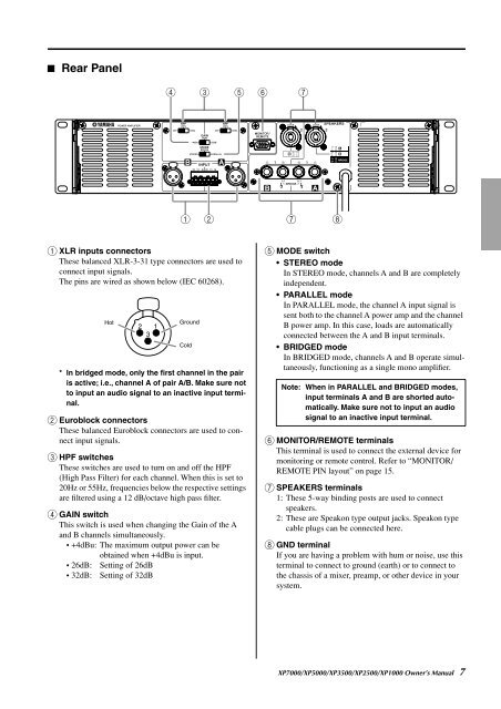
■ Rear Panel<br />
4<br />
3<br />
5<br />
6<br />
7<br />
1 2<br />
7<br />
8<br />
1 XLR inputs connectors<br />
These balanced XLR-3-31 type connectors are used to<br />
connect input signals.<br />
The pins are wired as shown below (IEC 60268).<br />
Hot<br />
Ground<br />
Cold<br />
* In bridged mode, only the first channel in the pair<br />
is active; i.e., channel A of pair A/B. Make sure not<br />
to input an audio signal to an inactive input terminal.<br />
2 Euroblock connectors<br />
These balanced Euroblock connectors are used to connect<br />
input signals.<br />
3 HPF switches<br />
These switches are used to turn on and off the HPF<br />
(High Pass Filter) for each channel. When this is set to<br />
20Hz or 55Hz, frequencies below the respective settings<br />
are filtered using a 12 dB/octave high pass filter.<br />
4 GAIN switch<br />
This switch is used when changing the Gain of the A<br />
and B channels simultaneously.<br />
• +4dBu: The maximum output power can be<br />
obtained when +4dBu is input.<br />
• 26dB: Setting of 26dB<br />
• 32dB: Setting of 32dB<br />
5 MODE switch<br />
• STEREO mode<br />
In STEREO mode, channels A and B are completely<br />
independent.<br />
• PARALLEL mode<br />
In PARALLEL mode, the channel A input signal is<br />
sent both to the channel A power amp and the channel<br />
B power amp. In this case, loads are automatically<br />
connected between the A and B input terminals.<br />
• BRIDGED mode<br />
In BRIDGED mode, channels A and B operate simultaneously,<br />
functioning as a single mono amplifier.<br />
Note: When in PARALLEL and BRIDGED modes,<br />
input terminals A and B are shorted automatically.<br />
Make sure not to input an audio<br />
signal to an inactive input terminal.<br />
6 MONITOR/REMOTE terminals<br />
This terminal is used to connect the external device for<br />
monitoring or remote control. Refer to “MONITOR/<br />
REMOTE PIN layout” on page 15.<br />
7 SPEAKERS terminals<br />
1: These 5-way binding posts are used to connect<br />
speakers.<br />
2: These are Speakon type output jacks. Speakon type<br />
cable plugs can be connected here.<br />
8 GND terminal<br />
If you are having a problem with hum or noise, use this<br />
terminal to connect to ground (earth) or to connect to<br />
the chassis of a mixer, preamp, or other device in your<br />
system.<br />
<strong>XP7000</strong>/XP5000/XP3500/XP2500/XP1000 Owner’s <strong>Manual</strong> 7