Design Type 810. Aufbau Typ 810.
Design Type 810. Aufbau Typ 810.
Design Type 810. Aufbau Typ 810.

Create successful ePaper yourself
Turn your PDF publications into a flip-book with our unique Google optimized e-Paper software.
6<br />
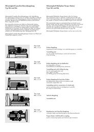
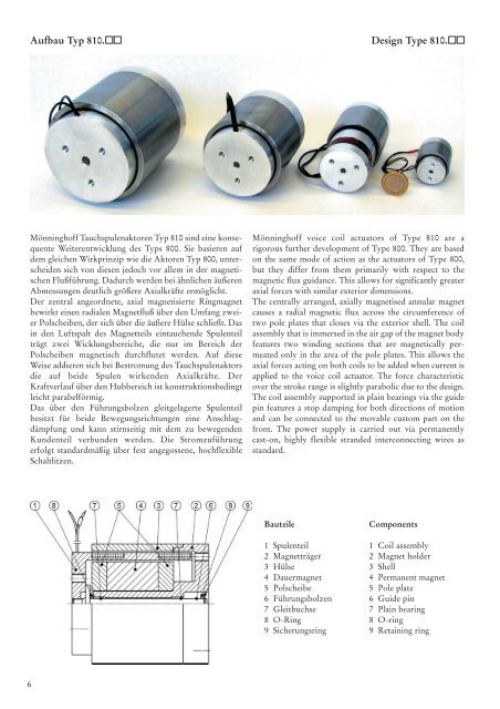
<strong>Aufbau</strong> <strong>Typ</strong> <strong>810.</strong><br />
Mönninghoff Tauchspulenaktoren <strong>Typ</strong> 810 sind eine konsequente<br />
Weiterentwicklung des <strong>Typ</strong>s 800. Sie basieren auf<br />
dem gleichen Wirkprinzip wie die Aktoren <strong>Typ</strong> 800, unterscheiden<br />
sich von diesen jedoch vor allem in der magnetischen<br />
Flußführung. Dadurch werden bei ähnlichen äußeren<br />
Abmessungen deutlich größere Axialkräfte ermöglicht.<br />
Der zentral angeordnete, axial magnetisierte Ringmagnet<br />
bewirkt einen radialen Magnetfluß über den Umfang zweier<br />
Polscheiben, der sich über die äußere Hülse schließt. Das<br />
in den Luftspalt des Magnetteils eintauchende Spulenteil<br />
trägt zwei Wicklungsbereiche, die nur im Bereich der<br />
Polscheiben magnetisch durchflutet werden. Auf diese<br />
Weise addieren sich bei Bestromung des Tauchspulenaktors<br />
die auf beide Spulen wirkenden Axialkräfte. Der<br />
Kraftverlauf über den Hubbereich ist konstruktionsbedingt<br />
leicht parabelförmig.<br />
Das über den Führungsbolzen gleitgelagerte Spulenteil<br />
besitzt für beide Bewegungsrichtungen eine Anschlagdämpfung<br />
und kann stirnseitig mit dem zu bewegenden<br />
Kundenteil verbunden werden. Die Stromzuführung<br />
erfolgt standardmäßig über fest angegossene, hochflexible<br />
Schaltlitzen.<br />
Bauteile<br />
1 Spulenteil<br />
2 Magnetträger<br />
3 Hülse<br />
4 Dauermagnet<br />
5 Polscheibe<br />
6 Führungsbolzen<br />
7 Gleitbuchse<br />
8 O-Ring<br />
9 Sicherungsring<br />
<strong>Design</strong> <strong><strong>Typ</strong>e</strong> <strong>810.</strong><br />
Mönninghoff voice coil actuators of <strong><strong>Typ</strong>e</strong> 810 are a<br />
rigorous further development of <strong><strong>Typ</strong>e</strong> 800. They are based<br />
on the same mode of action as the actuators of <strong><strong>Typ</strong>e</strong> 800,<br />
but they differ from them primarily with respect to the<br />
magnetic flux guidance. This allows for significantly greater<br />
axial forces with similar exterior dimensions.<br />
The centrally arranged, axially magnetised annular magnet<br />
causes a radial magnetic flux across the circumference of<br />
two pole plates that closes via the exterior shell. The coil<br />
assembly that is immersed in the air gap of the magnet body<br />
features two winding sections that are magnetically permeated<br />
only in the area of the pole plates. This allows the<br />
axial forces acting on both coils to be added when current is<br />
applied to the voice coil actuator. The force characteristic<br />
over the stroke range is slightly parabolic due to the design.<br />
The coil assembly supported in plain bearings via the guide<br />
pin features a stop damping for both directions of motion<br />
and can be connected to the movable custom part on the<br />
front. The power supply is carried out via permanently<br />
cast-on, highly flexible stranded interconnecting wires as<br />
standard.<br />
Components<br />
1 Coil assembly<br />
2 Magnet holder<br />
3 Shell<br />
4 Permanent magnet<br />
5 Pole plate<br />
6 Guide pin<br />
7 Plain bearing<br />
8 O-ring<br />
9 Retaining ring
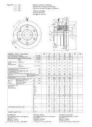
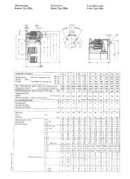
Technische Daten <strong>Typ</strong> <strong>810.</strong><br />
Baugröße / Size. 05 13 15 21<br />
Hub / Stroke H [mm] 5 5 10 10<br />
Nennkraft / Nominal force FN [N] 5,7 23,0 59,5 125<br />
Strom bei Nennkraft / Current at nominal force IN [A] 2,2 3,1 4,2 4,1<br />
Max. Leistung bei Nennkraft / Max. input power at nominal force PNmax [W] 19,6 39,0 66,3 88,8<br />
Spitzenkraft (10s) / Peak force (10s) FS [N] 15,8 66,7 142,5* 281**<br />
Strom bei Spitzenkraft / Current at peak force IS [A] 6,0 9,0 10,0 10,0<br />
Max. Leistung bei Spitzenkraft /Max input power at peak force PSmax [W] 145 329 376 528<br />
Elektr. Widerstand bei 20°C / DC resistance at 20°C R20 [Ω] 2,68 2,69 2,49 3,50<br />
Elektr. Widerstand bei 150°C / DC resistance at 150°C R150 [Ω] 4,04 4,06 3,76 5,28<br />
Thermischer Widerstand / Thermal resistance Rth [°C/W] 6,6 3,3 2,0 1,5<br />
Induktivität / Inductance L [mH] 0,36 0,54 0,69 1,55<br />
Kraftkonstante / Force constant KFI [N/A] 2,59 7,42 14,17 30,49<br />
Induktionskonstante / Back EMF constant Kind [V/(m/s)] 1,93 6,08 12,6 25,7<br />
Elektr. Zeitkonstante / Electrical time constant τel [µs] 134 202 278 442<br />
Mech. Zeitkonstante / Mechanical time constant τme [ms] 14,5 5,9 3,3 2,3<br />
Masse Spulenteil / Coil mass msp [g] 27 99 240 510<br />
Gesamtmasse / Total mass mges [g] 100 477 1330 3000<br />
Abmessungen / Dimensions [mm] D 30 50 70 90<br />
D1 24,6 42 60 78<br />
Kraft / Force [N]<br />
140<br />
120<br />
100<br />
80<br />
60<br />
40<br />
20<br />
<strong>810.</strong>05<br />
<strong>810.</strong>13<br />
0<br />
0 0,5 1 1,5 2 2,5 3 3,5 4 4,5<br />
Strom / Current [A]<br />
<strong>810.</strong>21<br />
<strong>810.</strong>15<br />
d1<br />
d2 M3 M4 M5 M6<br />
d3<br />
d4 M3 M4 M5 M6<br />
L 40 60 80 100<br />
l2 31,8 49 68,5 86,3<br />
l2 l3 6 7,5 8 9,5<br />
l4 4,5 6,5 8 8<br />
Hinweise:<br />
Daten basierend auf 20°C Umgebungstemperatur,150°C<br />
Spulentemperatur bei Befestigung des feststehenden Magnetteils<br />
auf einer massiven Metallplatte. Bei anderen Einbaubedingungen<br />
ist kundenseitig sicherzustellen, dass die Spulentemperatur 150°C<br />
nicht überschreitet.<br />
Kräfte in Mittelstellung des Spulenteils (Position H/2)<br />
* 40s Spitzenkraft<br />
** 15s Spitzenkraft<br />
Kennlinien / Characteristics<br />
Kraft / Force [N]<br />
140<br />
120<br />
100<br />
80<br />
60<br />
Technical Data <strong><strong>Typ</strong>e</strong> <strong>810.</strong><br />
Notes:<br />
Data based on 20°C environmental temperature, 150°C coil temperature<br />
when steady magnet assembly is attached to a massive<br />
metal plate. In case of different mounting conditions customer<br />
has to care that coil temperatur of 150°C is not<br />
exceeded.<br />
Forces in mid stroke position<br />
* 40s peak force<br />
** 15s peak force<br />
14<br />
2x180°<br />
22<br />
2x180°<br />
25<br />
3x120°<br />
35<br />
3x120°<br />
<strong>810.</strong>21<br />
<strong>810.</strong>15<br />
30<br />
3x120°<br />
55<br />
3x120°<br />
40<br />
20<br />
<strong>810.</strong>13<br />
0<br />
<strong>810.</strong>05<br />
0 1 2 3 4 5 6 7 8 9 10<br />
Hub / Stroke [mm]<br />
40<br />
3x120°<br />
70<br />
3x120°<br />
Weitere Ausführungen mit anderen Hüben und Nennkräften bis 200 N auf Anfrage.<br />
Additional designs with different strokes and nominal forces up to 200 N on request.<br />
7