VLF/LF Loop Antenna System Submarine Communications
VLF/LF Loop Antenna System Submarine Communications
VLF/LF Loop Antenna System Submarine Communications
- No tags were found...

You also want an ePaper? Increase the reach of your titles
YUMPU automatically turns print PDFs into web optimized ePapers that Google loves.
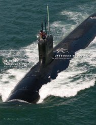
Photo: HDW<br />
<strong>V<strong>LF</strong></strong>/<strong>LF</strong> <strong>Loop</strong> <strong>Antenna</strong> <strong>System</strong><br />
<strong>Submarine</strong> <strong>Communications</strong>
<strong>V<strong>LF</strong></strong>/<strong>LF</strong><br />
<strong>Loop</strong> <strong>Antenna</strong> <strong>System</strong><br />
<strong>Submarine</strong><br />
<strong>Communications</strong><br />
The ability of very low and<br />
low frequency transmissions to penetrate<br />
seawater allows a fully submerged<br />
submarine to copy strategic and<br />
tactical communications. For that reason,<br />
<strong>V<strong>LF</strong></strong>/<strong>LF</strong> communication has been used<br />
as prime submarine broadcast for many<br />
decades.<br />
The most common antenna type<br />
used for receiving <strong>V<strong>LF</strong></strong>/<strong>LF</strong> transmissions<br />
is the crossed-loop antenna. Although<br />
more advanced <strong>V<strong>LF</strong></strong>/<strong>LF</strong> receiving<br />
antennas, such as buoyant wires, are<br />
available today, virtually all submarines<br />
in service are equipped with a crossed<br />
loop antenna.<br />
Lockheed Martin has long<br />
been the leader in the field of loop<br />
antenna systems, having designed<br />
and manufactured many of the loop<br />
antennas in service today. We offer a<br />
standard, high quality submarine loop<br />
antenna system that is in service on<br />
Photo: HDW<br />
many submarines worldwide. We also<br />
offer the capability of providing custom<br />
<strong>V<strong>LF</strong></strong>/<strong>LF</strong> receiving antennas for maritime,<br />
air and ground applications, and to fit the<br />
specific performance and/or installation<br />
mounting requirements of our<br />
customers.<br />
The <strong>V<strong>LF</strong></strong>/<strong>LF</strong> <strong>Antenna</strong>/<br />
Preamplifier, is designed<br />
to mount atop or within<br />
the fin of the submarine.<br />
All of the <strong>V<strong>LF</strong></strong>/<strong>LF</strong> loop antenna systems provided by<br />
Lockheed Martin are comprised of five units —<br />
Unit 1<br />
The <strong>V<strong>LF</strong></strong>/<strong>LF</strong> <strong>Antenna</strong>/Preamplifier, is<br />
designed to mount atop or within the fin<br />
of the submarine. It can be provided with<br />
or without a fiberglass fairing. The <strong>V<strong>LF</strong></strong>/<br />
<strong>LF</strong> <strong>Antenna</strong>/Preamplifier is comprised<br />
of a ferrite loaded, crossed loop antenna<br />
and a matched set of <strong>V<strong>LF</strong></strong>/<strong>LF</strong> low noise<br />
preamplifiers. One loop is oriented in the<br />
fore-aft (F/A) direction of the ship and<br />
the other in the athwartship (ATH)<br />
direction. The <strong>V<strong>LF</strong></strong>/<strong>LF</strong> signals receive<br />
patterns on the loop antennas in the form<br />
of orthogonal figure-eights. These signals<br />
are preamplified by matched low noise<br />
amplifiers which are housed in an<br />
electronics cavity located at the center<br />
of the antenna. The crossed loop antenna<br />
is in the shape of a picture frame<br />
and it surrounds the electronics cavity.<br />
The crossed loop antenna is fully<br />
encapsulated for environmental<br />
protection while the preamplifiers<br />
are accessible through an access port<br />
at the top of the watertight electronics<br />
cavity. The balanced output of each<br />
matched loop preamplifier is provided<br />
at a single, watertight connector<br />
located at the bottom of the <strong>Antenna</strong>/<br />
Preamplifier Unit.<br />
Unit 2<br />
The Outboard Transmission Line, is<br />
a shielded, waterblocked cable that<br />
carries the RF signals from the outboard<br />
<strong>Antenna</strong>/Preamplifier to the inboard<br />
Amplifier/Combiner.<br />
Unit 3<br />
The Hull Penetrator, provides the<br />
electrical connection through the<br />
submarine pressure hull. This penetrator<br />
is of the M24231 type and is sub-safe<br />
certified. If specified by the customer,<br />
other hull penetrator types can be supplied.<br />
A stuffing tube can be used in lieu of<br />
a penetrator if the customer so desires.
Specifications<br />
Performance<br />
Outputs (Two Provided)<br />
Frequency Band<br />
Omni-Azmuthal Response<br />
<strong>System</strong> Effective Height (Omni)<br />
<strong>System</strong> Effective Height (Bi-Directional)<br />
Sensitivity (Omni)<br />
Sensitivity (Bi-Directional)<br />
Output Impedance<br />
Maximum Output<br />
<strong>Antenna</strong><br />
<strong>Loop</strong>s<br />
Preamplifier<br />
<strong>Antenna</strong> Nulls<br />
Amplifier/Combiner<br />
Input Power<br />
Balanced, 50 Ohm, Omni-Azimuthal Pattern<br />
10 - 160 kHz (Usable through 1.5 MHz)<br />
Better than 1.5 dB from 10 - 160 kHz through<br />
360° of Azimuth<br />
1.0 Meter Nominal into 50 Ohms<br />
0.5 Meters Nominal into 50 Ohms<br />
Better than 0.26 μV/m/Hz 1/2 - 10 - 20 kHz<br />
Better than 0.14 μV/m/Hz 1/2 - 20 - 160 kHz<br />
Better than 0.2 μV/m/Hz 1/2 - 10 - 20 kHz<br />
Better than 0.12 μV/m/Hz 1/2 - 20 - 160 kHz<br />
50 ohms Nominal<br />
0.1 VRMS Open Circuit for<br />
Less Than 1 Percent Total Harmonic Distortion<br />
Ferrite Loaded, Crossed <strong>Loop</strong>s, Oriented<br />
Fore-Aft and Athwartships (Displaced by<br />
90° from Each Other)<br />
Two Identical (F/A and ATH) Located Integral<br />
to the <strong>Antenna</strong><br />
Greater than 40 db<br />
115 VAC, 50/60 Hz, 10 Watts Nominal<br />
Lockheed Martin<br />
offers a standard,<br />
high quality<br />
submarine loop<br />
antenna system<br />
that is in service<br />
on many<br />
submarines<br />
worldwide.<br />
<strong>Antenna</strong>/Preamplifier<br />
without fairing.<br />
The <strong>V<strong>LF</strong></strong>/<strong>LF</strong> <strong>Antenna</strong>/Preamplifier can be provided<br />
with or without fiberglass fairing.<br />
<strong>Antenna</strong>/Preamplifier<br />
with fairing.<br />
Unit 4<br />
The Inboard Transmission Line, is<br />
the same cable type that is used for the<br />
outboard Transmission Line. Watertight<br />
connectors are not used inboard.<br />
Unit 5<br />
The Amplifier/Combiner, is located<br />
in the submarine radio room and<br />
provides the interface between the<br />
unique <strong>Antenna</strong>/Preamplifier and<br />
standard shipboard receivers. It<br />
contains low noise amplifiers, an<br />
omni-azimuthal pattern generator,<br />
output drivers and the required power<br />
supplies for both inboard and outboard<br />
use. The preamplified <strong>V<strong>LF</strong></strong>/<strong>LF</strong> signals<br />
from the <strong>Antenna</strong>/Preamplifier arrive<br />
at the Amplifier/Combiner input as<br />
orthogonal figure-eights. These signals<br />
are amplified and distributed to a<br />
bi-directional 50 ohm, balanced<br />
communication output. They are also<br />
combined in an omni pattern generator<br />
to produce the omni-azimuthal signal.<br />
Separate output drivers provide this<br />
omni signal to two, balanced, 50 ohm<br />
output jacks which can be cabled to<br />
any standard <strong>V<strong>LF</strong></strong>/<strong>LF</strong> communication<br />
receiver.
©2006<br />
Lockheed Martin Corporation<br />
All Rights Reserved<br />
Lockheed Martin MS2<br />
Seven Barnabas Road<br />
Marion, MA 02738<br />
An ISO9001:2000 Company<br />
Sea-Air <strong>System</strong>s<br />
508.748.1160 (x138)<br />
e-mail: douglas.Q.williams@lmco.com<br />
OCT2006/NDCR/20060006/Covers:2006