Internal GPS Active Patch Antenna Application Note - Taoglas
Internal GPS Active Patch Antenna Application Note - Taoglas
Internal GPS Active Patch Antenna Application Note - Taoglas
- No tags were found...

Create successful ePaper yourself
Turn your PDF publications into a flip-book with our unique Google optimized e-Paper software.
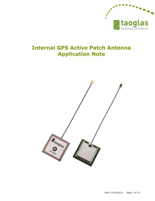
<strong>Internal</strong> <strong>GPS</strong> <strong>Active</strong> <strong>Patch</strong> <strong>Antenna</strong><br />
<strong>Application</strong> <strong>Note</strong><br />
APN-13-8-002/A Page 1 of 14
1. BASICS<br />
2. APPLICATIONS<br />
3. SIZE<br />
4. SHAPE<br />
5. GROUND PLANE<br />
6. IMPEDANCE<br />
7. BANDWIDTH<br />
8. VSWR<br />
9. LINK BUDGET<br />
10. GAIN<br />
11. NOISE FIGURE<br />
CONTENTS<br />
12. POWER CONSUMPTION<br />
13. EFFICIENCY<br />
14. POLARIZATION<br />
15. MOUNTING<br />
16. ENVIRONMENTAL CONSIDERATIONS<br />
17. TUNING<br />
18. ISOLATION<br />
19. CABLE & CONNECTOR<br />
20. SMD<br />
APN-13-8-002/A Page 2 of 14
1. BASICS<br />
An internal <strong>GPS</strong> active patch antenna with cable is used in most mobile<br />
devices today that require high signal strength in a small form factor. It is<br />
the highest performing solution of all antenna types.<br />
Usually consisting of a specially formulated dielectric ceramic, a trace is<br />
printed on the substrate to get the desired right hand circularly polarized<br />
patch antenna topology. The patch is mounted on a PCB; underneath the<br />
PCB is the Low Noise Amplifier (LNA) which amplifies the <strong>GPS</strong> signal before<br />
being transmitted through the coaxial cable and connector to the receiver.<br />
This design application note is intended to help the antenna integrator<br />
understand the relevant parameters affecting the antenna performance.<br />
<strong>Taoglas</strong> recommends that the integrator strictly follow the guidelines in this<br />
application note, upon your device prototype completion <strong>Taoglas</strong> offers<br />
further optimization by custom tuning and testing service of the antenna in<br />
your device.<br />
2. APPLICATIONS<br />
An internal <strong>GPS</strong> active antenna with cable is suitable for mobile applications<br />
or areas where internal antennas are required or where not much space or<br />
volume is available. It is ideally affixed to the plastic housing of a device<br />
directly by double-sided adhesive, screw-mounting, or slot. <strong>Taoglas</strong> internal<br />
<strong>GPS</strong> active patch antennas come in a range of sizes from 10mm to<br />
APN-13-8-002/A Page 3 of 14
3. SIZE<br />
The larger the antenna surface area (or volume), in general the higher the<br />
performance in terms of gain and radiation characteristics.<br />
4. SHAPE AND PROFILE<br />
<strong>GPS</strong> internal active patch antennas are usually square in dimension. Overall<br />
height profiles range from 4mm for our slimmest, to 7mm for bulkier<br />
designs.<br />
APN-13-8-002/A Page 4 of 14
5. GROUND PLANE EFFECTS<br />
The larger the ground-plane, the higher the antenna gain in general. Also<br />
the centre frequency of the antenna will change depending on the size of<br />
the ground-plane. The individual patches on <strong>Taoglas</strong> active patch antennas<br />
can be tuned to take into account these changes.<br />
Graph of 18.5mm <strong>Patch</strong> Centre Frequency shift with Ground-plane size<br />
6. IMPEDANCE<br />
RF circuits in mobile devices should be designed for 50 Ohm characteristic<br />
impedance at the source (RF module), transmission line (PCB trace or coax<br />
cable) and load (antenna). So we will usually match the antenna for 50<br />
Ohm impedance.<br />
7. BANDWIDTH<br />
The effective bandwidth of a <strong>GPS</strong> antenna is usually measured by the<br />
frequency band below -10dB return loss. A <strong>GPS</strong> ceramic patch bandwidth<br />
narrows with size.<br />
Typical bandwidths for <strong>GPS</strong> patches are as follows<br />
25*25*4 mm 20 MHz<br />
18*18*4 mm 10 Mhz<br />
15*15*4 mm 8 Mhz<br />
12*12*4 mm 7 MHz<br />
10*10*4 mm 5 MHz<br />
APN-13-8-002/A Page 5 of 14
Therefore the smaller the antenna, the more chance it will have that<br />
frequency shifts in the device will cause it to perform very poorly, thus<br />
necessitating that the antenna bandwidth be retuned to have the effective<br />
bandwidth at the <strong>GPS</strong> 1.5754 GHz frequency.<br />
8. VSWR<br />
In principle the target is to be below 2.0, ideally below 1.5.<br />
9. LINK BUDGET<br />
We use a table called a link budget to determine what antenna gain we<br />
need for a given application.<br />
<strong>GPS</strong> Link Budget Analysis - Example<br />
Where do we get this from We need to discuss the <strong>GPS</strong> system attributes<br />
The <strong>GPS</strong> satellites orbit the earth with a speed of 3.9km per second and<br />
have a circulation time of 12 h sidereal time, corresponding to 11h 58min<br />
APN-13-8-002/A Page 6 of 14
earth time. This means that the same satellite reaches a certain position<br />
about 4 minutes earlier each day. The mean distance from the middle of the<br />
earth is 26560 km. With a mean earth radius of 6360 km, the height of the<br />
orbits is then about 20200 km. Orbits in this height are referred to as<br />
MEO – medium earth orbit. In comparison, geostationary satellites like<br />
ASTRA or Meteosat – satellites orbit the earth at 42300 km, which is about<br />
twice the distance of <strong>GPS</strong> satellites.<br />
This long distance creates multipath issues. Multipath occurs when waves<br />
emitted by the transmitter travel along a different path and interfere<br />
destructively with waves travelling on a direct line-of-sight path. This is<br />
sometimes referred to as signal fading. This phenomenon occurs because<br />
waves travelling along different paths may be completely out of phase when<br />
they reach the antenna, thereby cancelling each other.<br />
So the amount of extra RF power radiated to overcome this phenomenon is<br />
referred to as fade margin. The exact amount of fade margin required<br />
depends on the desired reliability of the link, but a good rule-of-thumb is<br />
20dB to 30dB. This is the number we always want to reach and which we<br />
work backwards from when calculating the link budget.<br />
We can see that the three controllable variables in this budget are the RF<br />
component losses, the antenna gain, and the receiver sensitivity or “noise<br />
level”. By manipulating these three variables we can preserve the total fade<br />
margin to enable a strong <strong>GPS</strong> signal lock. A lower gain antenna would<br />
need a higher receiver sensitivity, conversely a low sensitivity receiver<br />
would require a higher gain antenna.<br />
10. GAIN<br />
We can separate the gain of an active <strong>GPS</strong> antenna into two parts.<br />
First is the passive gain. This has the most effect on the intrinsic<br />
performance of the antenna. The passive gain of the antenna is closely<br />
linked to the surface area or volume of the antenna. The larger the surface<br />
area or volume of the antenna, the higher the gain. Care must be taken<br />
that clearances of minimum 4mm are kept from other metal components in<br />
the device or metallised substances which will obstruct the electro-magnetic<br />
radiation, substantially reducing the gain. Also the larger the ground-plane<br />
of the antenna the more the gain.<br />
APN-13-8-002/A Page 7 of 14
Gain of the antenna is chiefly determined by the directionality of the<br />
antenna and the surface area.<br />
A <strong>GPS</strong> patch antenna has high gain towards the zenith (highest point in the<br />
sky), and gradually decreasing gain towards the horizon. This is actually an<br />
advantage compared to antennas that have their gain distributed in a fully<br />
Omni-directional pattern. As the more Omni-directional an antenna, the<br />
worse it’s average gain in any position. The reason patch antennas are most<br />
popular than helical or chip antennas is precisely because they deliver<br />
maximum gain towards one hemi-sphere, i.e. the sky. Up to 5dBi towards<br />
the highest point of the sky. Whereas a helical or chip antenna will deliver<br />
something like -3~-5dBi in most directions (in fact it also has areas it has<br />
null points), that is a huge drop in overall sensitivity.<br />
Typical peak gain for <strong>GPS</strong> patch antennas on standardized ground planes<br />
are following.<br />
25mm <strong>Patch</strong><br />
18mm <strong>Patch</strong><br />
15mm <strong>Patch</strong><br />
12mm <strong>Patch</strong><br />
10mm <strong>Patch</strong><br />
5 dBi<br />
2dBi<br />
1dBi<br />
0.5 dBi<br />
-2 dBi<br />
Graph of 18.5mm <strong>Patch</strong> Gain vs. Size of Ground Plane<br />
APN-13-8-002/A Page 8 of 14
A larger ground plane will increase the gain of the antenna. Conversely,<br />
longer cable lengths or more lossy cables will decrease the gain of the<br />
antenna.<br />
Second is the active gain. In this sense gain is the ratio of input to output<br />
power. Typical <strong>GPS</strong> LNAs use two or three gain blocks and yield 25 dB to 50<br />
dB of gain depending on the user’s requirement. Unlike NF, a low or high<br />
gain does not indicate a good or bad LNA. It is important to specify the<br />
amount of gain that is required rather than to go for the highest available<br />
gain: more gain will produce more inter-modulation products in LNA and<br />
receiver. Not enough gain can cause the <strong>GPS</strong> signal to be below the MDS<br />
level of the <strong>GPS</strong> receiver.<br />
One stage LNA active antennas are enough for most <strong>GPS</strong> applications<br />
nowadays that use the latest generation <strong>GPS</strong> receivers.<br />
Two stage LNA active antennas are usually used where the cable is<br />
relatively long, longer than 200mm, to compensate for attenuation in the<br />
cable and effects of noise in the environment. Or with older <strong>GPS</strong> receivers<br />
with less sensitivity or no in-built LNA. Even when a two stage LNA active<br />
antenna is used with the latest receivers it will usually not saturate the<br />
signal as most of the latest receivers have automatic gain control.<br />
Three stage LNA active antennas are used for longer RG-174 cable lengths<br />
up to 8M.<br />
For applications that require longer cable length than 8M, an in-line <strong>GPS</strong><br />
amplifier is needed every 10 metres or so to boost the signal.<br />
11. NOISE FIGURE (NF)<br />
Noise Figure is a ratio that indicates how much noise power the LNA will<br />
contribute to the total receiver noise. The Minimum Discernable Signal<br />
(MDS) is the weakest signal a receiver can decode. The more noise the LNA<br />
contributes, the higher the noise floor and the less sensitive the receiver is.<br />
At the systems level, a poor LNA degrades the MDS. While LNA NF is not<br />
the only factor that drives the MDS, it is an important consideration since<br />
APN-13-8-002/A Page 9 of 14
the noise figure of the first stage in a receiver chain is the single largest<br />
contributor to the system noise figure. A typical state of the art, single<br />
stage commercial grade LNA at LBand (<strong>GPS</strong>) has a noise figure between 0.5<br />
and 1 dB. A multistage <strong>GPS</strong> LNA with filtering has a noise figure between<br />
1.0 and 2.5 dB. <strong>Taoglas</strong> active patch antennas have a noise figure between<br />
1.0 to 1.5dB.<br />
12. POWER CONSUMPTION<br />
Power consumption is the current flowing through the LNA multiplied by the<br />
voltage coming out of the coax line. LNA typically have their current<br />
specified. For a typical single stage LNA, the current is between 2mA and<br />
100mA or more. <strong>Taoglas</strong> LNAs typically have a power consumption of 3mA<br />
for one stage LNAs, and 8~13mA for two stage LNAs.<br />
13. EFFICIENCY<br />
Efficiency is a good overall measurement of an omni-directional antenna for<br />
mobile communication systems such as GSM and WLAN. It is less of a good<br />
measurement for <strong>GPS</strong> as ideally the <strong>GPS</strong> antenna in a device is pointing<br />
towards the sky. It is better to look at the actual radiation pattern of the<br />
top hemisphere of the patch antenna to understand its true performance<br />
characteristics.<br />
14. POLARIZATION<br />
Polarization describes the orientation of the wave oscillation. The radiation<br />
transmitted from <strong>GPS</strong> satellites is circularly polarized. An antenna designed<br />
for <strong>GPS</strong> reception should always be circularly polarized. Our internal <strong>GPS</strong><br />
active patch antennas are circularly polarized. The reason other competing<br />
technologies like chip, metal or printed PCB circuit antennas have such poor<br />
<strong>GPS</strong> performance is they are all linearly polarized. In effect their sensitivity<br />
is reduced by 50% compared to a <strong>GPS</strong> active patch antenna, which causes<br />
major difficulty to acquire a <strong>GPS</strong> lock in urban areas.<br />
APN-13-8-002/A Page 10 of 14
15. MOUNTING<br />
<strong>Taoglas</strong> internal <strong>GPS</strong> active patch antennas like all <strong>GPS</strong> antennas should be<br />
ideally placed with a line of sight to the sky. The antenna should be placed<br />
on the top of the device below the plastic housing, without metal close to it.<br />
The antenna cable should not be more than 200mm so as to minimize<br />
attenuation to the receiver. The cable should not be bent more than 30<br />
degrees and should be routed away from noisy components such as ICs.<br />
16. ENVIRONMENTAL CONSIDERATIONS<br />
Close proximity to components or housing affects the electrical performance<br />
of all antennas. When placed on a non-conductive area of the board, in<br />
most cases ideally there should be clearance of 5mm in all directions from<br />
the board/housing for maximum efficiency. A reduction in the gain of the<br />
antenna efficiency and shift in tuned frequency will be observed if these<br />
clearances are not adhered to. Proximity effects will also have an adverse<br />
effect on the radiation pattern of the antenna. Device housings should<br />
never be metal or have metal materials.<br />
17. TUNING<br />
<strong>GPS</strong> <strong>Patch</strong> antennas should be tuned to their ground-plane that they are<br />
mounted on and taking into account the frequency shifts due to the specific<br />
device environment the antenna finds itself in. This is done in our state of<br />
the art laboratories and anechoic chambers<br />
17.1 Impedance matching<br />
The antenna will be tuned to get close to 50 Ohm match on the Smith Chart<br />
when in the device. The S11 return loss magnitude is also looked at and the<br />
industry standard is
The antenna is physically tuned a number of ways, the shape of the top<br />
silver electrode can be changed, or the feed-point can be moved.<br />
17.2 Radiation Pattern and Gain Testing<br />
Radiation patterns of the antennas X-Y and Y-Z planes are taken in the<br />
device.<br />
This corresponds to two vertical cuts of an “apple” type pattern which is the<br />
typical pattern of a <strong>GPS</strong> patch antenna at cross angles to each other. Where<br />
they intersect we can then take their point readings at 0deg/180 deg<br />
horizontal to have four points of reference for the horizontal radiation<br />
pattern and drawing a line through them we can now solve to produce the<br />
horizontal radiation pattern of the radiation thereby giving us a 3D view of<br />
the radiation pattern. These radiation patterns tells us the most important<br />
information about the real-life antenna performance in the field such as the<br />
antenna’s ability to receive signals from satellites at low altitudes, or to be<br />
able to compare relative performance of one antenna against another. The<br />
below patterns are taken from scans of a 25mm*25mm*2mm patch on an<br />
extended 35mm ground-plane.<br />
APN-13-8-002/A Page 12 of 14
XZ Plane1575.42 MHz<br />
YZ Plane 1575.42 MHz<br />
18. ISOLATION<br />
Isolation is a measure of coupling between two different antennas. The<br />
inherently low power <strong>GPS</strong> signal is susceptible to interference from much<br />
higher power cellular or Wi-Fi radiation in the device. Therefore <strong>GPS</strong><br />
antenna should be placed as far as possible away from the other antennas<br />
in the device.<br />
The two antennas cables should not cross over or come close to the other’s<br />
antenna.<br />
Testing is carried by sending a signal in one antenna and measuring the<br />
power of the signal at the other antenna. There should be a 10dB or more<br />
difference between the transmit and the receive signal. The easiest method<br />
is to keep moving the two antennas farther from each other until the target<br />
isolation is achieved.<br />
APN-13-8-002/A Page 13 of 14
19. CABLE & CONNECTOR<br />
Ø1.13mm diameter micro coax cable is preferred in most cellular antenna<br />
projects as most economical solution. Cable loss is not a big factor if cable<br />
length is kept below 150mm.<br />
The cable needs good grounding. If the body of the cable is near the ground<br />
of the device the cable should be as near as possible to the device ground.<br />
The cable should not be looped because it will cause frequency shifts and<br />
also create magnetic field which will interact with the main antenna<br />
magnetic field.<br />
The cable should be kept away from emitting components such as LCD<br />
driver chip or CPU.<br />
It is preferred to use connectors on the cables for higher reliability in<br />
connection over solder. Most economical connector solution is IPEX line of<br />
connectors which is compatible with Hirose industry standards U.FL and<br />
W.FL. <strong>Taoglas</strong> offers any cable and connector solution for the integrator.<br />
<strong>Taoglas</strong> also offers the on-board mating connector and cable jumpers.<br />
20. SMD<br />
<strong>Taoglas</strong> now offers the industries first SMD internal <strong>GPS</strong> active patch<br />
antennas. These provide lowest loss solution and enable automated<br />
assembly increasing accuracy and reliability of integration and eliminating<br />
labour costs of mounting and connection.<br />
APN-13-8-002/A Page 14 of 14