Multi-Channel Coherent PM-QPSK InP Transmitter ... - Infinera
Multi-Channel Coherent PM-QPSK InP Transmitter ... - Infinera
Multi-Channel Coherent PM-QPSK InP Transmitter ... - Infinera
- No tags were found...

You also want an ePaper? Increase the reach of your titles
YUMPU automatically turns print PDFs into web optimized ePapers that Google loves.
<strong>Multi</strong>-<strong>Channel</strong> <strong>Coherent</strong> <strong>PM</strong>-<strong>QPSK</strong> <strong>InP</strong> <strong>Transmitter</strong><br />
Photonic Integrated Circuit (PIC) Operating At 112 Gb/s<br />
Per Wavelength<br />
P. Evans, M. Fisher, R. Malendevich, A. James, P. Studenkov, G. Goldfarb, T. Vallaitis, M. Kato, P. Samra,<br />
S. Corzine, E. Strzelecka, R. Salvatore, F. Sedgwick, M. Kuntz, V. Lal, D. Lambert, A. Dentai, D. Pavinski,<br />
J. Zhang, B. Behnia, J. Bostak, V. Dominic, A. Nilsson, B. Taylor, J. Rahn, S. Sanders, H. Sun, K.-T. Wu,<br />
J. Pleumeekers, R. Muthiah, M. Missey, R. Schneider, J. Stewart, M. Reffle, T. Butrie, R. Nagarajan,<br />
C. Joyner, M. Ziari, F. Kish, and D. Welch<br />
<strong>Infinera</strong> Corporation, 169 Java Drive, Sunnyvale, CA 94089 USA<br />
e-mail: pevans@infinera.com<br />
1. Introduction<br />
Abstract: A 10-wavelength, polarization-multiplexed, monolithically integrated <strong>InP</strong> transmitter<br />
PIC is demonstrated for the first time to operate at 112 Gb/s per wavelength with a coherent<br />
receiver PIC.<br />
OCIS codes: (250.5300) Photonic integrated circuits; (060.5060) Phase modulation; (060.1660) <strong>Coherent</strong> communications;<br />
Photonic integration is critical to realizing large-scale, high-efficiency, phase-sensitive modulation schemes based<br />
on coherent detection. We have previously reported transmitter PIC operation at 40 Gb/s D<strong>QPSK</strong> at 20 Gbaud [1]<br />
and later with polarization multiplexing at 10 Gbaud [2]. In this paper, we describe the first demonstration of a<br />
coherent <strong>PM</strong>-<strong>QPSK</strong>, 10-wavelength transmitter PIC. This architecture is enabled by integration of 10 narrow<br />
linewidth tunable lasers. We report on operation of a packaged module pair at 57 Gb/s per wavelength and a chip at<br />
112 Gb/s per wavelength.<br />
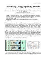
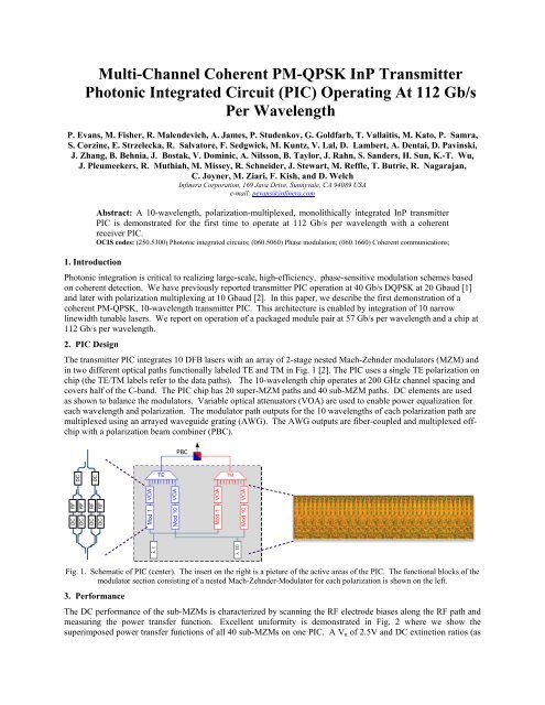
2. PIC Design<br />
The transmitter PIC integrates 10 DFB lasers with an array of 2-stage nested Mach-Zehnder modulators (MZM) and<br />
in two different optical paths functionally labeled TE and TM in Fig. 1 [2]. The PIC uses a single TE polarization on<br />
chip (the TE/TM labels refer to the data paths). The 10-wavelength chip operates at 200 GHz channel spacing and<br />
covers half of the C-band. The PIC chip has 20 super-MZM paths and 40 sub-MZM paths. DC elements are used<br />
as shown to balance the modulators. Variable optical attenuators (VOA) are used to enable power equalization for<br />
each wavelength and polarization. The modulator path outputs for the 10 wavelengths of each polarization path are<br />
multiplexed using an arrayed waveguide grating (AWG). The AWG outputs are fiber-coupled and multiplexed offchip<br />
with a polarization beam combiner (PBC).<br />
PBC<br />
DC<br />
DC<br />
DC<br />
DC<br />
RF<br />
RF<br />
RF<br />
RF<br />
DC<br />
DC<br />
Fig. 1. Schematic of PIC (center). The insert on the right is a picture of the active areas of the PIC. The functional blocks of the<br />
modulator section consisting of a nested Mach-Zehnder-Modulator for each polarization is shown on the left.<br />
3. Performance<br />
The DC performance of the sub-MZMs is characterized by scanning the RF electrode biases along the RF path and<br />
measuring the power transfer function. Excellent uniformity is demonstrated in Fig. 2 where we show the<br />
superimposed power transfer functions of all 40 sub-MZMs on one PIC. A V π of 2.5V and DC extinction ratios (as
defined in Fig. 2a) in excess of 30dB across all sub-MZMs is achieved. These high extinction ratios imply a power<br />
imbalance between MZ arms of
Fig. 4. Polarization-multiplexed, 14.25 Gbaud constellation diagrams for all channels and polarizations of the 10×57 Gb/s<br />
transmitter PIC.<br />
The RF performance of a standalone transmitter PIC was characterized for 112 Gb/sec operation using a new<br />
PIC design wherein the MZM design was improved to operate at 28 Gbaud. In this experiment, the two RF data<br />
streams were constructed using a 28 Gb/s pattern generator with a 2 15 -1 PRBS pattern and applied to the chip using<br />
multiple ground-signal-signal-ground RF probes. The RF signal was applied first to the TE and then the TM<br />
polarization. The optical receiver used to characterize the device was a 10-channel receiver PIC module [3]. For<br />
each polarization, the optical signal was split, delayed and recombined to generate polarization-multiplexed inputs to<br />
the receiver module. Figure 5 shows the back-to-back constellation diagram for four data streams at 28 Gbaud per<br />
stream, or 112 Gb/s per wavelength across half of the C-band. Again, operation better than the FEC limit was<br />
demonstrated.<br />
Fig. 5. 28 Gbaud constellation diagrams for each polarization of wavelengths 1 and 10 of a 10 wavelength transmitter PIC.<br />
3. Conclusion<br />
We report the first demonstration of a 10-wavelength <strong>PM</strong>-<strong>QPSK</strong> transmitter PIC running at 57 Gb/s per wavelength<br />
in a packaged module. We also demonstrate the operation of a standalone transmitter PIC chip at 112 Gb/s per<br />
wavelength in conjunction with a packaged receiver PIC. This 112 Gb/s operation demonstrates the viability of 10-<br />
wavelength <strong>InP</strong> PICs to scale to a Terabit /chip capacity and beyond.<br />
4. References<br />
[1] S. Corzine et al., “10-<strong>Channel</strong> x 40Gb/s per channel D<strong>QPSK</strong> monolithically integrated <strong>InP</strong>-based transmitter PIC,” presented at the OFC<br />
2008, Feb. 2008, Paper PDP18.<br />
[2] S. Corzine, et al., “Large-Scale <strong>InP</strong> <strong>Transmitter</strong> PICs for <strong>PM</strong>-D<strong>QPSK</strong> Fiber Transmission Systems,” IEEE PTL, Vol. 22, No. 14, p.1015, July<br />
2010.<br />
[3] R. Nagarajan et al., “10 <strong>Channel</strong>, 100Gbit/s per <strong>Channel</strong>, Dual Polarization, <strong>Coherent</strong> <strong>QPSK</strong>, Monolithic <strong>InP</strong> Receiver Photonic Integrated<br />
Circuit,” presented at the OFC 2011, Mar. 2011.