27338J DS7488 Installation Instructions.PMD
27338J DS7488 Installation Instructions.PMD
27338J DS7488 Installation Instructions.PMD
- No tags were found...

You also want an ePaper? Increase the reach of your titles
YUMPU automatically turns print PDFs into web optimized ePapers that Google loves.
<strong>DS7488</strong> Octal Relay Module<br />
<strong>Installation</strong> <strong>Instructions</strong><br />
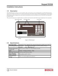
1.0 Description<br />
The <strong>DS7488</strong> is an Octal Relay Module that provides eight Form “C”<br />
relay outputs for the DS7400 Series Control/Communicators and<br />
DS9400 AddressiFire 255 Series Fire Alarm Control Panels<br />
(FACP).<br />
It connects to the panels via the options bus. The outputs are fully<br />
programmable and can be activated by several system events.<br />
Each output operates individually of the other seven outputs for<br />
complete flexibility.<br />
2.0 Specifications<br />
• Control Panel Requirements: The <strong>DS7488</strong> is designed to<br />
work with the following control panels:<br />
• A DS7400, DS7400X, DS7400Xi, DS7400Xi Rev 3 or<br />
DS7400Xi Rev 4. The control panel ROM version must be<br />
1.03 or higher.<br />
• All versions of the DS9400 AddressiFire 255 Series Fire<br />
Alarm Control Communicator.<br />
• Current Draw:<br />
• 10 mA + 40 mA for each energized relay when connected<br />
to a DS7400Xi.<br />
• When connected to a DS9400 AddressiFire 255 Series<br />
FACP, the <strong>DS7488</strong> draws 8 mA + 30 mA for each energized<br />
relay (the module operates on 12 V option bus power<br />
which is derived from the 24 V battery).<br />
• Contacts: Rated 5.0 A @ 28 VDC (maximum for resistive<br />
loads).<br />
3.0 <strong>Installation</strong><br />
3.1 DS7400Xi <strong>Installation</strong><br />
1) The <strong>DS7488</strong> should be mounted within the DS7400Xi<br />
enclosure. Install the panel enclosure as described in its<br />
Reference Guide.<br />
2) Disconnect power from the panel before installing the<br />
<strong>DS7488</strong>. This can be done by unplugging the transformer or<br />
turning off the AC supply circuit and removing the red battery<br />
lead.<br />
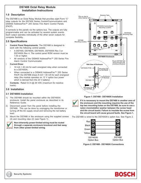
3) Mount the <strong>DS7488</strong> in the enclosure using the supplied screws<br />
(2) and mounting clips (2) (see Figure 1).<br />
Non-inherently power-limited wiring must be routed<br />
through a separate enclosure knockout and tied away<br />
from other power-limited wiring.<br />
IMPORTANT<br />
Flip-up view to<br />
show retainer tabs<br />
<strong>DS7488</strong><br />
Mounting Location<br />
DS7400Xi PCB<br />
Side View of Enclosure<br />
Lip<br />
<strong>DS7488</strong><br />
Mounting Clip<br />
for <strong>DS7488</strong><br />
<strong>DS7488</strong><br />
Mounting Clips<br />
Retainer Tabs<br />
DS7400Xi Control Board<br />
Mounting Location<br />
DS7400Xi Enclosure<br />
Mounting Clip<br />
for DS7400Xi<br />
Enclosure<br />
Brackets<br />
Route <strong>DS7488</strong> field<br />
wiring through side<br />
enclosure knockout<br />
DS7400Xi<br />
Mounting Clips<br />
Figure 1: <strong>DS7488</strong> - DS7400Xi <strong>Installation</strong><br />
If it is necessary to mount the <strong>DS7488</strong> in another area of<br />
the enclosure and the mounting requires the use of the<br />
top two mounting holes on the <strong>DS7488</strong>, be sure to use a<br />
IMPORTANT<br />
nylon (nonmetallic) washer between the screw head<br />
and the circuit board. Failure to insulate the screw from<br />
the circuit board will cause ground faults. See Figure 1.<br />
The <strong>DS7488</strong> is wired to the DS7400Xi’s option bus. See Figure 2.<br />
Red<br />
Black<br />
Green<br />
Yellow<br />
DS7400Xi<br />
Option Bus<br />
<strong>DS7488</strong><br />
Option Bus<br />
Figure 2: <strong>DS7488</strong> - DS7400Xi Connections
3.2 DS9400 <strong>Installation</strong><br />
1) Before installing the <strong>DS7488</strong>, disconnect power from the<br />
DS9400 by turning off the AC supply circuit and removing the<br />
red battery lead.<br />
2) Remove the two optional transformer studs from the enclosure<br />
using either pliers or a hammer to rock them loose. Push the<br />
studs back through the enclosure. If the enclosure is already<br />
mounted, pull the studs forward through the back of the<br />
enclosure instead of pushing them back. See Figure 3 for<br />
details.<br />
3) Place mounting clips in the enclosure as shown in Figure 3.<br />
4) Insert the upper length of the <strong>DS7488</strong> board underneath the<br />
lips of the lower mounting clips holding the DS9400 board in<br />
place. See Figure 3.<br />
5) Fasten screws through the lower mounting holes on the<br />
<strong>DS7488</strong> and mounting clips from Step 1. See Figure 3.<br />
DS9400 Control Board<br />
Mounting Location<br />
4.0 Wiring<br />
DS9400 Option Bus<br />
<strong>DS7488</strong><br />
Either Bus A or Bus B may be used.<br />
Consult the D9400 <strong>Installation</strong> Guide<br />
for additional information.<br />
Figure 4: <strong>DS7488</strong> - DS9400 Connections<br />
There are three terminals for each of the eight relays: Normally<br />
Open (NO), Common (C) and Normally Closed (NC).<br />
To wire the contacts, see Figure 5.<br />
NO<br />
C NC NO<br />
C<br />
NC NO C<br />
NC NO<br />
C<br />
NC NO C<br />
NC NO<br />
C NC NO<br />
C NC NO<br />
C NC<br />
1<br />
2<br />
3<br />
4<br />
5<br />
6<br />
7<br />
8<br />
Use pliers (or a hammer)<br />
to remove these two<br />
optional transformer studs.<br />
Figure 5: Wiring the <strong>DS7488</strong> Contacts<br />
5.0 Selecting the Option Address<br />
<strong>DS7488</strong><br />
Mounting<br />
Location<br />
<strong>DS7488</strong><br />
Mounting Clips<br />
Route <strong>DS7488</strong> field<br />
wiring through side<br />
enclosure knockout.<br />
The <strong>DS7488</strong> must be selected as an option address 1-15. Use the<br />
Option Address Pins to select an option address with the jumper<br />
plugs provided (see Figure 6).<br />
1 2 4 8 1 2 4 8<br />
1 9<br />
2<br />
3<br />
10<br />
11<br />
Side View of Enclosure<br />
DS9400 PCB<br />
Lip<br />
<strong>DS7488</strong><br />
Mounting Clip<br />
for <strong>DS7488</strong><br />
Mounting Clip<br />
for DS9400<br />
Chassis<br />
Brackets<br />
IMPORTANT<br />
4<br />
5<br />
6<br />
7<br />
8<br />
12<br />
13<br />
14<br />
15<br />
Address Numbers<br />
Figure 6: <strong>DS7488</strong> Option Addresses<br />
Each optional device connected to the options bus must<br />
have a different address.<br />
Figure 3: <strong>DS7488</strong> - DS9400 <strong>Installation</strong><br />
The <strong>DS7488</strong> is wired to the DS9400’s option bus. See Figure 4.<br />
IMPORTANT<br />
Beginning with DS7400Xi Version 3.0 firmware,<br />
Addresses 1-10 may be used by the <strong>DS7488</strong> even if<br />
there are keypads already installed on the keypad bus<br />
using those addresses. Addresses 11-15 may not be<br />
used by the <strong>DS7488</strong> if keypads are installed at those<br />
addresses.<br />
6.0 Programming the <strong>DS7488</strong><br />
The <strong>DS7488</strong> must be programmed through the panel that controls<br />
it. See your panel’s Reference Guide for output programming<br />
information.<br />
© 2004 Bosch Security Systems<br />
130 Perinton Parkway, Fairport, New York, USA 14450-9199<br />
Customer Service: (800) 289-0096; Technical Support: (888) 886-6189<br />
02/04<br />
<strong>DS7488</strong> <strong>Installation</strong> <strong>Instructions</strong><br />
P/N:<strong>27338J</strong> Page 2