Bonding Mechanisms in Resistance Microwelding of 316 Low ...
Bonding Mechanisms in Resistance Microwelding of 316 Low ...
Bonding Mechanisms in Resistance Microwelding of 316 Low ...
- No tags were found...

You also want an ePaper? Increase the reach of your titles
YUMPU automatically turns print PDFs into web optimized ePapers that Google loves.
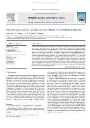
<strong>Bond<strong>in</strong>g</strong> <strong>Mechanisms</strong> <strong>in</strong> <strong>Resistance</strong> Microweld<strong>in</strong>g<br />
<strong>of</strong> <strong>316</strong> <strong>Low</strong>-Carbon Vacuum Melted Sta<strong>in</strong>less Steel Wires<br />
M.I. KHAN, J.M. KIM, M.L. KUNTZ, and Y. ZHOU<br />
<strong>Resistance</strong> microweld<strong>in</strong>g (RMW) is an important jo<strong>in</strong><strong>in</strong>g process used <strong>in</strong> the fabrication <strong>of</strong><br />
m<strong>in</strong>iature <strong>in</strong>struments, such as electrical and medical devices. The excellent corrosion resistance<br />
<strong>of</strong> <strong>316</strong> low-carbon vacuum melted (LVM) sta<strong>in</strong>less steel (SS) wire makes it ideal for biomedical<br />
applications. The current study exam<strong>in</strong>es the microstructure and mechanical properties <strong>of</strong><br />
crossed resistance microwelded <strong>316</strong>LVM wire. Microtensile and microhardness test<strong>in</strong>g was used<br />
to analyze the mechanical performance <strong>of</strong> welds, and fracture surfaces were exam<strong>in</strong>ed us<strong>in</strong>g<br />
scann<strong>in</strong>g electron microscopy. F<strong>in</strong>ally, a bond<strong>in</strong>g mechanism is proposed based on optimum<br />
jo<strong>in</strong>t break<strong>in</strong>g force (JBF) us<strong>in</strong>g metallurgical observations <strong>of</strong> weld cross sections. Moreover,<br />
comparisons with RMWs <strong>of</strong> Ni, Au-plated Ni, and SUS304 SS wire are discussed.<br />
DOI: 10.1007/s11661-009-9780-x<br />
Ó The M<strong>in</strong>erals, Metals & Materials Society and ASM International 2009<br />
I. INTRODUCTION<br />
EXCELLENT corrosion resistance coupled with<br />
nonmagnetic properties has made austenitic sta<strong>in</strong>less<br />
steel (SS) ideal for implantable medical devices. [1] In<br />
particular, <strong>316</strong> low-carbon vacuum melted (LVM) wire<br />
has been used <strong>in</strong> medical <strong>in</strong>struments for several<br />
decades. Various weld<strong>in</strong>g processes [2,3] have been used<br />
to fabricate these components; however, limited literature<br />
exists on microweld<strong>in</strong>g <strong>of</strong> austenitic SS used <strong>in</strong><br />
medical devices. [1,4]<br />
<strong>Resistance</strong> weld<strong>in</strong>g has been widely used <strong>in</strong> the<br />
electrical and medical <strong>in</strong>dustries, because it is an<br />
economical process that <strong>of</strong>fers improved productivity<br />
and equipment costs compared to laser weld<strong>in</strong>g. Medical<br />
devices are m<strong>in</strong>iature and <strong>in</strong>tegrated, which results<br />
<strong>in</strong> a reduction <strong>of</strong> scale <strong>in</strong> jo<strong>in</strong>t size from millimeters<br />
(mm) to micrometers (lm) <strong>in</strong> such applications <strong>in</strong>clud<strong>in</strong>g,<br />
but not limited to, biosensors, stents, catheters,<br />
pacemakers, and surgical <strong>in</strong>struments. [5] M<strong>in</strong>iature resistance<br />
weld<strong>in</strong>g is commonly known as small-scale resistance<br />
spot weld<strong>in</strong>g and is <strong>of</strong>ten referred to as resistance<br />
microweld<strong>in</strong>g (RMW).<br />
The RMW <strong>of</strong> Ni sheet, Ni wire, and Au-plated Ni<br />
wire has previously been <strong>in</strong>vestigated. [6–8] Fukumoto<br />
et al. [7] described the weld development and bond<strong>in</strong>g<br />
mechanism for pure Ni wire by <strong>in</strong>crementally <strong>in</strong>creas<strong>in</strong>g<br />
the weld current. Solid-state bond<strong>in</strong>g produced the<br />
optimum jo<strong>in</strong>t break<strong>in</strong>g force (JBF). In the case <strong>of</strong> Auplated<br />
Ni wire, the optimized bond<strong>in</strong>g mechanism <strong>of</strong><br />
RMW was a comb<strong>in</strong>ation <strong>of</strong> solid-state bond<strong>in</strong>g,<br />
braz<strong>in</strong>g, and fusion weld<strong>in</strong>g. [8]<br />
M.I. KHAN and J.M. KIM, Students, M.L. KUNTZ, Research<br />
Assistant, and Y. ZHOU, Pr<strong>of</strong>essor, are with the Department <strong>of</strong><br />
Mechanical & Mechatronics Eng<strong>in</strong>eer<strong>in</strong>g, Centre for Advanced<br />
Materials Jo<strong>in</strong><strong>in</strong>g, University <strong>of</strong> Waterloo, Waterloo, ON, Canada<br />
N2L 3G1. Contact e-mail: ibraheem@rogers.com<br />
Manuscript submitted March 7, 2008.<br />
Article published onl<strong>in</strong>e February 20, 2009<br />
Recently, Fukumoto et al. [1] <strong>in</strong>vestigated RMW <strong>of</strong><br />
SUS304 SS wire, which is an austenitic SS. Solid-state<br />
bond<strong>in</strong>g was aga<strong>in</strong> suggested over fusion weld<strong>in</strong>g at the<br />
optimum JBF. However, the RMW bond<strong>in</strong>g mechanism<br />
<strong>of</strong> <strong>316</strong> LVM SS is not fully understood. The objective <strong>of</strong><br />
this study is to detail the bond<strong>in</strong>g mechanism <strong>of</strong><br />
<strong>316</strong>LVM SS through experimental development and to<br />
compare the jo<strong>in</strong>t formation and mechanical properties<br />
with previous studies on RMW <strong>of</strong> crossed wires.<br />
II. EXPERIMENTAL PROCEDURES<br />
A. Mach<strong>in</strong>e Setup and Weld<strong>in</strong>g Parameters<br />
The chemical composition for the 0.015-<strong>in</strong>.- (0.38-<br />
mm-) diameter <strong>316</strong> LVM SS wire (New England<br />
Precision Gr<strong>in</strong>d<strong>in</strong>g, Inc., Holliston, MA) is shown <strong>in</strong><br />
Table I. Before bond<strong>in</strong>g, all samples were ultrasonically<br />
cleaned <strong>in</strong> acetone. Figure 1(a) shows a schematic <strong>of</strong> the<br />
wire dimensions and jo<strong>in</strong>t configuration, <strong>in</strong> which wires<br />
were bonded at right angles (90 deg). A MacGregor<br />
DC400P direct-current controller and Unitek 80A/115 V<br />
weld head (Miyachi Unitek Corporation, Monrovia, CA)<br />
were used. Flat-ended, round RWMA class 2 (Cu-Cr)<br />
electrodes with a 3.2-mm face diameter were used to<br />
apply force and current. Two electrode force levels were<br />
used, <strong>in</strong>clud<strong>in</strong>g 1.5 and 5 kg-f. The current was varied<br />
between 90 and 350 A and applied for a total weld time <strong>of</strong><br />
50 ms <strong>in</strong>clud<strong>in</strong>g an up-slope time <strong>of</strong> 10 ms and a downslope<br />
time <strong>of</strong> 3 ms.<br />
B. Microstructure and Mechanical Properties<br />
The JBF was determ<strong>in</strong>ed us<strong>in</strong>g an Instron model 5548<br />
microtensile tester (Instron, Norwood, MA). A 500 N<br />
load cell with an accuracy <strong>of</strong> ±0.4 pct was used with a<br />
crosshead speed <strong>of</strong> 10 mm/m<strong>in</strong>. Weld cross sections<br />
were observed us<strong>in</strong>g optical microscopy, and scann<strong>in</strong>g<br />
electron microscopy was used to exam<strong>in</strong>e fracture<br />
910—VOLUME 40A, APRIL 2009<br />
METALLURGICAL AND MATERIALS TRANSACTIONS A
Table I.<br />
Chemical Composition <strong>of</strong> <strong>316</strong>LVM Wire<br />
C Mn Si P S Cr Ni Mo Cu N Fe<br />
Wt pct 0.024 1.84 0.75 0.017
observed <strong>in</strong> Figures 2(d) and (e), respectively. The high<br />
contact resistance resultant from low bond<strong>in</strong>g force<br />
(1.5 kg-f) coupled with high electrical resistivity<br />
(740 lX mm) <strong>of</strong> the <strong>316</strong> LVM SS enabled peak temperatures<br />
to surpass the liquidus and form a dendritic<br />
solidification structure after rapid cool<strong>in</strong>g. Given the<br />
chemical composition <strong>of</strong> <strong>316</strong> LVM SS (Table I), the<br />
expected solidification mode would be either austenite<br />
(A) or austenite-ferrite (AF), which are common to<br />
similar grades <strong>of</strong> austenitic SS. [11] Figure 2(e) shows that<br />
the solidification mode was predom<strong>in</strong>antly austenitic<br />
(A).<br />
Increas<strong>in</strong>g the current to 225 A resulted <strong>in</strong> full fusion<br />
zone penetration and complete set-down, as shown <strong>in</strong><br />
Figure 2(f). The formation <strong>of</strong> the fusion zone, or the<br />
proposed ‘‘5th stage’’ <strong>of</strong> bond development, was<br />
observed <strong>in</strong> RMW <strong>of</strong> <strong>316</strong> LVM SS wires but absent <strong>in</strong><br />
Ni wires, likely due to the substantially higher electrical<br />
resistivity <strong>of</strong> <strong>316</strong> LVM SS. Overheat<strong>in</strong>g occurred when<br />
350 A was applied, such that severe expulsion and<br />
deformation created the unacceptable weld pr<strong>of</strong>ile<br />
shown <strong>in</strong> Figure 2(g).<br />
B. Relative Set-Down and JBF<br />
The effect <strong>of</strong> peak current on set-down is shown <strong>in</strong><br />
Figure 3. There was an <strong>in</strong>itial set-down <strong>of</strong> around<br />
20 pct, called cold collapse, due to the applied force <strong>of</strong><br />
1.5 kg-f. A gradual <strong>in</strong>crease <strong>in</strong> set-down, up to 40 pct,<br />
was observed as the current was <strong>in</strong>creased to 150 A.<br />
Above 150 A, the set-down suddenly <strong>in</strong>creased to<br />
90 pct, which was attributed to the collapse <strong>of</strong> the wires<br />
upon melt<strong>in</strong>g. Complete set-down was atta<strong>in</strong>ed with<br />
weld currents above 200 A, when full fusion occured.<br />
The JBF as a function <strong>of</strong> current and the correspond<strong>in</strong>g<br />
fracture modes are shown <strong>in</strong> Figure 4. A m<strong>in</strong>imum<br />
weld current <strong>of</strong> 90 A was required to <strong>in</strong>itiate bond<strong>in</strong>g. It<br />
is likely that a requisite for bond<strong>in</strong>g was the squeez<strong>in</strong>g<br />
out <strong>of</strong> surface contam<strong>in</strong>ants observed <strong>in</strong> Figure 2(b).<br />
There was a gradual <strong>in</strong>crease <strong>in</strong> JBF between 90 and<br />
200 A. The peak JBF <strong>of</strong> about 75 N was atta<strong>in</strong>ed when<br />
Fig. 2—Weld cross sections for RMW <strong>316</strong> LVM us<strong>in</strong>g 1.5 kg-f weld<br />
force.<br />
Fig. 3—Set-down as a function <strong>of</strong> RMW current for <strong>316</strong> LVM us<strong>in</strong>g<br />
1.5 kg-f weld force.<br />
912—VOLUME 40A, APRIL 2009<br />
METALLURGICAL AND MATERIALS TRANSACTIONS A
the current exceeded 200 A. Overweld<strong>in</strong>g occurred when<br />
the peak current surpassed 350 A. Metallographic<br />
observation <strong>of</strong> a weld cross section at the peak JBF<br />
Fig. 4—JBF as a function <strong>of</strong> current for RMW <strong>316</strong>LVM us<strong>in</strong>g<br />
1.5 kg-f weld force.<br />
current range (Figure 2(f)) showed full-fusion weld<strong>in</strong>g.<br />
Hence, the optimized bond<strong>in</strong>g mechanism for maximum<br />
JBF can be described as full penetration fusion weld<strong>in</strong>g,<br />
where the entire cross section <strong>of</strong> wire melts and<br />
resolidifies. The surface tension <strong>of</strong> the liquid and the<br />
presence <strong>of</strong> the electrodes kept the liquid with<strong>in</strong> the jo<strong>in</strong>t<br />
compared to the overweld<strong>in</strong>g condition, where the<br />
fusion zone became too large and was subject to dropthrough<br />
and th<strong>in</strong>n<strong>in</strong>g defects, which reduced the<br />
mechanical properties. Large variations <strong>in</strong> the JBF were<br />
observed for the optimal conditions, which has also been<br />
shown <strong>in</strong> past literature. [1,7,8] This scatter may be<br />
attributed to the nature <strong>of</strong> the tensile test setup, which<br />
<strong>in</strong>evitably resulted <strong>in</strong> comb<strong>in</strong>ed load<strong>in</strong>g conditions.<br />
C. Fracture Surfaces<br />
Fracture surfaces <strong>of</strong> tensile samples are shown <strong>in</strong><br />
Figures 5 through 7. Interfacial failure modes were<br />
observed for the 100 A weld<strong>in</strong>g condition (Figure 5). A<br />
small bonded region, about 150 lm <strong>in</strong> diameter, was<br />
evident at the center <strong>of</strong> the fracture surface. Dimples <strong>in</strong><br />
this region are similar to those observed by Wang<br />
Fig. 5—Fracture surfaces for weld made us<strong>in</strong>g 100 A and 1.5 kg-f weld force.<br />
Fig. 6—Fracture surfaces for weld made us<strong>in</strong>g 120 A and 1.5 kg-f weld force.<br />
METALLURGICAL AND MATERIALS TRANSACTIONS A VOLUME 40A, APRIL 2009—913
Fig. 7—Fracture surfaces show<strong>in</strong>g transition to HAZ failure us<strong>in</strong>g 1.5 kg-f weld force.<br />
et al. [13] for diffusion bond<strong>in</strong>g. The periphery was<br />
deformed by cold collapse, show<strong>in</strong>g an impr<strong>in</strong>t <strong>of</strong> the<br />
opposite wire. Interfacial fracture was once aga<strong>in</strong><br />
observed at 120 A, as shown <strong>in</strong> Figure 6. As compared<br />
to 100 A, the 120 A weld<strong>in</strong>g condition resulted <strong>in</strong> a<br />
larger bonded area, around 300 lm <strong>in</strong> diameter, which<br />
resulted <strong>in</strong> a higher JBF. Figure 6(b) shows the ductile<br />
dimpled fracture surface area <strong>in</strong> the center.<br />
Fracture surfaces for 150, 200, and 225 A weld<strong>in</strong>g<br />
conditions are shown <strong>in</strong> Figure 7. As previously discussed,<br />
above 120 A, transition to a predom<strong>in</strong>antly<br />
fusion bond<strong>in</strong>g mechanism occurred. Similarly, the<br />
914—VOLUME 40A, APRIL 2009<br />
METALLURGICAL AND MATERIALS TRANSACTIONS A
failure mode also showed a transition from <strong>in</strong>terfacial,<br />
to partial-<strong>in</strong>terfacial, and f<strong>in</strong>ally, to HAZ failure.<br />
Figure 7(a) (150 A) shows the beg<strong>in</strong>n<strong>in</strong>g <strong>of</strong> the transition<br />
toward partial <strong>in</strong>terfacial failure, where fracture<br />
occurred near the <strong>in</strong>terface. Figure 7(b) (200 A) shows a<br />
failure with a dimpled fracture surface, which occurred<br />
through the fusion zone and <strong>in</strong>dicated a more ductile<br />
failure. In Figure 7(c) (225 A), failure occurred <strong>in</strong> the<br />
HAZ, which had been s<strong>of</strong>tened by recrystallization. The<br />
highest JBF was observed with this ductile HAZ failure<br />
mode.<br />
D. Hardness<br />
Hardness traverses along the top, middle, and bottom<br />
portions <strong>of</strong> the longitud<strong>in</strong>al sections <strong>of</strong> the crosswire<br />
jo<strong>in</strong>ts are shown <strong>in</strong> Figure 8, for weld currents <strong>of</strong> 120,<br />
150, and 225 A. The base metal hardness was <strong>in</strong> the<br />
range <strong>of</strong> 480 to 500 Hv, due to the cold draw<strong>in</strong>g<br />
production process for f<strong>in</strong>e wires, which typically creates<br />
a f<strong>in</strong>e-gra<strong>in</strong>ed unidirectional structure. Toward the weld,<br />
<strong>in</strong> the HAZ, elevated peak temperatures dur<strong>in</strong>g the weld<br />
thermal cycle <strong>in</strong>duced recrystallization <strong>of</strong> the f<strong>in</strong>egra<strong>in</strong>ed<br />
base metal (BM), result<strong>in</strong>g <strong>in</strong> a s<strong>of</strong>tened region.<br />
The s<strong>of</strong>ten<strong>in</strong>g effect <strong>in</strong>creased approach<strong>in</strong>g the weld<br />
centerl<strong>in</strong>e, as the peak temperatures <strong>in</strong>creased as well.<br />
Other studies have shown similar s<strong>of</strong>ten<strong>in</strong>g <strong>in</strong> austenitic<br />
steels due to weld<strong>in</strong>g thermal cycles. [14,15]<br />
From Figure 8, it can be shown that the size <strong>of</strong> the<br />
s<strong>of</strong>tened region <strong>in</strong>creased with <strong>in</strong>creas<strong>in</strong>g current. Along<br />
with the s<strong>of</strong>tened region, the amount <strong>of</strong> set-down and<br />
HAZ depth also <strong>in</strong>creased. For the 120 A condition, the<br />
general trend was a gradual decrease <strong>in</strong> HAZ size from<br />
the top to bottom pr<strong>of</strong>ile, which corresponds with the<br />
expected peak temperature distribution. This result<br />
co<strong>in</strong>cides with the <strong>in</strong>terfacial failure mode, <strong>in</strong>dicat<strong>in</strong>g<br />
fracture followed the s<strong>of</strong>ter region near the wire<br />
<strong>in</strong>terface.<br />
The 150 and 225 A welds produced a predom<strong>in</strong>antly<br />
dendritic solidification structure near the fay<strong>in</strong>g surface.<br />
The m<strong>in</strong>imum hardness values for all welds were near<br />
200 Hv, and there was no apparent difference between<br />
the FZ and the HAZ. This was expected s<strong>in</strong>ce there was<br />
a loss <strong>of</strong> the orig<strong>in</strong>al work harden<strong>in</strong>g due to recrystallization<br />
and resolidification <strong>of</strong> the austenitic microstructures<br />
<strong>in</strong> the HAZ and FZ, respectively. Furthermore, the<br />
enlarged s<strong>of</strong>tened regions <strong>of</strong> the higher current welds<br />
compared to the 120 A weld expla<strong>in</strong> the transition from<br />
<strong>in</strong>terfacial to partial <strong>in</strong>terfacial failure mode.<br />
A schematic depict<strong>in</strong>g the fracture mode transition<br />
from <strong>in</strong>terfacial to HAZ is shown <strong>in</strong> Figure 9. At lower<br />
currents, a weak bond <strong>in</strong>duced <strong>in</strong>terfacial failure.<br />
However, as the current <strong>in</strong>creased, there was competition<br />
between <strong>in</strong>terfacial and s<strong>of</strong>tened HAZ failure.<br />
Eventually, a transition occurred where fracture followed<br />
the s<strong>of</strong>tened HAZ/FZ region. F<strong>in</strong>ally, dur<strong>in</strong>g full<br />
set-down, fracture propagated through the s<strong>of</strong>t outer<br />
edge <strong>of</strong> the HAZ material <strong>in</strong> one <strong>of</strong> the wires.<br />
Fig. 8—Hardness trace along welded jo<strong>in</strong>t for welds made us<strong>in</strong>g 120<br />
A and 1.5 kg-f weld force.<br />
IV. DISCUSSION<br />
A. Mechanism <strong>of</strong> Jo<strong>in</strong>t Formation<br />
The mechanisms <strong>of</strong> jo<strong>in</strong>t formation <strong>of</strong> crossed RMW<br />
wire have been detailed by Fukumoto et al. for Ni,<br />
Au-plated Ni, and SUS304 SS. [5–7] Fukumoto and Zhou [5]<br />
showed a maximum JBF <strong>of</strong> around 70 N (~7 kg-f) for<br />
400-lm-diameter Ni wire at 450 A. In a later publication,<br />
Fukumoto et al. [6] reported similar strengths for<br />
400-lm Ni wire plated with 4-lm Au; however, a higher<br />
600 A current was required for bond<strong>in</strong>g. Recently,<br />
Fukumoto et al. [7] exam<strong>in</strong>ed 400-lm-diameter SUS304<br />
SS wire us<strong>in</strong>g an 8-ms weld time. It was determ<strong>in</strong>ed that<br />
a JBF <strong>of</strong> about 120 N could be atta<strong>in</strong>ed when employ<strong>in</strong>g<br />
a 6 kg-f weld<strong>in</strong>g force and 300 A current. Each <strong>of</strong> the<br />
aforementioned publications stated that the primary<br />
jo<strong>in</strong><strong>in</strong>g mechanism was solid-state bond<strong>in</strong>g. In contrast,<br />
the current study showed that the primary mechanism<br />
observed for <strong>316</strong> LVM SS crossed-wire weld<strong>in</strong>g was<br />
fusion weld<strong>in</strong>g.<br />
Figure 10 shows a schematic diagram detail<strong>in</strong>g the<br />
jo<strong>in</strong>t formation for <strong>316</strong> LVM SS. Dur<strong>in</strong>g weld<strong>in</strong>g, the<br />
1.5 kg-f weld<strong>in</strong>g force resulted <strong>in</strong> an <strong>in</strong>itial deformation<br />
and larger contact area (Figures 2(a) and 10(a)). As the<br />
weld<strong>in</strong>g current <strong>in</strong>creased to 90 A, surface material and<br />
METALLURGICAL AND MATERIALS TRANSACTIONS A VOLUME 40A, APRIL 2009—915
mechanical properties. Electrode stick<strong>in</strong>g, however, was<br />
not observed at the current levels tested.<br />
The differences <strong>in</strong> bond<strong>in</strong>g mechanism compared to<br />
past literature may be attributed to several factors,<br />
<strong>in</strong>clud<strong>in</strong>g weld<strong>in</strong>g force, current, and material properties.<br />
For example, the lower electrical resistivity <strong>of</strong> Ni<br />
(69.3 lX mm) compared to <strong>316</strong>LVM SS (740 lX mm)<br />
resulted <strong>in</strong> lower peak temperatures <strong>in</strong> Ni dur<strong>in</strong>g<br />
RMW. [16,17] The higher peak temperatures for SS were<br />
more likely to surpass the liquidus temperature and<br />
form a fusion zone. However, SUS304 SS also produced<br />
a predom<strong>in</strong>ately solid-state bond, and it has similar<br />
electrical resistivity (720 lX mm) to the <strong>316</strong> LVM SS.<br />
This was likely due to the higher electrode force used to<br />
weld SUS304 SS, 6 kg-f for SUS304, compared to<br />
1.5 kg-f, which resulted <strong>in</strong> a lower current density,<br />
contact resistance, and peak temperatures.<br />
Fig. 9—Schematic <strong>of</strong> failure modes transition<strong>in</strong>g from <strong>in</strong>terfacial to<br />
HAZ.<br />
contam<strong>in</strong>ants were melted and expelled from the <strong>in</strong>terface.<br />
This expulsion aided <strong>in</strong> clean<strong>in</strong>g the <strong>in</strong>terface by<br />
squeez<strong>in</strong>g out contam<strong>in</strong>ants (Figures 2(b), 2(c), 10(b),<br />
and 10(c)). Further <strong>in</strong>crease <strong>in</strong> current resulted <strong>in</strong> a<br />
recrystallized HAZ and formation <strong>of</strong> a solid-state bond<br />
(Figures 2(d) and 10(d)). The recrystallized HAZ exhibited<br />
a lower hardness (200 Hv) compared to the f<strong>in</strong>egra<strong>in</strong>ed<br />
base metal (500 Hv) microstructure. Dur<strong>in</strong>g<br />
RMW <strong>of</strong> Ni wire, Fukomoto et al. observed both<br />
surface melt<strong>in</strong>g and recrystallization stages. [6]<br />
As currents <strong>in</strong>creased to 120 A, peak temperatures at<br />
the weld <strong>in</strong>terface surpassed the liquidus temperature<br />
and generated a fusion zone (Figures 2(e) and 10(e)).<br />
The fusion zone was characterized by a columnar<br />
dendritic solidification structure surrounded by a recrystallized<br />
HAZ. At higher currents, the fusion zone<br />
growth was coupled with <strong>in</strong>creased set-down and<br />
expulsion (Figures 2(f) and 10(f)). Full set-down was<br />
observed at 225 A with a predom<strong>in</strong>ately fusion-welded<br />
jo<strong>in</strong>t hav<strong>in</strong>g a columnar dendritic structure (Figures 2(g)<br />
and 8(g)). F<strong>in</strong>ally, overweld<strong>in</strong>g occured when currents<br />
reached 350 A. Excessive heat<strong>in</strong>g caused severe<br />
expulsion and deformation, which adversely affected<br />
B. Transition <strong>in</strong> Mechanism <strong>of</strong> Jo<strong>in</strong>t Formation<br />
Experimental verification was conducted to characterize<br />
the transition from solid-state bond<strong>in</strong>g to fusion<br />
weld<strong>in</strong>g. The JBF as a function <strong>of</strong> current for 1.5 and<br />
5 kg-f and the correspond<strong>in</strong>g transition <strong>in</strong> mechanism <strong>of</strong><br />
jo<strong>in</strong>t formation are shown <strong>in</strong> Figure 11. It can be shown<br />
that similar JBF values were atta<strong>in</strong>ed for both weld<strong>in</strong>g<br />
conditions; however, the range over which solid-state<br />
bond<strong>in</strong>g is prevalent was <strong>in</strong>creased by us<strong>in</strong>g a higher<br />
electrode force. Figure 12 shows the weld cross section<br />
for the 300 and 400 A conditions. Fusion occurred<br />
when currents reached 400 A, which was higher than the<br />
120 A observed for the 1.5 kg-f weld<strong>in</strong>g force. Figure 13<br />
shows similar HAZ fracture modes for the predom<strong>in</strong>ately<br />
solid-state 5 kg-f weld<strong>in</strong>g force, which was also<br />
observed for the 1.5 kg-f condition.<br />
A schematic show<strong>in</strong>g the transition <strong>in</strong> mechanism <strong>of</strong><br />
jo<strong>in</strong>t formation is shown <strong>in</strong> Figure 14. Differences <strong>in</strong><br />
solid-state and fusion weld<strong>in</strong>g mechanisms are largely<br />
dependent on the peak temperatures and, hence, heat<br />
generation. <strong>Low</strong>er force coupled with materials with<br />
high resistivity will tend toward fusion weld<strong>in</strong>g as<br />
compared to solid state, which requires higher force<br />
and lower material resistivity. It is well known that the<br />
approximate heat generated dur<strong>in</strong>g RMW is constituted<br />
by the follow<strong>in</strong>g equation:<br />
Q ¼ I 2 Rt<br />
where the current (I) and time (t) are controlled<br />
variables. The term R is the resistance, and <strong>in</strong> RMW,<br />
it is dependent on weld<strong>in</strong>g force and a comb<strong>in</strong>ation <strong>of</strong><br />
bulk resistivity and contact resistivity to give the overall<br />
material resistivity. Bulk resistance is a material property,<br />
while contact resistance generally decreases with<br />
<strong>in</strong>creas<strong>in</strong>g weld force. Referr<strong>in</strong>g to Figure 14, it can be<br />
shown that <strong>in</strong>creas<strong>in</strong>g weld<strong>in</strong>g force and lower<strong>in</strong>g the<br />
overall resistivity generally tends toward decreased<br />
<strong>in</strong>terfacial heat generation, which is ideal for solid-state<br />
bond<strong>in</strong>g (shifts the transition toward higher currents).<br />
In contrast, lower weld<strong>in</strong>g force coupled with higher<br />
material resistivity creates a propensity toward fusion<br />
weld<strong>in</strong>g (shifts the transition toward lower currents).<br />
½2Š<br />
916—VOLUME 40A, APRIL 2009<br />
METALLURGICAL AND MATERIALS TRANSACTIONS A
Fig. 10—Schematic <strong>of</strong> proposed RMW bond<strong>in</strong>g mechanism <strong>of</strong> crossed <strong>316</strong> LVM SS wire.<br />
Therefore, depend<strong>in</strong>g on the specific bond<strong>in</strong>g condition<br />
and material properties, the resultant bond<strong>in</strong>g mechanisms<br />
could be either solid state or fusion weld<strong>in</strong>g.<br />
The JBF <strong>of</strong> the solid-state-bonded SUS304 SS was<br />
reported to be slightly higher than the <strong>316</strong> LVM <strong>in</strong> the<br />
current study. Discrepancies may be attributed to a<br />
comb<strong>in</strong>ation <strong>of</strong> differences <strong>in</strong> wire diameter and base<br />
material tensile strength. Base metal strengths for the<br />
SUS304 SS are typically higher than the <strong>316</strong>LVM SS;<br />
however, the <strong>316</strong> LVM SS has superior resistance to<br />
corrosion. In medical applications, such as stents,<br />
smooth surfaces are also critical <strong>in</strong> avoid<strong>in</strong>g damage to<br />
the epithelial surface. Figure 15 shows the surfaces <strong>of</strong><br />
the optimized JBF bond<strong>in</strong>g condition for 304 and <strong>316</strong><br />
LVM SS welded at fusion weld<strong>in</strong>g and solid-state<br />
bond<strong>in</strong>g conditions, respectively. A smoother weld<br />
surface is observed for the fusion-welded <strong>316</strong> LVM<br />
compared to both solid-state welded <strong>316</strong> LVM and<br />
SUS304 SS, which exhibits rough flash material along<br />
the wire perimeter. This shows that the fusion-welded SS<br />
produced a smoother surface then the comparable jo<strong>in</strong>t<br />
us<strong>in</strong>g a solid-state bond<strong>in</strong>g mechanism.<br />
METALLURGICAL AND MATERIALS TRANSACTIONS A VOLUME 40A, APRIL 2009—917
Fig. 11—JBF as a function <strong>of</strong> current for RMW <strong>316</strong> LVM.<br />
Fig. 14—Schematic show<strong>in</strong>g transition <strong>in</strong> mechanism <strong>of</strong> jo<strong>in</strong>t formation.<br />
Fig. 12—Weld cross section for RMW made us<strong>in</strong>g 5 kg-f weld<strong>in</strong>g force.<br />
Fig. 13—Representative fracture surfaces for tensile test <strong>of</strong> 400 A and 5 kg-f weld.<br />
918—VOLUME 40A, APRIL 2009<br />
METALLURGICAL AND MATERIALS TRANSACTIONS A
mechanism was detailed and compared to Ni, Au-plated<br />
Ni, and SUS304 SS. In addition, the transition <strong>in</strong> the<br />
mechanism <strong>of</strong> jo<strong>in</strong>t formation was detailed. Key conclusions<br />
formed from the results and discussions are<br />
presented as follows.<br />
1. The proposed bond<strong>in</strong>g process is (1) cold collapse,<br />
(2) surface melt<strong>in</strong>g and squeeze-out, (3) recrystallization<br />
and liquation, (4) fusion weld<strong>in</strong>g, and (5)<br />
overweld<strong>in</strong>g.<br />
2. Solid-state bond<strong>in</strong>g transitioned to fusion weld<strong>in</strong>g,<br />
and the tendency for fusion weld<strong>in</strong>g was promoted<br />
with both <strong>in</strong>creased material resistivity and lowered<br />
weld<strong>in</strong>g force. Fusion weld<strong>in</strong>g stages <strong>in</strong>clude (a) <strong>in</strong>itial<br />
fusion weld<strong>in</strong>g, (b) fusion zone growth and setdown,<br />
and (c) full set-down, sequentially.<br />
3. Fracture modes <strong>in</strong> tensile test<strong>in</strong>g progressed with<br />
<strong>in</strong>creas<strong>in</strong>g current from <strong>in</strong>terfacial failure to fusion<br />
zone failure and, f<strong>in</strong>ally, to HAZ failure.<br />
4. The JBF and set-down <strong>in</strong>creased with <strong>in</strong>creas<strong>in</strong>g<br />
weld current, reach<strong>in</strong>g a maximum JBF <strong>of</strong> 8 kg-f<br />
with 100 pct set-down.<br />
5. Fusion weld<strong>in</strong>g at low bond<strong>in</strong>g force (1.5 kg-f) resulted<br />
<strong>in</strong> sound jo<strong>in</strong>ts with smooth surfaces and<br />
high JBF.<br />
Fig. 15—Surface <strong>of</strong> the optimized bond<strong>in</strong>g condition for austenitic<br />
SS.<br />
V. CONCLUSIONS<br />
The present study has exam<strong>in</strong>ed RMW <strong>of</strong> crossed <strong>316</strong><br />
LVM SS wire by observ<strong>in</strong>g microstructure, mechanical<br />
properties, and fracture surfaces. The bond<strong>in</strong>g<br />
REFERENCES<br />
1. S. Fukumoto, T. Matsuo, H. Tsubak<strong>in</strong>o, and A. Yamamoto:<br />
Mater. Trans., 2007, vol. 48 (4), pp. 813–20.<br />
2. R. S<strong>in</strong>gh and N.B. Dahotre: J. Mater. Sci., 2005, vol. 40 (21),<br />
pp. 5619–26.<br />
3. D.R. Haynes, T.N. Crotti, and M.R. Haywood: J. Biomed. Mater.<br />
Res., 2000, vol. 49 (2), pp. 167–75.<br />
4. I. Khan and Y. Zhou: Proc. <strong>in</strong> Materials and Processes for Medical<br />
Devices Conf. (MPMD), Palm Spr<strong>in</strong>gs, CA, Sept. 2007.<br />
5. K.J. Ely and Y. Zhou: Sci. Technol. Weld. Jo<strong>in</strong>., 2001, vol. 6 (2),<br />
pp. 63–72.<br />
6. W. Tan, Y. Zhou, and H.W. Kerr: Metall. Mater. Trans. A, 2002,<br />
vol. 33A, pp. 2667–76.<br />
7. S. Fukumoto and Y. Zhou: Metall. Mater. Trans. A, 2004,<br />
vol. 35A, pp. <strong>316</strong>5–76.<br />
8. S. Fukumoto, Z. Chen, and Y. Zhou: Metall. Mater. Trans. A,<br />
2005, vol. 36A, pp. 2717–24.<br />
9. V.E. Ataush, E.G. Moskv<strong>in</strong>, and V.P. Leonov: Weld. Int., 1992,<br />
vol. 6 (8), pp. 624–27.<br />
10. C.D. Lund<strong>in</strong>, C.Y.P. Qiao, and Y. Kikuchi: Heat-Resistant<br />
Materials, Proc. 1st Int. Conf., ASM International, Fontana, WI,<br />
1991, pp. 71–79.<br />
11. J.C. Lippold and D.J. Kotecki: Weld<strong>in</strong>g Metallurgy and Weldability<br />
<strong>of</strong> the Sta<strong>in</strong>less Steels, John Wiley & Sons, Inc., Toronto,<br />
ON, Canada, 2005, pp. 153 and 155.<br />
12. V.P. Kujanpaa, S.A. David, and C.L. White: Weld. J., 1987,<br />
vol. 66 (8), pp. 221–28.<br />
13. A. Wang, O. Ohashi, N. Yamaguchi, M. Aoki, Y. Higashi, and<br />
N. Hitomi: Nucl. Instrum. Meth. Phys. Res., Sec. B: Beam Interact.<br />
Mater. Atoms, 2003, vol. 206, pp. 219–23.<br />
14. K. Tsuchiya, H. Kawamura, and G. Kal<strong>in</strong><strong>in</strong>: J. Nucl. Mater.,<br />
2000, vol. 283 (287), pp. 1210–14.<br />
15. B. Gulenc, K. Develi, N. Kahraman, and A. Durgutlu: Int. J.<br />
Hydrogen Energy, 2005, vol. 30, pp. 1475–81.<br />
16. http://www.allmeasures.com/Formulae/static/materials/24/electrical_<br />
resistivity.htm.<br />
17. http://www.lenntech.com/Sta<strong>in</strong>less-steel-<strong>316</strong>L.htm.<br />
METALLURGICAL AND MATERIALS TRANSACTIONS A VOLUME 40A, APRIL 2009—919