Nikon FTn meter adjustment and cleaning procedure
Nikon FTn meter adjustment and cleaning procedure
Nikon FTn meter adjustment and cleaning procedure
- No tags were found...

You also want an ePaper? Increase the reach of your titles
YUMPU automatically turns print PDFs into web optimized ePapers that Google loves.
<strong>Nikon</strong> <strong>FTn</strong> <strong>meter</strong> <strong>adjustment</strong> <strong>and</strong> <strong>cleaning</strong> <strong>procedure</strong><br />
About this document:<br />
This document was prepared by a camera repair hobbyist as an aid to other camera repair<br />
hobbyists. It was prepared without any information from <strong>Nikon</strong>, Inc., <strong>and</strong> is provided without<br />
any guarantee as to completeness or accuracy.<br />
How the <strong>Nikon</strong> <strong>FTn</strong> light<strong>meter</strong> works:<br />
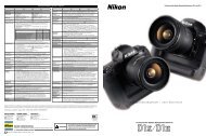
Refer to the schematic below. In both test <strong>and</strong> <strong>meter</strong> modes, the circuit is a voltage divider. The<br />
<strong>meter</strong> movement is centered when it has 0.025 volts across it. When the test button is pressed,<br />
current flows from battery negative, through test adjust trimpot, through the switch (green to<br />
white, pushbutton down), through the <strong>meter</strong> adjust trimpot, <strong>and</strong> then through the <strong>meter</strong> to case<br />
ground to battery positive.<br />
With a 2.7 volt battery this results in a current of about 16 micro-amps ((2.7 - .025)/(160,000 +<br />
6800)). This means the <strong>meter</strong> movement is about 1560 ohms (.025/.000016), <strong>and</strong> that the voltage<br />
at the switch is about .134 volts (.000016*(6800+1560)).<br />
Note that .025 volts at 16 micro-amps is much less than what an ohm<strong>meter</strong> will put out. Be<br />
careful not to put an ohm<strong>meter</strong> across the <strong>meter</strong> even indirectly. All potentio<strong>meter</strong>s <strong>and</strong> the<br />
resistor can safely be checked with an ohm<strong>meter</strong> if you test with the battery removed <strong>and</strong> the<br />
switch off, <strong>and</strong> read directly across a single potentio<strong>meter</strong>. The best way to check the <strong>meter</strong> for<br />
continuity is to check voltage from the <strong>meter</strong> lead to ground with the battery installed <strong>and</strong> the<br />
<strong>meter</strong> switch in the battery test position. If the <strong>meter</strong> is open, full battery voltage will be imposed<br />
on the <strong>meter</strong> with no <strong>meter</strong> movement.<br />
In <strong>meter</strong> mode, with the pushbutton up, the switch yellow, red, <strong>and</strong> white leads connected, the<br />
voltage divider is the two CdS photocells (60% center <strong>and</strong> 40% full frame) <strong>and</strong> the fixed 41 ohm<br />
resistor, against the main potentio<strong>meter</strong> <strong>and</strong> the <strong>meter</strong> (with trimpot) in parallel. The <strong>meter</strong> is<br />
centered when there is a voltage of .134 volts at the switch.<br />
The aperture lever, which moves the wiper, <strong>and</strong> the shutter speed & ASA setting, which turns the<br />
potentio<strong>meter</strong> resistive element, operate the main potentio<strong>meter</strong>. At somewhere around f/2, 1 sec,<br />
ASA 100 it is approx. 370K (maximum), <strong>and</strong> at around f/16, 1/1000 sec, ASA 40 it is approx.<br />
0.2 ohms (minimum). I'm not sure I got those settings exactly right (with the <strong>meter</strong> off the<br />
camera), but you should be able to see the ends of the potentio<strong>meter</strong> element easily, <strong>and</strong> check<br />
for maximum <strong>and</strong> minimum resistance at the crossover.<br />
There are no stops, the potentio<strong>meter</strong> will wrap around from max to min at long exposures <strong>and</strong><br />
wide apertures, causing the <strong>meter</strong> to stop functioning (needle will drop to off position).<br />
The photocell resistance (both cells) varies from over 4 Meg in a fairly dark room to less than<br />
200 ohms when the <strong>meter</strong> is held about 6 inches from a 60 watt bulb.
The above measurements are from a single working <strong>meter</strong>. Small variance can be expected from<br />
<strong>meter</strong> to <strong>meter</strong>.<br />
<strong>Nikon</strong> <strong>FTn</strong> Meter Schematic<br />
Troubleshooting:<br />
Check your batteries, they should be about 1.35 volts each.<br />
Meter completely dead - check the contacts of the battery holder first. The positive connection<br />
(tab on the side) becomes easily bent to where it will not make contact. With the battery cover<br />
off, press the batteries in <strong>and</strong> against the side contact with your finger, if the <strong>meter</strong> can be made<br />
to work this way (check with test button) then battery contact is the problem. Clean <strong>and</strong> slightly<br />
bend the contact, being careful not to bend it out too far so that it catches the cap <strong>and</strong> is pushed<br />
down too far.<br />
With the cover removed, verify about 2.7 volts between the battery negative terminal (center)<br />
<strong>and</strong> the ground strap (front, accessed through the round hole on the top left of <strong>meter</strong>).<br />
Test position makes <strong>meter</strong> needle move only about half way to center position - positive battery<br />
contact bent out too far, cap pushes it down too far connecting it to a single cell (shorting the<br />
other one out). Disassembly may be required to straighten the contact.<br />
Test function works but <strong>meter</strong> reads erratically or not at all - bad contact on main potentio<strong>meter</strong><br />
or poor connection; disassemble, inspect <strong>and</strong> clean.<br />
Adjustment (<strong>meter</strong> on camera):<br />
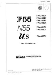
Peel off the leather <strong>meter</strong> cover <strong>and</strong> remove the 4 screws exposed. Remove the sheet metal<br />
cover. Two trim potentio<strong>meter</strong>s will be accessible, the front trim is for <strong>meter</strong> sensitivity <strong>and</strong> the
ear trim is for <strong>meter</strong> test. The sensitivity <strong>adjustment</strong> affects the <strong>meter</strong> test <strong>adjustment</strong>, but not<br />
vice versa, so adjust sensitivity first.<br />
Fig. 1 - <strong>FTn</strong> with cover removed<br />
Adjustment should preferably be done with fresh batteries.<br />
Focus the camera (full frame) on an evenly illuminated 18% gray card, <strong>and</strong> adjust the sensitivity<br />
to agree with a known accurate <strong>meter</strong>. If you don't have a known accurate <strong>meter</strong>, you can make<br />
an approximate setting by using a film manufacturers recommended setting for direct sunlight.<br />
For example, set the camera to ASA 100, 1/125 sec, f/16, <strong>and</strong> adjust the <strong>meter</strong> to center the<br />
needle when aimed at a gray card in direct sunlight. You could then make fine <strong>adjustment</strong>s based<br />
on test shots, for example, if tests indicate you need 1/2 stop more exposure, set up with the Grey<br />
card, center the needle, open up 1/2 stop, <strong>and</strong> re-center the <strong>meter</strong> using the sensitivity trim<br />
<strong>adjustment</strong>.<br />
After the sensitivity is adjusted, set the <strong>meter</strong> test trim so that the needle is centered when the test<br />
button is pressed.<br />
If <strong>meter</strong> cannot be adjusted, disassemble, clean <strong>and</strong> inspect.<br />
Disassembly:<br />
With <strong>meter</strong> removed from camera <strong>and</strong> sheet metal cover removed (see <strong>adjustment</strong> above):<br />
Remove batteries.
Remove front cover by removing 3 screws, pressing aperture lever inside cover slot, <strong>and</strong> pulling<br />
straight forward.<br />
Disconnect copper strap <strong>and</strong> 2 wires by loosening screws through round access hole on left side<br />
of <strong>meter</strong> (angled surface). Be sure to note which wire goes where.<br />
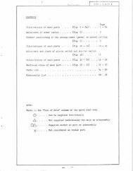
Remove 4 black screws from bottom of <strong>meter</strong>, 2 front screws directly under front latch pins<br />
(squeeze pincer lever for straight access) <strong>and</strong> 2 rear screws in corners next to eyepiece. Separate<br />
top <strong>and</strong> bottom halves carefully. Do not loose the 4 washers between the two halves, they should<br />
be glued on to the bottom half but sometimes fall off.<br />
Fig. 2 - <strong>FTn</strong> bottom view<br />
Cleaning:<br />
Inspect all connections <strong>and</strong> potentio<strong>meter</strong>s. Clean carefully with brush <strong>and</strong> gentle blower. Do not<br />
use any spray cleaner, especially on the bottom half, there is risk of getting cleaner <strong>and</strong> dirt on<br />
optical surfaces which are difficult to access. Tape head <strong>cleaning</strong> solution or alcohol <strong>and</strong> lintless<br />
swabs work well on potentio<strong>meter</strong> surfaces.<br />
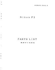
If the problem is a bad connection between the main potentio<strong>meter</strong> wiper <strong>and</strong> element, it will<br />
probably be necessary to remove the brass gear that the wiper is mounted on, <strong>and</strong> carefully clean<br />
the wiper. Mark the position of the gear before removing.
Fig. 3 - <strong>FTn</strong> top inside<br />
Fig. 4 - <strong>FTn</strong> bottom inside