Localization of Distributed Fiber Sensor Employing a Sub-Ring
Localization of Distributed Fiber Sensor Employing a Sub-Ring
Localization of Distributed Fiber Sensor Employing a Sub-Ring

Create successful ePaper yourself
Turn your PDF publications into a flip-book with our unique Google optimized e-Paper software.
is<br />
B<br />
LB<br />
0 B+LB 1 B<br />
LB<br />
is<br />
LB<br />
B<br />
0 B<br />
378<br />
JOURNAL OF ELECTRONIC SCIENCE AND TECHNOLOGY OF CHINA, VOL. 6, NO. 4, DECEMBER 2008<br />
n=0<br />
Using DC filter, the AC element <strong>of</strong> output is<br />
CW<br />
Coupler CCW<br />
ZB<br />
0 B=0<br />
1 ⎛<br />
2 ⎞<br />
Pn( τ ) = I0<br />
cos (<br />
n n) (<br />
n<br />
)<br />
n ⎜θτ + δ −θτ −δn<br />
− π⎟. (3)<br />
9× 2 ⎝ 3 ⎠<br />
CW<br />
CCW<br />
CW<br />
CCW<br />
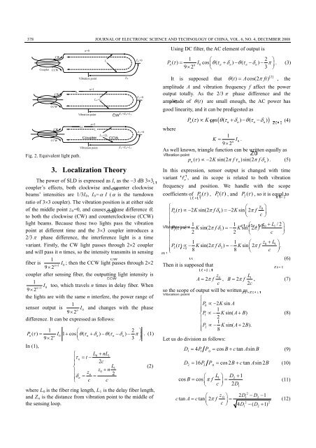
Fig. 2. Equivalent light path.<br />
L<br />
Vibration point<br />
n=1<br />
Vibration point<br />
2LB<br />
3. <strong>Localization</strong> Theory<br />
The power <strong>of</strong> SLD is expressed as I, as the −3P PdB 3×3<br />
coupler’s effects, both clockwise and counter clockwise<br />
beams’ intensities are 1/3IB0B, IB0B=α I (α is the turndown<br />
ratio <strong>of</strong> 3×3 coupler). The vibration position is at either side<br />
<strong>of</strong> the middle point zB0B=0, and causes a phase difference θBtB<br />
to both the clockwise (CW) and counterclockwise (CCW)<br />
light beams. Because those two lights pass the vibration<br />
point at different time and the 3×3 coupler introduces a<br />
2/3 π phase difference, the interference light is a time<br />
variant. Firstly, the CW light passes through 2×2 coupler<br />
and will pass it n times, so the intensity transmits in sensing<br />
1<br />
fiber is I<br />
1 0<br />
; then the CCW light passes through 2×2<br />
9 2 n +<br />
×<br />
coupler after sensing fiber, the outputting light intensity is<br />
1<br />
I<br />
1 0<br />
too, which travels n times in delay fiber. When<br />
9 2 n +<br />
×<br />
the lights are with the same n interfere, the power range <strong>of</strong><br />
1<br />
sensor output is<br />
0<br />
9 2 I and changes with the phase<br />
×<br />
n<br />
difference. It can be expressed as follows:<br />
1 2<br />
Pn( τ ) I0<br />
1 cos ⎛<br />
⎞<br />
= + θτ (<br />
n<br />
δn) θτ (<br />
n<br />
δ )<br />
n ⎜ + − −<br />
n<br />
− π⎟<br />
9× 2 ⎝ 3 ⎠ . (1)<br />
In (1),<br />
⎧ L0 + nL1<br />
τ<br />
n<br />
= t −<br />
⎪ 2c<br />
⎨<br />
L1<br />
(2)<br />
⎪ z<br />
z0<br />
+ n<br />
n<br />
δ<br />
2<br />
⎪ n<br />
= =<br />
⎩ c c<br />
where LB0 Bis the fiber ring length, LB1B the delay fiber length,<br />
and ZBnB the distance from vibration point to the middle <strong>of</strong><br />
the sensing loop.<br />
n=2<br />
Vibration point<br />
LB0 B+2LB<br />
Z<br />
ZB<br />
1 B=ZB 0 B+LB 1/<br />
B ZB2B=ZB0B+LB1 ZB<br />
1 B=0<br />
ZB<br />
2 B=0<br />
[2]<br />
It is supposed that θ() t = Acos(2 π ft)<br />
, the<br />
amplitude A and vibration frequency f affect the power<br />
output totally. As the 2/3 π phase difference and the<br />
amplitude <strong>of</strong> θ () t are small enough, the AC power has<br />
good linearity, and it can be predigested as<br />
where<br />
( )<br />
P() τ ∝ Kcos θτ ( + δ) −θτ ( − δ ) (4)<br />
n n n n n<br />
K<br />
1<br />
.<br />
= I0<br />
9 × 2 n<br />
n<br />
n<br />
As well known, triangle function can be written equally as<br />
p ( τ ) ∝ − 2Ksin(2 π fτ )sin(2 π fδ<br />
) . (5)<br />
n<br />
In this expression, sensor output is changed with time<br />
variant τ<br />
n<br />
, and its scope is related to both vibration<br />
frequency and position. We handle with the scope<br />
coefficients <strong>of</strong> P ( τ ) 0 , P () τ 1 , and P ( ) 2<br />
τ , so it is equal to<br />
⎧ ⎛ z0<br />
⎞<br />
⎪P0( τ) ∝− 2Ksin(2 π fδ0) =−2Ksin⎜2π<br />
f<br />
c<br />
⎟<br />
⎪<br />
⎝ ⎠<br />
⎪ 1 1 ⎛ z0 + L1/2⎞<br />
⎨P1( τ) ∝− Ksin(2 π fδ1) =− Ksin 2 f<br />
2 2<br />
⎜ π<br />
c<br />
⎟<br />
⎪<br />
⎝<br />
⎠<br />
⎪<br />
⎪ 1 1 ⎛ z0 + L1<br />
⎞<br />
P2() τ ∝− Ksin(2 π fδ2) =− Ksin 2 π f .<br />
⎪ 8 8<br />
⎜<br />
c<br />
⎟<br />
⎩<br />
⎝ ⎠<br />
(6)<br />
Then it is supposed that<br />
z0<br />
L1<br />
A = 2π<br />
f , B = 2π<br />
f , (7)<br />
c<br />
2c<br />
so the scope <strong>of</strong> output will be written as<br />
⎧<br />
⎪P0<br />
∝−2Ksin<br />
A<br />
⎪ 1<br />
⎨P1<br />
∝− Ksin( A+<br />
B)<br />
(8)<br />
⎪ 2<br />
⎪ 1<br />
P2<br />
∝− Ksin( A+<br />
2 B).<br />
⎪⎩ 8<br />
Let us do division as follows:<br />
D = 4P P = cos B+ ctan Asin<br />
B (9)<br />
1 1 0<br />
D = 16P P = cos 2B+ ctan Asin 2B<br />
(10)<br />
2 2 0<br />
⎛ L1 ⎞ D2<br />
+ 1<br />
cos B = cos⎜π<br />
f<br />
c<br />
⎟=<br />
⎝ ⎠ 2D<br />
2<br />
⎛ z<br />
0 ⎞ 2D1 −D2<br />
−1<br />
ctan A= ctan ⎜2π<br />
f<br />
c<br />
⎟=<br />
⎝ ⎠ 4 D − ( D + 1)<br />
1<br />
2 2<br />
1 2<br />
(11)<br />
(12)