FCC debutanizer revamp for flexibility and additional ... - Koch-Glitsch
FCC debutanizer revamp for flexibility and additional ... - Koch-Glitsch
FCC debutanizer revamp for flexibility and additional ... - Koch-Glitsch

You also want an ePaper? Increase the reach of your titles
YUMPU automatically turns print PDFs into web optimized ePapers that Google loves.
<strong>FCC</strong> Debutanizer Revamp <strong>for</strong> Flexibility <strong>and</strong><br />
Additional Capacity<br />
by<br />
Daryl W. Hanson, <strong>Koch</strong>-<strong>Glitsch</strong> Inc., Houston, Texas<br />
Todd Becker, CITGO Petroleum Corporation, Lake Charles, Louisiana<br />
Mike R. Resetarits, <strong>Koch</strong>-<strong>Glitsch</strong> Inc., Wichita, Kansas<br />
Presented at the Distillation Symposium<br />
2001 AIChE Spring National Meeting, Houston, Texas<br />
April 22-26, 2001<br />
UNPUBLISHED<br />
Copyright Daryl W. Hanson, Todd Becker, <strong>and</strong> Mike R. Resetarits<br />
The AIChE shall not be responsible <strong>for</strong> statements or opinions contained in its publications.
<strong>FCC</strong> DEBUTANIZER REVAMP FOR FLEXIBILITY AND ADDITIONAL CAPACITY<br />
Daryl W. Hanson<br />
<strong>Koch</strong>-<strong>Glitsch</strong>, Inc.<br />
12221 East Sam Houston Pkwy N<br />
Houston, TX 77044<br />
Phone: 713-427-7612<br />
Facsimile: 713-427-7613<br />
Todd Becker<br />
CITGO Petroleum Corporation (<strong>for</strong>merly with BP Americas – Toledo)<br />
P.O. Box 1562<br />
Lake Charles, LA 70602<br />
Phone: 337-708-0000<br />
Facsimile: 337-708-0000<br />
Mike R. Resetarits<br />
<strong>Koch</strong>-<strong>Glitsch</strong>, Inc.<br />
4111 E. 37 th Street North<br />
Wichita, KS 67208-0127<br />
Phone: 316-828-8220<br />
Facsimile: 316-828-7985<br />
i 4/20/01
<strong>FCC</strong> DEBUTANIZER REVAMP FOR FLEXIBILITY AND ADDITIONAL CAPACITY<br />
Introduction<br />
In the past few years, the refining <strong>and</strong> chemical industry (referred to as operators throughout the<br />
paper) have placed an emphasis on maximizing the value creation of each individual unit in the plant.<br />
This goal of maximum value creation has placed importance on the operators to maximize capacity of<br />
each unit to the major equipment bottleneck. The competitive marketplace has dictated that while<br />
operating at maximum capacities <strong>for</strong> the major equipment, the operators find ways to operate reliably<br />
<strong>for</strong> a four to six year run length or more.<br />
The two goals of maximum capacity <strong>and</strong> reliability have placed economic emphasis on the <strong>revamp</strong>s<br />
that occur during the unit shut-downs. Operating companies that select to <strong>revamp</strong> units are placing<br />
more responsibility <strong>and</strong> pressure on the equipment vendor to insure that the goals of the <strong>revamp</strong> are<br />
secured during post-<strong>revamp</strong> operation 1 . Many times, the goals <strong>for</strong> distillation units include:<br />
• Reliability.<br />
• Capacity.<br />
• Pressure Drop.<br />
• Efficiency.<br />
Since many of the goals above are intertwined, it is important that the operator realize the importance<br />
of the vendors experience when involved in the retrofit design.<br />
Operators have determined that it is more economically feasible to fix a problem with a solution that is<br />
100% correct, than to start-up <strong>and</strong> have a failure with a solution that is only 50% correct.<br />
Operators are finding that it is getting increasingly important to <strong>revamp</strong> towers with the least risky<br />
option. This is especially true <strong>for</strong> the “fixed equipment” in an operating facility. By fixed equipment,<br />
the authors are referring to equipment that can not be <strong>revamp</strong>ed or replaced on-line. The fixed<br />
equipment commonly causes the rest of the operating facility or other supporting units to be shutdown<br />
be<strong>for</strong>e a <strong>revamp</strong> can be initiated. Causing an operating facility or supporting unit shut-down is<br />
a large economic impact that all plants should avoid to be competitive.<br />
The authors wish to share a complete case study of a recent <strong>FCC</strong> Debutanizer <strong>revamp</strong>. We say<br />
complete because the original <strong>revamp</strong> of the distillation column was undertaken in 1995. In 1995, the<br />
tower was <strong>revamp</strong>ed from conventional trays to a “High Capacity” mini-valve tray 2 .<br />
After not meeting the capacity goals that the operator had intended, the tower had to be <strong>revamp</strong>ed a<br />
second time in early 1999 to achieve the original goals <strong>for</strong> the <strong>revamp</strong>. We will describe the complete<br />
1 of 20 4/20/01
<strong>FCC</strong> DEBUTANIZER REVAMP FOR FLEXIBILITY AND ADDITIONAL CAPACITY<br />
troubleshooting exercise, provide operating data & scans <strong>for</strong> the <strong>revamp</strong>s, <strong>and</strong> provide the economics<br />
that BP-Amoco realized.<br />
BP Amoco – Toledo Refinery<br />
BP-Amoco is a major worldwide operator of both refining <strong>and</strong> chemical plants. Their main production<br />
is concentrated in Petroleum Products, Ethylene, Propylene, Propane, Aviation Fuel, Jet, Kerosene,<br />
four grades of Gasoline Grades, Low <strong>and</strong> High Sulfur Diesel, Decanted Oil <strong>and</strong> Coke. The Toledo<br />
Refinery runs at a capacity of 150 MBPD of crude.<br />
The refinery layout includes two crude units, <strong>FCC</strong>, Isocracker, re<strong>for</strong>mers, cokers, <strong>and</strong> alkylation<br />
plants. BP-Amoco Toledo supplies products to the mid-west retail <strong>and</strong> chemical facilities. The <strong>FCC</strong><br />
unit generates one third of the refinery’s gasoline <strong>and</strong> 100% of the propylene production. There<strong>for</strong>e,<br />
as in any other refinery, it plays a key role in the economics <strong>for</strong> the refinery.<br />
<strong>FCC</strong> Liquids Recovery Unit<br />
With the spotlight in the refinery on the <strong>FCC</strong> Unit, operators are concerned with maximum <strong>FCC</strong> feed<br />
capacity, olefins recovery, <strong>and</strong> improved product qualities. In the <strong>FCC</strong> Unit, considering the main<br />
distillation columns, there are major driving <strong>for</strong>ces <strong>for</strong> <strong>revamp</strong>s. The <strong>FCC</strong> liquids recovery units place<br />
particular requirements on the distillation internals. Some of the distillation towers with their specific<br />
operating conditions are listed below:<br />
• Main Fractionator – Typically, tower operates at less than 35 PSIG in the spray regime <strong>for</strong> tray<br />
operation. Limitation is typically vapor flooding.<br />
• De-ethanizer Absorber / Stripper – Typically operates as 210 PSIG in the froth regime <strong>for</strong> tray<br />
operation. Limitation typically due to high liquid rates <strong>and</strong> downcomer backup issues.<br />
• Depropanizer / Debutanizer – Typically operates at 250 PSIG (De-C 3 ) <strong>and</strong> 150 PSIG (De-C 4 ).<br />
Limitation typically due to very high liquid rates <strong>and</strong> downcomer backup issues. These columns<br />
commonly have fouling problems <strong>for</strong> R<strong>FCC</strong> or ethylene units.<br />
• C3 Splitter (Propylene Splitter) – Column either operates at low pressure (150 PSIG) or high<br />
pressure (225 + PSIG). The operation is defined by L/V ratios close to one (1) <strong>and</strong> reflux ratios of<br />
9-15, depending on the number of theoretical stages, tray efficiency, <strong>and</strong> propylene recovery.<br />
Limitation is typically liquid h<strong>and</strong>ling <strong>and</strong> downcomer backup issues.<br />
Due to the varied operating conditions, concern has to be placed on the choice of distillation internal<br />
to achieve the required goals <strong>for</strong> the <strong>revamp</strong>. A solution that is tailor made <strong>for</strong> the <strong>FCC</strong>U MF 3,4 may<br />
not work <strong>for</strong> the high pressure light-ends fractionators 5 due to the different operating regimes <strong>and</strong><br />
unique internal loadings.<br />
2 of 14 4/20/01
<strong>FCC</strong> DEBUTANIZER REVAMP FOR FLEXIBILITY AND ADDITIONAL CAPACITY<br />
Proper application of a distillation product is crucial to achieve success. Improper application of<br />
distillation internals will promote projects that do not meet operating goals.<br />
BP-Amoco’s LRU<br />
The <strong>FCC</strong> gas plant <strong>for</strong> the BP-Amoco Toledo refinery is shown in the figure below.<br />
TO PRIMARY<br />
ABSORBER<br />
STRIPPER<br />
DEPROPANIZER I / II<br />
TO C3 SPLITTER /<br />
POLY GASOLINE<br />
FROM 2nd<br />
STAGE DRUM<br />
ALKYLATION<br />
FEED<br />
LIGHT CAT<br />
DISTILLATE<br />
DEBUTANIZER<br />
HEAVY CAT<br />
DISTILLATE<br />
Figure 1: <strong>FCC</strong> Liquids Recovery Unit<br />
BP-Amoco Toledo Refinery<br />
The liquids recovery unit (LRU) is typical of most major <strong>FCC</strong> units.<br />
The Deethanizer absorber / stripper system is operated in order to maximize C 3 recovery <strong>and</strong> C 2<br />
rejection. The bottoms of the stripper flows to the Debutanizer where <strong>FCC</strong> gasoline is stripped to an<br />
RVP limit. The overhead of the Debutanizer is sent to the downstream Depropanizer where the C 3 ’s<br />
are separated from the butanes. The overhead of the Depropanizer is sent to the P/P Splitter where<br />
propylene is produced <strong>for</strong> local consumption.<br />
For BP-Amoco, operating goals <strong>for</strong> the LRU are <strong>for</strong> maximum C 3 recovery, maximum gasoline<br />
recovery to a specified RVP, <strong>and</strong> <strong>for</strong> minimum C 5 breakthrough in the Debutanizer overhead. C 5<br />
breakthrough increases acid consumption in the downstream alkylation unit.<br />
3 of 14 4/20/01
<strong>FCC</strong> DEBUTANIZER REVAMP FOR FLEXIBILITY AND ADDITIONAL CAPACITY<br />
As previously mentioned, the Debutanizer provides the key separation between <strong>FCC</strong> Gasoline <strong>and</strong><br />
Butanes in the LRU. Some of the common variables are controlled from the Debutanizer:<br />
Table I: Key Debutanizer Operating Parameters<br />
Feed Temperature (°F) 235<br />
Overhead Pressure (PSIG) 130<br />
Overhead C5 (% mol) 0.5<br />
Debutanized Gasoline<br />
RVP (PSIG) 6.5<br />
Debutanizer Revamp #1 - 1995<br />
Prior to the 1995 <strong>revamp</strong>, the Debutanizer was identified as a bottleneck to achieve the anticipated<br />
capacity <strong>and</strong> product recovery of the <strong>FCC</strong> in the future. The LRU <strong>and</strong> treating sections were to be<br />
debottlenecked to allow <strong>for</strong> 93% C 3 recovery. Thus, the <strong>debutanizer</strong> was seen as a bottleneck at the<br />
design <strong>FCC</strong> feed rate, conversion, <strong>and</strong> proposed recovery.<br />
The Debutanizer contains 36 trays with the feed location between Tray #15/16 from the top (see<br />
Figure #2 <strong>for</strong> a schematic of the Debutanizer).<br />
Figure #2: <strong>FCC</strong> Debutanizer PFD<br />
1<br />
CWS<br />
FEED FROM<br />
e-C2 STRIPPER<br />
15<br />
16<br />
LPG<br />
36<br />
SLURRY P/A<br />
DEBUTANIZE<br />
GASOLINE<br />
4 of 14 4/20/01
<strong>FCC</strong> DEBUTANIZER REVAMP FOR FLEXIBILITY AND ADDITIONAL CAPACITY<br />
The Debutanizer overheads is water cooled prior to entering the flooded overhead drum. The reflux<br />
is flow controlled to the tower. The overhead product is controlled via flow <strong>and</strong> pressure control to two<br />
Depropanizers. The reboiler heat is supplied via hot slurry oil <strong>and</strong> is controlled based on an RVP<br />
analyzer / tray temperature combination.<br />
BP-Amoco initiated a study of the Debutanizer that confirmed the existing Debutanizer st<strong>and</strong>ard valve<br />
trays would be the limitation. Prior to the shut-down, BP-Amoco initiated the bid process to select the<br />
vendor to replace the distillation internals. BP-Amoco decided that to minimize the field work during<br />
the shut-down they would replace the trays with a high capacity mini-valve tray.<br />
During the 1995 shut-down, the trays were replaced <strong>and</strong> inspection completed to allow unit start-up<br />
late in 1995. After start-up, BP-Amoco noticed that the Debutanizer was limiting the throughput of the<br />
<strong>FCC</strong>U. For the Debutanizer, this was not an envious position to occupy. For the next six months,<br />
BP-Amoco concentrated on characterizing the tower’s per<strong>for</strong>mance to locate the bottlenecks to<br />
further capacity throughput.<br />
The Debutanizer operation was far from design or acceptable conditions. The design parameters <strong>and</strong><br />
Revamp #1 operating parameters are below in Table II.<br />
Table II: Operating Parameters: Design vs. Revamp #1<br />
Parameter Design Revamp #1 *<br />
Feed (BPD) 53,000 46,500<br />
Tower Pressure (PSIG) 140 138<br />
Tower DP (PSIG) 3.5 3.89<br />
Drum Temperature (°F) 70 66<br />
Top Temperature (°F) 150 148<br />
LPG (BPD) 18,600 12,550<br />
Reflux (BPD) 22,900 17,000<br />
Overhead C 5 (% mol) 0.5 3.22<br />
DeC4 Gasoline (BPD) 34,600 33,950<br />
Gasoline RVP (PSIG) 6.4 6.6<br />
Gasoline D-86, °F<br />
IBP 106 108<br />
10% 136 122<br />
30% 168 156<br />
* Operation prior to flood point (from 24 March 98). Tower flooded at reflux of 17,500 BPD.<br />
The summary <strong>for</strong> the Revamp #1 considers the maximum internal loadings that the trays could<br />
h<strong>and</strong>le prior to the flood point. Operations <strong>and</strong> engineering could flood the trays by watching the<br />
pressure drop through the tower. When the pressure drop reached 3.7-3.9 PSI, the tower would<br />
exhibit liquid back-up <strong>and</strong> proceed into a tail-spin flood.<br />
5 of 14 4/20/01
<strong>FCC</strong> DEBUTANIZER REVAMP FOR FLEXIBILITY AND ADDITIONAL CAPACITY<br />
The capacity deficit of the Revamp #1 was a large problem <strong>for</strong> the Debutanizer. Associated problems<br />
were the product purities <strong>for</strong> the Debutanizer. As a consequence of not meeting internal loadings,<br />
operations <strong>for</strong> the <strong>FCC</strong> were impacted:<br />
• Debutanized gasoline RVP was high <strong>and</strong> thus blending <strong>flexibility</strong> was lost <strong>for</strong> the refinery.<br />
Capacity in the stripping section limited the RVP to a low of 6.6 PSI.<br />
• C 5 content in the overhead was high due to the limitation in the rectification section. The<br />
reflux was limited to 17,000 BPD at high feed rates be<strong>for</strong>e tray flood. At this reflux, 3%<br />
mole C 5 ’s were left in the overhead. Sending C 5 ’s to the alkylation unit consumed acid,<br />
which was a large debit <strong>for</strong> the operations.<br />
Troubleshooting Revamp #1:<br />
Upon identification of the Debutanizer limitation, troubleshooters from B.P.-Amoco immediately began<br />
identifying possible reasons <strong>for</strong> the under-per<strong>for</strong>mance of the tower. Some are listed below, <strong>and</strong><br />
ruled out later:<br />
• Flow meter errors.<br />
• Damage to the trays.<br />
• Mis-installation of the trays.<br />
• Plugging of the internals with polymer material.<br />
As part of the troubleshooting, BP-Amoco utilized isotope scanning of the tower in order to rule<br />
out some of the above possibilities. Scanning has been used extensively in order to “look inside”<br />
the column to find the source or operating condition of the flood.<br />
Contrary to some beliefs 6 , the authors believe that the results from “advanced” scans can<br />
provide excellent in<strong>for</strong>mation to be used in the troubleshooting adventure. For example, in a high<br />
pressure gas plant, how would a person diagnosis a high liquid level in the bottoms boot section<br />
Level bridles in this service are known to be skewed by foaming. The temperature drops are<br />
small, the pressures are high so the liquid head measurements lack precise meaning, so<br />
scanning provides a basic <strong>and</strong> seemingly easy look inside the operating column if executed<br />
correctly.<br />
When a problem is evident, the troubleshooter should not <strong>for</strong>go any source of general<br />
in<strong>for</strong>mation. It is up to the troubleshooter to find out which pieces of in<strong>for</strong>mation are of primary<br />
importance, <strong>and</strong> which to consider as secondary importance.<br />
6 of 14 4/20/01
<strong>FCC</strong> DEBUTANIZER REVAMP FOR FLEXIBILITY AND ADDITIONAL CAPACITY<br />
Within the organization, the reasons listed above <strong>for</strong> flooding were routinely ruled out after<br />
<strong>additional</strong> scan <strong>and</strong> process data were becoming available. Shown in the figures attached are<br />
the scans that BP-Amoco executed <strong>for</strong> the stripping section <strong>and</strong> rectification section.<br />
Figure #3: Rectification Section Scan of<br />
Revamp #1 @ conditions listed in Table II<br />
Figure #4: Stripping Section Scan of<br />
Revamp #1 @ conditions listed in Table II<br />
The tower was scanned through the active areas of the tray. The scan identifies the flooded<br />
areas of the tower. When a tray is at or above incipient flood, the scan line <strong>for</strong> the active area<br />
starts to move away from the hatched area called “clear vapor space”. This indicates froth<br />
entrainment to the tray above <strong>and</strong> signifies that liquid is not obtaining disengagement from the upflowing<br />
vapor.<br />
The scan identifies that both the rectification <strong>and</strong> stripping section of the tower are operating at<br />
flooded conditions (liquid height on the tray decks is high), at lower than design rates. The<br />
Revamp #1 trays were operating at a small increment higher rates than the <strong>for</strong>mer sieve trays.<br />
7 of 14 4/20/01
<strong>FCC</strong> DEBUTANIZER REVAMP FOR FLEXIBILITY AND ADDITIONAL CAPACITY<br />
Tray Capacity – High Weir Loadings<br />
This tower, like many other high pressure columns, operated at considerable weir loadings. The<br />
weir loadings <strong>for</strong> this <strong>revamp</strong> approached 16 GPM/inch (192 GPM/ft) of weir in the stripping<br />
section of the tower. This is considered extreme liquid loadings by many distillation practitioners<br />
in the industry.<br />
The authors fear that the weir loading criteria is overstated as the primary indicator of liquid<br />
capacity of a distillation internal. The authors have several applications of towers that have been<br />
designed with liquid weir loadings over 20 GPM/inch.<br />
Several different possibilities <strong>for</strong> weir loading operation exist. Schematic of the Low Weir Loading<br />
vs. High Weir Loading is shown in the following figure.<br />
Figure x: Low vs. High Weir Loading<br />
Low Weir Loading Operation<br />
High Weir Loading Operation<br />
At high weir loadings, several phenomena occur:<br />
• Inlet “Liquid Rooster Tail” appears as described by Lockett.<br />
• The disengagement space becomes shorter due to increased froth height on the tray.<br />
• Liquid “jump” over outlet weir becomes high <strong>and</strong> downcomer inlet velocity is affected.<br />
• Liquid has difficulty in entering into downcomer mouth.<br />
All of these factors, if not considered in the tray design methodology, may cause per<strong>for</strong>mance<br />
shortfalls.<br />
8 of 14 4/20/01
<strong>FCC</strong> DEBUTANIZER REVAMP FOR FLEXIBILITY AND ADDITIONAL CAPACITY<br />
There are many liquid loading criteria that have can be extracted from public domain materials.<br />
One of the more prominent liquid loading criteria can be found in the Lockett 7 .<br />
Figure 5: Maximum Weir Loading vs. Tray Spacing (Lockett, 1986)<br />
20<br />
GPM/inch<br />
15<br />
10<br />
5<br />
0<br />
12 15 18 21 24<br />
Tray Spacing (inch)<br />
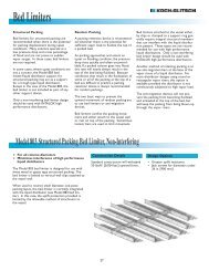
The above criteria are industry accepted guidelines. <strong>Koch</strong>-<strong>Glitsch</strong> has exceeded these high liquid<br />
guidelines by utilizing specialized tray features to limit froth height <strong>and</strong> promote liquid distribution to<br />
the active area. These applications have been made possible by testing Superfrac trays in the pilot<br />
plants at loadings up to 25 GPM/inch of weir.<br />
Analysis of Revamp #1 Shortfall<br />
BP-Amoco was concerned about the capacity of the Revamp #1 installed trays. There were still a<br />
few concerns that had to be rectified prior to finalizing the path <strong>for</strong>ward <strong>for</strong> the tower:<br />
1. Is the under-per<strong>for</strong>mance caused by tray damage <br />
2. Is the under-per<strong>for</strong>mance caused by plugging on the tray decks <br />
The first question above was addressed during the scan shown in Figure #3. If the tower had seen<br />
tray damage, this would be evident in the scan. A damaged tray can show several characteristics in<br />
a scan through the active area. Most of the time with a damaged tray, the scan at the tray elevation<br />
will show up with a sharp peak that falls as quickly as it ascends. This indicates no “froth” or liquid<br />
build-up / activity on the tray. All of the trays in the scan show liquid build-up, so there<strong>for</strong>e, damage<br />
was excluded from the list of possible causes.<br />
9 of 14 4/20/01
<strong>FCC</strong> DEBUTANIZER REVAMP FOR FLEXIBILITY AND ADDITIONAL CAPACITY<br />
The second question was an interesting question that could not be directly assessed from outside the<br />
column. Many <strong>FCC</strong> <strong>and</strong> Ethylene plant Debutanizers exhibit fouling due to polymerization. Typically,<br />
the fouling originates around the feed point, on the bottom few trays, <strong>and</strong> in the reboiler due to the<br />
high temperature at the bottom of the column. We believe that this polymer <strong>for</strong>mation can be<br />
attributed to vapor phase combination of olefins including butadienes <strong>and</strong> pentadienes.<br />
In the <strong>FCC</strong>U, Debutanizer fouling has been traced to the severity of cracking <strong>and</strong> the ° API of the oil<br />
being cracked. During previous shut-downs the Debutanizer was clean <strong>and</strong> showed no signs of<br />
fouling. But BP-Amoco was concerned that this may cause the current under-per<strong>for</strong>mance problems,<br />
so they investigated this possibility.<br />
Debutanizer Revamp #2 - 1998<br />
Since the Debutanizer was limiting any further <strong>FCC</strong> capacity increases, BP-Amoco decided to<br />
<strong>revamp</strong> the Debutanizer <strong>for</strong> a second time in 1999. They still did not have a clear indication if the<br />
trays were fouled or if they were just under-per<strong>for</strong>ming.<br />
In 1999, BP-Amoco decided to <strong>revamp</strong> using SUPERFRAC ® trays to debottleneck the <strong>FCC</strong><br />
Debutanizer. The key to this decision was deciding on the likelihood of fouling. Due to the prior<br />
inspection reports that indicated no fouling, BP-Amoco was confident fouling was not occurring.<br />
Revamp Alternatives - Tray Comparison<br />
For the Revamp #2 scenario, BP-Amoco considered two options <strong>for</strong> the <strong>revamp</strong>. Scenario #1<br />
included increasing the number of passes <strong>for</strong> the trays to h<strong>and</strong>le the high weir loading. Scenario #2<br />
included <strong>revamp</strong>ing the tower with Superfrac trays, retaining the two pass layout of the existing tower<br />
attachments.<br />
Scenario #1 was considered due to BP-Amoco’s failure with the existing two pass trays. The four<br />
pass trays would offer more weir length <strong>for</strong> liquid flow, which would increase the liquid h<strong>and</strong>ling<br />
capacity of the trays. By far, the two pass tray <strong>revamp</strong> (Scenario #2) would offer the best economic<br />
solution <strong>for</strong> BP-Amoco solely due to the installation time requirements <strong>for</strong> modifying the existing tower<br />
attachments to go to a four pass option.<br />
<strong>Koch</strong>-<strong>Glitsch</strong> offered BP-Amoco a <strong>revamp</strong> with two pass Superfrac trays. As part of the verification,<br />
<strong>Koch</strong>-<strong>Glitsch</strong> supplied B.P.-Amoco with reference columns operating at very high weir loadings. The<br />
design weir loadings <strong>for</strong> the <strong>revamp</strong> were 12.5 <strong>and</strong> 15.2 GPM/inch of weir <strong>for</strong> the center <strong>and</strong> side<br />
downcomers, respectively. Only 5-10% of high pressure columns operate at these high liquid<br />
loadings.<br />
10 of 14 4/20/01
<strong>FCC</strong> DEBUTANIZER REVAMP FOR FLEXIBILITY AND ADDITIONAL CAPACITY<br />
BP accepted the recommendation <strong>and</strong> contacted the available reference <strong>for</strong> input to the particular<br />
design considerations. The critical design parameter was to settle on the tray dynamics <strong>and</strong> design<br />
while operating at high liquid rates. The liquid rates <strong>for</strong> this design required several particular design<br />
modifications to the tray to h<strong>and</strong>le the high liquid <strong>and</strong> the resultant liquid gradients on the tray.<br />
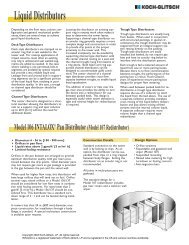
Figure 6: Superfrac Multi-Step Downcomer<br />
<strong>for</strong> High Liquid Rates<br />
Utilizing the Multi-Step Downcomer (MSD) eliminates a portion of the crest height of liquid over the<br />
weir so the resultant froth height on the tray is lower. This provides <strong>additional</strong> capacity <strong>for</strong> the tray by<br />
increasing the amount of disengagement space at a particular design capacity. Because the MSD is<br />
immediately prior to the downcomer (at the exit), the efficiency of the tray is not hampered by any<br />
reduction in liquid residence time on the tray.<br />
For this <strong>debutanizer</strong>, this <strong>revamp</strong> required that the new trays fit up to existing downcomer bolting<br />
bars. No adaptors (Z-bars) were utilized to increase the downcomer sizing. <strong>Koch</strong>-<strong>Glitsch</strong> did not<br />
recommend changing or enlarging the size of the existing downcomers. To make fit-up in the field<br />
easier, <strong>Koch</strong>-<strong>Glitsch</strong> filled in the existing inlet sump. The inlet sump was utilized by the prior trays to<br />
decrease the downcomer aerated backup by providing more room <strong>for</strong> de-aeration in the downcomer.<br />
This feature was not utilized <strong>for</strong> the <strong>revamp</strong> design.<br />
11 of 14 4/20/01
<strong>FCC</strong> DEBUTANIZER REVAMP FOR FLEXIBILITY AND ADDITIONAL CAPACITY<br />
This case study provides an excellent reference on increasing a tower’s capacity, without adding<br />
<strong>additional</strong> downcomers that debit the tray’s efficiency. The interesting thing about this <strong>revamp</strong> is that<br />
the Superfrac trays have gained capacity increase without adding <strong>additional</strong> downcomers or<br />
downcomer area to the tray.<br />
To alleviate some of the concern regarding fouling, <strong>Koch</strong>-<strong>Glitsch</strong> designed some of the trays with antifouling<br />
technology. The top <strong>and</strong> bottom trays in the stripping section were fitted with this technology<br />
to promote “plug flow” across the tray. This would insure that any fouling material was cleaned from<br />
the tray <strong>and</strong> would not stagnate on the tray deck.<br />
BP-Amoco justified the change on increased C 3 recovery, improved RVP control, improved Alkylation<br />
feed quality. This would increase the loadings on the Debutanizer by 6% over the Revamp #1<br />
loadings. As part of the debottlenecking study, they also decided to add a pre-heater to the feed in<br />
order to vaporize some of the feed to relieve the reboiler <strong>and</strong> stripping section loadings <strong>and</strong> to add<br />
operating <strong>flexibility</strong>.<br />
Table III: Operating Parameters: Revamp #1 vs. Revamp #2<br />
Parameter Revamp #1 * Revamp #2 **<br />
Feed (BPD) 46,500 49,025<br />
Tower Pressure (PSIG) 138 130<br />
Tower DP (PSIG) 3.89 3.94<br />
Drum Temperature (°F) 66 94<br />
Top Temperature (°F) 148 139<br />
LPG (BPD) 12,550 15,997<br />
Reflux (BPD) 17,000 31,055<br />
Overhead C 5 (% mol) 3.22 < 0.1<br />
DeC4 Gasoline (BPD) 33,950 33,028<br />
Gasoline RVP (PSIG) 6.6 6.1<br />
Gasoline D-86, °F<br />
IBP 108 117<br />
10% 122 119<br />
30% 156 159<br />
* Operation prior to flood point (from 24 March 99). Tower flooded at reflux of<br />
17,500 BPD.<br />
** Maximum operation to date. Limited by reflux pump.<br />
As part of the <strong>revamp</strong>, <strong>Koch</strong>-<strong>Glitsch</strong> assisted BP-Amoco in the process development <strong>for</strong> the <strong>revamp</strong>.<br />
<strong>Koch</strong>-<strong>Glitsch</strong> also assisted BP-Amoco in the post-<strong>revamp</strong> audit <strong>for</strong> the unit to insure the tower<br />
reached its required capacity. To date, the tower has not been flooded. We have pushed the tower<br />
to the maximum reflux pump capacity, while the tower showed no signs of being close to the flood<br />
point. Revamp #2 testing was executed with the feed vaporizer almost fully by-passed <strong>and</strong> was<br />
12 of 14 4/20/01
<strong>FCC</strong> DEBUTANIZER REVAMP FOR FLEXIBILITY AND ADDITIONAL CAPACITY<br />
limited by the reflux pump. BP-Amoco pushed the unit to the limit while recovering every barrel of<br />
LPG available in the feed.<br />
Economic Analysis<br />
When looking at this comparison, the authors wish to point out that this project began to correct a<br />
capacity deficit. In other words, a <strong>revamp</strong> to h<strong>and</strong>le the anticipated <strong>FCC</strong> gasoline production was<br />
required to achieve the required pay-out <strong>for</strong> the refinery.<br />
After operating <strong>for</strong> approximately nine months now, B.P.-Amoco has achieved several un-<strong>for</strong>seen<br />
advantages <strong>for</strong> the <strong>revamp</strong> that has had a significant impact on unit & refinery economics:<br />
1. Lowering Debutanized Gasoline RVP.<br />
2. Lower than design C 5 content in the alkylate feed stream.<br />
Both of these benefits were unexpected <strong>for</strong> B.P.-Amoco, but had tremendous pay-out.<br />
Shown below is the refinery gasoline pool <strong>for</strong> the Toledo refinery. The blending streams entering into<br />
the gasoline pool come from the <strong>FCC</strong>, Alkylation, Isomerization, Coker, <strong>and</strong> Crude units.<br />
Figure #5: Refinery Gasoline Block Diagram<br />
Light<br />
Heavy<br />
Naphtha<br />
NC4<br />
Light Cat<br />
Re<strong>for</strong>mate<br />
Heavy Cat<br />
Refromate<br />
Total Cat<br />
Re<strong>for</strong>mate<br />
Light Cat<br />
Distillate<br />
Heavy Cat<br />
Distillate<br />
Total Cat<br />
Distillate<br />
Gasoline<br />
Blender<br />
Premium<br />
92<br />
Premium<br />
93<br />
Unleaded<br />
Medium<br />
Grade<br />
Unleaded<br />
Regular<br />
Light<br />
Isocrackate<br />
Subgrade<br />
Motor<br />
Alkylate<br />
Light<br />
Alkylate<br />
The “finished gasoline” to sales has to meet certain distillation properties <strong>for</strong> the local market,<br />
seasonal vapor pressure regulations, <strong>and</strong> sulfur limitations.<br />
13 of 14 4/20/01
<strong>FCC</strong> DEBUTANIZER REVAMP FOR FLEXIBILITY AND ADDITIONAL CAPACITY<br />
Lowering the <strong>FCC</strong> Debutanized gasoline RVP, the largest product stream to the pool, provided BP-<br />
Amoco with <strong>additional</strong> <strong>flexibility</strong> in other units. Since the <strong>FCC</strong> gasoline was the largest volume<br />
contributor to the pool, a deviation was controlled by modifying the smaller streams. After <strong>revamp</strong> #1,<br />
the tower could barely meet the 7.5 PSI RVP limitation to meet the lower RVP summer operations. At<br />
the high RVP, all other pool streams had to be processed at a lower light-ends composition. This was<br />
particularly limiting to the blending <strong>flexibility</strong> at the refinery. This took a particular toll on some of the<br />
other processing units that were already at their limitations.<br />
The second surprise pay-out also dealt with operations <strong>flexibility</strong>. For the Revamp #1, operations<br />
was limited at the maximum feed rate to a reflux of 17-18,000 BPD. At this reflux rate, the trays were<br />
on the verge of flooding <strong>and</strong> the C 5 content in the overhead was 4-5%. The overhead depropanized<br />
butanes are sent directly to the Alkylation plant <strong>for</strong> conversion into gasoline.<br />
The Alkylation plant processes the C 4 ’s from the Debutanizer. Incremental amounts of C 5 in the<br />
overhead consume acid in the Alkylation plant thus increasing the operating cost <strong>for</strong> the Alkylation<br />
plant. For the Revamp #2, the Toledo refinery realized a savings of $1.6 MM USD per year just based<br />
on lower acid consumption.<br />
References<br />
1. Hanson, D.W., Einwich, J.M., <strong>and</strong> Pratt, W., “Revamping High Pressure Fractionators <strong>for</strong><br />
Capacity <strong>and</strong> Efficiency”, Presented at AIChE Spring Meeting, Houston, March 1999.<br />
2. Nutter, D.E. <strong>and</strong> Perry, D., “Sieve Upgrade 2.0 – The MVG Tray”, Preesented at AIChE Spring<br />
Meeting, Houston, March 1995.<br />
3. Hartman, E.L., Hanson, D.W., <strong>and</strong> Weber, B., “<strong>FCC</strong> Main Fractionator Revamp <strong>for</strong> CARB-II<br />
Gasoline Production”, Hydrocarbon Processing, February 1998, pp. 44-49.<br />
4. Golden, S.W., Martin, G.R. <strong>and</strong> Schmidt, K.D., “Field data, new design correct faulty <strong>FCC</strong> tower<br />
<strong>revamp</strong>”, Oil & Gas Journal, May 31, 1993, pp. 54-60.<br />
5. Hanson, D.W. <strong>and</strong> Hartman, E.L., “Ethylene & <strong>FCC</strong>U gas plant <strong>revamp</strong>s <strong>for</strong> higher capacity <strong>and</strong><br />
efficiency”, Presented at the Stone & Webster 11 th Annual Refining Seminar, Dallas, October 5,<br />
1999.<br />
6. Nigg, J.M. <strong>and</strong> Sitton, K.D., “Improve the reliability <strong>and</strong> maintenance of <strong>FCC</strong>U Main fractionator<br />
internals”, World Refining, May-June1999, pp. 87-91.<br />
7. Lockett, M.J., Distillation Tray Fundamentals, Cambridge University Press, New York, 1986.<br />
8. Kister, H.Z., Distillation Operation, McGraw-Hill, Inc., New York, 1990.<br />
14 of 14 4/20/01