

Lornet-36-Long-Range-NLJD-Non-Linear ... - Selcom security
Lornet-36-Long-Range-NLJD-Non-Linear ... - Selcom security
Lornet-36-Long-Range-NLJD-Non-Linear ... - Selcom security

Create successful ePaper yourself
Turn your PDF publications into a flip-book with our unique Google optimized e-Paper software.
ULTRAHIGH FREQUENCY DETECTOR OF<br />
SEMICONDUCTOR COMPONENTS<br />
(NON LINEAR JUNCTION DETECTOR)<br />
«LORNET-<strong>36</strong>»<br />
USER MANUAL
USER MANUAL<br />
1. Introduction<br />
A handheld detector of semiconductor components «LORNET-<strong>36</strong>» (further the detector) is<br />
used for search and detection of electronic devices both in active and switch-off state.<br />
Operating of the detector is based on the property of semiconductor components re-emit the<br />
2 nd and the 3 rd harmonics when radiating them by a probing UHF signal. It is assumed that<br />
maximum response time of semiconductor components of artificial origin is at the 2 nd harmonic of<br />
the probing signal. When radiating oxide films of natural origin maximum response time is at the 3 rd<br />
harmonic of the probing signal.<br />
«LORNET-<strong>36</strong>» detector enables to make analysis of the response time of the objects radiated<br />
both by the 2 nd and the 3 rd harmonics of the probing signals giving the possibility to identify<br />
electronic devices and natural oxide semiconductors reliably.<br />
«LORNET-<strong>36</strong>» finds the best receiving frequency channel free from noise automatically<br />
enabling to operate the device in complicated electromagnet conditions. Digital processing of a<br />
demodulated signal used enables to get maximum sensitivity.<br />
Using of parabolic antenna having great amplification coefficient (20dB at a frequency<br />
<strong>36</strong>00MGz) allowed to increase detecting distance of the nonlinear components and provide their<br />
exact localization in area. For more handiness the detector is equipped with laser illuminating the<br />
spot the antenna is directed on.<br />
There are two types of the signals emitted:<br />
1 Pulse modulation of carrier frequency with on-off time ratio of 160 (Pulse);<br />
2 Pulse modulation of carrier frequency with on-off time ratio of 20 (CW).<br />
CW mode is intended for listening of the detected signal by earphones in order to expose<br />
functioning analog radio-microphone and to use effect of acustic feedback for easy search.<br />
Mode of automatic control of output power simplifies actions of an operator.<br />
«LORNET-<strong>36</strong>» can display signal levels of the 2 nd and the 3 rd harmonics at LED panel<br />
simultaneously. Besides, level of the 2 nd or the 3 rd harmonics can be estimated in turn aurally by<br />
click repetition rate, reproducing via a built-in loudspeaker or wireless earphones.<br />
2. Technical Parameters<br />
2.1. Types of the signal emitted:<br />
3 Pulse modulation of carrier frequency with on-off time ratio of 160 (Pulse);<br />
4 Pulse modulation of carrier frequency with on-off time ratio of 20 (CW).<br />
2.2. Carrier frequency is fixed with pitch of 13 MHz within 3581,5 … <strong>36</strong>07,5 MHz.<br />
Frequency selection is automatic. Possibility of emitting at carrier frequency with minimum noise in<br />
a path of the receiver of the 2 nd harmonic is provided.<br />
2.3. Maximum emitting power with on-off time ratio of 160 (Pulse) no less than 18 W.<br />
2.4. Maximum emitting power with on-off time ratio of 20 (CW) no less than 12 W.<br />
2.5. Emitting power is controlled automatically or manually. Dynamic control range is 22 dB<br />
from maximum value of output power, and is separated into 11 levels.<br />
2.6. The amplification coefficient of transmission antenna on frequency <strong>36</strong>00 MHz no less<br />
than 20 dB, the width of diagram direction on level minus 3 dB does not exceed 16 degrees.<br />
2.7. Sensitivity of receivers no less than minus 110 dBm (first LED illuminating).<br />
2.8. Tuning frequency of receivers is equal to double and triple frequencies of receivers and<br />
amount 72163 … 7215 MHz and 10744,5 … 10822,5 MHz.<br />
2.9. Dynamic range of the receiving path is less than 40 dB.
2.10. Time of continuous operating with built-in lithium-Ion battery at maximum emitting<br />
power is not less than:<br />
- 3 hours for pulse mode (Pulse),<br />
- and 2 hours for CW mode (CW).<br />
2.11. Weight of the device equipped does not exceed 1,6 kg.<br />
2.12. Operation condition:<br />
- ambient temperature 540 єС.<br />
- pressure is not less than 450 mm of mercury.<br />
3. Structure Of The Device, Design And Accessories<br />
3.1. The device consists of the units and accessories listed in the Table:<br />
Name<br />
Q-ty<br />
1. A receiving-transmitting antenna unit combined with a<br />
control panel and built-in lithium-Ion battery. 1<br />
2. A charger for batteries. 1<br />
3. A mains adapter for charger.<br />
4. Wireless telephones, radio receiving device and<br />
headphones. 1<br />
5. User’s manual and passport. 1<br />
6. Package 1<br />
1<br />
2<br />
3<br />
4<br />
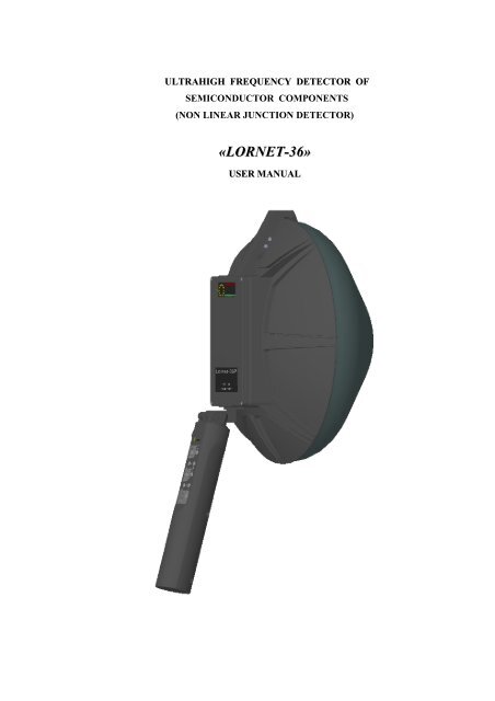
Appearance of the device is shown in Fig. 1, where:<br />
1 – LED indicator;<br />
2 – A receiving-transmitting antenna unit combined with an indicator;<br />
3 – Control panel with a built-in battery;<br />
4 – A parabolic antenna.<br />
Wireless earphones, chargers and additional batteries are not shown in the figure.
4. Purpose Of Basic Units Of The Detector<br />
4.1. A receiving-transmitting antenna unit with built-in LED indicators is used for:<br />
1 Analysis of interfering load of receiving path of the device, which is made at each turn-on<br />
of the detector transmitter, also automatic selection of optimal channel of detector work. Therefore,<br />
during operating when an interfering signal appears (under complicated electromagnet conditions) it<br />
is necessary to turn the detector transmitter off and then to turn it on from time to time, hence<br />
selecting optimum frequency automatically, enabling the best sensitivity and detection range of<br />
semiconductor components.<br />
2 Formation of UHF signal, receipt and digital processing of the 2 nd and the 3 rd harmonics of<br />
radiation frequency. Simultaneous display of signal levels of the 2 nd and the 3 rd harmonics enables<br />
to differ signals of artificial semiconductors, which are a part of electronic devices, from natural<br />
corrosive ones, appearing at oxidation of connecting points of various metals, for sure.<br />
3 Demodulation of response time of the 2 nd and 3 rd harmonics, their amplifying to the level<br />
required for tapping both to earphones and inner dynamic. The possibility to control amplification at<br />
20 dB is provided. Tapping of demodulated signals of the 2 nd and 3 rd harmonics is made by an<br />
operator in turn.<br />
2).<br />
4 Display of levels of a detector power (1), signals of the 2 nd (2) and 3 rd (3) harmonics (Fig.<br />
Fig. 2<br />
4.2. Hinge joint of the receiving-transmitting antenna unit with a knob is designed for<br />
transformation the unit into transportation position. (see Fig.3). Besides, it helps an operator to fix<br />
antenna position convenient for search.<br />
Fig. 3
Fig. 3:<br />
1- A knob of a hinge;<br />
2- Hinge joint;<br />
4.3. A control panel is used to control operating of the detector. It consists of a case combined<br />
with a battery and fixed on the telescopic arm. A control board, buttons for operating modes control<br />
and display LEDs are in the case. Control buttons are divided into two groups by functional feature:<br />
«AUDIO» placed in the upper half of the panel and «POWER RF», in the lower part. Control panel<br />
is shown in Fig.4.<br />
Fig. 4<br />
1 – Indicators and LSTN button for switching of acoustic display to output on the 2 nd or 3 rd<br />
harmonics.<br />
2 – OUT button and indicators for switching acoustic output to earphones or a built-in<br />
loudspeaker.<br />
3 – RF button and indicators for switching emission types of a probing signal (CW –<br />
continuous, PULSE – pulse).<br />
4 – The following buttons are referred to «POWER RF» group: indicators and PWR button<br />
for turn on/off a transmitter of the probing signal. When it is turned on an automatic mode of output<br />
power control (AUTO) is set by default. To switch over to a manual mode of output power control<br />
(MNL) press one of LEVEL buttons when a transmitter is turned on. To return to an automatic<br />
mode turn a transmitter off and then turn it on.<br />
5,6 – Indicator and ATT button for control of frequency receivers of the 2 nd and 3 rd harmonics.<br />
Luminescence of each LED indicates reduction of receivers’ frequency at 4 dB. Hence, maximum<br />
frequency reduction by an ATT button can arrange 20 dB.<br />
7,8 – LEVEL buttons for control of emitted signal power in MNL mode. It is possible to set<br />
required power level by pressing LEVEL button in AUTO mode before a probing signal transmitter<br />
is turned on.<br />
9,10 – Volume buttons for volume control.<br />
An indicator functions of control panel. Continuous light of the indicator corresponds to «ON»<br />
position, absence of light – «OFF» position. Simultaneous flickering of all indicators on the panel<br />
shows that a battery is discharged, it needs to be replaced.
4.4. On the side surface of the control panel (see 1 in Fig. 5) a slide-type power switch is<br />
placed. A slide position corresponding to «ON» is marked by a contrast point.<br />
4.5. Batteries charging is made by a mains adaptor and mains charger for batteries included<br />
into delivery set. Use of other charging devices is not permitted. It is necessary to put the pin cutoff<br />
point into detector handle butt-end.<br />
4.6. When switching charger into plug socket, the red light illuminates on case of charger,<br />
while charging. After full battery charging red light is turning off and green light illuminates.<br />
Charging time of completely discharged operative accumulator does not exceed 5 hours.<br />
4.7. Wireless telephones consist of a receiving device and earphones.<br />
Appearance of a receiving device and position of control units are shown in Fig.5<br />
Operating order of a receiving device.<br />
1 Using a mains adaptor included into delivery set, make full charging of a built-in battery<br />
by charge indicator.<br />
Use of another mains adaptors are forbidden.<br />
2 Connect head phones through a corresponding socket of a receiving device.<br />
3 Turn a receiving device ON by a slide-type switch (control by a turn-ON indicator).<br />
4 Using volume control set comfortable volume level.<br />
5 If a receiving device is turned on when the detector “<strong>Lornet</strong>-<strong>36</strong>” is off, then there is only a<br />
noise signal in the head phones at higher volume. After turning on acoustic indicator signals<br />
corresponding to operating mode of the detector appear in the earphones.<br />
Индикатор включения<br />
(светится при включении)<br />
Гнездо для подключения<br />
телефонов<br />
Гнездо сетевого<br />
адаптера<br />
Регулятор<br />
громкости<br />
Индикатор заряда<br />
(светится во время заряда)<br />
Движковый<br />
выключатель<br />
Fig. 5
5. Safety Measures<br />
5.1. By requirements of electric safety the detector is referred to protection class 1.<br />
5.2. Persons having taken instructing for safety measures while operating electric devices and<br />
measuring devices with open radiators of RF-energy are permitted to work.<br />
5.3. Density level of power flow UHF radiation of “<strong>Lornet</strong>-<strong>36</strong>” is shown in Table:<br />
Measurement<br />
Mode<br />
Distance avg.<br />
µW/cm 2<br />
Distance max<br />
µW/cm 2<br />
Maximum<br />
radiation<br />
direction<br />
Backward<br />
semisphere;<br />
0,3m<br />
Pulse 3,6 9,<strong>36</strong><br />
CW 44,1 77,8<br />
Pulse 0,19 1,7<br />
CW 1,88 7,7<br />
Note: data received using electromagnetic radiation indicator P3-31.<br />
5.4. Direction of the antenna at people nearby on being under radiation is not recommended.<br />
6. Operating Order<br />
6.1. Remove the detector from the package, charge a battery if necessary. While transporting<br />
the device at negative temperature it is necessary to keep the device at room temperature not less<br />
than 30 min, not turning the device on.<br />
6.2. Turn «LORNET-<strong>36</strong>» on by a power switch placed on the knob. At that 2 nd and 3 rd<br />
indicators on the control panel light, indicating that power of the detector is turned on. One yellow<br />
LED should light on the antenna unit (a circle scale of power indicator of the probing signal). Its<br />
initial position corresponds to maximum power of the probing signal. Here a probing signal<br />
transmitter is off (it is turned on after pressing PWR button only). Indicators of the 2 nd and 3 rd<br />
harmonics should not light (flashing of the first LEDs of 2 nd and 3 rd of scales is permitted).<br />
6.3. Turn a probing signal transmitter on pressing PWR button. Here a pulse mode of the<br />
transmitter and an automatic mode of signal power switch on. Probing signal power changes<br />
according to signal level at the input of the receiver 2 nd harmonic. In the given mode sound<br />
information of the 2 nd harmonic signal response is put to the dynamic or head phones.<br />
After turning 3 rd mode by pressing LSTN button automatic regulation of output power of the<br />
receiver will occur, depending on signal level at the input of the receiver 3 rd harmonic. Sound<br />
information of the 3 rd harmonic signal response is put to the dynamic or head phones.<br />
To switch over to manual mode of power control of the probing signal (MNL indicator lights)<br />
press one of LEVEL buttons after a probing signal transmitter is turned on. Turn a probing signal<br />
transmitter off and then turn it on by pressing PWR button for reverse switch over.<br />
If necessary to tap a response signal by the third harmonic turn 3 rd mode on using LSTN<br />
button on the control panel.<br />
Normally while operating in rooms with a lot of electronic devices, decrease level of the
probing signal for 2-4 points counterclockwise from the initial one. Optimum level of the probing<br />
signal is reached by experimental way.<br />
6.4. Simultaneous flashing of all indicators on the control panel indicates that a battery is<br />
discharged and need to be replaced urgently. At that power should be turned off and a batteryreplaced.<br />
6.5. If a response signal for telephones needs to be tapped, switch over acoustic indication in a<br />
mode of head phones, for that press the corresponding button on the control panel and turn wireless<br />
phones on.<br />
Attention:<br />
1). Do not direct the antenna towards an operator and people nearby.<br />
2). While operating the device observe state of batteries constantly replacing them in-time (by<br />
the indicator signal). The device must be kept in a charged state.<br />
3). Charging should be done in a charger only, included to the delivery set.<br />
4). Use of undue chargers are forbidden.<br />
7. Search Recommendation<br />
7.1. If possible remove electronic devices from the room examined. If it is impossible<br />
examination should be done at decreased power emitted.<br />
7.2. Set maximum power emitted and one of the operating modes of the receiver.<br />
7.3. Direct an antenna on the surface examined using laser spot. Slowly moving antenna unit<br />
parallel to the surface examined and changing orientation of antennas, analyze change of nature of<br />
the signal received by the 2 nd and 3 rd harmonics by the indicator visually (aurally click repetition<br />
rate should be maximum).<br />
7.4. Analysis of levels of the receiving signal reflected by the 2 nd and 3 rd harmonics is made by<br />
number of LEDs lit on the corresponding indicator scale.<br />
7.5. Remove antenna unit from the surface examined or decrease output power and repeat<br />
measurements stated in cl.7.4. of the present manual. Decrease receivers’ frequency by using ATT<br />
button for more exact localization and anti jamming.<br />
7.6. When artificial р-n transition is found, as a rule, stable glowing of the indicator LEDs by<br />
the 2 nd harmonic of the signal reflected. While rapping a supposed place of p-n transition, readings<br />
of LEDs do not change.<br />
7.7. When natural р-n transition is found, there is stable light of LEDs of indicators by the 3 rd<br />
harmonic of the signal reflected. While rapping the surface examined intensively, readings of<br />
indicators by the 3 rd harmonic do change, as a rule.<br />
The search technique offered does not contain all nuances in exact cases, and it is a<br />
recommendation only.
CERTIFICATE<br />
1. General<br />
1.1. Before operating study User Manual for «LORNET-<strong>36</strong>» thoroughly.<br />
1.2. The Certificate is included to the delivery set and should be always near it.<br />
1.3. If the device is sent for repair or other place during operation the Certificate is to be<br />
passed with the device.<br />
1.4. Marks in the Certificate should be done in-time.<br />
1.5. All records in the Certificate should be made by ink only, distinctly and carefully.<br />
Erasures, blots and corrections unauthorized are not permissible.<br />
1.6. It is forbidden to make any notes or records on fields and a cover of the Certificate.<br />
2. Delivery set<br />
Name Q-ty Serial No Notes<br />
A receiving-transmitting antenna unit<br />
with control panel<br />
1<br />
A charger for a battery 1<br />
A mains adaptor 1<br />
Wireless phones included: a receiver<br />
and earphones<br />
User manual 1<br />
Certificate 1<br />
Package 1<br />
Option:<br />
1<br />
3. Warranty<br />
3.1. Warranty period of «LORNET-<strong>36</strong>» detector is 24 months upon supply to the customer.<br />
3.2. Expected life time is 6 years.<br />
3.3. If the device fails during warranty period provided the customer follows all rules for<br />
operation, transportation and storage, the manufacturer is to make repair free of charge or replace<br />
the device.<br />
3.4. Warranty does not cover power elements.


