Hybrid finite element -- wave based method for steady-state acoustic ...
Hybrid finite element -- wave based method for steady-state acoustic ...
Hybrid finite element -- wave based method for steady-state acoustic ...

Create successful ePaper yourself
Turn your PDF publications into a flip-book with our unique Google optimized e-Paper software.
<strong>Hybrid</strong> <strong>finite</strong> <strong>element</strong> – <strong>wave</strong> <strong>based</strong> <strong>method</strong><br />
<strong>for</strong> <strong>steady</strong>-<strong>state</strong> <strong>acoustic</strong> analysis<br />
B. van Hal 1 , C. Vanmaele 1 , W. Desmet 1 , P. Silar 2 , H.-H. Priebsch 2<br />
1 K.U.Leuven, Dept. Mech. Engrg., Division PMA<br />
Celestijnenlaan 300 B, B-3001, Heverlee, Belgium<br />
e-mail: wim.desmet@mech.kuleuven.ac.be<br />
2 ACC Acoustic Competence Center G.m.b.H.,<br />
Inffeldgasse 25, A-8010 Graz, Austria<br />
Abstract<br />
This paper considers the extension of the frequency application range of the <strong>finite</strong> <strong>element</strong> <strong>method</strong> (FEM)<br />
applied to <strong>steady</strong>-<strong>state</strong> <strong>acoustic</strong> problems. This is achieved by the hybrid coupling of the FEM with the <strong>wave</strong><br />
<strong>based</strong> <strong>method</strong> (WBM). The WBM is a computationally efficient alternative <strong>for</strong> the FEM, but it is restricted<br />
to <strong>acoustic</strong> problems of moderate geometrical complexity. The hybrid <strong>finite</strong> <strong>element</strong> – <strong>wave</strong> <strong>based</strong> <strong>method</strong><br />
(HFE-WBM) benefits from the advantageous features of both <strong>method</strong>s. These are the high geometrical<br />
flexibility of the FEM and the computational efficiency of the WBM. The potential of the HFE-WBM to<br />
provide more accurate predictions <strong>for</strong> higher frequencies than the FEM is illustrated <strong>for</strong> the validation of a<br />
numerical example of a 2D <strong>acoustic</strong> car cavity.<br />
1 Extension of frequency application range of deterministic <strong>method</strong>s<br />
The <strong>finite</strong> <strong>element</strong> <strong>method</strong> (FEM) is a commonly used deterministic numerical <strong>method</strong> <strong>for</strong> the analysis<br />
of <strong>steady</strong>-<strong>state</strong> <strong>acoustic</strong> problems [1, 2, 3]. The <strong>finite</strong> <strong>element</strong> (FE) procedure consists of subdividing an<br />
<strong>acoustic</strong> domain in a large number of small non-overlapping subdomains, i.e. the <strong>finite</strong> <strong>element</strong>s. Within<br />
each <strong>element</strong>, a linear combination of simple (polynomial) basis functions approximates the exact pressure<br />
distribution. The FEM exhibits a large geometrical flexibility since the FE subdivision is possible <strong>for</strong> most<br />
practical engineering problems. However, the FEM is restricted to the low-frequency application range due<br />
to the increasing model size and the subsequent computational ef<strong>for</strong>ts, which are required to keep the FE<br />
approximation errors within reasonable limits.<br />
The FE approximation errors consist of interpolation errors and dispersion errors [3]. Especially, the dispersion<br />
errors gain importance at higher frequencies. The difference between the numerical <strong>wave</strong>number and<br />
the physical <strong>wave</strong>number causes the dispersion errors. In order to control this type of error, the FE model<br />
sizes and subsequent computational costs increase drastically <strong>for</strong> increasing frequencies.<br />
A vast amount of research is currently spent on extending the frequency application range of the FEM. A<br />
common feature of these extensions is that the computational costs <strong>for</strong> increasing frequencies is reduced by<br />
controlling the dispersion errors more efficiently. Several classes of extensions exist, namely<br />
• the stabilized <strong>method</strong>s, such as the Galerkin least-squares FEM [4] and the quasi-stabilized FEM [5],<br />
• the generalized <strong>method</strong>s, such as the partition-of-unity FEM [6] and the <strong>element</strong>-free Galerkin<br />
<strong>method</strong> [7],<br />
• and the multi-scale <strong>method</strong>s, such as the residual-free bubbles <strong>method</strong> [8] and the discontinuous<br />
enrichment <strong>method</strong> [9].<br />
1629
1630 PROCEEDINGS OF ISMA2004<br />
An alternative <strong>for</strong> the FEM is the class of indirect Trefftz <strong>method</strong>s [10, 11, 12]. These <strong>method</strong>s apply a<br />
priori knowledge of the exact solution. The approximation solution satisfies the governing domain equations<br />
and violates only the boundary conditions, so that the resulting numerical models are much smaller<br />
than FE models. Moreover, the a priori knowledge of the exact solution includes knowledge of the physical<br />
<strong>wave</strong>number such that the dispersion errors are reduced substantially compared with the FEM. Several indirect<br />
Trefftz <strong>method</strong>s have emerged <strong>for</strong> structural-dynamic and <strong>acoustic</strong> applications, such as the spectral<br />
FEM [13], the <strong>wave</strong>guide FEM [14], the Trefftz least-squares FEM [15], the hybrid-Trefftz FEM [16], the<br />
<strong>wave</strong> <strong>based</strong> <strong>method</strong> (WBM) [17] and the variational theory of complex rays [18].<br />
The reader is referred to [19] <strong>for</strong> a detailed overview of deterministic <strong>method</strong>s with an extended frequency<br />
application range compared with the FEM. This paper focuses on the hybrid coupling between the FEM and<br />
the WBM <strong>for</strong> <strong>acoustic</strong> applications. The resulting hybrid <strong>finite</strong> <strong>element</strong> – <strong>wave</strong> <strong>based</strong> <strong>method</strong> (HFE-WBM)<br />
is proposed to benefit from the advantageous features of both <strong>method</strong>s [20, 21]. These are the geometrical<br />
flexibility of the FEM and the computational efficiency of the WBM.<br />
The paper is arranged as follows. Section 2 introduces the mathematical description of an <strong>acoustic</strong> problem.<br />
Section 3 provides the theoretical background of the HFE-WBM. Section 4 illustrates the potential of the<br />
HFE-WBM to provide more accurate approximations at higher frequencies than the FEM. Finally, section 5<br />
summarizes the conclusions and provides some recommendations <strong>for</strong> further investigations.<br />
2 Acoustic problem definition<br />
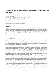
Consider a 3-dimensional (3D) <strong>acoustic</strong> cavity, of which the dimension in the z-direction is in<strong>finite</strong>. If the<br />
boundary conditions do not vary in the z-direction, then the 3D <strong>acoustic</strong> problem can be reduced to the 2D<br />
problem shown in figure 1.<br />
The bounded 2D <strong>acoustic</strong> problem consists of the domain Ω surrounded by the closed boundary Γ. The<br />
boundary Γ is composed of two non-overlapping parts (Γ = Γ v ∪ Γ Z ), namely the part Γ v with the prescribed<br />
normal velocity ¯v n and the part Γ Z with the prescribed normal impedance ¯Z. The homogeneous Helmholtz<br />
equation<br />
(<br />
∆ + k<br />
2 ) p(r) = 0, ∀ r ∈ Ω (1)<br />
governs the <strong>steady</strong>-<strong>state</strong> dynamic pressure p at position r in domain Ω, together with the natural boundary<br />
conditions<br />
v n (r) = ¯v n (r), ∀ r ∈ Γ v (2)<br />
and the mixed boundary conditions<br />
¯Z(r)v n (r) = p(r), ∀ r ∈ Γ Z . (3)<br />
Figure 1: Bounded 2D <strong>acoustic</strong> problem
MEDIUM AND HIGH FREQUENCY TECHNIQUES 1631<br />
∆ = ∂ 2 /∂x 2 + ∂ 2 /∂y 2 represents the Laplace operator and k = ω/c the physical <strong>wave</strong>number with the<br />
circular frequency ω and the speed of sound c. The normal velocity v n is given by<br />
v n (r) = n T v(r), ∀ r ∈ Γ, (4)<br />
where n represents the normal vector depicted in figure 1, with the transpose operator • T , and where v<br />
represents the velocity vector, which is governed by the equation of motion<br />
v(r) =<br />
i ∇p(r), ∀ r ∈ Ω, (5)<br />
ρω<br />
with the unit imaginary number i = √ −1 and with the gradient operator ∇ = [∂/∂x ∂/∂y] T .<br />
3 Theory on hybrid <strong>finite</strong> <strong>element</strong> – <strong>wave</strong> <strong>based</strong> <strong>method</strong><br />
3.1 Review of <strong>finite</strong> <strong>element</strong> <strong>method</strong><br />
The FEM applies the following strategy to approximate the exact solution of the 2D <strong>acoustic</strong> problem.<br />
1. The problem domain Ω is subdivided in a large number of n e non-overlapping <strong>element</strong>s Ω e . Each<br />
<strong>element</strong> boundary Γ e is composed of three non-overlapping parts Γ e = Γ e v ∪ Γ e Z ∪ Γe i , namely the<br />
intersections with the problem boundaries Γ e v = Γ e ∩ Γ v and Γ e Z = Γe ∩ Γ Z and the common interface<br />
of two adjacent <strong>element</strong>s Γ e i .<br />
2. Within each <strong>element</strong> Ω e , a linear combination of simple (polynomial) basis functions, stored in the<br />
row vector N, approximates the exact pressure field p<br />
p(r) ≈ ˆp(r) = N(r) p e , ∀ r ∈ Ω e . (6)<br />
The column vector p e contains the unknown contribution factors. These <strong>for</strong>m the FE degrees of<br />
freedom (DOFs), which are generally nodal values of the pressure approximation ˆp. The derived<br />
velocity approximation ˆv satisfies the equation of motion (5).<br />
3. The pressure approximation ˆp is continuous over <strong>element</strong> boundaries but it violates the governing<br />
equations in (1) – (3). The violation of these relations are en<strong>for</strong>ced to zero in an integral sense by<br />
application of the following variational principle.<br />
Consider the energy functional J e defined <strong>for</strong> each <strong>element</strong> Ω e<br />
∫<br />
J e = Π e + ˆp n T v i dΓ<br />
Γ e i<br />
∫<br />
∫<br />
∫<br />
∫<br />
with Π e = 1 2<br />
eˆv T iρω ˆv dΩ + 1 ik<br />
2<br />
Ω Ωeˆp ρc ˆp dΩ + ˆp ¯v n dΓ + 1<br />
Γ e 2<br />
v<br />
Γ e Z<br />
ˆp ¯Z −1 ˆp dΓ,<br />
where v i represents the unknown velocity at the interface Γ e i . The stationary point of J e en<strong>for</strong>ces the<br />
violation of (1) – (3) to zero on <strong>element</strong> level<br />
∫<br />
δJ e = δΠ e + δp n T v i dΓ = 0<br />
Γ e i<br />
∫<br />
∫<br />
with δΠ e = δv T iρω ˆv dΩ + δp ik ∫<br />
Ω e Ω e ρc ˆp dΩ +<br />
Γ e v<br />
∫<br />
δp ¯v n dΓ +<br />
Γ e Z<br />
δp ¯Z −1 ˆp dΓ.<br />
The integral contributions with the interface velocity v i of two adjacent <strong>element</strong>s cancel out each other<br />
at the time of assembling all <strong>element</strong> FE models into one global FE model. There<strong>for</strong>e, this integral<br />
(7)<br />
(8)
1632 PROCEEDINGS OF ISMA2004<br />
contribution is not considered further. The small perturbations δp and δv result from small arbitrary<br />
perturbations δp e of the FE DOFs p e<br />
δp(r) = N(r) δp e and δv(r) = i<br />
ρω ∇N(r) δpe , ∀ r ∈ Ω e . (9)<br />
4. The <strong>element</strong> FE model follows from (i) the substitution of ˆp, ˆv, δp and δv in the integral relation (8),<br />
from (ii) multiplication with iρω and from (iii) the requirement that this relation holds <strong>for</strong> arbitrary<br />
perturbations δp e .<br />
5. The assembly of all <strong>element</strong> FE models results in the following FE model <strong>for</strong> 2D <strong>acoustic</strong> problems<br />
(<br />
−ω 2 M + iω C + K ) p E = −iω v n (10)<br />
⋃n e ∫<br />
⋃n e ∫<br />
with M = N T c −2 N dΩ, C =<br />
e=1 Ω e e=1<br />
⋃n e ∫<br />
⋃n e ∫<br />
K = (∇N) T (∇N) dΩ and v n =<br />
Ω e<br />
e=1<br />
e=1<br />
Γ e Z<br />
Γ e v<br />
ρ N T ¯Z−1 N dΓ,<br />
ρ N T ¯v n dΓ.<br />
The model matrices M, C and K represent the <strong>acoustic</strong> mass, damping and stiffness matrix. The model<br />
vector v n takes into account the <strong>acoustic</strong> excitation, which consists of a non-zero prescribed normal<br />
velocity distribution. The column vector p E collects all FE DOFs.<br />
6. The model matrices are generally sparse. This allows the application of efficient ’skyline’ solvers to<br />
compute the FE DOFs in p E .<br />
3.2 Review of <strong>wave</strong> <strong>based</strong> <strong>method</strong><br />
The WBM applies the following strategy to approximate the exact solution of the 2D <strong>acoustic</strong> problem.<br />
1. The problem domain Ω is subdivided in a small number of n w non-overlapping convex subdomains<br />
Ω w . Similar to the FEM, each subdomain boundary Γ w is composed of three non-overlapping parts<br />
Γ w = Γ w v ∪ Γ w Z ∪ Γw i .<br />
2. Within each subdomain Ω w , a linear combination of Trefftz basis functions, stored in the row vector<br />
Φ, approximates the exact pressure field p<br />
p(r) ≈ ˆp(r) = Φ(r) q w , ∀ r ∈ Ω w . (11)<br />
The column vector q w contains the unknown <strong>wave</strong> <strong>based</strong> (WB) contribution factors, which are not<br />
nodal values of the pressure approximation ˆp as is the case <strong>for</strong> the FEM. The Trefftz basis functions<br />
belong to the following set of propagating and evanescent <strong>wave</strong> functions<br />
Φ rs (r) = cos(k r x) cos(k s y) e −ikrsz , with k r = rπ , k s = sπ , k rs = ± √ k<br />
L x L 2 − kr 2 − ks,<br />
2<br />
y<br />
Φ tu (r) = e −iktux cos(k t y) cos(k u z), ” k t = tπ<br />
L y<br />
, k u = uπ<br />
L z<br />
, k tu = ±<br />
Φ vw (r) = cos(k w x) e −ikvwy cos(k v z), ” k v = vπ<br />
L z<br />
, k w = wπ<br />
L x<br />
, k vw = ±<br />
√<br />
k 2 − kt 2 − k2 u,<br />
√<br />
k 2 − kv 2 − kw.<br />
2<br />
The numerical <strong>wave</strong>numbers k • depend on the dimensions (L x , L y , L z ) of the (preferable) smallest<br />
rectangular domain, which encloses the actual subdomain Ω w . The r, s, t, u, v and w represent integer<br />
sets [0, n • ], which are limited from above by the following truncation numbers n •<br />
(12)<br />
with a user defined truncation number T .<br />
n r<br />
L x<br />
≈ n s<br />
L y<br />
≈ n t<br />
L y<br />
≈ n u<br />
L z<br />
≈ n v<br />
L z<br />
≈ n w<br />
L x<br />
≥ T k π<br />
(13)
MEDIUM AND HIGH FREQUENCY TECHNIQUES 1633<br />
3. The pressure approximation satisfies the Helmholtz equation (1), but violates the boundary conditions<br />
in (2) and (3) and the pressure and velocity continuity across WB subdomain boundaries. A variational<br />
principle en<strong>for</strong>ces the violations of these relations to zero in an integral sense.<br />
The WBM applies a direct approach to couple WB subdomains. In case of two WB subdomains Ω 1 and<br />
Ω 2 , the continuity conditions are considered as prescribed essential and natural boundary conditions<br />
as follows<br />
pressure continuity: p 1 = p 2 (essential BC † <strong>for</strong> Ω 1 ),<br />
(14)<br />
velocity continuity: vn 2 = −vn 1 (natural BC <strong>for</strong> Ω 2 ),<br />
where superscripts • 1 and • 2 refer to subdomains Ω 1 and Ω 2 . The extension <strong>for</strong> n w > 2 subdomains<br />
is straight<strong>for</strong>ward and, there<strong>for</strong>e, is not considered further.<br />
The following variational principle is employed. Consider the energy functional E 1 and E 2<br />
∫<br />
∫<br />
E 1 = Π 1 + ˆv n 1 (ˆp 1 − ˆp 2 ) dΓ and E 2 = Π 2 − ˆp 2 ˆv n 1 dΓ (15)<br />
Γ 1 i<br />
with the energy functional Π w (w = 1, 2) according to (7) and where the approximation of the normal<br />
velocity ˆv n w satisfies relation (4) and the equation of motion (5). The stationary points of E 1 and E 2<br />
en<strong>for</strong>ces the above violations to zero<br />
∫<br />
δE 1 = δΠ 1 +<br />
Γ 1 i<br />
∫<br />
δE 2 = δΠ 2 − δp 2 ˆv n 1 dΓ,<br />
Γ 2 i<br />
Γ 2 i<br />
∫<br />
δvn 1 (ˆp 1 − ˆp 2 ) dΓ + δp 1 ˆv n 1 dΓ,<br />
Γ 1 i<br />
with δΠ w according to (8). The small perturbations δp w and δv w n result from small arbitrary perturbations<br />
δq w of the WB DOFs q w<br />
δp w (r) = Φ(r) δq w , ∀ r ∈ Ω w and δv w n(r) = i<br />
ρω nT ∇Φ(r) δq w , ∀ r ∈ Γ w . (17)<br />
The application of several mathematical manipulations ‡ trans<strong>for</strong>ms the integral <strong>for</strong>mulations in (16)<br />
into the boundary integral <strong>for</strong>mulations<br />
∫<br />
∫<br />
∫<br />
δE 1 = δp 1 (ˆv n 1 − ¯v n ) dΓ+ δp 1 (ˆv n 1 − ¯Z −1 ˆp 1 ) dΓ− δvn 1 (ˆp 1 − ˆp 2 ) dΓ = 0,<br />
∫<br />
δE 2 =<br />
Γ 1 v<br />
Γ 2 v<br />
∫<br />
δp 2 (ˆv n 2 − ¯v n ) dΓ+<br />
Γ 1 Z<br />
Γ 2 Z<br />
∫<br />
δp 2 (ˆv n 2 − ¯Z −1 ˆp 2 ) dΓ+<br />
Γ 1 i<br />
Γ 2 i<br />
δp 1 (ˆv 1 n + ˆv 2 n) dΓ = 0.<br />
4. The substitution of ˆp w , ˆv n, w δp w and δvn w in the boundary integral <strong>for</strong>mulations, together with the<br />
requirement that the boundary integral <strong>for</strong>mulation holds <strong>for</strong> arbitrary perturbations δq w , results in the<br />
following WB model <strong>for</strong> 2D <strong>acoustic</strong> problems with two convex subdomains<br />
[<br />
(A<br />
1<br />
v + A 1 Z + Q1 b ) ] { } { }<br />
Q1 2 q<br />
1 b<br />
1<br />
v<br />
Q 2 1 (A 2 v + A 2 Z + Q2 b ) =<br />
q 2 b 2 v<br />
i<br />
∫<br />
ρω nT ∇Φ dΓ, b w v = Φ T ¯v n dΓ,<br />
Γ w v<br />
( )<br />
i<br />
Φ T<br />
Γ w ρω nT ∇Φ − ¯Z −1 Φ dΓ,<br />
Z<br />
∫<br />
Q 1 b = − i (<br />
n T ∇Φ ) ∫<br />
T<br />
Φ dΓ, Q<br />
1<br />
ρω<br />
2 =<br />
∫<br />
with A w v = Φ T<br />
Γ w v<br />
∫<br />
A w Z =<br />
Q 2 b = ∫<br />
Γ 2 i<br />
Γ 1 i<br />
Φ T<br />
i<br />
ρω nT ∇Φ dΓ, and Q 2 1 =<br />
∫<br />
Γ 1 i<br />
Γ 2 i<br />
i<br />
( ) n 1 T T<br />
∇Φ<br />
1 Φ 2 dΓ,<br />
ρω<br />
Φ 2 T<br />
i<br />
ρω n1 T<br />
∇Φ 1 dΓ.<br />
† boundary condition<br />
‡ the equation of motion (5), integration by parts, the divergence theorem, the Helmholtz equation (1) and multiplication by -1<br />
(16)<br />
(18)<br />
(19)
1634 PROCEEDINGS OF ISMA2004<br />
A w v and b w v take into account the <strong>acoustic</strong> excitation and A w Z the mixed boundary conditions. Qw b<br />
represent the back-coupling matrices and Q 1 2 and Q 2 1 the coupling matrices.<br />
5. The model matrices are small compared with FE models, but fully populated, frequency dependent<br />
and complex. Only direct <strong>method</strong>s can be employed to solve the linear system in (19). The resulting<br />
WB DOFs in q 1 and q 2 are not nodal pressure approximations as is the case <strong>for</strong> the FEM. The WB<br />
pressure approximation ˆp at discrete positions r follows from an additional post-processing step using<br />
relation (11).<br />
3.3 Comparison of <strong>finite</strong> <strong>element</strong> <strong>method</strong> and <strong>wave</strong> <strong>based</strong> <strong>method</strong><br />
This paragraph compares briefly the advantages and disadvantages of the FEM and the WBM. The features<br />
of interest are the model properties, the accuracy and the practical applicability.<br />
• Comparison of model properties:<br />
– The FEM requires substantially larger models than the WBM in order to obtain the same level<br />
of accuracy. However, the FE model matrices are sparsely populated, which allows the use of<br />
efficient ’skyline’ solvers. The WB model matrices are dense such that only direct solvers are<br />
applicable.<br />
– The solution of the FE model is computationally more expensive than its generation. In case of<br />
the WBM, the major part of the computational burden is involved with the WB model generation.<br />
• Comparison of accuracy:<br />
The WBM is computationally more efficient than the FEM, certainly <strong>for</strong> increasing frequencies [17,<br />
22, 23, 24]. The WBM suffers less from dispersion errors. Consequently, it exhibits an improved<br />
convergence behaviour as compared to the FEM.<br />
• Comparison of practical applicability:<br />
The FEM is well suited <strong>for</strong> most practical engineering problems due to its highly geometrical flexibility.<br />
However, it is limited to the low-frequency range due to vastly growing computational costs<br />
necessary to control the dispersion errors at higher frequencies. The WBM is computationally more<br />
efficient than the FEM in case of a WB domain subdivision with only a small number of subdomains.<br />
However, if the number of subdomains increases <strong>for</strong> reasons of geometrical complexity, the computational<br />
efficiency is less pronounced. This feature restricts the application of the WBM to <strong>acoustic</strong><br />
problems of moderate geometrical complexity.<br />
The comparison of the practical applicability shows some advantageous and disadvantageous features of both<br />
<strong>method</strong>s, which <strong>for</strong>m the motivation to investigate the hybrid coupling between the FEM and the WBM.<br />
The HFE-WBM, which incorporates this hybrid coupling, is proposed in order to extend the frequency<br />
application range of the FEM without loss of geometrical flexibility as is the case <strong>for</strong> the WBM. The next<br />
paragraph presents the theoretical background of this new <strong>method</strong>.<br />
3.4 <strong>Hybrid</strong> FE-WB modelling <strong>based</strong> on equivalent velocity frame<br />
The HFE-WBM employs an indirect coupling approach <strong>based</strong> on the Lagrange multiplier technique (LMT)<br />
[1]. The LMT allows the coupling of two noncon<strong>for</strong>ming approximation fields at the expense of an additional<br />
interface approximation. The procedure is as follows.
MEDIUM AND HIGH FREQUENCY TECHNIQUES 1635<br />
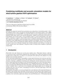
1. A frame Γ F is placed at the common interface between the FE submodel Ω E and the WB submodel<br />
Ω W , on which the additional interface field or frame field is introduced. Assume that the WB submodel<br />
consists of one convex WB subdomain Ω w <strong>for</strong> the sake of simplicity. The frame Γ F is subdivided in<br />
n f non-overlapping frame <strong>element</strong>s Γ f . The frame <strong>element</strong>s Γ f match geometrically with the edges<br />
of adjacent <strong>finite</strong> <strong>element</strong>s Ω e . Figure 2 illustrates this modelling step graphically.<br />
2. The LMT en<strong>for</strong>ces weakly the following continuity conditions at the frame Γ F<br />
pressure continuity:<br />
equivalent velocity continuity:<br />
ˆv e n(r) −<br />
ˆp e (r) = p f (r) = ˆp w (r),<br />
−1 ¯Z<br />
f<br />
ˆp e (r) = ˆv eq(r) f = −ˆv n(r) w −<br />
−1 ¯Z<br />
f<br />
ˆp w (r),<br />
(20)<br />
where p f represents the unknown frame pressure and ˆv f eq represents the approximation of the equivalent<br />
frame velocity, i.e. the additional frame approximation. The equivalent velocity continuity is the<br />
combination of the velocity continuity and the pressure continuity divided by a user defined frame<br />
impedance ¯Z f . The application of this continuity condition stabilizes the FE submodel and the WB<br />
submodel in order to avoid singularity problems at subdomain eigenfrequencies.<br />
3. A linear combination of simple basis functions, stored in the row vector N f , approximates the exact<br />
equivalent frame velocity v f eq<br />
v f eq(r) ≈ ˆv f eq(r) = N f (r) v f , ∀ r ∈ Ω f . (21)<br />
The frame basis functions in N f belong to the set of hierarchical polynomial functions <strong>based</strong> on midside<br />
nodes, which are indicated by ⋄ in figure 2. Consequently, the unknown contribution factors in the<br />
column vector v f do not equal the nodal values of the equivalent frame velocity approximation ˆv f eq.<br />
4. Separate variational principles are employed <strong>for</strong> the FE submodel and the WB submodel.<br />
(a) The energy functional J e in (7) is augmented as follows <strong>for</strong> the <strong>finite</strong> <strong>element</strong>s adjacent to the<br />
frame Γ F ∫<br />
L e = J +∫<br />
e ˆv eq f (ˆp e − p f ) dΓ + 1<br />
{Γ e ∩Γ f 2<br />
ˆp e ¯Z−1 f<br />
ˆp e dΓ. (22)<br />
}<br />
{Γ e ∩Γ f }<br />
The stationary point of L e en<strong>for</strong>ces the violation on the Helmholtz equation (1), on the boundary<br />
conditions in (2) and (3) and on the continuity conditions in (20) to zero<br />
∂J e ∂J<br />
e<br />
⎫ ⎧ ∫<br />
∫<br />
δp +<br />
∂ ˆp ∂ˆv δv = 0 ⎪⎬ ⎪⎨ δJ e + δp ˆv f −1<br />
eq dΓ + δp ¯Z<br />
f<br />
ˆp e dΓ = 0,<br />
{Γ<br />
∂J e<br />
→<br />
e ∩Γ f }<br />
{Γ e ∩Γ f }<br />
∫<br />
(23)<br />
δveq f = 0⎪⎭<br />
⎪⎩ δveq f (ˆp e − p f ) dΓ = 0.<br />
∂ˆv f eq<br />
{Γ e ∩Γ f }<br />
Figure 2: <strong>Hybrid</strong> FE-WB modelling <strong>based</strong> on equivalent velocity frame
1636 PROCEEDINGS OF ISMA2004<br />
The small perturbations δp and δv are defined in (9) and the small perturbation δv f eq result from<br />
small arbitrary perturbations δv f of the frame DOFs v f<br />
δv f eq(r) = N f (r) δv f , ∀ r ∈ {Γ e ∩ Γ f }. (24)<br />
(b) Recall that the WB submodel consists of a single convex subdomain Ω w . The associated energy<br />
functional E w in (15) reduces to Π w , which is augmented as follows<br />
∫<br />
∫<br />
F w = Π w − ˆv eq f (ˆp w − p f ) dΓ − 1 2<br />
ˆp w ¯Z−1 f<br />
ˆp w dΓ. (25)<br />
{Γ w ∩Γ F }<br />
{Γ w ∩Γ F }<br />
The stationary point of F w en<strong>for</strong>ces the violation on the boundary conditions in (2) and (3) and<br />
on the continuity conditions in (20) to zero<br />
∂F w ∂F<br />
w<br />
⎫ ⎧ ∫<br />
∫<br />
δp +<br />
∂ ˆp ∂ˆv δv = 0 ⎪⎬ ⎪⎨ δΠ w − δp ˆv f −1<br />
eq dΓ − δp ¯Z<br />
f<br />
ˆp w dΓ = 0,<br />
{Γ<br />
∂F w<br />
→<br />
w ∩Γ F }<br />
{Γ w ∩Γ F }<br />
∫<br />
(26)<br />
δveq f = 0⎪⎭<br />
⎪⎩ δveq f (p f − ˆp w ) dΓ = 0.<br />
∂ˆv f eq<br />
{Γ w ∩Γ F }<br />
The application of the same mathematical manipulations, used in paragraph 3.2, trans<strong>for</strong>ms the<br />
first integral <strong>for</strong>mulation into the boundary integral <strong>for</strong>mulation<br />
∫<br />
∫<br />
∫<br />
δp (ˆv n w − ¯v n ) dΓ+ δp w (ˆv n w − ¯Z −1 ˆp w ) dΓ− δp (ˆv n w −1<br />
+ ¯Z<br />
f<br />
ˆp w + ˆv eq) f dΓ = 0. (27)<br />
Γ w v<br />
Γ 1 Z<br />
{Γ w ∩Γ F }<br />
The small perturbations δp and δv f eq are defined in (17) and (24).<br />
5. The hybrid FE-WB model follows from<br />
• the generation of the <strong>element</strong> FE models according to step 4 in paragraph 3.1,<br />
• the assembly of all <strong>element</strong> FE models according to step 5 in paragraph 3.1,<br />
• the WB model generation according to step 4 in paragraph 3.2<br />
• and the assembly of the FE submodel and the WB submodel, where the contributions with the<br />
unknown frame pressure p f cancel out each other.<br />
The hybrid FE-WB model is given by<br />
⎡<br />
(−ω 2 M + iω (C + C E f ) + K) iω ⎤ ⎧<br />
QE f 0<br />
p ⎢<br />
⎣ iω Q E T<br />
⎪⎨<br />
E ⎧ ⎫<br />
⎫⎪<br />
−iω v n<br />
⎬ ⎪⎨ ⎪⎬<br />
f<br />
0 −iρω Q w f T ⎥<br />
⎦ v F = 0<br />
0 Q w f (A w v + A w Z + Qw fb ) ⎪⎩ ⎪ ⎭ ⎪⎩ ⎪⎭<br />
q w<br />
b w v<br />
(28)<br />
n f<br />
with C E f = ⋃<br />
f=1<br />
Q w fb = ∫<br />
∫<br />
{Γ e ∩Γ f }<br />
{Γ w ∩Γ F }<br />
n f<br />
ρ N T ¯Z−1 f<br />
N dΓ, Q E f = ⋃<br />
∫<br />
( i<br />
Φ T ρω nT ∇Φ −<br />
f=1<br />
{Γ e ∩Γ f }<br />
¯Z<br />
−1<br />
f Φ )<br />
dΓ and Q w f = ∫<br />
ρ N T N f dΓ,<br />
{Γ w ∩Γ F }<br />
Φ T N f dΓ,<br />
where C E f , QE f , Qw fb and Qw f represent the frame damping matrix, the FE-frame coupling matrix, the<br />
frame back-coupling matrix and the WB-frame coupling matrix. The column vector v F collects all<br />
frame DOFs.
MEDIUM AND HIGH FREQUENCY TECHNIQUES 1637<br />
4 Numerical validation example<br />
4.1 Numerical models <strong>for</strong> 2D <strong>acoustic</strong> car cavity<br />
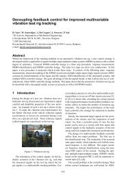
Figure 3 shows the bounded 2D <strong>acoustic</strong> problem of a car cavity filled with air (ρ = 1.225 [kg/m 3 ] and<br />
c = 340 [m/s]). The walls are rigid (¯v n =0 [m/s]) except <strong>for</strong> (i) the roof, where mixed boundary conditions are<br />
imposed ( ¯Z = 2000 [Pa.s/m]), and <strong>for</strong> (ii) the firewall, where a unit normal velocity distribution (¯v n =1 [m/s])<br />
excites the <strong>acoustic</strong> cavity. The 2D <strong>acoustic</strong> car cavity has a rather complex shaped boundary.<br />
This paper considers the following four types of models (see figure 3).<br />
• A quadratic FE model with 32982 DOFs serves as reference model. It is derived from the original FE<br />
model by subdividing each <strong>element</strong> in 36 quadratic triangular <strong>element</strong>s.<br />
• FE models with linear triangular <strong>element</strong>s are derived from the original FE model by subdividing each<br />
<strong>element</strong> in smaller <strong>element</strong>s.<br />
• WB models of 18 subdomains are considered <strong>for</strong> various values of the user defined truncation parameter<br />
T .<br />
• FE subdomains replace the small WB subdomains in the above WB models, which results in the hybrid<br />
FE-WB models. These models use a fixed truncation parameter of T = 2 <strong>for</strong> the WB submodel,<br />
whereas their FE submodels are refined gradually. Furthermore, the user defined frame impedance is<br />
fixed to ¯Z f = ρ c.<br />
4.2 Pressure spectrum analysis<br />
It is common practice to predict the pressure response at a discrete position <strong>for</strong> a broad frequency band. This<br />
paragraph considers such a pressure spectrum analysis <strong>for</strong> the position near the driver’s ear indicated by in<br />
figure 3. Figure 4 shows the prediction results obtained with<br />
• the quadratic FE model (reference),<br />
• a linear FE model with 1007 DOFs (FEM),<br />
• a WB model with T = 2 (WBM)<br />
p<br />
Z<br />
n<br />
original FE model<br />
of 449 <strong>element</strong>s<br />
WB model<br />
of 18 subdomains<br />
hybrid FE-WB model<br />
Figure 3: Problem definition and numerical models of 2D <strong>acoustic</strong> car cavity
1638 PROCEEDINGS OF ISMA2004<br />
• and a hybrid FE-WB model with T = 2 (maximum of 218 WB DOFs at 1000 [Hz]), with 303 FE<br />
DOFs and with 36 frame DOFs (HFE-WBM).<br />
The following phenomena are observed.<br />
• The FEM suffers from dispersion errors from approximately 400 [Hz] onwards. This causes the overestimation<br />
of the resonance frequencies.<br />
• The WBM suffers hardly from any dispersion error. at upper end of the However, some erroneous<br />
predictions occur <strong>for</strong> the low frequencies. At those frequencies, the WBM has not converged sufficiently<br />
with T = 2. This confirms that the WBM computational efficiency is less pronounced <strong>for</strong><br />
rather complexly shaped domains.<br />
• The HFE-WBM suffers from dispersion errors but less pronounced as the FEM. It predicts some<br />
erroneous results in the low frequency range but <strong>for</strong> different frequencies than the WBM since the WB<br />
submodel has not converged yet. The WB domain subdivision is not optimal in the sense that most<br />
WB subdomains are still irregularly shaped.<br />
The pressure spectrum analysis illustrates that the HFE-WBM is capable of providing more accurate approximations<br />
<strong>for</strong> higher frequencies than the FEM. However, with the current models, the FEM is more accurate<br />
in the low-frequency range. Another WB domain subdivision may improve the HFE-WBM accuracy. This<br />
is topic of further research.<br />
10 3 reference<br />
10 2<br />
10 1<br />
FEM<br />
|| p || in [Pa]<br />
10 3<br />
10 2<br />
10 1<br />
reference<br />
WBM<br />
10 3<br />
reference<br />
10 2<br />
10 1<br />
HFE-WBM<br />
0 200 400 600 800 1000<br />
frequency in [Hz]<br />
Figure 4: Pressure spectrum prediction <strong>for</strong> 2D <strong>acoustic</strong> car cavity
MEDIUM AND HIGH FREQUENCY TECHNIQUES 1639<br />
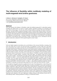
4.3 Convergence analysis<br />
In order to quantify the computational efficiency, an a posteriori error analysis is per<strong>for</strong>med at three discrete<br />
frequencies, namely at 215 [Hz], 525 [Hz] and 955 [Hz]. Figure 5 shows the corresponding convergence<br />
curves, which give the averaged relative pressure error 〈ɛ〉 as function of the model size. The averaged<br />
relative pressure error 〈ɛ〉 is defined as<br />
〈ɛ〉 =<br />
n rp<br />
∑<br />
j=1<br />
A j<br />
A<br />
‖ˆp j − ˆp ref,j ‖<br />
, (29)<br />
‖ˆp ref,j ‖<br />
where ˆp j represents the predicted pressure at response point r j , ˆp ref,j the corresponding reference solution,<br />
A j the area surrounding response point r j and A the total area. The n rp = 279 response points are indicated<br />
by + in figure 3.<br />
The convergence analysis is <strong>based</strong> on<br />
• the quadratic FE model, which provides the reference solution ˆp ref,j ,<br />
• the linear FE models (FEM),<br />
• the WB models (WBM)<br />
• and the hybrid FE-WB model with T = 2 (HFE-WBM).<br />
The convergence behaviour of the three <strong>method</strong>s is frequency dependent. The following phenomena are<br />
observed.<br />
10 0<br />
WBM<br />
215 [Hz]<br />
10 -1<br />
HFE-WBM<br />
averaged relative pressure error [-]<br />
10 -2<br />
10 0<br />
10 -1<br />
10 -2<br />
10 0<br />
WBM<br />
WBM<br />
HFE-WBM<br />
FEM<br />
525 [Hz]<br />
FEM<br />
955 [Hz]<br />
10 -1<br />
HFE-WBM<br />
FEM<br />
10 -2<br />
10 2 10 3 10 4<br />
number of DOFs<br />
Figure 5: Convergence <strong>for</strong> 2D <strong>acoustic</strong> car cavity
1640 PROCEEDINGS OF ISMA2004<br />
• At the low frequency of 215 [Hz]:<br />
– The WBM convergence curve exhibits a non-monotonic behaviour, which does not allow to draw<br />
firm conclusions on the computational efficiency of the WBM compared with the FEM.<br />
– The HFE-WBM convergence curve exhibits a more monotonic behaviour, but it converges to the<br />
wrong solutions. The WB submodel size is fixed by using T = 2. However, at this low frequency<br />
the WB part of the model is not converged yet with T = 2. Refinement of the WB submodel will<br />
restore the initial convergence rate.<br />
• At the mid frequency of 525 [Hz]:<br />
– The WBM convergence curve is less oscillatory than at 215 [Hz]. The WBM is computationally<br />
more efficient than the FEM in the sense that (i) the same accuracy is obtained with substantially<br />
smaller models and that (ii) it exhibits on average a higher convergence rate.<br />
– The HFE-WBM is computationally more efficient than the FEM in the sense that the same accuracy<br />
is obtained with smaller models.<br />
• At the high frequency of 955 [Hz]:<br />
– The WBM is computationally most efficient.<br />
– Less data is used <strong>for</strong> the FEM convergence curve, because the FEM suffers severely from dispersion<br />
errors. Consequently, large FE models are necessary to control these errors.<br />
– The computational efficiency of the HFE-WBM lies between those of the WBM and the FEM.<br />
The same accuracy as the FEM is obtained with smaller HFE-WBM models. However, the<br />
convergence rate of the HFE-WBM is comparable with the one of the FEM. This suggest that<br />
the FE submodel governs the overall accuracy.<br />
The convergence analysis illustrates that the HFE-WBM provides more accurate approximations <strong>for</strong> higher<br />
frequencies as compared to the FEM. Obviously, this improved computational efficiency at the higher frequencies<br />
is obtained without loss of geometrical flexibility, since the regions near complexly shaped boundaries<br />
can be modelled by the FEM and the interior, more regularly shaped regions by the WBM.<br />
5 Conclusions and recommendations <strong>for</strong> future research<br />
This paper considers the extension of the frequency application range of the deterministic FE <strong>method</strong>s <strong>for</strong><br />
<strong>steady</strong>-<strong>state</strong> <strong>acoustic</strong> problems. Several improvements of the FEM and several indirect Trefftz <strong>method</strong>s<br />
have been proposed in literature to achieve this. This paper focuses on the hybrid coupling of the FEM<br />
with the WBM, which is a promising alternative <strong>for</strong> the FEM. The resulting HFE-WBM benefits from the<br />
advantageous features of both <strong>method</strong>s, which are the high geometrical flexibility of the FEM and the high<br />
computational efficiency of the WBM. This paper reviews the theory on the FEM and WBM and it provides<br />
a theoretical foundation <strong>for</strong> the new HFE-WBM.<br />
A pressure spectrum analysis and a convergence analysis have been per<strong>for</strong>med on a numerical validation<br />
example of a 2D <strong>acoustic</strong> car cavity. The results of these analyses illustrate that the HFE-WBM is capable<br />
to provide more accurate results at higher frequencies than the FEM. Furthermore, the HFE-WBM exhibits<br />
more geometrical flexibility than the WBM.
MEDIUM AND HIGH FREQUENCY TECHNIQUES 1641<br />
The promising results <strong>for</strong>m the motivation <strong>for</strong> the further development of the HFE-WBM. Future research<br />
will focus on<br />
• the influence of the domain subdivision on the low frequency accuracy, especially the influence of the<br />
WB domain subdivision,<br />
• the influence of the user defined frame impedance ¯Z f<br />
• and the feasibility of a direct hybrid coupling approach, which does not involve an additional frame<br />
approximation.<br />
Acknowledgements<br />
The research work of Bas van Hal and Caroline Vanmaele is financed by scholarships of the Institute <strong>for</strong><br />
the Promotion of Innovation through Science and Technology in Flanders (IWT-Vlaanderen). Part of the<br />
presented work is per<strong>for</strong>med during the research stay of Petra Silar at K.U.Leuven in the framework of the<br />
EDSVS - European Doctorate in Sound and Vibration Studies, which is supported by the European Union<br />
through the Marie Curie Multi-Partner Training Site EC program.<br />
References<br />
[1] O.C. Zienkiewicz, R.L. Taylor, The Finite Element Method - Volume 1: Basic <strong>for</strong>mulation and linear<br />
problems, McGraw-Hill (1989).<br />
[2] O.C. Zienkiewicz, R.L. Taylor, The Finite Element Method - Volume 2: Solid and Fluid Mechanics,<br />
Dynamics and Non-Linearity, McGraw-Hill (1991).<br />
[3] F. Ihlenburg, Finite Element Analysis of Acoustic Scattering, Applied Mathematical Sciences, Vol. 132,<br />
Springer (1998).<br />
[4] I. Harari, T.J.R. Hughes Galerkin/least-squares <strong>finite</strong> <strong>element</strong> <strong>method</strong>s <strong>for</strong> the reduced <strong>wave</strong> equation<br />
with non-reflecting boundary conditions in unbounded domains, Computer <strong>method</strong>s in applied mechanics<br />
and engineering, Vol. 98 (1992), pp. 411–454.<br />
[5] I. Babu˘ska, F. Ihlenburg, E.T. Paik, S.A. Sauter, A Generalized Finite Element Method <strong>for</strong> solving the<br />
Helmholtz equation in two dimensions with minimal pollution, Computer <strong>method</strong>s in applied mechanics<br />
and engineering, Vol. 128 (1995), pp. 325–359.<br />
[6] J.M. Melenk, I. Babu˘ska, The partition of unity <strong>finite</strong> <strong>element</strong> <strong>method</strong>: Basic theory and applications,<br />
Computer <strong>method</strong>s in applied mechanics and engineering, Vol. 139 (1996), pp. 289–314.<br />
[7] Ph. Bouillard, S. Suleau, Element-Free Galerkin solutions <strong>for</strong> Helmholtz problems: <strong>for</strong>mulation and<br />
numerical assessment of the pollution effect, Computer <strong>method</strong>s in applied mechanics and engineering,<br />
Vol. 162 (1998), pp. 317–335.<br />
[8] L.P. Franca, C. Farhat, A.P. Macedo, M. Lesoinne, Residual-free bubbles <strong>for</strong> the Helmholtz equation,<br />
International Journal <strong>for</strong> Numerical Methods in Engineering, Vol. 40 (1997), pp. 4003–4009.<br />
[9] C. Farhat, I. Harari, L.P. Franca, The discontinuous enrichment <strong>method</strong>, Computer <strong>method</strong>s in applied<br />
mechanics and engineering, Vol. 190 (2001), pp. 6455–6479.<br />
[10] E. Trefftz, Ein Gegenstück zum Ritzschen Verfahren, in Proceedings of the 2 nd International Congress<br />
of Applied Mechanics, Zürich (1926), pp. 131–137.
1642 PROCEEDINGS OF ISMA2004<br />
[11] E. Kita, N. Kamiya, Trefftz <strong>method</strong>: an overview, Advances in Engineering Software, Vol. 24 (1995),<br />
pp. 3–12.<br />
[12] J. Jirousek, W. Wróblewski, T-<strong>element</strong>s: State of the Art and Future Trends, Archives of Computational<br />
Methods in Engineering – State of the art reviews, Vol. 3 (1996), pp. 323–434.<br />
[13] S. Finnveden, Exact spectral <strong>finite</strong> <strong>element</strong> analysis of stationary vibrations in a rail way car structure,<br />
Acta Acustica, Vol. 2 (1994), pp. 461–482.<br />
[14] U. Orrenius, S. Finnveden, Calculation of <strong>wave</strong> propagation in rib-stiffened plate structures, Journal<br />
of Sound and Vibration, Vol. 198 (1996), pp. 203–224.<br />
[15] M. Stojek, Finite T-<strong>element</strong>s <strong>for</strong> the Poisson and Helholtz equations, Ph.D. thesis, École Polytechnique<br />
Fédéral de Lausanne, Lausanne (1996).<br />
[16] J.A. Teixeira de Freitas, <strong>Hybrid</strong>-Trefftz displacement and stress <strong>element</strong>s <strong>for</strong> elastodynamic analysis<br />
in the frequency domain, Computer Assisted Mechanics and Engineering Sciences, Vol. 4 (1997),<br />
pp. 345–368.<br />
[17] W. Desmet, A <strong>wave</strong> <strong>based</strong> prediction technique <strong>for</strong> coupled vibro-<strong>acoustic</strong> analysis, Ph.D. thesis,<br />
Katholieke Universiteit Leuven, Leuven (1998).<br />
[18] L. Arnaud, P. Ladevèze, C. Blanzé, First application of the variational theory of complex rays to <strong>for</strong>ced<br />
vibrations of plates in the medium-frequency range, in B.H.V. Topping, editor, Computational Mechanics:<br />
Techniques and Developments (2000), pp. 121–128.<br />
[19] W. Desmet, Mid-frequency vibro-<strong>acoustic</strong> modelling: challenges and potential solutions, in Proceedings<br />
ISMA2002 – Noise and Vibration Engineering, Leuven (2002), pp. 835–862.<br />
[20] B. van Hal, W. Desmet, D. Vandepitte, P. Sas, A Coupled Finite Element – Wave Based Method <strong>for</strong><br />
the Steady-State Dynamic Analysis of Acoustic Systems, Journal of Computational Acoustics, Vol. 11<br />
(2003), pp. 285–303.<br />
[21] B. van Hal, W. Desmet, D. Vandepitte, P. Sas, <strong>Hybrid</strong> Finite Element – Wave Based Method <strong>for</strong> Acoustic<br />
Problems, Computer Assisted Mechanics and Engineering Sciences, Vol. 10 (2003), pp. 479–494.<br />
[22] W. Desmet, B. van Hal, P. Sas, D. Vandepitte, A computational efficient prediction technique <strong>for</strong> the<br />
<strong>steady</strong>-<strong>state</strong> dynamic analysis of coupled vibro-<strong>acoustic</strong> systems, Advances in Engineering Software,<br />
Vol. 33 (2002), pp. 527–540.<br />
[23] B. Pluymers, W. Desmet, B. van Hal, D. Vandepitte, P. Sas, An object-oriented implementation scheme<br />
<strong>for</strong> an efficient <strong>wave</strong> <strong>based</strong> prediction technique <strong>for</strong> <strong>steady</strong>-<strong>state</strong> vibro-<strong>acoustic</strong> problems, in Proceedings<br />
of the Ninth International Congress on Sound and Vibration, Orlando (2002).<br />
[24] B. van Hal, A. Hepberger, H.-H. Priebsch, W. Desmet, P. Sas, High per<strong>for</strong>mance implementation and<br />
conceptual development of the <strong>wave</strong> <strong>based</strong> <strong>method</strong> <strong>for</strong> <strong>steady</strong>-<strong>state</strong> dynamic analysis of <strong>acoustic</strong> problems,<br />
in Proceedings ISMA2002 – Noise and Vibration Engineering, Leuven (2002), pp. 817–826.