emissions test report compliance test of two natural - MurCal, Inc.
emissions test report compliance test of two natural - MurCal, Inc.
emissions test report compliance test of two natural - MurCal, Inc.

You also want an ePaper? Increase the reach of your titles
YUMPU automatically turns print PDFs into web optimized ePapers that Google loves.
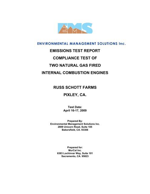
ENVIRONMENTAL MANAGEMENT SOLUTIONS <strong>Inc</strong>.<br />
EMISSIONS TEST REPORT<br />
COMPLIANCE TEST OF<br />
TWO NATURAL GAS FIRED<br />
INTERNAL COMBUSTION ENGINES<br />
RUSS SCHOTT FARMS<br />
PIXLEY, CA.<br />
Test Date:<br />
April 16-17, 2009<br />
Prepared By:<br />
Environmental Management Solutions <strong>Inc</strong>.<br />
2809 Unicorn Road, Suite 105<br />
Bakersfield, CA. 93308<br />
Prepared for:<br />
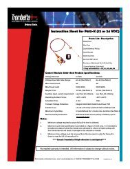
<strong>MurCal</strong> <strong>Inc</strong>.<br />
6383 Lochinvar Way, Suite 101<br />
Sacramento, CA. 95823
Environmental Management Solutions <strong>Inc</strong>.<br />
Russ Schott Farm<br />
PREFACE<br />
Environmental Management Solutions, <strong>Inc</strong>. (EMS) was contracted by <strong>MurCal</strong> <strong>Inc</strong>. to<br />
provide <strong>emissions</strong> source <strong>test</strong>ing at the exhaust stacks <strong>of</strong> <strong>two</strong> rich-burn, <strong>natural</strong> gasfired,<br />
internal combustion engines owned and operated by Russ Schott Farms. Each<br />
engine has been retr<strong>of</strong>itted with a <strong>MurCal</strong> “Emissionator” emission control system.<br />
Testing was performed to determine <strong>compliance</strong> with The San Joaquin Valley Air<br />
Pollution Control District (SJVAPCD) Rule 4702. In addition this program was designed<br />
to determine the destruction efficiency <strong>of</strong> the control system. All <strong>test</strong>ing was completed<br />
April 16 -17, 2009.<br />
The Project Manager for EMS was Mr. Steve Croghan. The <strong>test</strong>ing was performed by<br />
Mr. Jim McSweeney <strong>of</strong> TRC Environmental Corp. The representative and witness for<br />
SJVAPCD was Mr. Greg Lafore. The Project Coordinator for <strong>MurCal</strong> was Mr. Tyrone<br />
Hunter. All calculations and raw data are located in the Appendices. The following<br />
tables summarize the Compliance Test results and the applicable emission limits listed<br />
in Rule 4702 for rich burn engines used exclusively in agricultural operations.<br />
Executive Summary<br />
Engine<br />
Model<br />
Test Date<br />
NO X<br />
ppmdv<br />
NO X ppmvd<br />
@ 15% O 2<br />
CO<br />
ppmdv<br />
VOC 1<br />
CO<br />
15 % O 2 C 3 -C 6<br />
ppmvd @ ppm<br />
VOC<br />
ppm @<br />
15% O 2<br />
Cummins<br />
G855<br />
Caterpillar<br />
3406<br />
4/16-17/09 18.76 5.30 77.64 21.92 ND
Environmental Management Solutions <strong>Inc</strong>.<br />
Russ Schott Farm<br />
TABLE OF CONTENTS<br />
1.0 GENERAL INFORMATION.................................................................................. 1<br />
1.1 Name and Location <strong>of</strong> Facility 1<br />
1.2 Scope and Objectives 1<br />
1.3 Parameters and Pollutants 1<br />
1.4 Program Schedule 1<br />
1.5 Test Program Organization 2<br />
2.0 DETAILED ENGINEERING DESCRIPTION ........................................................ 3<br />
2.1 Plant and Process Description 3<br />
2.2 Sampling Locations 3<br />
3.0 INSTRUMENTATION AND EQUIPMENT DESCRIPTION................................... 4<br />
3.1 CEMS 4<br />
3.2 Calibration Gas Blending 4<br />
3.3 Oxygen 4<br />
3.4 Oxides <strong>of</strong> Nitrogen 4<br />
3.5 Carbon Monoxide 4<br />
3.6 Volatile Organic Compounds 5<br />
3.7 Data Acquisition System 5<br />
4.0 DESCRIPTION OF SAMPLING AND ANALYTICAL PROCEDURES................. 6<br />
4.1 Pre-Sampling Activities and Equipment Calibration 6<br />
4.2 Testing and Analytical Methods for Instrumental Sampling 6<br />
4.3 Engine Operational Parameters 7<br />
5.0 SUMMARY OF RESULTS ................................................................................... 8<br />
6.0 QUALITY ASSURANCE/QUALITY CONTROL................................................. 10<br />
6.1 Introduction 10<br />
6.2 Data Reduction, Validation, and Reporting 10<br />
6.3 Data Reporting 11<br />
i
Environmental Management Solutions <strong>Inc</strong>.<br />
Russ Schott Farm<br />
LIST OF TABLES<br />
Table 1 Program Schedule 1<br />
Table 2 Emission Control Summary 3<br />
Table 3 Compliance Test Matrix 7<br />
Table 4 Cummins G855 Pre-Catalyst Test Run Results 8<br />
Table 5 Cummins G855 Catalyst Outlet Test Run Results 8<br />
Table 6 Caterpillar 3406 Pre-Catalyst Test Run Results 9<br />
Table 7 Caterpillar 3406 Catalyst Outlet Test Run Results 9<br />
ii
Environmental Management Solutions <strong>Inc</strong>.<br />
Russ Schott Farm<br />
1.1 Name and Location <strong>of</strong> Facility<br />
1.0 GENERAL INFORMATION<br />
Russ Schott Farm owns and operates <strong>two</strong> rich burn, <strong>natural</strong> gas fired, internal<br />
combustion engines located in Pixley, CA. The engines are located West <strong>of</strong> Road 152,<br />
N/S <strong>of</strong> Avenue 120, E/W <strong>of</strong> Road 144.<br />
1.2 Scope and Objectives<br />
The <strong>test</strong> program was designed to determine <strong>compliance</strong> with SJVAPCD Rule 4702 and<br />
evaluate the efficiency <strong>of</strong> the <strong>MurCal</strong> emission control system. The engines were<br />
operated at a load condition representative <strong>of</strong> the manufacturer’s maximum rated<br />
capacity during all <strong>compliance</strong> <strong>test</strong> runs.<br />
Source <strong>test</strong>ing employed the use <strong>of</strong> U.S Environmental Protection Agency (EPA) Test<br />
Methods 3A, 7E, 10, 18, and 205 as described under 40 CFR, Part 51, 60, Appendix A.<br />
This source <strong>test</strong>ing program followed “The Source Test Protocol” document submitted<br />
by EMS to SJVAPCD on February 27, 2009 with no notable deviations.<br />
1.3 Parameters and Pollutants<br />
The parameters and pollutants monitored were:<br />
• Oxygen (O 2 % dry vol.);<br />
• Oxides <strong>of</strong> Nitrogen (NO X ppmdv);<br />
• Carbon Monoxide (CO ppmdv);<br />
• Volatile Organic Compounds (VOC ppm)<br />
1.4 Program Schedule<br />
Table 1 presents the schedule <strong>of</strong> the <strong>compliance</strong> and engineering source <strong>test</strong>ing at<br />
Russ Schott Farm.<br />
Table 1 Program Schedule<br />
DATE<br />
April 16, 2009<br />
April 17, 2009<br />
ACTIVITY<br />
Travel to site, set up equipment and performed <strong>test</strong> run 1 on the<br />
Cummins G855. Move equipment. Test Caterpillar 3406 <strong>test</strong>s 1-<br />
3. Demobilized.<br />
Travel to site, set up equipment, performed <strong>test</strong> runs 2-3 on the<br />
Cummins G855. Demobilized.<br />
1
Environmental Management Solutions <strong>Inc</strong>.<br />
Russ Schott Farm<br />
1.5 Test Program Organization<br />
The key representatives from the various organizations involved in the performance and<br />
evaluation <strong>of</strong> this <strong>test</strong> program are as follows:<br />
Environmental Management Solutions<br />
Mr. Steve Croghan<br />
Project Manager<br />
2809 Unicorn Rd., Suite 105<br />
Bakersfield, CA. 93308<br />
661.303.8312<br />
<strong>MurCal</strong> <strong>Inc</strong>.<br />
Mr. Tyrone Hunter<br />
Regional Sales Manager<br />
6383 Lochinvar Way, Ste.101<br />
Sacramento, CA. 95823<br />
916.682.7352<br />
Environmental Management Solutions<br />
Mr. Jim Steiner<br />
Quality Assurance<br />
1214 Wigwam Park Way, Suite 100<br />
Las Vegas, NV. 89074<br />
702.592.4333<br />
San Joaquin Valley APCD<br />
Mr. Greg Lafore<br />
Sr. Air Quality Engineer<br />
Southern Region<br />
2700 M Street, Suite 275<br />
Bakersfield, CA. 93301<br />
661.326.6500<br />
2
Environmental Management Solutions <strong>Inc</strong>.<br />
Russ Schott Farm<br />
2.1 Plant and Process Description<br />
2.0 DETAILED ENGINEERING DESCRIPTION<br />
Russ Schott Farms owns and operates <strong>two</strong> rich burn, <strong>natural</strong> gas fired, internal<br />
combustion engines located in Pixley, CA. These engines are coupled to water pumps<br />
that provide irrigation water to the farm. The engines are one Cummins 200 HP Model<br />
G855, and one Caterpillar 365 HP Model 3406. The purpose <strong>of</strong> this <strong>test</strong> was to<br />
determine <strong>compliance</strong> with SJVAPCD Rule 4702 and to demonstrate the control<br />
efficiency <strong>of</strong> the <strong>MurCal</strong> “Emissionator” Control System. This system consists <strong>of</strong> a<br />
Miratech Model VXC Non-Selective 3 way catalytic converter, a Compliance Controls<br />
Model AFR1 air/fuel ratio controller, and a Compliance Controls Model HEGO Oxygen<br />
sensor. The following table presents the destruction efficiency for the measured<br />
parameters:<br />
Table 2 Emission Control Summary<br />
Unit<br />
Oxides <strong>of</strong><br />
Nitrogen<br />
Carbon<br />
Monoxide<br />
Volatile Organic<br />
Compounds (C 3 -C 6+ )<br />
(% DE)<br />
(% DE)<br />
(% DE)<br />
Cummins<br />
G855<br />
Caterpillar<br />
3406<br />
99.35% 98.30% 100%<br />
98.97% 98.83% 100%<br />
2.2 Sampling Locations<br />
Flue gas was extracted at the engine exhaust pipe upstream <strong>of</strong> the catalytic converter<br />
and at the outlet <strong>of</strong> the catalytic converter. A single sample point was used for this <strong>test</strong><br />
program as allowed for exhaust diameters <strong>of</strong> 4 inches or less.<br />
3
Environmental Management Solutions <strong>Inc</strong>.<br />
Russ Schott Farm<br />
3.0 INSTRUMENTATION AND EQUIPMENT DESCRIPTION<br />
3.1 CEMS<br />
The gas samples from each engine exhaust sample location were extracted through a<br />
316L stainless steel probe and particulate filter assembly. The sample was then<br />
transported through a heat-traced Teflon ® line to a Universal Analyzer Model 1060<br />
sample conditioner. The sample line was maintained at a temperature <strong>of</strong> 250°F. The<br />
Model 1060 is thermo-electrically cooled and maintained at the factory set point <strong>of</strong> 3-4 o<br />
C. The sample conditioner removes the moisture from the gas stream. The sample<br />
pump then transports the dry gas samples through a length <strong>of</strong> Teflon tubing to the<br />
analyzer distribution manifold located in the lab trailer.<br />
3.2 Calibration Gas Blending<br />
An Environics 2020 Series Gas Blender was used to create the proper gas<br />
concentrations during the calibration <strong>of</strong> the CEMS instruments. The Environics Model<br />
2020 is a microprocessor-controlled device that meets or exceeds EPA Method 205<br />
specifications. This device uses 4 temperature and pressure compensated mass flow<br />
controllers to blend high purity nitrogen with high concentration gases to deliver the<br />
proper concentration <strong>of</strong> gas during calibrations. An audit <strong>of</strong> the instrument was<br />
performed before use on this project. The result <strong>of</strong> this audit is located in the<br />
Appendices <strong>of</strong> this <strong>report</strong>.<br />
3.3 Oxygen<br />
A Servomex Model 1440 O 2 analyzer was used to measure O 2 concentrations in the<br />
flue gas. The Servomex Model 1440 uses a paramagnetic detector to measure O 2<br />
percent volume on a dry basis.<br />
3.4 Oxides <strong>of</strong> Nitrogen<br />
A Teledyne-API Model 300EH was used to measure the concentration <strong>of</strong> NO X in the<br />
flue gas stream. The Model 300EH utilizes a photo-multiplier tube to detect the chemiluminescent<br />
reaction to measure NO x parts per million dry (ppmdv). A NO 2 converter<br />
check was performed during the initial calibration <strong>of</strong> the analyzer by introducing a<br />
Nitrogen Dioxide gas directly to the analyzer. The result <strong>of</strong> the check verified ≥90%<br />
NO 2 →NO conversion efficiency.<br />
3.5 Carbon Monoxide<br />
A Thermo-Fischer Corporation Model 48C was used to measure the concentration <strong>of</strong><br />
carbon monoxide in the flue gas stream. The 48C utilizes infrared gas filter correlation<br />
to measure carbon monoxide parts per million dry (ppmdv).<br />
4
Environmental Management Solutions <strong>Inc</strong>.<br />
Russ Schott Farm<br />
3.6 Volatile Organic Compounds<br />
A 316L stainless steel probe and Teflon tube were used to fill a Tedlar gas sampling<br />
bag. The exhaust gas pressure was enough to fill the bags without the use <strong>of</strong> a lung<br />
sampler and sample pump. The samples were analyzed by a SRI Gas Chromatograph<br />
utilizing a flame ionization detector (FID). The samples were analyzed for C 1 -C 6 . Only<br />
Non-Methane Hydrocarbons were <strong>report</strong>ed (C 3 -C 6 ) as methane.<br />
3.7 Data Acquisition System<br />
Output from the instrumental analyzers was directed to a Data Shuttle analog to digital<br />
converter (DAC) card and to a Standard analog strip chart recorder. The DAC and strip<br />
chart recorder is multi-channeled. Each channel is independently programmable for<br />
range and voltage input.<br />
The Data Shuttle ® was monitored via the parallel port to a laptop computer utilizing<br />
Strata ® commercial data acquisition s<strong>of</strong>tware. Data from each <strong>of</strong> the analyzers was<br />
integrated during a 60-second interval. The one-minute average readings were<br />
electronically recorded. These data were further averaged over the <strong>test</strong> period and<br />
corrected for calibration error, sample system bias, and drift using an audited computer<br />
program.<br />
5
Environmental Management Solutions <strong>Inc</strong>.<br />
Russ Schott Farm<br />
4.0 DESCRIPTION OF SAMPLING AND ANALYTICAL PROCEDURES<br />
4.1 Pre-Sampling Activities and Equipment Calibration<br />
Pre-sampling activities included equipment calibration, pre-cleaning <strong>of</strong> the sample lines,<br />
and other miscellaneous tasks. Each <strong>of</strong> these activities are described or referenced in<br />
the following subsections. Other pre-sampling activities included team meetings,<br />
equipment packing, and finalization <strong>of</strong> all details leading up to the coordinated initiation<br />
<strong>of</strong> the sampling program.<br />
EMS followed an orderly program <strong>of</strong> positive actions to prevent the failure <strong>of</strong> equipment<br />
or instruments during use. This preventative maintenance and careful calibration<br />
maximizes the readiness <strong>of</strong>, and assures the accurate measurements from field and<br />
laboratory instruments.<br />
Once equipment has gone through the cleaning and repair process it is then calibrated.<br />
Once the equipment had been calibrated, it was packed and stored to ensure the<br />
integrity <strong>of</strong> the equipment.<br />
4.2 Testing and Analytical Methods for Instrumental Sampling<br />
Sampling and analytical methods followed the source <strong>test</strong> protocol, and the methods<br />
outlined in 40 CFR, Part 60, Appendix A. The analyzers were calibrated using EPA<br />
protocol gas mixtures. The analyzers were initially calibrated directly. A system bias<br />
check was performed before and after the collection <strong>of</strong> <strong>test</strong> run data. The bias check<br />
used the mid-range gas mixture through the entire sampling system to check for line<br />
contamination and leaks.<br />
4.2.1 EPA Method 205<br />
Calibration gases were blended from a high level certified supply gases and high purity<br />
nitrogen. All quality checks and audits <strong>of</strong> the Environics 2020 Series Gas Blender were<br />
conducted per the procedures described in Method 205, 40 CFR Part 51, Appendix M.<br />
There were no modifications to this method.<br />
4.2.2 EPA Method 3A<br />
Sampling <strong>of</strong> the flue gas for the concentration <strong>of</strong> O 2 was performed according to the<br />
requirements and procedures <strong>of</strong> EPA Reference Method 3A, 40 CFR, Part 60, Appendix<br />
A.<br />
There were no modifications to this method.<br />
6
Environmental Management Solutions <strong>Inc</strong>.<br />
Russ Schott Farm<br />
4.2.3 EPA Method 7E<br />
Sampling <strong>of</strong> the flue gas for NO x was performed as outlined by the procedures in EPA<br />
Method 7E, 40 CFR, Part 60, Appendix A.<br />
There were no modifications to this method.<br />
4.2.4 EPA Method 10<br />
Sampling <strong>of</strong> the flue gas for Carbon Monoxide was performed as outlined by the<br />
procedures in EPA Method 10, 40 CFR, Part 60, Appendix A.<br />
There were no modifications to this method.<br />
4.2.6 EPA Method 18<br />
Sampling <strong>of</strong> the flue gas for Non Methane Hydrocarbons was performed as outlined by<br />
the procedures in EPA Method 18, 40 CFR, Part 60, Appendix A.<br />
There were no modifications to this method.<br />
Table 4 summarizes the <strong>test</strong>ing procedures that were used during this <strong>test</strong> program.<br />
Table 3 Compliance Test Matrix<br />
Parameters<br />
Sampling<br />
Method<br />
Number<br />
<strong>of</strong> Runs<br />
Sample<br />
Run Time<br />
Analytical<br />
Method<br />
Analytical<br />
Lab<br />
O 2 EPA 3A 3 30 minutes Instrumental EMS<br />
NO X EPA 7E 3 30 minutes Instrumental EMS<br />
CO EPA 10 3 30 minutes Instrumental EMS<br />
VOC EPA 18 3 30 minutes GC-FID TRC<br />
4.3 Engine Operational Parameters<br />
The engines were operated at a maximum load condition determined by engine and<br />
pump shaft RPM.<br />
7
Environmental Management Solutions <strong>Inc</strong>.<br />
Russ Schott Farm<br />
5.0 SUMMARY OF RESULTS<br />
EMS performed <strong>compliance</strong> Test Run 1 <strong>of</strong> the Cummins G855 on April 16, 2009. After<br />
this <strong>test</strong> run the engine was shut down due to a spark plug failure. Test Runs 2 and 3<br />
were performed on April 17, 2009 after the spark plug was replaced. All <strong>test</strong> runs<br />
demonstrated that the Cummins G855 was in <strong>compliance</strong> with Rule 4702. The <strong>test</strong>ing<br />
<strong>of</strong> the Caterpillar 3406 was performed and completed April 16, 2009. The <strong>test</strong>ing <strong>of</strong> this<br />
engine was only for determining control system efficiency as the engine had previously<br />
been <strong>test</strong>ed for <strong>compliance</strong>. Each engine was operated at a maximum <strong>of</strong> 100% <strong>of</strong> load<br />
capacity verified by RPM. Appendices A through C contain the results <strong>of</strong> the <strong>test</strong>ing.<br />
Appendix A presents the Emissions Calculations. Appendix B contains EMS’s raw field<br />
data and CEMS data package. Appendix C contains the VOC Laboratory Analysis.<br />
Appendix D contains the equipment calibration data package and gas certifications.<br />
Appendix E contains the SJVAPCD COM 2030 worksheets. The following tables<br />
present the <strong>compliance</strong> <strong>test</strong> results <strong>of</strong> each engine.<br />
Table 4 Cummins G855 Pre-Catalyst Test Run Results<br />
Test<br />
Oxygen<br />
(%dry)<br />
NO X<br />
ppmvd<br />
NO X<br />
ppm @<br />
15% O 2<br />
CO<br />
ppmvd<br />
CO ppm VOC 1<br />
@ 15% O 2 ppmv<br />
VOC<br />
ppm @<br />
15% O 2<br />
1 0.52 2755.66 797.74 4391.13 1271.20 53.38 15.45<br />
2 0.42 2832.62 815.86 4502.61 1296.85 74.76 21.54<br />
3 0.44 2837.20 818.09 4504.62 1298.89 55.92 16.12<br />
Average 0.46 2808.49 810.56 4466.12 1288.98 61.35 17.70<br />
1<br />
VOC <strong>report</strong>ed as methane (C 3 -C 6+ ). ND= Not Detected
Environmental Management Solutions <strong>Inc</strong>.<br />
Russ Schott Farm<br />
Table 6 Caterpillar 3406 Pre-Catalyst Test Run Results<br />
Test<br />
Oxygen<br />
(%dry)<br />
NO X<br />
ppmvd<br />
NO X<br />
ppm @<br />
15% O 2<br />
CO<br />
ppmvd<br />
CO ppm VOC 1<br />
@ 15% O 2 ppmv<br />
VOC<br />
ppm @<br />
15% O 2<br />
1 0.37 2433.06 699.27 2678.66 769.86 16.54 4.75<br />
2 0.35 2477.90 711.47 2762.58 793.21 18.58 5.33<br />
3 0.36 2477.97 711.79 2707.49 777.72 12.70 3.65<br />
Average 0.36 2462.98 707.51 2716.24 780.26 15.94 4.58<br />
1<br />
VOC <strong>report</strong>ed as methane (C 3 -C 6+ ). ND= Not Detected
Environmental Management Solutions <strong>Inc</strong>.<br />
Russ Schott Farm<br />
6.0 QUALITY ASSURANCE/QUALITY CONTROL<br />
6.1 Introduction<br />
Quality Assurance/Quality Control (QA/QC) protocols followed during this program were<br />
based on the procedures <strong>of</strong> the methods employed. Results <strong>of</strong> the QA/QC activities<br />
employed during this program are provided in this section.<br />
All calculations are done using standardized EPA equations as part <strong>of</strong> EMS's ongoing<br />
quality control for data reduction and <strong>report</strong>ing. EMS routinely reduces field data on a<br />
daily basis using a personal computer with s<strong>of</strong>tware containing the EPA equations.<br />
6.1.1 Calibration Gases<br />
All calibration gases used to conduct instrument calibrations on EMS’s continuous<br />
oxygen (O 2 ), nitrogen oxide (NO X ), and carbon monoxide (CO) emission monitors were<br />
prepared in accordance with EPA Protocol 1, or are traceable to the National Institute <strong>of</strong><br />
Standards and Technology (NIST).<br />
6.1.2 Instrument Calibrations<br />
EMS’s oxygen instrument calibrations met the performance criteria defined in 40 CFR<br />
60 Appendix A, Method 3A. The NO X instrument calibrations met the performance<br />
criteria defined in 40 CFR 60 Appendix A, Method 7E and the carbon monoxide<br />
instrument calibrations met the performance criteria defined in 40 CFR 60 Appendix A,<br />
Method 10.<br />
6.1.3 Equipment Leak Checks<br />
Prior to sampling the sampling system was leak checked under 15” Hg. for 2 minutes.<br />
During the course <strong>of</strong> each <strong>test</strong> run, a leak check was conducted before and after<br />
sampling. Final leak checks were performed to ensure that no leaks developed in the<br />
system during the course <strong>of</strong> the <strong>test</strong> run.<br />
6.2 Data Reduction, Validation, and Reporting<br />
Specific QC measures were used to ensure the generation <strong>of</strong> reliable data from<br />
sampling and analysis activities. The proper collection and organization <strong>of</strong> accurate<br />
information, followed by clear and concise <strong>report</strong>ing <strong>of</strong> the data, was the primary goal in<br />
this program.<br />
10
Environmental Management Solutions <strong>Inc</strong>.<br />
Russ Schott Farm<br />
6.2.1 Data Validation<br />
EMS supervisory and QC personnel used validation methods and criteria appropriate to<br />
the type <strong>of</strong> data and the purpose <strong>of</strong> the measurement. Records <strong>of</strong> all data were<br />
maintained, including that judged to be an "outlying" or spurious value. The persons<br />
validating the data have sufficient knowledge <strong>of</strong> the technical work to identify<br />
questionable values.<br />
The field sampling data was validated by the Field Team Leader and the QC<br />
Coordinator. This decision was based on their review <strong>of</strong> the adherence to the approved<br />
sampling protocol and written sample collection procedures.<br />
The following criteria were used to evaluate the field sampling data:<br />
• Use <strong>of</strong> approved <strong>test</strong> procedures;<br />
• Proper operation <strong>of</strong> the process being <strong>test</strong>ed;<br />
• Use <strong>of</strong> properly operating and calibrated equipment;<br />
• Leak checks conducted before and after <strong>test</strong>s;<br />
The criteria listed below were used to evaluate the analytical data:<br />
• Use <strong>of</strong> approved analytical procedures;<br />
• Use <strong>of</strong> properly operating and calibrated instrumentation;<br />
• Acceptable results from analyses <strong>of</strong> QC samples.<br />
6.3 Data Reporting<br />
All data was <strong>report</strong>ed in standard units depending on the measurement and the ultimate<br />
use <strong>of</strong> the data.<br />
11