Appendix C: Entity Relationship Diagram for Electronic Resource
Appendix C: Entity Relationship Diagram for Electronic Resource
Appendix C: Entity Relationship Diagram for Electronic Resource

You also want an ePaper? Increase the reach of your titles
YUMPU automatically turns print PDFs into web optimized ePapers that Google loves.
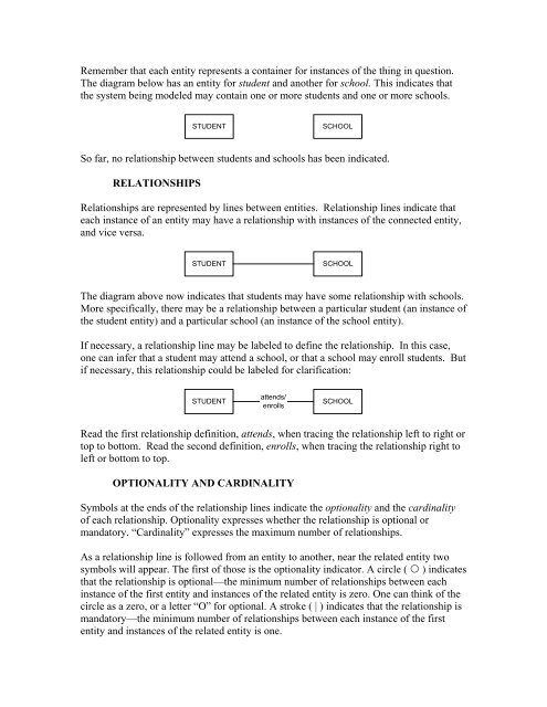
Remember that each entity represents a container <strong>for</strong> instances of the thing in question.<br />
The diagram below has an entity <strong>for</strong> student and another <strong>for</strong> school. This indicates that<br />
the system being modeled may contain one or more students and one or more schools.<br />
STUDENT<br />
SCHOOL<br />
So far, no relationship between students and schools has been indicated.<br />
RELATIONSHIPS<br />
<strong>Relationship</strong>s are represented by lines between entities. <strong>Relationship</strong> lines indicate that<br />
each instance of an entity may have a relationship with instances of the connected entity,<br />
and vice versa.<br />
STUDENT<br />
SCHOOL<br />
The diagram above now indicates that students may have some relationship with schools.<br />
More specifically, there may be a relationship between a particular student (an instance of<br />
the student entity) and a particular school (an instance of the school entity).<br />
If necessary, a relationship line may be labeled to define the relationship. In this case,<br />
one can infer that a student may attend a school, or that a school may enroll students. But<br />
if necessary, this relationship could be labeled <strong>for</strong> clarification:<br />
STUDENT<br />
attends/<br />
enrolls<br />
SCHOOL<br />
Read the first relationship definition, attends, when tracing the relationship left to right or<br />
top to bottom. Read the second definition, enrolls, when tracing the relationship right to<br />
left or bottom to top.<br />
OPTIONALITY AND CARDINALITY<br />
Symbols at the ends of the relationship lines indicate the optionality and the cardinality<br />
of each relationship. Optionality expresses whether the relationship is optional or<br />
mandatory. “Cardinality” expresses the maximum number of relationships.<br />
As a relationship line is followed from an entity to another, near the related entity two<br />
symbols will appear. The first of those is the optionality indicator. A circle ( ◦ ) indicates<br />
that the relationship is optional—the minimum number of relationships between each<br />
instance of the first entity and instances of the related entity is zero. One can think of the<br />
circle as a zero, or a letter “O” <strong>for</strong> optional. A stroke ( | ) indicates that the relationship is<br />
mandatory—the minimum number of relationships between each instance of the first<br />
entity and instances of the related entity is one.