Download the SC Series Product Manual - SK Watermakers
Download the SC Series Product Manual - SK Watermakers
Download the SC Series Product Manual - SK Watermakers

Create successful ePaper yourself
Turn your PDF publications into a flip-book with our unique Google optimized e-Paper software.
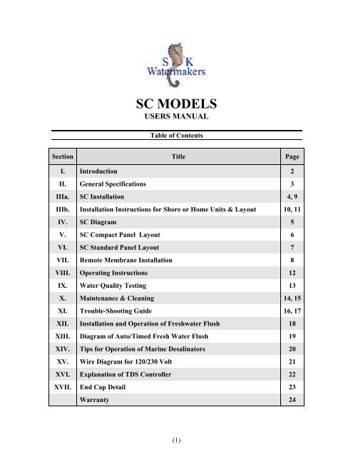
<strong>SC</strong> MODELS<br />
USERS MANUAL<br />
Table of Contents<br />
Section Title Page<br />
I. Introduction 2<br />
II. General Specifications 3<br />
IIIa. <strong>SC</strong> Installation 4, 9<br />
IIIb. Installation Instructions for Shore or Home Units & Layout 10, 11<br />
IV. <strong>SC</strong> Diagram 5<br />
V. <strong>SC</strong> Compact Panel Layout 6<br />
VI. <strong>SC</strong> Standard Panel Layout 7<br />
VII. Remote Membrane Installation 8<br />
VIII. Operating Instructions 12<br />
IX. Water Quality Testing 13<br />
X. Maintenance & Cleaning 14, 15<br />
XI. Trouble-Shooting Guide 16, 17<br />
XII. Installation and Operation of Freshwater Flush 18<br />
XIII. Diagram of Auto/Timed Fresh Water Flush 19<br />
XIV. Tips for Operation of Marine Desalinators 20<br />
XV. Wire Diagram for 120/230 Volt 21<br />
XVI. Explanation of TDS Controller 22<br />
XVII. End Cap Detail 23<br />
Warranty 24<br />
(1)
I. <strong>SK</strong> <strong>Watermakers</strong> Introduction<br />
CONGRATULATIONS, YOU HAVE JUST PURCHASED THE MOST TROUBLE-<br />
FREE, ECONOMICAL MARINE DESALINATOR AVAILABLE!!!<br />
All of our units are manufactured using <strong>the</strong> highest quality components<br />
and utilizing <strong>the</strong> latest technologies available in <strong>the</strong> industry today. SL's innovative<br />
engineering has changed <strong>the</strong> conception of marine desalinators from an expensive,<br />
maintenance prone product of choice, to an affordable and reliable necessity for all<br />
types of watercraft.<br />
We understand <strong>the</strong> importance of each and every watermaker. We manufacture<br />
and design al of our units to be simple, reliable and easy to maintain. We currently<br />
have desalinators operating in extreme conditions form <strong>the</strong> freezing arctic waters of<br />
Antarctica to <strong>the</strong> warm humid climates of <strong>the</strong> Amazon.<br />
<strong>SK</strong> <strong>Watermakers</strong> line of Marine Desalinators are reliable and easy to install but<br />
<strong>the</strong> greatest advantage of purchasing a unit from us is affordability.<br />
(2)
II. General <strong>Product</strong> Specifications<br />
DE<strong>SC</strong>RIPTION<br />
Membrane Housing<br />
Membranes<br />
Fiberglass/aluminum (Lifetime Warranty)<br />
Thin composite R.O. membranes<br />
TEST CONDITIONS<br />
Temperature 78° F (25° C)<br />
Operating Pressure<br />
800 PSI. 900 PSI Max<br />
Feed Water Quality<br />
32,000 PPM Total Dissolved Solids<br />
(32.0K mg/L)<br />
Salt Rejection Performance<br />
99.2% Rejection NaC1 (Typical)<br />
AMPERAGE<br />
HC/<strong>SC</strong> 200-1500 115v @ 28-30 amps 230v @14-16 amps<br />
DB/HC/<strong>SC</strong> 200-600 115v @ 15 amps 230v @ 8.0 amps<br />
DB/HC/<strong>SC</strong> 600 115v @ 20 amps 230v @ 11.0 amps<br />
DC 150 22 amps (available in 24v )<br />
Note: (Larger units will vary with capacity)<br />
WATER PRODUCTION CAPABILITIES<br />
Model GPD GPH LPH<br />
<strong>SC</strong> 200 200 6 – 10 23 - 38<br />
<strong>SC</strong> 400 400 15 – 18 57 – 69<br />
<strong>SC</strong> 500 500 16 – 21 69 – 84<br />
<strong>SC</strong> 600 600 22 – 26 84 – 99<br />
<strong>SC</strong> 800 800 30 – 36 100 – 136<br />
<strong>SC</strong> 1000 1000 38 – 44 144 – 167<br />
<strong>SC</strong> 1200 1200 46 – 52 174 – 197<br />
<strong>SC</strong> 1500 1500 60 – 65 227 – 246<br />
<strong>SC</strong> 2000 2000 84 - 120 318 - 454<br />
(3)
III-a. Installation Instructions for <strong>SC</strong> Self-Contained Units<br />
Select a seawater supply<br />
Smaller units (600 GPD or under can share a thru hull with saltwater washdown or toliet<br />
pickups, but if one is not available, you will have to install a new thru hull and seacock.<br />
3/4" I.D. The thru hull must be positioned as close to <strong>the</strong> bottom center of <strong>the</strong> boat as<br />
possible. Make sure <strong>the</strong>re is nothing in <strong>the</strong> slip stream in front of <strong>the</strong> intake, or if in a<br />
sailboat, <strong>the</strong> thru hull is as low as possible so that <strong>the</strong> thru hull will not be above <strong>the</strong><br />
waterline at a large heel angle. It is advisable to install an intake strainer at this time. It<br />
would also be advantageous to keep <strong>the</strong> intake ahead of <strong>the</strong> prop wash. (Air bubbles or<br />
negative pressure are a high pressure pump's greatest enemy!!!)<br />
Select a location for <strong>the</strong> prefilter pump<br />
Locate <strong>the</strong> prefilter pump below <strong>the</strong> waterline, in a fairly dry location and as close to <strong>the</strong><br />
seacock as space permits.<br />
Select an area for <strong>the</strong> RO unit<br />
The RO unit can be above or below <strong>the</strong> waterline. If located more that 25 feet away from<br />
<strong>the</strong> prefilter pump, go to <strong>the</strong> next size hose.<br />
Select ano<strong>the</strong>r 1/2" thru hull for <strong>the</strong> brine overboard dump<br />
It should be located above <strong>the</strong> waterline. Location is not critical and you may share an air<br />
conditioning drain if installed properly<br />
Seacock/Prefilter connection<br />
Connect <strong>the</strong> seacock to prefilter with a 3/4" suction hose. Use clear braid hose furnished.<br />
Connect <strong>the</strong> output from <strong>the</strong> prefilter to <strong>the</strong> RO unit with a 3/4" minimum hose.<br />
(reinforced beverage is a good choice, supplied with most units)<br />
NOTE: INTAKE AND REJECT WATER FITTINGS ARE BOTH 3/4" ON 1500<br />
GALLON PER DAY UNITS<br />
(4)
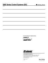
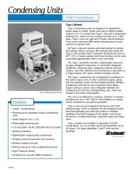
IV. Hydraulic Diagram for Self-Contained<br />
High Pressure Hose-3/8<br />
Low Pressure Seawater Hose-3/4<br />
<strong>Product</strong> Water Hose (Fresh)-3/8<br />
Concentrated Brine Overboard Hose-1/2<br />
(5)
WHITE<br />
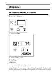
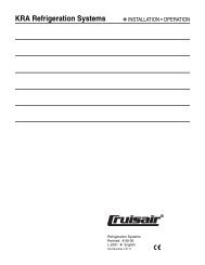
V. <strong>SC</strong> Compact Panel Layout (Rear)<br />
High pressure<br />
prefilter gauge<br />
Low pressure<br />
prefilter gauge<br />
High pressure<br />
regulator<br />
Electrical panel<br />
3-way<br />
Divert V a lve<br />
High Press. Tee to<br />
Regulator Valve and<br />
Relief Valve<br />
REAR OF <strong>SC</strong>-COMPACT<br />
PANEL REV.-6-05<br />
AIR SEPARATOR<br />
TO HIGH PRESSURE<br />
PUMP<br />
<strong>Product</strong> water<br />
flow Gauge<br />
REJECT BRINE<br />
FLOW GAUGE<br />
3/8” hose barb<br />
from membranes<br />
SALINITY<br />
PROBE<br />
To Sample Barb<br />
3-way Sample-<br />
Divert V a lve<br />
WHITE<br />
WHITE<br />
gauge port<br />
3/8" Hose Barb<br />
to Tank<br />
to freshwaer flush<br />
SEA WATER INTAKE<br />
FROM PREFILTER<br />
TO OVERBOARD PORT<br />
NORMAL OPERATION SHOWN<br />
DOTTED LINES INDICATE PICKLE<br />
OR CLEAN POSITION.<br />
High Pressure Hose<br />
from Membrane<br />
PORT# 1<br />
PORT # 2<br />
[IN BACK]<br />
FROM<br />
RAW WATER INTAKE<br />
PORT # 3<br />
CHECK VALVE<br />
restrictor at this<br />
point<br />
3/4” HOSE<br />
CHECK VALVE<br />
SAMPLE PORT TANK PORT<br />
F.WF. FLUSH PORT<br />
SEAWATER FROM<br />
PREFILTERS<br />
CLEAN OR PICKLE<br />
PORTS<br />
VALVE PANEL<br />
TO OVERBOARD PORT<br />
(6)
WHITE<br />
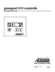
VI. <strong>SC</strong> Sta nd a rd Pa ne l La yo ut (re a r)<br />
Low pressure<br />
prefilter gauge<br />
To Sample Barb<br />
3/8" Hose Barb<br />
to Tank<br />
gauge port<br />
to freshwaer flush<br />
SALINITY<br />
PROBE<br />
<strong>Product</strong> water<br />
flow Gauge<br />
tee<br />
High pressure<br />
relief<br />
AIR SEPARATOR<br />
TO HIGH PRESSURE<br />
PUMP<br />
SEA WATER INTAKE<br />
FROM PREFILTER<br />
WHITE<br />
To over board<br />
port<br />
REJECT BRINE<br />
FLOW GAUGE<br />
3-way Sample-<br />
Divert V a lve<br />
3/8” hose barb<br />
from membranes<br />
REAR OF <strong>SC</strong>- STANDARD<br />
PANEL REV.-6-05<br />
CHECK VALVE<br />
TANK PORT<br />
SAMPLE PORT<br />
F.WF. FLUSH PORT<br />
HOSE TERMINATION<br />
AND OPERATING VALVES<br />
LOCATED ON LEFT SIDE OF UNIT<br />
SEAWATER FROM<br />
PREFILTERS<br />
CLEAN OR PICKLE<br />
PORTS<br />
TO OVERBOARD PORT<br />
NORMAL OPERATION SHOWN<br />
DOTTED LINES INDICATE PICKLE<br />
OR CLEAN POSITION.<br />
CHECK VALVE<br />
Electrical panel<br />
PORT# 1<br />
3-way<br />
Divert V a lve<br />
PORT # 2<br />
[IN BACK]<br />
PORT#3<br />
restric tor at this<br />
point<br />
High Press. Tee to<br />
Regulator Valve and<br />
Relief Valve<br />
High Pressure Hose<br />
from Membrane<br />
gauge port<br />
3/4” HOSE<br />
(7)
VII. Remote Membrane Installation<br />
Vibration Dampeners<br />
Wall Mount Membrane [s]<br />
Remove <strong>the</strong>se screws<br />
To Brine<br />
Inlet<br />
To Brine<br />
Outlet<br />
remove top<br />
screws<br />
To Open Front Panel<br />
for Service<br />
Do Not Remove Bottom Screws<br />
Supplement For Compact <strong>SC</strong> <strong>Manual</strong><br />
with Remote Membrane (s)<br />
(8)
III-a. Installation Instructions of <strong>SC</strong> Self-Contained Units (cont.)<br />
Connect <strong>the</strong> freshwater to <strong>the</strong> top of <strong>the</strong> tank with 3/8" soft tubing, <strong>the</strong>re should not be a<br />
shut off in this line because a stoppage of <strong>the</strong> product water will damage <strong>the</strong> unit or burst<br />
a hole. It should be run high enough above <strong>the</strong> tank so that any tank water will not<br />
siphon back to <strong>the</strong> RO unit.<br />
Wiring<br />
Run stranded wire to junction box from breaker panel. Use #12 for 200 – 600 GPD units<br />
and #10 for 1000 – 1500 GPD units. Use <strong>the</strong> next size gauge wire over 30 ft. The wire<br />
should be fused at 20 amps for #12 and 30 amps for #10 wire. (#14 wire may be used<br />
with 200 – 800 GPD @ 220 Volt units. Fuse at 15 amps) #12 for 1000 – 1500 GPD @<br />
220 Volt Units.<br />
Initial Start-Up<br />
Fill prefilter with clean saltwater, back off <strong>the</strong> high pressure all <strong>the</strong> way counterclockwise,<br />
press start switch and observe <strong>the</strong> clear braid hose for water flow. The water<br />
should start flowing within a minute. If no water is moving in <strong>the</strong> system, check for an<br />
air leak in <strong>the</strong> low pressure hose fittings (with a prefilter pump this is generally not a<br />
problem). When, after a couple of minutes, <strong>the</strong> water is flowing clear with no bubbles<br />
observed, slowly turn <strong>the</strong> high pressure valve clockwise to 800 PSI. The adjustable<br />
automatic regulator has been preset to approximately 800 PSI at <strong>the</strong> factory. We suggest<br />
you do not increase this for long life of your system, but it will operate up to 900 PSI<br />
without a problem. Status Lights: In normal operation after starting, <strong>the</strong> yellow led in<br />
<strong>the</strong> center of <strong>the</strong> logo will come on until <strong>the</strong> TDS (total dissolved solids) drops below <strong>the</strong><br />
set point on <strong>the</strong> TDS controller. This is preset at <strong>the</strong> factory for approx. 700 PPM (parts<br />
per million), (<strong>the</strong> suggested, max by <strong>the</strong> World Health Organization is 800 PPM). The<br />
product water can also be manually diverted with <strong>the</strong> sample valve At this time water<br />
will be rejected to <strong>the</strong> overboard automatically, although <strong>the</strong> sample valve and flow<br />
gauge will be operational at all times if needed for test purposes. After <strong>the</strong><br />
aforementioned delay, water will be diverted to tank and <strong>the</strong>: <strong>Product</strong> water to tank<br />
green led light will come on. Now <strong>the</strong> RO will be in normal operational mode. Be sure<br />
to turn <strong>the</strong> sample valve to sample and let <strong>the</strong> product water run overboard for 1 hour to<br />
rinse out any preservative. This only has to be done when <strong>the</strong> unit has been pickled, <strong>the</strong>n<br />
turn sample valve handle to TANK and enjoy a drink of pure water.<br />
(9)
III-b. Installation Instructions for Shore or Home Units<br />
The primary concerns with installation of shore based units are problems with feedwater.<br />
The most universally used and desired intake source would be from a well. A well will<br />
usually filter out most of <strong>the</strong> large matter. The passage of <strong>the</strong> sea water through sand<br />
rock does a remarkably good job as a filter. One of <strong>the</strong> disadvantages of a well is <strong>the</strong><br />
possibility of contamination by a large amount of iron, maganese or calcium, but in<br />
general, it is <strong>the</strong> preferred intake. Ano<strong>the</strong>r option would be group of 3 or 4 well points<br />
set at <strong>the</strong> beach line. (<strong>the</strong> amount of tide would have to be considered)<br />
The sea itself can also be used if is not drawn from a dirty or oily harbor. A large strainer<br />
of some sort (a long piece of .030 PVC well screen would be a good choice). Advise<br />
from professional in <strong>the</strong> well business would be advisable.<br />
After <strong>the</strong> feedwater source is decided on and installed, it should be manually primed and<br />
tested for leaks and air intrusion. The feedwater pressure should be between 25 and 35<br />
PSI when <strong>the</strong> prefilters are fresh. An adjustable relief is provided to install in your feed<br />
line.<br />
When <strong>the</strong> RO is first turned on it should be run at low pressure to check your equipment<br />
for leaks and to remove trapped air.<br />
Operation of Fully Automatic Shore Based Units<br />
CAUTION!!! BE AWARE THAT THE PUMPS MAY START AUTOMATICALLY.<br />
KEEP YOUR HAND FREE AND ELECTRIC BOXES SHUT WHEN OPERATING.<br />
Set time clock to desired start time and desired stop time with metal pointers supplied<br />
with <strong>the</strong> time clock. Example: 8:00AM start, 6:PM stop = 10 hours of operation.<br />
The first start-up after installation should be done manually. Turn <strong>the</strong> high pressure<br />
control valve all <strong>the</strong> way counterclockwise (low pressure). Turn <strong>the</strong> auto-off-manual<br />
selector switch on <strong>the</strong> control panel to <strong>the</strong> right (manual) position and press <strong>the</strong> start<br />
switch. You may not hear anything right away, but <strong>the</strong> feedwater pump should turn on at<br />
this time. There is an adjustable time delay relay that will turn <strong>the</strong> high pressure pump on<br />
after 8 minutes. At this time <strong>the</strong> electrically operated high pressure bypass valve will<br />
close, you will <strong>the</strong>n be able to adjust <strong>the</strong> high pressure control valve clockwise (to <strong>the</strong><br />
right) and raise <strong>the</strong> pressure to 800 PSI. Then manually divert <strong>the</strong> product water for<br />
about 1/2 hour to clean <strong>the</strong> preservative from <strong>the</strong> RO unit. If after 15 minutes <strong>the</strong> unit is<br />
producing more product water that is stated in your manual it would be wise to turn your<br />
product water output is close to its rated output.<br />
The high pressure is now set for both types of operation. Do not turn <strong>the</strong> high pressure<br />
control valve up or down. At this time turn <strong>the</strong> RO unit off and turn <strong>the</strong> selector switch to<br />
<strong>the</strong> left t "AUTO", manual turn <strong>the</strong> switch lever on <strong>the</strong> time clock to "ON". The<br />
feedwater pressure gauge should read over 20 lbs., 8 minutes later <strong>the</strong> main pressure<br />
pump will energize and ramp up to <strong>the</strong> preset pressure. The unit is now ready for service.<br />
(10)
Wall Mount Membrane [s]<br />
(11)
VIII. Operating Instructions<br />
Normal Startup<br />
• Turn high-pressure control valve counterclockwise to fully open position<br />
• Turn selector switch to <strong>Manual</strong> position and press start button firmly and release<br />
observing normal operation<br />
• If autostart ramp up or inverter is furnished, wait at least 1 minute <strong>the</strong>n slowly turn<br />
high-pressure control valve clockwise until pressure reaches 700 PSI. (in seawater), or<br />
until product water output reaches designed output.<br />
• When using Auto start you may leave pressure set without adjusting on every start up.<br />
• Check for leaks. Make sure water is flowing<br />
• If water is not flowing after 1 minute stop here, shut down <strong>the</strong> system and<br />
TROUBLE-SHOOT<br />
Automatic Soft Start Operation<br />
• Start unit in maual and adjust <strong>the</strong> pressure as described above.<br />
• Turn unit off by pressing <strong>the</strong> stop button. DO NOT adjust <strong>the</strong> pressure control knob.<br />
• Adjust time clock to desired hours of operation.<br />
• Turn selector switch to AUTO.<br />
• When in auto, <strong>the</strong> unit will not start until <strong>the</strong> time clock switch trips. After <strong>the</strong> switch<br />
trips to "ON" it will take 10-12 minutes to start main pump and produce water.<br />
• This unit is equipped with Soft Start system and controlled by a logic controller and<br />
for proper operation do not rapidly switch to different positions.<br />
<strong>Manual</strong> Water Quality Check<br />
• Let system run for 30 minutes<br />
• Sample water and use <strong>the</strong> handheld salinity provided to test water quality.<br />
• If reading is under 800 you may divert product to <strong>the</strong> tank.<br />
Operation in Brackish or Fresh Water<br />
• Seawater normally has about 32000 – 35000 parts per million of salt and <strong>the</strong> normal<br />
operating pressure should be at 800 - 850 PSI. However, as <strong>the</strong> salinity drops in brackish<br />
water, less pressure will be required for normal production. Do no exceed your unit's<br />
rated capacity. Use your flow gauge to determine operating pressure. For instance,<br />
totally fresh & brackish water will require approximately only 100 - 3000 PSI for rated<br />
production. Water in higher salinity areas such as <strong>the</strong> Middle East will have to operate at<br />
higher pressure (950 PSI) to achieve drinkable water and high production.<br />
The system is filled with preservative solution. Salinity (TDS) will improve after a short<br />
period of operation. When in operation it is advisable to start up with no pressure for a<br />
minute or two. When stopping <strong>the</strong> RO unit, <strong>the</strong> pressure should be turned down first.<br />
The above steps are not necessary, but will help increase <strong>the</strong> life of <strong>the</strong> unit.<br />
(12)
IX. Water Quality Testing<br />
The water quality produced by <strong>the</strong> RO unit upon starting will be low due to <strong>the</strong> normal<br />
osmotic pressure (salt tends to diffuse into fresh sea level). Under normal everyday use<br />
drinkable water would become available in a very short time (usually under a minute). If<br />
<strong>the</strong> unit sits without use for an abnormal period, <strong>the</strong> time required to produce acceptable<br />
water will increase.<br />
Low Water Quality Symptoms Causes<br />
• Time between use (every day use would be best)<br />
• Temperature (hot climates and engine rooms tend to increase<br />
bacterial activity)<br />
• Seawater quality<br />
• Salinity<br />
Low Water Quality Symptoms Reduction<br />
• Every day use<br />
• Locate <strong>the</strong> membrane in a cooler area<br />
• Fresh or permeate water flush<br />
• Preserving (pickling <strong>the</strong> membrane)<br />
Depending on <strong>the</strong> model you purchased, your unit will be provided with a electronic<br />
tester (handheld or built in). The built in models will read directly in T.D.S. (total<br />
dissolved solids) which will be salt content in parts per million. The hand held meter will<br />
also read directly in T.D.S.<br />
The world health organization recommends approximately 800 PPM as a limit, but<br />
if your unit has increased to 700 or higher, we recommend you clean or replace your<br />
membrane. Also for an accurate reading, let <strong>the</strong> RO unit run for 10-15 minutes<br />
before sampling.<br />
(13)
X. Maintenance and Cleaning<br />
Short Duration Shut Down Procedure-(less than 2 weeks)<br />
If you have a freshwater flush with your system see section on fresh water flush<br />
operation instead of this section<br />
• Connect a 3/8" hose to sample port<br />
• Stick <strong>the</strong> o<strong>the</strong>r end of <strong>the</strong> hose in a 5 gallon bucket<br />
• Turn on RO unit<br />
• Turn sample valve to sample position and fill bucket with RO product water<br />
• Stop RO unit<br />
• Connect 3/4" hose to clean/flush port on pickling valves<br />
• Stick <strong>the</strong> o<strong>the</strong>r end of <strong>the</strong> 3/4" hose into 5 gallon bucket of water<br />
• Turn high-pressure control valve counter-clockwise to fully open position<br />
• Turn <strong>the</strong> 3/4" 3-way valve handle toward clean/flush port<br />
• Turn RO on<br />
• Run system until almost all of <strong>the</strong> water has been sucked out of <strong>the</strong> 5 gallon bucket<br />
• Shut system off!!<br />
WARNING!!!<br />
DO NOT LET THE PUMP SUCK AIR-LEAVE SOME WATER IN BUCKET<br />
Do not use water from on board tanks. Chlorine may have been used in <strong>the</strong> tanks.<br />
Chlorine will permanently damage <strong>the</strong> RO membranes.<br />
Long Duration Shut Down Procedure - (more than 2 weeks)<br />
1.) Collect (2) 5 gallon containers of RO water if unit does not have a flush, only (1) is<br />
needed if it has a flush. This water can also be pure fresh water with no chlorine or<br />
ozone.<br />
2.) Turn high pressure control all <strong>the</strong> way counterclockwise (lowest pressure) and place<br />
sample valve in sample position and flush for 10 minutes if unit has a flush.<br />
3.) If unit does not have a flush system: (a) turn intake valve on left to pickling position.<br />
(no. 2) Leave valve on right in normal overboard position. (b) place short hoses on<br />
pickling valves long enough to reach bottom of 5 gallon container. Place 3/4" or left hose<br />
in <strong>the</strong> container, turn RO on until water is almost empty (do not run dry), this will flush<br />
most of <strong>the</strong> seawater from <strong>the</strong> system.<br />
4.) Now place <strong>the</strong> right-hand valve in <strong>the</strong> pickling position, both valves should have <strong>the</strong><br />
arrow pointing towards <strong>the</strong> center. (see diagram on P.14) Pour <strong>the</strong> container of pickling<br />
material in <strong>the</strong> 5 gallon bucket of water previously made in step 1. Make sure high<br />
pressure valve is turned all <strong>the</strong> way down and start RO, <strong>the</strong> pickling solution will <strong>the</strong>n be<br />
drawn into <strong>the</strong> system and back out <strong>the</strong> reject valve to <strong>the</strong> bucket, circulating in a closed<br />
loop. Run for approximately for 30 minutes.<br />
5.) Turn valves back to <strong>the</strong> original position.<br />
(14)
X. Maintenance and Cleaning (cont.)<br />
Long Duration Shut Down Procedure - (more than 2 weeks) - (cont.)<br />
6.) Stop RO unit<br />
7.) When resuming normal operation turn sample valve to sample position.<br />
8.) Start system and let it run for 30 minutes<br />
9.) Check product water with <strong>the</strong> salinity meter provided. If within operation limits you<br />
can now send product water back to tank<br />
Pump Maintenance<br />
Change pump seals on Cat Pumps after 2000 hours of use, or when leakage is<br />
encountered. Change <strong>the</strong> pump oil every 500 hours after initial 50 hour oil change.<br />
Prefilters<br />
Observe prefilter gauge pressure. This will give you a good indication of your prefilters<br />
condition. If pressure falls below 0 PSI it time to change your prefilter and clean intake<br />
strainer (plankton filter-if one is in line). It is advisable to clean <strong>the</strong> intake strainer more<br />
often.<br />
Control Housing<br />
Check fittings for leaks, clean housing with plain soap and water. Check high-pressure<br />
pump for leaks at fittings.<br />
Membrane<br />
If production falls and TDS goes above 700 PPM <strong>the</strong> membrane may need to be cleaned.<br />
If production does not come up after cleaning, repeat procedure. If <strong>the</strong> cleaning<br />
procedure is not successful, <strong>the</strong> membrane will need to be replaced.<br />
Membrane Cleaning Procedure<br />
Follow <strong>the</strong> Long Duration Shut Down Procedure detailed previously but instead of using<br />
1/3 lb. preservative, dissolve 1/3 lb. Alkaline Membrane Cleaner into your 5 gallons of<br />
water. Cleaner should be at 95 to 100 degrees for proper cleaning. Discard contents of<br />
container and change cleaning valves to normal position and run for 30 minutes at lowest<br />
pressure. (high pressure regulator valve turned all <strong>the</strong> way counterclockwise). Return to<br />
normal operating pressure and discard product water for 30 minutes.<br />
WARNING!!!<br />
Use of any cleaning or pickling cartridges or chemicals not specifically<br />
recommended by <strong>SK</strong> will void your warranty on ALL <strong>SK</strong> <strong>Watermakers</strong> equipment.<br />
(15)
XI. Trouble-Shooting Guide<br />
CONDITION CAUSES REMEDY<br />
High negative reading on<br />
prefilter<br />
High pressure gauge will<br />
not come up to 800 PSI<br />
High pressure pump runs<br />
rough<br />
Low product water<br />
Higher product water<br />
flow<br />
Clogged water inlet<br />
Stopped up or kinked hose<br />
from inlet<br />
Dirty prefilter or strainer<br />
No intake water<br />
Air in inlet plumbing<br />
Restrictions in inlet<br />
plumbing<br />
Defective valve or seals in<br />
HP pump<br />
Fouled or worn RO<br />
membrane<br />
Failed RO membrane<br />
Using RO in fresh or<br />
brackish water with<br />
pressure set too high<br />
Check for stoppage<br />
Remove debris or replace<br />
hose<br />
Clean strainer or change<br />
filters<br />
Check prefilter and vacuum<br />
gauge, check intake, replace<br />
filters if necessary<br />
Tighten connections and<br />
check for proper location of<br />
inlet through hull.<br />
Check for kinks or dirty<br />
filters<br />
Repair or replace pump<br />
Clean or replace RO<br />
membrane<br />
Replace membrane<br />
Lower pressure<br />
(16)
XI. Trouble-Shooting Guide (cont.)<br />
CONDITION CAUSES REMEDY<br />
Hp Pump does not run Defective electric motor Repair or replace motor<br />
Defective breaker, switch or<br />
fuse<br />
Replace breaker, switch or<br />
fuse<br />
<strong>Product</strong> water quality<br />
above 800 PPM<br />
Fouled membrane<br />
Clean or replace membrane<br />
(17)
XII. Installation and Operation of Fresh Water Flush (<strong>Manual</strong> or Auto) optional<br />
Installation of <strong>Manual</strong> Freshwater Flush<br />
• Locate convenient location and install flush<br />
• Run 3/8" hose or line to pressurized water from ship's freshwater system supply<br />
• Run 3/8" hose from freshwater flush to 3/8" barb on prefilter (if installed by owner,<br />
run hose from flush to tee installed as shown in install diagram (see diagram 5)<br />
Operation of <strong>Manual</strong> Freshwater Flush<br />
• RO unit should be OFF while flushing<br />
• High pressure valve on control should be in <strong>the</strong> open position (all <strong>the</strong> way<br />
counterclockwise)<br />
• Turn blue handle on <strong>the</strong> fresh water flush so <strong>the</strong> handle is inline with <strong>the</strong> valve and let<br />
it flush for 5 to 10 minutes<br />
• Close valve on fresh water flush filter - flushing is complete<br />
• Flushing is very good insurance against membrane failure and will increase <strong>the</strong> life of<br />
your entire system<br />
• Flushing may be done at any time after RO shutdown with a simple turn of <strong>the</strong> valve<br />
on <strong>the</strong> carbon filter<br />
• A good practice would be to flush your RO after every use, if it is not to be used<br />
everyday<br />
Operation of Automatic Freshwater Flush<br />
1. Normal operation is initiated when <strong>the</strong> RO unit pressure is backed down to zero<br />
and red stop button is pressed after RO operation.<br />
2. Fresh water <strong>the</strong>n flows over <strong>the</strong> carbon block filter into <strong>the</strong> RO system and<br />
membrane. This will flush contaminates and bacteria from <strong>the</strong> membrane.<br />
3. The RO unit does not have to be running to operate <strong>the</strong> flush. For instance, if it<br />
is desirable to flush unit once a week while not in service, simply press <strong>the</strong> green start<br />
button <strong>the</strong>n immediately push <strong>the</strong> red stop button and flushing will start.<br />
4. Flushing will take between 5 to 10 minutes. The carbon block filter should be<br />
changed every 6 months to a year.<br />
5. After new carbon filter is installed, remove hose from output side of filter if a<br />
manual flush is used. If an auto flush is used, turn purge valve on top turn on flush (push<br />
stop button on unit) to flush carbon fines from new cartridge. This should take only<br />
about 1 minute, <strong>the</strong>n turn off valve on opposite side of filter housing. Replace <strong>the</strong> 3/8"<br />
hose and open <strong>the</strong> shut off valve. Unit is now ready for operation. Freshwater flush is<br />
energized upon stopping unit. Push stop button firmly. Do not start and stop rapidly<br />
(cycle Unit). Do not start unit for 10 minutes after stopping. However, starting unit<br />
during <strong>the</strong> flush cycle will terminate <strong>the</strong> flush and not damage <strong>the</strong> unit.<br />
The activated carbon filter must be changed at a maximum of 12 months regardless of<br />
use. Use a high quality filter as any chlorine will damage <strong>the</strong> RO membrane(s)<br />
(18)
XIII. Diagram of Auto/Timed Flush<br />
NOTE!! When changing filters, turn off<br />
water, and open bleed valve to relieve<br />
pressure, turn water back on and bleed<br />
for 1 minute to clear any foreign material.<br />
Shuto ff va lve<br />
bleed valve<br />
solonoid valve<br />
intake from vessel<br />
fresh water system<br />
to flush intake<br />
on self contained<br />
valve panel<br />
[located on prefilters<br />
on m odular units]<br />
carbon block filter<br />
to electrical junction box<br />
[se electrical diag.]<br />
FRESH WATER AUTO / TIMED FLUSH<br />
(19)
XIV. Tips for Operation of Marine Desalinators<br />
THE DO'S<br />
• Lower pressure before stopping and starting<br />
• Lower pressure in brackish water. (Stay within <strong>the</strong> GPH rating of <strong>the</strong> unit)<br />
• Flush RO unit with fresh water whenever possible. (NO CHLORINE) A freshwater<br />
flush is available at a low cost<br />
• Preserve RO membrane with pickling solution for long time storage. (up to 6 months)<br />
• Monitor prefilters carefully for blockage. (a prefilter pump will extend <strong>the</strong>ir life many<br />
times)<br />
• Change oil in high pressure pump. (check pump recommendations)<br />
• Clean equipment with soap and water or alcohol. (no acetone)<br />
THE DON'TS<br />
• Operate in very silty conditions, some silt is very fine and can bypass even a 5 micron<br />
filter. (this may scale membranes and require acid cleaning)<br />
• Operate in any situation with oil in <strong>the</strong> seawater<br />
• Let <strong>the</strong> RO membrane(s) dry out, <strong>the</strong>y will be irreversibly damaged<br />
• Share a thru hull with any o<strong>the</strong>r devices aboard. (EXCEPTION!! Saltwater wash<br />
down pump)<br />
• Operate under low voltage conditions<br />
(20)
XVI. Explanation of TDS Controller<br />
TOTAL DISOLVED SOLIDS<br />
DIDGITAL READOUT<br />
PRODUC TWATER<br />
TO TANK LED<br />
DISPLAY REJEC T SETPOINT<br />
MONITOR WATER QUALITY<br />
TOTTAL DISOLVED SOLIDS<br />
MONITOR AND CONTROLLER<br />
(21)
XVII. End Cap Detail<br />
Temporary O ring supplied<br />
with memrane for ease of<br />
installation. Remove after<br />
membrane is installed.<br />
(22)
LIMITED WARRANTY<br />
<strong>SK</strong> <strong>Watermakers</strong> (from herein called <strong>SK</strong>W) warrants each new reverse<br />
osmosis unit/system to be free from defects in materials and workmanship under normal<br />
use, if installed and operated under <strong>SK</strong>W's design specifications, under <strong>the</strong> conditions<br />
listed below.<br />
HARDWARE LIMITED WARRANTY: For a period of 1 year from<br />
initial use, <strong>SK</strong>W will repair and replace, at its option, any part of <strong>the</strong> HARDWARE<br />
which we find to be defective due to faulty materials or workmanship. Shipping charges<br />
shall be <strong>the</strong> responsibility of <strong>the</strong> purchaser.<br />
This warranty shall only cover <strong>the</strong> original purchaser. Any damage caused<br />
by alteration, physical damage, installation, or operation contrary to our written<br />
specifications or instructions are not covered by this warranty.<br />
IN ADDITION: it is <strong>the</strong> responsibility of <strong>the</strong> owner/user to change<br />
crankcase oil in pumps every 500 hours after <strong>the</strong> initial 50 hour oil change, also change<br />
unit. Failure to comply or evidence of failure to comply with <strong>the</strong>se requirements shall<br />
also void this warranty.<br />
(23)