Finite element analysis of effect of electrode pitting - Mechanical and ...
Finite element analysis of effect of electrode pitting - Mechanical and ...
Finite element analysis of effect of electrode pitting - Mechanical and ...

You also want an ePaper? Increase the reach of your titles
YUMPU automatically turns print PDFs into web optimized ePapers that Google loves.
<strong>Finite</strong> <strong>element</strong> <strong>analysis</strong> <strong>of</strong> <strong>effect</strong> <strong>of</strong> <strong>electrode</strong><br />
<strong>pitting</strong> in resistance spot welding <strong>of</strong><br />
aluminium alloy<br />
B. H. Chang* 1 , Y. Zhou 2 , I. Lum 2 <strong>and</strong> D. Du 1<br />
The <strong>effect</strong> <strong>of</strong> <strong>electrode</strong> <strong>pitting</strong> on the formation <strong>of</strong> the weld nugget in resistance spot welding <strong>of</strong> an<br />
aluminium alloy was investigated using the finite <strong>element</strong> method. Pitted <strong>electrode</strong>s were<br />
simulated by assuming a pre-drilled hole <strong>of</strong> varying diameter at the centre <strong>of</strong> the <strong>electrode</strong> tip<br />
surface. The results showed that a small <strong>pitting</strong> hole would not have a detrimental influence on the<br />
nugget size. The actual contact area at the <strong>electrode</strong>/sheet interface did not change significantly<br />
when the diameter <strong>of</strong> the <strong>pitting</strong> hole was increased. However, a large pitted area at the <strong>electrode</strong><br />
tip surface resulted in a greatly increased contact area <strong>and</strong> hence reduced current density at the<br />
sheet/sheet interface, which in turn led to the formation <strong>of</strong> an undersized weld nugget. The<br />
numerical calculation <strong>of</strong> the nugget shape <strong>and</strong> dimensions agreed well with experimental<br />
observations.<br />
Keywords: Resistance spot welding, Aluminium alloys, Electrode <strong>pitting</strong>, <strong>Finite</strong> <strong>element</strong> method, Experimental simulation<br />
Introduction<br />
Aluminium alloys are being increasingly used in the<br />
automobile industry owing to their light weight, <strong>and</strong><br />
resistance spot welding (RSW) technology represents<br />
one <strong>of</strong> the most attractive methods for joining aluminium<br />
sheet bodies. 1 However, because <strong>of</strong> the relatively<br />
low electrical resistivity <strong>of</strong> aluminium alloys, the welding<br />
current necessary in RSW is much higher compared with<br />
that for steels. This, coupled with thick oxide films on<br />
the aluminium surface, will result in relatively high<br />
temperature at the <strong>electrode</strong> tip, <strong>and</strong> hence accelerated<br />
<strong>electrode</strong> degradation <strong>and</strong> reduced <strong>electrode</strong> life in<br />
RSW. For example, it has been found that the <strong>electrode</strong><br />
life is only a few hundred spot welds in RSW <strong>of</strong><br />
aluminium alloys, 2,3 compared with a few thous<strong>and</strong> spot<br />
welds when welding zinc coated steels. 4 Much <strong>of</strong> the<br />
prior work performed on <strong>electrode</strong> tip life during<br />
RSW <strong>of</strong> aluminium alloys has focused on the influences<br />
<strong>of</strong> polarity <strong>effect</strong>s, 3 surface conditions <strong>of</strong> sheet <strong>and</strong><br />
<strong>electrode</strong>, 5–7 <strong>and</strong> <strong>electrode</strong> design including copper<br />
alloys, 8 coating, 9 <strong>and</strong> configuration. 10 Chuko <strong>and</strong><br />
Gould 11 have investigated the weld microstructure<br />
changes as <strong>electrode</strong>s wear, <strong>and</strong> correlated underlying<br />
weld microstructures with the various measures <strong>of</strong><br />
<strong>electrode</strong> tip life performance. At present, detailed work<br />
on the mechanisms <strong>of</strong> <strong>electrode</strong> degradation during<br />
RSW <strong>of</strong> aluminium alloys remains very limited. 12–14<br />
1 Department <strong>of</strong> <strong>Mechanical</strong> Engineering, Tsinghua University, Haidian<br />
District, Beijing, 100084, People’s Republic <strong>of</strong> China<br />
2 Department <strong>of</strong> <strong>Mechanical</strong> Engineering, University <strong>of</strong> Waterloo, 200<br />
University Avenue West, Waterloo, Ont., N2L 3G1, Canada<br />
*Corresponding author, email bhchang@mail.tsinghua.edu.cn<br />
It is generally thought that <strong>electrode</strong>s fail as a result<br />
<strong>of</strong> <strong>electrode</strong> <strong>pitting</strong> due to metallurgical interactions<br />
between the copper <strong>electrode</strong> <strong>and</strong> aluminium sheet. 12–14<br />
Nevertheless, the influence <strong>of</strong> <strong>electrode</strong> <strong>pitting</strong> on the<br />
welding quality is uncertain at present. Some researchers<br />
think that the pitted <strong>electrode</strong> tip surface cannot provide<br />
a uniform contact <strong>and</strong> electric current flow path at the<br />
<strong>electrode</strong>/sheet interface, <strong>and</strong> therefore results in unsatisfactory<br />
weld spots <strong>and</strong> <strong>electrode</strong> failure; 12 another<br />
experimental investigation shows that the severely pitted<br />
<strong>electrode</strong> will cause a large increase in the contact area at<br />
the sheet/sheet interface, which is thought to lead to a<br />
reduction in current density <strong>and</strong> hence the formation <strong>of</strong><br />
undersized weld nuggets. 13 Currently, no quantitative<br />
study has been carried out to address the issues <strong>of</strong><br />
the nature <strong>and</strong> strength <strong>of</strong> the influence <strong>of</strong> <strong>pitting</strong> on the<br />
current density <strong>and</strong> temperature distributions at the<br />
contact interfaces, <strong>and</strong> to correlate the amount <strong>of</strong> <strong>pitting</strong><br />
with the nugget dimensions formed in RSW. In the<br />
present work, finite <strong>element</strong> <strong>analysis</strong> is employed to<br />
study quantitatively the <strong>effect</strong> <strong>of</strong> <strong>electrode</strong> <strong>pitting</strong> on the<br />
weld nugget formation in RSW <strong>of</strong> aluminium alloy<br />
5182, <strong>and</strong> the calculation results are compared with<br />
those <strong>of</strong> an experimental investigation.<br />
Experimental simulation <strong>and</strong> finite<br />
<strong>element</strong> modelling<br />
Experimental simulation<br />
In previous studies, 3 <strong>electrode</strong> tip life tests were<br />
performed to investigate <strong>electrode</strong> degradation in RSW<br />
<strong>of</strong> 1.5 mm thickness sheet aluminium alloy 5182 using a<br />
medium frequency direct current welder <strong>and</strong> Cu–<br />
0.15 wt-%Zr <strong>electrode</strong>s with a tip face diameter <strong>of</strong><br />
ß 2005 Institute <strong>of</strong> Materials, Minerals <strong>and</strong> Mining<br />
Published by Maney on behalf <strong>of</strong> the Institute<br />
Received 27 May 2003; accepted 3 November 2003<br />
DOI 10.1179/174329305X19330 Science <strong>and</strong> Technology <strong>of</strong> Welding <strong>and</strong> Joining 2005 VOL 10 NO 1 61
Chang et al.<br />
<strong>Finite</strong> <strong>element</strong> <strong>analysis</strong> <strong>of</strong> <strong>electrode</strong> <strong>pitting</strong> in RSW <strong>of</strong> Al alloy<br />
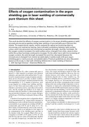
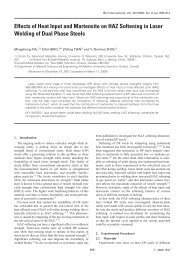
1 Carbon paper imprints <strong>of</strong> <strong>electrode</strong> tip surfaces a at<br />
start <strong>of</strong> <strong>electrode</strong> life (0 welds) <strong>and</strong> b at end <strong>of</strong> <strong>electrode</strong><br />
life (360 welds)<br />
10 mm <strong>and</strong> radius <strong>of</strong> curvature <strong>of</strong> 50 mm. The experimental<br />
results indicated that <strong>electrode</strong> degradation, as a<br />
result <strong>of</strong> metallurgical interactions between the copper<br />
<strong>electrode</strong> <strong>and</strong> aluminium sheet, occurred in four steps:<br />
aluminium pickup, <strong>electrode</strong> alloying with aluminium,<br />
<strong>electrode</strong> tip face <strong>pitting</strong>, <strong>and</strong> cavitation. A severely<br />
pitted <strong>electrode</strong> would result in <strong>electrode</strong> failure due to<br />
the formation <strong>of</strong> an undersize weld nugget.<br />
Figure 1 shows the carbon paper imprints <strong>of</strong> the tip<br />
surfaces <strong>of</strong> a new <strong>and</strong> used <strong>electrode</strong> at the beginning<br />
<strong>and</strong> end <strong>of</strong> the <strong>electrode</strong> life, respectively. Perfect contact<br />
between <strong>electrode</strong> <strong>and</strong> sheet was achieved when the<br />
<strong>electrode</strong> was new. The severely pitted <strong>electrode</strong> at<br />
the end <strong>of</strong> its life exhibited a non-contacting region at<br />
the centre <strong>and</strong> an increased nominal contact diameter;<br />
this was because most <strong>of</strong> the central part was pitted <strong>and</strong><br />
could no longer be brought into contact with the sheet<br />
surface during welding. To study further the <strong>effect</strong> <strong>of</strong><br />
<strong>electrode</strong> <strong>pitting</strong> <strong>and</strong> cavitation on nugget formation,<br />
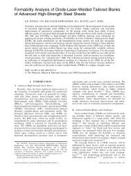
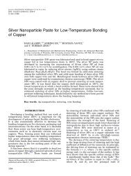
simulated <strong>electrode</strong>s (i.e. normal <strong>electrode</strong>s with a predrilled<br />
central hole <strong>of</strong> varying diameter from 1.0 to<br />
5.0 mm to model the severity <strong>of</strong> <strong>electrode</strong> <strong>pitting</strong>, as<br />
shown in Fig. 2) were used in welding experiments. The<br />
same welding parameters as used in the <strong>electrode</strong> tip life<br />
tests were used, i.e. welding current <strong>of</strong> 29 kA, <strong>electrode</strong><br />
force <strong>of</strong> 5 kN, squeeze time <strong>of</strong> 25 cycles, weld time <strong>of</strong><br />
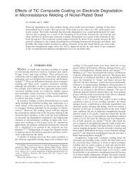
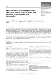
5 cycles, <strong>and</strong> hold time <strong>of</strong> 12 cycles. It was observed that<br />
the outside diameter <strong>of</strong> the carbon imprints increased<br />
as the hole diameter varied (Fig. 3). Comparing Fig. 3<br />
with Fig. 1, it could be seen that the varying degrees <strong>of</strong><br />
<strong>pitting</strong> could be represented fairly well by simply<br />
increasing the centre cavity diameter. In the present<br />
experimental work, the diameters <strong>of</strong> the buttons from<br />
peeled samples were measured, <strong>and</strong> the cross-sections <strong>of</strong><br />
2 Dimensions <strong>of</strong> a normal <strong>and</strong> b <strong>pitting</strong> simulation <strong>electrode</strong>s<br />
3 Carbon paper imprints <strong>of</strong> <strong>electrode</strong>s with pre-drilled<br />
hole diameters <strong>of</strong> a 1.0 <strong>and</strong> b 5.0 mm<br />
the nuggets formed were observed using an optical<br />
microscope.<br />
<strong>Finite</strong> <strong>element</strong> modelling<br />
The Ansys/MP5.7 (Ansys, Canonsburg, PA, USA)<br />
commercial finite <strong>element</strong> <strong>analysis</strong> code was employed<br />
in the present numerical <strong>analysis</strong>. The incrementally<br />
coupled electrical–thermal–mechanical algorithm developed<br />
in previous work 15 was adopted to model the<br />
RSW process using <strong>electrode</strong>s with pre-drilled holes <strong>of</strong><br />
different diameters, <strong>and</strong> the fundamentally based contact<br />
resistance model derived from microcontact theory<br />
was included in the finite <strong>element</strong> <strong>analysis</strong> procedure to<br />
take the contact resistances at the <strong>electrode</strong>/sheet <strong>and</strong><br />
sheet/sheet interfaces into account: details on how this<br />
contact resistance model was established <strong>and</strong> adopted in<br />
modelling can be found in Ref. 15.<br />
As an example, the top half <strong>of</strong> the finite <strong>element</strong> mesh<br />
used for a hole diameter <strong>of</strong> 3.0 mm is shown in Fig. 4.<br />
The boundary conditions in electrical–thermal <strong>analysis</strong><br />
were as follows:<br />
(i) the voltage at the bottom end <strong>of</strong> the lower<br />
<strong>electrode</strong> was set to zero, <strong>and</strong> a direct current <strong>of</strong><br />
29 kA was applied at the top end <strong>of</strong> the upper<br />
(ii)<br />
<strong>electrode</strong><br />
the electric current flow <strong>and</strong> heat transfer across<br />
the <strong>electrode</strong>/sheet <strong>and</strong> sheet/sheet interfaces<br />
were only allowed for the parts in contact with<br />
each other – whether the nodes at the interfaces<br />
were in contact or not was determined from the<br />
node to surface contact <strong>element</strong>s in thermal–<br />
mechanical <strong>analysis</strong> <strong>of</strong> a time step; in the<br />
electrical–thermal <strong>analysis</strong> <strong>of</strong> the following time<br />
step, the parts in contact were coupled to allow<br />
the current to flow through, whereas parts not in<br />
contact were not coupled <strong>and</strong> therefore no<br />
current could flow through<br />
(iii) studies by Browne et al. 16 showed that the<br />
convective heat transfer to the surrounding air<br />
is negligible <strong>and</strong> can be ignored, therefore the<br />
Science <strong>and</strong> Technology <strong>of</strong> Welding <strong>and</strong> Joining 2005 VOL 10 NO 1 62
Chang et al.<br />
<strong>Finite</strong> <strong>element</strong> <strong>analysis</strong> <strong>of</strong> <strong>electrode</strong> <strong>pitting</strong> in RSW <strong>of</strong> Al alloy<br />
5 Contact areas at <strong>electrode</strong>/sheet (E/S) <strong>and</strong> sheet/sheet<br />
(S/S) interfaces for <strong>electrode</strong>s with various diameters<br />
<strong>of</strong> pre-drilled hole under <strong>electrode</strong> force <strong>of</strong> 5.0 kN<br />
pr<strong>of</strong>iles in the workpieces, etc. Details are presented<br />
below.<br />
4 Top half <strong>of</strong> finite <strong>element</strong> mesh when <strong>pitting</strong> hole diameter<br />
is 3.0 mm<br />
outer surfaces for both <strong>electrode</strong> <strong>and</strong> sheets were<br />
assumed to be adiabatic – the <strong>effect</strong> <strong>of</strong> the<br />
cooling water in the <strong>electrode</strong> cavity was taken<br />
into account by assigning the ambient temperature<br />
(20uC) to the inner surfaces <strong>of</strong> the <strong>electrode</strong>.<br />
The boundary conditions used in the thermal–<br />
mechanical <strong>analysis</strong> included:<br />
(i) <strong>electrode</strong> force was applied as a uniformly<br />
distributed pressure at the top end <strong>of</strong> the upper<br />
<strong>electrode</strong>; the temperature calculated from electrical–thermal<br />
<strong>analysis</strong> was applied as a body<br />
(ii)<br />
load<br />
axial displacements at the bottom end <strong>of</strong> the<br />
lower <strong>electrode</strong> <strong>and</strong> radial displacement at the<br />
centreline were all constrained.<br />
Aluminium alloy 5182 <strong>and</strong> Cu–0.15 wt-%Zr <strong>electrode</strong>s<br />
were used in the present numerical work. The strongly<br />
temperature dependent electrical, thermal, <strong>and</strong> mechanical<br />
property parameters <strong>of</strong> the <strong>electrode</strong>s <strong>and</strong> aluminium<br />
alloy 5182 were taken from Ref. 17. Details <strong>of</strong> the<br />
sheet thickness, <strong>electrode</strong> diameters, <strong>and</strong> process parameters<br />
used in finite <strong>element</strong> <strong>analysis</strong> were the same as<br />
those used in experimental simulations, as presented in<br />
the previous subsection. Six cases were numerically<br />
studied, with the diameter <strong>of</strong> the pre-drilled hole varying<br />
from 0 (new <strong>electrode</strong>) to 5.0 mm with a constant<br />
increment <strong>of</strong> 1.0 mm.<br />
Results <strong>of</strong> finite <strong>element</strong> <strong>analysis</strong><br />
The mechanical, electrical, <strong>and</strong> thermal physical information<br />
were all computed <strong>and</strong> analysed via the finite<br />
<strong>element</strong> method. Many aspects were revealed <strong>and</strong><br />
quantitatively characterised that could not be measured<br />
or obtained by even the most ambitious experimental<br />
work, such as the contact area at the sheet/sheet interface,<br />
current density level <strong>and</strong> distribution, temperature<br />
Contact area at interfaces<br />
The contact areas at the <strong>electrode</strong>/sheet <strong>and</strong> sheet/sheet<br />
interfaces from finite <strong>element</strong> <strong>analysis</strong> are shown in Fig. 5<br />
for the <strong>electrode</strong> force <strong>of</strong> 5.0 kN.<br />
It can be seen that the nominal contact area (the area<br />
contained by the outer diameter <strong>of</strong> the contact region)<br />
between the <strong>electrode</strong> <strong>and</strong> the sheet increased gradually<br />
with increasing <strong>pitting</strong> hole diameter. Because the<br />
central part <strong>of</strong> the <strong>electrode</strong> was hollow, that part did<br />
not bear load. When the size <strong>of</strong> the <strong>pitting</strong> hole<br />
increased, the parts further away from the <strong>electrode</strong><br />
centreline were pushed into contact to counteract the<br />
same <strong>electrode</strong> force. With increasing <strong>pitting</strong> hole<br />
diameter, the actual contact area (nominal contact area<br />
minus the area <strong>of</strong> no contact in the central region) at the<br />
<strong>electrode</strong>/sheet interface remained fairly constant as the<br />
hole diameter varied <strong>and</strong> was almost the same for all<br />
cases. This implied that as the hole diameter increased,<br />
more <strong>electrode</strong> tip surface (having a curved pr<strong>of</strong>ile) sank<br />
into contact with the sheet until the equivalent actual<br />
contact area was reached to resist the same <strong>electrode</strong><br />
force.<br />
The contact areas at the sheet/sheet interface were<br />
much larger than that at the <strong>electrode</strong>/sheet interface for<br />
all cases. Increasing the <strong>pitting</strong> hole diameter D from 0<br />
to 1.0 mm hardly influenced the contact area at the<br />
sheet/sheet interface; however, when the <strong>pitting</strong> hole<br />
diameters were increased beyond 3.0 mm, the contact<br />
areas at the sheet/sheet interface increased significantly.<br />
As had been observed, the nominal contact areas at the<br />
<strong>electrode</strong>/sheet interface were increased with increasing<br />
<strong>pitting</strong> hole diameter; consequently, more material at the<br />
sheet/sheet interface was also pushed into contact under<br />
the action <strong>of</strong> the <strong>electrode</strong> force, <strong>and</strong> the contact area at<br />
the sheet/sheet interface was increased.<br />
Distribution <strong>of</strong> current density<br />
The distribution <strong>of</strong> welding current density at the<br />
<strong>electrode</strong>/sheet interface at the start <strong>of</strong> welding is shown<br />
in Fig. 6. It can be seen that for <strong>electrode</strong>s without<br />
<strong>pitting</strong> (D50 mm), the current density in the central<br />
Science <strong>and</strong> Technology <strong>of</strong> Welding <strong>and</strong> Joining 2005 VOL 10 NO 1 63
Chang et al.<br />
<strong>Finite</strong> <strong>element</strong> <strong>analysis</strong> <strong>of</strong> <strong>electrode</strong> <strong>pitting</strong> in RSW <strong>of</strong> Al alloy<br />
6 Current density distribution at <strong>electrode</strong>/sheet interface<br />
at start <strong>of</strong> welding for <strong>electrode</strong>s with various diameters<br />
<strong>of</strong> pre-drilled hole<br />
region was distributed evenly, <strong>and</strong> there was a current<br />
density peak at the edge <strong>of</strong> the contact region. As has<br />
been explained previously, 15 the current density peak<br />
was caused by the ‘edge <strong>effect</strong>’, in which the electric<br />
current tended to flow into the periphery <strong>of</strong> the contact<br />
region because <strong>of</strong> the smaller area <strong>of</strong> the contact region<br />
compared with the area <strong>of</strong> the <strong>electrode</strong> cross-section.<br />
For <strong>electrode</strong>s with <strong>pitting</strong> holes, the current density<br />
peaks appeared at both the inner <strong>and</strong> outer edges <strong>of</strong> the<br />
contact ring, <strong>and</strong> the peak current at the inner edge was<br />
lower than that at the outer edge. On increasing the<br />
<strong>pitting</strong> hole diameter, the current density peak value at<br />
the outer edge decreased somewhat whereas that at the<br />
inner edge increased slightly. Nevertheless, the overall<br />
levels <strong>of</strong> current density did not change significantly for<br />
different <strong>electrode</strong>s because the contact area between the<br />
<strong>electrode</strong> <strong>and</strong> sheet stayed fairly constant when the<br />
diameter <strong>of</strong> the <strong>pitting</strong> hole varied, as shown in Fig. 5.<br />
Figure 7 shows the current density distribution at the<br />
sheet/sheet interface at the start <strong>of</strong> spot welding. It can<br />
be seen that for the <strong>electrode</strong> without <strong>pitting</strong>, the current<br />
density was greatest at the centre <strong>of</strong> the contact region.<br />
7 Current density distribution at sheet/sheet interface at<br />
start <strong>of</strong> welding for <strong>electrode</strong>s with various pre-drilled<br />
hole diameters<br />
8 Temperature distribution at sheet/sheet interface at<br />
end <strong>of</strong> welding for <strong>electrode</strong>s with various pre-drilled<br />
hole diameters<br />
There was also a small current density peak at the<br />
periphery <strong>of</strong> the contact region, but the peak current<br />
density was lower than that at the centre, <strong>and</strong> the<br />
concentration was not as significant as that at the<br />
<strong>electrode</strong>/sheet interface. Increasing the <strong>pitting</strong> hole<br />
diameter to 1 mm would not exert a strong influence<br />
on the current density distribution. However, on<br />
increasing the hole diameter to 3.0 mm, the current<br />
density at the faying surface reduced greatly owing to<br />
the increase in contact area, <strong>and</strong> the maximum current<br />
density no longer occurred at the centreline but started<br />
to shift away from the centreline. Increasing the <strong>pitting</strong><br />
hole diameter further caused the current density to<br />
decrease further also, because <strong>of</strong> the significant increase<br />
<strong>of</strong> contact area at the faying surface, as can be seen from<br />
the current density distribution when D55.0 mm. It is<br />
well known that the current density is the most<br />
important quantity influencing nugget formation <strong>and</strong><br />
growth because the heat generation is proportional to<br />
the square <strong>of</strong> the welding current. It is predictable that<br />
when the <strong>electrode</strong> <strong>pitting</strong> developed to a certain degree,<br />
<strong>and</strong> current density was reduced excessively, the heat<br />
generated would not be sufficient for nugget formation<br />
<strong>and</strong> growth <strong>and</strong> only partial melting or even no melting<br />
could occur at the faying surface; this has been clearly<br />
demonstrated in Fig. 8.<br />
Temperature distribution at end <strong>of</strong> welding<br />
Temperature distribution at the sheet/sheet interface at<br />
the end <strong>of</strong> spot welding (5 cycles) is shown in Fig. 8. It<br />
can be seen that for a new <strong>electrode</strong> without <strong>pitting</strong>,<br />
the temperature was highest in the central region. The<br />
radius <strong>of</strong> the region at a temperature above 573uC (the<br />
melting point <strong>of</strong> AA5182) was about 3.5 mm, indicating<br />
that the diameter <strong>of</strong> the molten nugget was about<br />
7.0 mm, which was consistent with the experimental<br />
observation. 3 Increasing the <strong>pitting</strong> hole diameter from<br />
zero to 1 mm would not affect the dimensions <strong>of</strong> the<br />
melted region, <strong>and</strong> basically the same size <strong>of</strong> nugget as<br />
that for D50 mm would form under such conditions, as<br />
can be concluded from the essentially identical temperature<br />
distributions for these two cases (D50 <strong>and</strong><br />
1.0 mm). When the <strong>pitting</strong> hole diameter increased to<br />
3.0 mm, the temperature at the sheet/sheet interface was<br />
Science <strong>and</strong> Technology <strong>of</strong> Welding <strong>and</strong> Joining 2005 VOL 10 NO 1 64
Chang et al.<br />
<strong>Finite</strong> <strong>element</strong> <strong>analysis</strong> <strong>of</strong> <strong>electrode</strong> <strong>pitting</strong> in RSW <strong>of</strong> Al alloy<br />
a<br />
b<br />
c<br />
d<br />
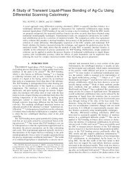
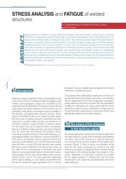
9 Nugget shape <strong>and</strong> dimensions obtained from numerical prediction (left h<strong>and</strong> side) <strong>and</strong> experimental observation (right<br />
h<strong>and</strong> side) for <strong>electrode</strong>s with <strong>pitting</strong> hole diameters <strong>of</strong> a 0, b 1.0, c 3.0, <strong>and</strong> d 5.0 mm<br />
decreased, <strong>and</strong> the region at a temperature higher than<br />
the melting point <strong>of</strong> the aluminium alloy was reduced,<br />
indicating that the thickness <strong>and</strong> the diameter <strong>of</strong> the<br />
nugget would decrease. For the <strong>pitting</strong> hole diameter <strong>of</strong><br />
5.0 mm, the temperature at the centre part did not reach<br />
the melting point <strong>of</strong> AA5182, indicating that no melting<br />
occurred <strong>and</strong> no nugget formed at the centre; at the<br />
same time, it can be seen that a small region about 3 mm<br />
away from the centreline reached temperatures above<br />
the melting point <strong>of</strong> the present aluminium alloy,<br />
indicating that a nugget in the shape <strong>of</strong> a ring was<br />
formed in that region under such welding conditions.<br />
Comparison between experimental simulations<br />
<strong>and</strong> numerical <strong>analysis</strong><br />
Figure 9 shows a direct comparison <strong>of</strong> the predicted<br />
temperature distribution (left h<strong>and</strong> side <strong>of</strong> the figure)<br />
<strong>and</strong> the experimentally obtained shape <strong>and</strong> dimensions<br />
<strong>of</strong> nuggets (right h<strong>and</strong> side <strong>of</strong> the figure) on the crosssections<br />
<strong>of</strong> the samples for D50, 1.0, 3.0, <strong>and</strong> 5.0 mm,<br />
respectively. The dark regions in the finite <strong>element</strong><br />
<strong>analysis</strong> results represent the nuggets, which reached<br />
temperatures higher than the melting point <strong>of</strong> AA5182<br />
(573uC). When spot welded with a new <strong>electrode</strong>, the<br />
experimentally obtained nugget diameter was about<br />
7.0 mm (Fig. 9a), which agreed very well with the<br />
calculation. When the <strong>pitting</strong> hole was 1.0 mm in<br />
diameter, the nugget diameter was almost the same as<br />
that for the <strong>electrode</strong> without <strong>pitting</strong> (Fig. 9b); hence,<br />
the presence <strong>of</strong> small pre-drilled holes in the <strong>electrode</strong>s<br />
did not have a detrimental influence on nugget formation.<br />
However, when the <strong>pitting</strong> hole diameter increased<br />
to 3.0 mm, both temperature pr<strong>of</strong>ile <strong>and</strong> nugget<br />
diameter were reduced significantly (Fig. 9c). When the<br />
<strong>pitting</strong> hole diameter reached 5.0 mm, only a small<br />
nugget formed in a toroidal shape without any melting<br />
in the central region (Fig. 9d). This indicates that severe<br />
<strong>electrode</strong> <strong>pitting</strong> is unfavourable to the weld quality<br />
since a larger pitted area on the <strong>electrode</strong> surface will<br />
result in a larger contact area <strong>and</strong> lower current density<br />
at the sheet/sheet interface, <strong>and</strong> hence the formation <strong>of</strong><br />
undersized nuggets. The experimental results are in good<br />
agreement with numerical predictions, which proves the<br />
validity <strong>of</strong> the established finite <strong>element</strong> model in<br />
studying the influence <strong>of</strong> <strong>electrode</strong> <strong>pitting</strong> on the spot<br />
welding quality.<br />
Summary<br />
The <strong>effect</strong> <strong>of</strong> <strong>electrode</strong> <strong>pitting</strong> on the weld nugget<br />
formation in RSW <strong>of</strong> an aluminium alloy was investigated<br />
using the finite <strong>element</strong> method. The calculations<br />
were validated by a corresponding experimental simulation,<br />
in which <strong>electrode</strong>s (<strong>of</strong> tip face diameter 10 mm<br />
<strong>and</strong> radius <strong>of</strong> curvature 50 mm) with a pre-drilled hole<br />
<strong>of</strong> varying diameter were used in RSW <strong>of</strong> 1.5 mm<br />
thickness sheet aluminium alloy 5182 using a medium<br />
frequency direct current welder. The results showed that<br />
when the <strong>pitting</strong> hole was small, the temperature, <strong>and</strong><br />
hence nugget formation, was not affected very strongly.<br />
On increasing the <strong>pitting</strong> hole diameter further, beyond<br />
3.0 mm, the nominal contact area at the <strong>electrode</strong>/sheet<br />
interface increased, whereas the actual contact area at<br />
this interface did not change significantly; conversely,<br />
the contact area at the sheet/sheet interface was<br />
increased significantly on increasing the <strong>pitting</strong> hole<br />
diameter to greater than 3.0 mm, <strong>and</strong> the current density<br />
at this interface was reduced greatly. The temperature<br />
<strong>and</strong> nugget size started to decrease for <strong>pitting</strong> holes<br />
greater than 3.0 mm in diameter. When the <strong>pitting</strong> hole<br />
diameter reached 5.0 mm, a small nugget formed in a<br />
Science <strong>and</strong> Technology <strong>of</strong> Welding <strong>and</strong> Joining 2005 VOL 10 NO 1 65
Chang et al.<br />
<strong>Finite</strong> <strong>element</strong> <strong>analysis</strong> <strong>of</strong> <strong>electrode</strong> <strong>pitting</strong> in RSW <strong>of</strong> Al alloy<br />
toroidal shape without melting in the central region.<br />
The numerical calculation <strong>of</strong> the nugget shape <strong>and</strong><br />
dimensions agreed well with the experimental results.<br />
The present study confirmed that a severely pitted area<br />
on the <strong>electrode</strong> surface was a major cause <strong>of</strong> decreased<br />
weld quality in terms <strong>of</strong> nugget size <strong>and</strong> hence joint<br />
strength during RSW <strong>of</strong> aluminium alloys because <strong>of</strong><br />
the increased contact area, <strong>and</strong> hence reduced current<br />
density, at the sheet/sheet interface.<br />
Acknowledgement<br />
The present project is sponsored by the Scientific<br />
Foundation for Returned Overseas Chinese Scholars,<br />
Ministry <strong>of</strong> Education, People’s Republic <strong>of</strong> China. The<br />
authors would also like to acknowledge the financial<br />
support from the Natural Sciences <strong>and</strong> Engineering<br />
Research Council (NSERC) <strong>of</strong> Canada.<br />
References<br />
1. B. Irving: Weld. J., 1995, 74, (8), 29–34.<br />
2. R. M. Rivett <strong>and</strong> S. A. Westgate: Met. Constr.,1980,12, (10), 510–517.<br />
3. S. Fukumoto, I. Lum, E. Biro, D. R. Boomer <strong>and</strong> Y. Zhou: Weld.<br />
J., 2003, 82, (11), 307s–312s.<br />
4. M. R. Finlay: Aust. Weld. Res., CRC, 1996, 18, 21.<br />
5. G. L. Leone <strong>and</strong> B. Altshuller: ‘Improvement on the resistance spot<br />
weldability <strong>of</strong> aluminum body sheet’, Technical Paper 840292,<br />
Society <strong>of</strong> Automotive Engineers, Warrendale, PA, USA, 1984.<br />
6. R. M. Rivett: ‘Spot welding <strong>electrode</strong> life tests on aluminium<br />
sheet – <strong>effect</strong> <strong>of</strong> parent metal composition <strong>and</strong> surface treatment’,<br />
Report 132, The Welding Institute, Abington, Cambs., UK,<br />
1980.<br />
7. E. P. Patrick <strong>and</strong> D. J. Spinella: Proc. AWS Sheet Metal Welding<br />
Conf., Detroit Section VII, Troy, MI, October 1996, American<br />
Welding Society, paper B4.<br />
8. Y. Tanaka <strong>and</strong> M. Noguchi: Weld. Int., 1987, 11, 1074–<br />
1078.<br />
9. M. A. Glagola <strong>and</strong> A. R. Calvin: ‘Nickel plated <strong>electrode</strong>s for spot<br />
welding aluminum’, Technical Paper 760167, Society <strong>of</strong><br />
Automotive Engineers, Warrendale, PA, USA, 1976.<br />
10. R. Ikeda, K. Yasuda, K. Hashiguchi, T. Okita <strong>and</strong> T. Yahaba:<br />
Proc. Advanced Technologies <strong>and</strong> Processes (IBEC ’95), SAE, 44–<br />
51; 1995, Michigan, Warren.<br />
11. W. Chuko <strong>and</strong> J. Gould: Proc. TMS 2001 Annual Meeting,<br />
Aluminum Automotive <strong>and</strong> Joining Symposia, 139–154; 2001,<br />
Warrendale, PA, TMS.<br />
12. U. Dilthey <strong>and</strong> H. Sven: Weld. Cutting, 1998, (1), 34–40.<br />
13. I. Lum, S. Fukumoto, E. Biro, D. R. Boomer <strong>and</strong> Y. Zhou: Metall.<br />
Mater. Trans. A, 2004, 35A, (1), 217–226.<br />
14. E. P. Patrick, J. R. Auhl <strong>and</strong> T. S. Sun: ‘Underst<strong>and</strong>ing the process<br />
mechanisms is key to reliable resistance spot welding aluminum<br />
auto body components’, Technical Paper 840291, Society <strong>of</strong><br />
Automotive Engineers, Warrendale, PA, USA, 1984.<br />
15. B. H. Chang, M. V. Li <strong>and</strong> Y. Zhou: Sci. Technol. Weld. Joining,<br />
2001, 6, (5), 273–280.<br />
16. D. J. Browne, H. W. Ch<strong>and</strong>ler, J. T. Evans <strong>and</strong> J. Wen: Weld. J.,<br />
1995, 74, (10), 339s–344s.<br />
17. ‘Metals h<strong>and</strong>book’, 9th edn, Vol. 2, ‘Properties <strong>and</strong> selection:<br />
nonferrous alloys <strong>and</strong> pure metals’, 45–92; 1979, Metals Park, OH,<br />
USA, American Society for Metals.<br />
Science <strong>and</strong> Technology <strong>of</strong> Welding <strong>and</strong> Joining 2005 VOL 10 NO 1 66