THE ENGINE INDICATOR - Archivingindustry.com
THE ENGINE INDICATOR - Archivingindustry.com
THE ENGINE INDICATOR - Archivingindustry.com

Create successful ePaper yourself
Turn your PDF publications into a flip-book with our unique Google optimized e-Paper software.
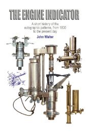
<strong>THE</strong> <strong>ENGINE</strong> <strong>INDICATOR</strong>
<strong>THE</strong> <strong>ENGINE</strong><br />
<strong>INDICATOR</strong><br />
A CONCISE GUIDE TO <strong>THE</strong><br />
IDENTIFICATION OF AUTOGRAPHIC<br />
INSTRUMENTS<br />
JOHN WALTER<br />
<strong>THE</strong> CANADIAN MUSEUM OF MAKING<br />
in association with<br />
NEVILL PUBLISHING
First published in 2008 by<br />
<strong>THE</strong> CANADIAN MUSEUM OF MAKING<br />
www.museumofmaking.org<br />
with the assistance of<br />
Nevill Publishing & Design, Hove, England<br />
Copyright © John Walter, 2008, 2011<br />
Updated to 7th July 2011<br />
The right of John Walter to be identified as the author of this work has been asserted by him<br />
in accordance with the Copyright, Designs and Patents Act of 1988.<br />
All rights reserved<br />
This chapter has been up-loaded<br />
to allow free access to information as ‘work in progress’.<br />
Other chapters will be made available as they are <strong>com</strong>pleted:<br />
please check our websites for details.<br />
PRODUCED BY JOHN WALTER<br />
e-mail: johnwalter883@btinternet.<strong>com</strong> • website: www.archivingindustry.<strong>com</strong>
A CONCISE GUIDE<br />
Introduction<br />
“…The Indicator is a means of recording the pressure and rate of pressure<br />
change in an engine cylinder at all points of the cycle, and provides…an<br />
important indication of the efficiency and working of details of the engine.<br />
With proper study of the diagrams, maximum economy with a low fuel bill,<br />
small cost of repairs, greater output, an even speed, absence of breakdowns,<br />
minimum loss from depreciation and consequently longer life can be<br />
attained…’ A quotation from The Engine Indicator, a small handbook published<br />
by Dobbie McInnes Ltd of Glasgow, the leading British indicator manufacturer<br />
of the twentieth century.<br />
The advent in the first decade of the eighteenth century of the New<strong>com</strong>en<br />
atmospheric engine—the predecessor of the true steam engine—was a huge<br />
step forward technologically. However, the ready availability of fuel in the<br />
collieries the engines were designed to drain was initially a great inhibitor to<br />
improving their efficiency; that they worked well mattered much less than<br />
that they worked at all. There was no experience to guide the first engine<br />
erectors, and no yardstick by which output could be gauged.<br />
The first man known to have investigated the atmospheric engine with<br />
real purpose was the English engineer John Smeaton (1724–92), born in the<br />
small village of Austhorpe, near Leeds, and inspired by stories of the local<br />
engine that had been only the sixth of its type to be erected.[ 1 ] The failure of<br />
his own New River Engine of 1767 to fulfil expectations persuaded Smeaton<br />
to undertake exhaustive studies of engines working in the Northumberland<br />
coalfields and the Cornish tin mines. He was also the populariser of an<br />
arithmetical expression of the ‘Duty’ of individual machines.<br />
It seems unlikely that Smeaton himself originated the concept of ‘Duty’,<br />
but he was the first to link it with the amount of work that could be done in<br />
1. The identification of the earliest New<strong>com</strong>en engines is still contentious. There were probably two<br />
prototypes, and then the first of the working installations—Coneygree coal works, Tipton (‘Dudley Castle’),<br />
1712; Griff Colliery, 1714; Woods Mine, Hawarden, 1714/15; and Moor Hall, Austhorpe, 1714/15.<br />
v
<strong>THE</strong> <strong>ENGINE</strong> <strong>INDICATOR</strong><br />
a particular time. Virtually all of the atmospheric engines working in Britain<br />
in the 1760s were being used to drain huge quantities of water from mines,<br />
and it is no great surprise, therefore, that Smeaton should base his calculation<br />
on the weight of water that was being lifted. His ‘time frame’ was effectively<br />
the length of time taken to burn a bushel of coal.[ 2 ]<br />
Among the useful features of Smeaton’s work are lists of the atmospheric<br />
engines that had been erected prior to 1769, as he had <strong>com</strong>missioned the<br />
erector William Brown to survey the installations in northern England and<br />
Scotland and had probably asked John Nancarrow to undertake similar work<br />
in Cornwall. The oldest (and probably also the smallest) of the 98 machines<br />
assessed by Brown had either been reduced to stand-by or were no longer in<br />
use by the time of survey, but the cylinder dimensions of most of them were<br />
known—diameters ranging from merely thirteen inches, in the cases of the<br />
Black Close, Norwood and one of the four Throckley engines, to ‘75 inchers’<br />
in Tynemouth Moor and Benwell collieries.[ 3 ]<br />
Smeaton selected fifteen Tyneside engines for detailed study, from which<br />
he calculated for each one not only ‘Duty’ but also ‘Great Product’ (the weight<br />
of water lifted through one foot each minute). Perhaps to Smeaton’s surprise,<br />
additional size did not necessarily generate additional power: one of the 75-<br />
inch engines, for example, returned a Duty of 4·59 million <strong>com</strong>pared with<br />
5.88 million for a 60-inch example. Horsepower was subsequently deduced<br />
to be 37.6 and 40.8 respectively.[ 4 ]<br />
A trial undertaken in Cornwall in the late 1770s produced similar results.<br />
Fifteen engines in Wheal Virgin, Poldice, Wheal Maid, Dolcoath and Wheal<br />
Chance, all with cylinder diameters of 60–70 inches, returned Duties of<br />
5·02–7·63 million. Horsepower ranged from only 14·78 for the Poldice 60-<br />
inch (which with a Duty of 7·17 million was regarded as the best engine in<br />
Cornwall) to 29·65 for the 70-inch Wheal Virgin New Engine. The running<br />
speeds were slow, averaging only a little over six strokes each minute.<br />
2. There was then no ‘national standard’ for the weight of a bushel of coal, which, consequently, varied<br />
according to district. The London bushel weighed 88lb; the Newcastle bushel weighed 84lb; and it was not<br />
un<strong>com</strong>mon to encounter a bushel of 90lb or 96lb in Cornwall.<br />
3. Many of the mines of the day had more than one engine, the result of a perpetual search for additional<br />
pumping capacity that was almost always satisfied on the basis that biggest was best. Byker Pit had six<br />
engines in 1769, Benton had five; and Heaton, Jesmond, Newbiggin, Throckley. Tynemouth Moor and<br />
Whitehaven had four apiece.<br />
4. The concept of ‘horsepower’ as a method of <strong>com</strong>paring output of engines dated back at least as far as<br />
the work of Thomas Savery (1702). Smeaton calculated in the 1770s that a horse (a pit pony, perhaps) was<br />
capable of an output of 22916 ft.lb/min, but experiments undertaken by James Watt in the 1780s with a<br />
‘brewery horse’ suggested that Smeaton’s value underestimated the power of the average animal. In 1783,<br />
therefore, Boulton & Watt standardised their horsepower as equivalent to 33000 ft.lb/min.<br />
vi
A CONCISE GUIDE<br />
Plate 0-1. This reproduction of an engraving by Thomas Barney, originally dating from<br />
1719, is the earliest known illustration of a New<strong>com</strong>en atmospheric engine—in this case,<br />
the so-called ‘Dudley Castle’ engine erected in 1712. John Walter collection.<br />
Consequently, John Smeaton was among the first people to recognise<br />
that many of the engines of his day were as badly designed as they were<br />
poorly made, identifying, among other factors, cylinders which were badly<br />
proportioned; fire-grates which were poorly positioned; boilers which were<br />
weak and badly made; steam pipes which were customarily far too small; and<br />
vii
<strong>THE</strong> <strong>ENGINE</strong> <strong>INDICATOR</strong><br />
that the water used to condense the steam was introduced to the cylinder<br />
much too abruptly to create an effective vacuum.<br />
The <strong>com</strong>mercial success of Watt engines occurred at the end of John<br />
Smeaton’s life, before he was able to make any use of the engine indicator<br />
developed initially by Watt and then by Watt & Southern (see Chapter One).<br />
However, it is to Smeaton that much of the impetus to develop testing systems<br />
should rightly be credited.<br />
The introduction of the indicator, and in particular the post-1796 movingtablet<br />
design, not only allowed the performance within the cylinder to be<br />
investigated but also acted as a catalyst to improve efficiency. There was a<br />
sound <strong>com</strong>mercial reason for this: Watt engines were often licensed on the<br />
basis of fees paid against performance; the greater the Duty, therefore, the<br />
greater would be the returns. A survey of more than twenty Watt engines<br />
working in Cornwall in 1798 showed an average Duty of 17·67 million—three<br />
times that of the New<strong>com</strong>en atmospheric engines reported only twenty years<br />
previously. The best of the Watt machines had given a Duty of 27·5 million.<br />
The publication of performance tables in the Philosophical Magazine<br />
encouraged <strong>com</strong>petition among mine captains; ‘Greatest Duty’ was a source<br />
of particular pride amongst these Cornish enginemen, and each vied to be<br />
at the head of the list. Consequently, Cornwall saw many of the earliest<br />
advances at first hand, with the erection of Trevithick high-pressure engines<br />
and Hornblower or Woolf <strong>com</strong>pounds.<br />
Duty grew rapidly. This was undoubtedly due in part to ever-increasing<br />
size, but also reflected improved efficiency. In 1814, for example, the Stray<br />
Figure 0–1: a tracing of a diagram taken in March 1803 from a single-cylinder<br />
Watt condensing engine. From Power from Steam, by Richard L. Hills<br />
viii
A CONCISE GUIDE<br />
Park engine (34·1 horsepower), a Watt-type machine with a 63-inch diameter<br />
cylinder and a stroke of 7ft 9in, had given an average monthly duty of 32·03<br />
million. In August 1816, the old 45-inch Wheal Chance engine was altered<br />
from its original single-cylinder Watt configuration to a two-cylinder Woolf<br />
<strong>com</strong>pound, Duty leaping from 25·37 million in July to 44·35 in September. By<br />
1839, the single-cylinder Cornish Engines, working expansively with highpressure<br />
steam, were returning impressive performances: the 80-inch West<br />
Julia machine (120·9hp), with a piston stroke of eleven feet, gave a Duty of<br />
73·94 million, and the Consolidated Mines 80-inch Davey engine (159hp) gave<br />
70·35 million. During this period, steam pressures associated with these huge<br />
engines had risen from barely above atmospheric level to 30–40 lb/sq.in; and<br />
coal consumption had been reduced from 25–30 lb/hp/hr to 7–8 lb/hp/hr.<br />
The introduction of the McNaught indicator (described in Chapter One),<br />
even though distribution was initially very slow, simplified assessments to<br />
a point where they became routine. This was particularly important, as the<br />
advent of high-pressure engines, pioneered near-simultaneously by Oliver<br />
Evans in the USA and Richard Trevithick in Britain, placed ever-increasing<br />
premiums on performance.[ 5 ]<br />
One long-lasting consequence of the use of indicators, which allowed<br />
a precise calculation of ‘indicated horsepower’, was the demise of the older<br />
system of analysis. Though ‘Duty’ had been a valuable method of assessment<br />
at a time when none other existed, the basis on which it was calculated was<br />
open to criticism. The quantity of coal was usually assessed on a monthly<br />
basis, making no allowance for the times the engine stood idle or the fuel<br />
that was used to fire-up; nor were the effects of inertia and friction in the<br />
pump rodding taken into account. Consequently, horsepower calculated on<br />
the basis of Great Product was often substantially lower than each engine was<br />
actually delivering.[ 6 ]<br />
The use of indicators eliminated many errors, though a dynamometer<br />
was still required to allow the mechanical efficiency (and hence the useful<br />
output) to be deduced. It is reckoned that the thermodynamic efficiency of<br />
the New<strong>com</strong>en engines was only about one per cent, improved by even the<br />
5. The exploits of Trevithick (1771–1833) and Evans (1755–1819), which were very controversial at a time<br />
of ultra-conservatism, seem to have occurred independently. Both men saw cumbersome construction<br />
and feeble boiler pressures as inhibitors to progress. Trevithick, in particular, pioneered self-contained<br />
non-condensing engines, road carriages and the railway lo<strong>com</strong>otive.<br />
6. Very few indicator diagrams were ever taken from atmospheric engines, and, consequently, even fewer<br />
survive. Diagrams obtained in 1895 from a ‘66-inch’ engine erercted in Ashton Gate, Bristol, gave 51.4ihp.<br />
Even though this particular machine had been greatly altered, undoubtedly improving performance, it<br />
seems very unlikely that it would have given much more than 30hp assessed on the basis of Duty.<br />
ix
<strong>THE</strong> <strong>ENGINE</strong> <strong>INDICATOR</strong><br />
x
A CONCISE GUIDE<br />
Plate 0-2. The title page of the 1875-edition of the book promoting the improved form of<br />
the Hopkinson indicator, typical of the grandiose style of the day. Note the drawing of the<br />
indicator in the central oval. Museum of Making collection.<br />
finest of the Watt engines only to little more than two per cent. Mechanical<br />
efficiency of the best New<strong>com</strong>en engines was 65–75 per cent; Watt engines<br />
were better, returning 75–85 per cent.<br />
As early as the 1840s, the British engineer Daniel Gooch (1816–89) was<br />
indicating railway lo<strong>com</strong>otives—even then running with boiler pressures of<br />
120 lb/sq.in—and Jacob Perkins (1766–1849) had produced boilers capable of<br />
withstanding pressures more than ten times higher. The rapid rises in piston<br />
speeds and operating pressures were initially handled merely by increasing<br />
the strength of indicator springs, but the problems of vibration also grew to a<br />
point where the validity of the traces was often <strong>com</strong>promised.<br />
The McNaught indicator was still rarely seen in 1857, when Enoch Gledhill<br />
wrote to Joseph Hopkinson that ‘In travelling the country, I find that a great<br />
number of owners of Engines have yet to derive the advantages which others<br />
are deriving by allowing the steam to expand before leaving the cylinder. The<br />
reason of this is, that the means of carrying out expansion and early exhaust<br />
are but little understood by those who ought to have a practical knowledge of<br />
the subject. No doubt one great cause is a want of a more general knowledge<br />
of the Indicator…’<br />
Hopkinson also remarked that, when an engine in a Dewsbury Mill tested<br />
poorly in 1859, the ‘Engineer…could not agree with the report, as established<br />
by the diagram, that his Engine valves were improperly set, “because”, as he<br />
said, “he had had great practice with the Engines”. He would not accept the<br />
facts pointed out by the Indicator, because of that most silly of all reasons—<br />
long habit in a certain rule and routine…’<br />
Testimony such as this suggests that the engine indicator, far from being<br />
<strong>com</strong>monplace, was rarely seen in 1860 and it is tempting to conclude that<br />
total production at this point could be numbered more in hundreds than<br />
thousands. However, though some engineers remained hostile, often because<br />
it suggested their grandiose claims to be mistaken, the advent and large-scale<br />
manufacture of the Richards indicator from 1863 onward (see Chapter Two)<br />
was too great a step to be retraced.<br />
The Richards indicator, though retaining popularity for use with slowspeed<br />
steam engines until the beginning of the First World War, was rapidly<br />
supplemented by improved designs with lighter amplifying systems. Often<br />
specifically designed for use with high-speed machinery, these included<br />
xi
<strong>THE</strong> <strong>ENGINE</strong> <strong>INDICATOR</strong><br />
xii
A CONCISE GUIDE<br />
the principal US patterns: the Thompson of 1875, the Tabor of 1878 and the<br />
Crosby of 1882 (all included in Chapter Three).<br />
The amplifying reciprocating-drum indicator was an extremely flexible<br />
tool, easily adaptable for use with fast-running high pressure steam engines,<br />
multi-cylinder internal-<strong>com</strong>bustion engines, hydraulic equipment, guns,<br />
<strong>com</strong>pressors, pumps and other pressure vessels. Among the most important<br />
catalysts in its success was the introduction in Britain of the Boiler Explosions<br />
Act of 1882, the inspiration for later amendments and <strong>com</strong>parable legislation<br />
accepted in France, Germany, the USA and elsewhere prior to 1914.<br />
The increasingly frequency with which boilers failed soon attracted<br />
public attention. The earliest attempt at regulation seems to have been a<br />
maritime boilermexplosions act pased in the USA on 7th July 1838, seeking<br />
to prevent needless loww of life on thr steamboats plying rivers such as the<br />
Mississippi. This was succeeded by the Steamboat Act of 30th May 1852, then<br />
by an extensive revision of procedures in February 1871.<br />
Plate 0–3 (previous page) and Plate 0–4. A survey of a two-cylinder tandem <strong>com</strong>pound<br />
steam engine owned by paper manufacturers Albert E. Reed & Co. Ltd, undertaken in<br />
March 1906, produced several diagrams from an Elliott-Richards indicator and a letter from<br />
the insurers detailing a variety of problems. John Walter collection.<br />
xiii
<strong>THE</strong> <strong>ENGINE</strong> <strong>INDICATOR</strong><br />
Plate 0–5. This Dobbie McInnes Design No. 1A indicator, no. 16813L dating from c. 1917, is<br />
known to have been used by a Surveyor employed by the British Engine Boiler & Electrical<br />
Insurance Co. Ltd. Unlike standard Design No. 1A instruments, which have the distinctively<br />
arched tracer bar, the ‘L’ type has a straight arm and a large drum intended for use with<br />
Richards-type paper. John Walter collection.<br />
The British were initially much less keen to hamstring industrial development<br />
with restrictive legislation. Eventually, however, a spate of accidents—in 1859,<br />
51 boiler explosions had cost 107 lives—inspired the creation of specialist<br />
insurance societies, beginning in Manchester in the middle of the nineteenth<br />
century. The effects were immediate and beneficial; only eight of the first<br />
eleven thousand boilers to be insured by societies failed within a year of<br />
inspection, <strong>com</strong>pared with more than 260 among the uninspected/uninsured<br />
group. Yet the most parsimonious boiler-users were reluctant to spend money<br />
on inspections and trusted instead to providence. Not surprisingly, as the use<br />
of steam plant increased so the accidents increased in proportion.<br />
By 1880, the problem had be<strong>com</strong>e sufficiently acute to persuade the British<br />
Government to intervene. The Act of 1882 (Victoria 45 & 46, c. 22) and its<br />
1890 amendment (Vistoria 53 & 54, c. 35) not only made insurance obligatory,<br />
xiv
A CONCISE GUIDE<br />
but introduced severe penalties if negligence on behalf of the owners or<br />
their representatives could be proved in court. Ironically, statistics show<br />
that accidents increased substantially in the decade after the 1882 Act had<br />
first been implemented, but this camouflages the rapid rise in the number of<br />
boilers in use in Britain, their ever-increasing <strong>com</strong>plexity, and possibly also the<br />
failure of old plant that had deteriorated before legislation could be enforced.<br />
Returns for 1894, the worst year, showed 115 explosions and collapses, causing<br />
32 deaths; in 1930, the figures were 56 and five respectively.<br />
Inspections were facilitated by the use of indicators, which could show<br />
if engines and boilers were properly matched; if the steam lines were too<br />
constricted; or if the valve gear was adjusted to make best use of the steam<br />
supply. In 1930, the British Engine Boiler & Electrical Insurance Co. Ltd,<br />
based in Manchester, had 22 branch offices scattered throughout the United<br />
Kingdom from Plymouth in the south to Dundee in the north. The ‘Classes<br />
of Business Transacted’ included ‘Boilers, and other Vessels under pressure,<br />
Steam and Feed Piping used for Power, Heating, Cooking and Manufacturing<br />
Processes insured against Explosion and Collapse…’<br />
The annual Technical Report stated that ‘In all the foregoing classes of<br />
insurance the interests of both the Insured and the Insurer are protected by the<br />
system of periodical inspections, which are made by the Company’s own staff<br />
of Surveyors, specially trained for the different branches of work. After each<br />
visit of a Surveyor, a report is sent to the Insured pointing out any defects that<br />
may have been detected, with advice as to the best means of remedying them.’<br />
This particular <strong>com</strong>pany is known to have used Dobbie McInnes indicators,<br />
as a substantial number of Design No. 1 instruments (often showing nonstandard<br />
modifications) were sold by auction in the 1980s.<br />
The letter reproduced as Plate 0–3 notes an inspection undertaken in<br />
March 1906 by a surveyor of the National Boiler & Insurance Co. Ltd, when<br />
faults were found during a trial of ‘No. 2 Horizontal Tandem Compound<br />
Condensing Steam Engine, Cylinders 11˝ & 20˝ diameter × 30˝ stroke’ owned<br />
by Albert E. Reed & Co. Ltd of Tovil Paper Mills, Tovil, Maidstone, Kent. The<br />
diagrams were taken with an Elliott-Richards indicator.<br />
Indicators remained at the forefront of engine-testing for many years,<br />
adapting from the steam engine to the many forms of internal-<strong>com</strong>bustion<br />
engine that were unknown in all but the most obscure rudimentary forms<br />
when the Richards indicator appeared in the early 1860s.<br />
One of the most important modifications to be made prior to 1914 was<br />
the introduction of special recorders, sometimes driven by clockwork, to<br />
enable performance to be monitored continuously. This was particularly<br />
xv
<strong>THE</strong> <strong>ENGINE</strong> <strong>INDICATOR</strong><br />
valuable owing to the rapid introduction of the fast running multi-cylinder<br />
petrol engines destined for motor vehicles and aeroplanes. In a contribution<br />
to a discussion arising out of a ‘symposium of Papers on Indicators’ given by<br />
the Institution of Mechanical Engineers in January-February 1923, Captain<br />
H. Riall Sankey of the Marine Oil-Engines Trial Committee observed that<br />
‘Going back to the old steam-engines running at very few revolutions, the<br />
diagrams were large, and the pencil could be seen moving over the paper;<br />
there was practically no shock from the steam and no inertia. These diagrams<br />
gave the indicated power of the engine to under one-half of 1 per cent. With<br />
a high-speed steam-engine there was still no shock, but there was inertia and<br />
the diagrams were small...<br />
‘[He recalled that]…in the classic trials by Willans the Crosby indicator<br />
was used, and Willans stated that they produced clear and measurable<br />
diagrams at 400 r.p.m., the inaccuracy probably did not exceed 1 per cent. In<br />
the case of the slow speed internal-<strong>com</strong>bustion engine, there was no inertia<br />
but there was the shock of the explosion, which introduced a disturbing<br />
factor, and the error was 2 to 3 per cent or possibly more. With high-speed<br />
internal-<strong>com</strong>bustion engines the indicator had to deal both with shock and<br />
inertia, and it was these difficulties that had stimulated the introduction of<br />
the optical and the micro-indicator.’<br />
By the time of the 1923 lectures, running speeds of 2000 rpm and pressures<br />
in excess of 500 lb/sq.in were not un<strong>com</strong>mon. Pioneering airborne trials<br />
were undertaken in February 1923 with the first RAE spark-trace indicator<br />
(subsequently developed into the ‘Farnboro’), in a De Havilland DH9A fitted<br />
with an eight-cylinder Napier Lion engine rated at 450hp at 2150 rpm. An<br />
indicated mean effective pressure of 148 lb/sq.in was deduced at an altitude<br />
of 500 feet. Static tests on a 160hp six-cylinder inline Benz aero engine<br />
running at 1650 rpm, undertaken a few months earlier, had given an average<br />
explosion pressure of 510 lb/sq.in with a maximum of 800 lb/sq.in. Output<br />
of this magnitude was a far cry from pressures barely above atmospheric level<br />
and the paltry six strokes per minute of the New<strong>com</strong>en engines that had been<br />
introduced only two centuries earlier.<br />
Variations on the Thompson and Crosby themes continued to be made<br />
in quantity until the end of the Second World War, and then, in increasingly<br />
smaller numbers, into the post-war era. Mechanically‐driven indicators were<br />
increasingly challenged by optical and electrically‐operated systems (see<br />
Chapter Seven), yet many survived in everyday use into the 1960s, when the<br />
closure of last great steam‐driven textile mills and the demise of the steam<br />
railway lo<strong>com</strong>otive ultimately relegated most of them to the scrap-yard.<br />
xvi
A CONCISE GUIDE<br />
Plate 0–6. Dobbie McInnes<br />
Design No. 4 indicator no. 47381.<br />
The general simplification of<br />
construction is clearly evident.<br />
Photograph by courtesy of Bruce<br />
Babcock, Amanda, Ohio, USA<br />
xvii
<strong>THE</strong> <strong>ENGINE</strong> <strong>INDICATOR</strong><br />
For more than 150 years, however, the indicator had allowed engineers to<br />
see inside the cylinders of a steam- and internal-<strong>com</strong>bustion engines. So<br />
attractive are their characteristics for specific tasks, particularly the regulation<br />
of large marine diesel engines, that two German manufacturers—Lemag<br />
(formerly Lehmann & Michels) and Leutert (successors to Maihak)—still<br />
offer modernised Crosby-style indicators <strong>com</strong>mercially. The Moto-Meter or<br />
Mo-Test <strong>com</strong>pression meter of 1940 (Chapter Seven) can also be purchased.<br />
Making an indicator<br />
The production of indicators has always been a tortuous, labour-intensive<br />
process. For example, virtually all of a typical Dobbie-McInnes indicator—<br />
including the gas cocks—was made in the <strong>com</strong>pany’s workshops.[ 7 ] “…The<br />
indicator body/platform was a ‘naval brass’ casting, made on site, but was<br />
customarily sent out to be nickel plated. The ebonite cover, cap and operating<br />
handle were bought-in as required from a specialist supplier. The steel parts<br />
were all made by Dobbie McInnes, including the adaptor, which was machined<br />
from solid. The sealing washer was bought in from a specialist supplier. We<br />
also made the pistons and the springs. Springs were the most important of<br />
all the parts. The end pieces were made from special bar stock, machined to<br />
shape externally, bored and threaded centrally. The two ends were identical.<br />
“The vanes on the end pieces were cut to differing lengths, holes being cut<br />
through the vanes at an angle that suited the individual spring helix [spring<br />
construction varied according to working load]. The springs were individually<br />
made on our work benches, close-tolerance spring steel wire being wound<br />
on a mandrel whilst soft and then hardened after assembly. The requisite<br />
number of coils for each spring, plus a small allowance for adjustment, was<br />
cut off the wire and the ends were secured by brazing. The free ends of the<br />
wire protruding through the vane were cut off and ground flush. Spring<br />
length was checked, and the end pieces were then faced and cleaned up.<br />
“The springs were then placed in the hardening furnace (at that time a small<br />
electric muffle) for 3–4 hours until they reached 950 degrees Centigrade. They<br />
were then plunged into the oil quenching bath. However, as it had be<strong>com</strong>e<br />
extremely brittle, each spring was then tempered by heating to a ‘colour code’<br />
(middle blue); it was then allowed to cool, and finally cleaned up.<br />
7. Personal reminiscences of Thomas G. Walter (1917–2003), Assistant Works Manager, Dobbie McInnes<br />
Ltd, 1947–51. Dictated to John Walter, 4th January 2001.<br />
xviii
A CONCISE GUIDE<br />
Plate 0–7. Dobbie McInnes Ltd introduced the Design No. 4 indicator, a refinement of<br />
the old No. 1A, shortly after the end of the Second World War. This example, no. 45074,<br />
probably dates from 1948. British-made indicators customarily lacked the wide range of<br />
accessories offered with the German rivals. Museum of Making collection.<br />
“Springs were tested on a dummy ‘skeleton’ indicator rig, using a deadweight<br />
unit to test the load required to <strong>com</strong>press the spring through a pre-determined<br />
distance. The weights were removed and the spring was polished with medium<br />
grade emery tape (all of it, top to bottom) if adjustments were needed. It was<br />
then re-tested; if still too strong, more was removed from the coils and the<br />
re-test process continued until the right performance was indicated. If too<br />
much of the spring was removed, and the spring became too weak, it was<br />
either moved down to the next range or simply rejected. Mistakes of this<br />
type, however, were rare.<br />
“The pointer linkage was made ‘on the bench’ in the machine shop, either<br />
cut from flat plate or machined from bar stock, depending on strength required.<br />
The original silver tracer points left a trace on chemically impregnated paper;<br />
later, however, the specification was changed to a <strong>com</strong>bination of steel tipped<br />
pointers and silver iodide paper.<br />
“The cylindrical paper holder was made ‘in house’ from stock brass<br />
tube, with the ends machined flush; the paper fingers were made by Dobbie<br />
xix
<strong>THE</strong> <strong>ENGINE</strong> <strong>INDICATOR</strong><br />
McInnes, but the butterfly nut that held the <strong>com</strong>ponents together was<br />
acquired elsewhere. The pulley assembly and the cord hook were made on<br />
site, but the specialised non-stretch cord, though a Dobbie McInnes design,<br />
was subcontracted. It was purchased ‘by the mile’.<br />
“Virtually all the parts were hand finished; indeed, most were hand made.<br />
Indicators were manually assembled on the bench, each assembler drawing the<br />
appropriate parts from store, and tested individually. Each indicator/spring<br />
<strong>com</strong>bination was tested on a special deadweight recording rig to ensure that<br />
spring recovery and the performance of the pointer linkage were satisfactory.<br />
[It is believed that an error as great as two per cent existed in new machines,<br />
rising to five per cent after heavy use.]<br />
“The Admiralty indicators were checked annually; those used by the<br />
mercantile marine, though nominally checked every twelve months, were in<br />
practice much more rarely returned to Broomloan Road for scrutiny—even<br />
from our other offices. Springs were changed if necessary and new diagrams<br />
with spring ranges were supplied to double as a certificate of test. It wasn’t<br />
unknown for indicator boxes to bear three or more labels.<br />
“The boxes were made in the Broomloan Road works by a foreman and<br />
4–5 men, who between them could make about a hundred a day. However,<br />
owing to other demands, capacity was sometimes at a premium and work was<br />
occasionally put out to tender, notably to furniture makers. One subcontractor<br />
submitted samples of cypress [unacceptable]; other orders were terminated<br />
because the polishing was not up to our own standards, often because it had<br />
been applied by spraying instead of the usual three hand-applied layers.<br />
“Boxes, like the indicators, were made to Admiralty Standards and<br />
had to be mahogany, with <strong>com</strong>b or dovetail joints and fittings of brass or<br />
bronze. Boxes delivered to the Royal Navy had to be French polished by<br />
hand, six women being employed to do the work. The handles were made<br />
in the woodworking shop, but fittings such as hinges, screws and locks were<br />
bought-in as required. The spanner supplied in the box and the oil bottles,<br />
etc, were all bought-in as required.<br />
“I think that some of the boxes made during the Second World War, when<br />
supplies of mahogany were restricted, were made of marine plywood (perhaps<br />
birch). I’ve seen several boxes of this type, with alternating light close-grain<br />
sapwood and dark open-grain heartwood layers crossed for strength.<br />
“The 52½-hour working week of five and a half days (including Saturday<br />
mornings) was cut in 1948 to 47½ hours on the five weekdays. The hours<br />
were 8–6 daily, with a half-hour lunch and 15 minutes morning and afternoon<br />
for tea breaks. Wages averaged £2–10–0 a week, with skilled spring makers<br />
xx
A CONCISE GUIDE<br />
making £3 or more. The assistant works manager received £800 annually in<br />
this era.<br />
“Production of indicators is difficult to assess, but we probably averaged<br />
five kits per day. Some parts were easy to make, even steam cocks taking<br />
just four minutes apiece, but the spring-making and testing processes were<br />
protracted. About ten men were employed in the indicator department,<br />
including apprentices. Four men usually made springs and the remainder<br />
assembled the machines, though the numbers were varied according to<br />
demand. The Broomloan Road workshop employed another twenty men,<br />
but, by the late 1940s, an automated machine shop equipped with a Wadkins<br />
seven-spindle automatic, capstan and turret lathes had been added.<br />
“The retail prices were calculated on the basis of ‘(material + 10 per cent)<br />
+ (labour at 1/6d to 6/- per hour [depending on <strong>com</strong>plexity of manufacture]<br />
and an ‘on cost’ of 300%) + (25 per cent profit)’…”<br />
Plate 0–8. The indicator provided many engineers with work. This billhead is typical of<br />
many. By courtesy of Bruce E. Babcock, Amanda, Ohio, USA.<br />
xxi
<strong>THE</strong> <strong>ENGINE</strong> <strong>INDICATOR</strong><br />
Distribution<br />
Indicators were often ac<strong>com</strong>panied by surprisingly sophisticated handbooks<br />
which not only instructed the purchaser in the use and care of the instrument<br />
and its accessories, but also acted as a promotional tool. This was particularly<br />
true of the 1880–1900 era in the USA, when the American Steam Gauge<br />
Company, Ashcroft, Crosby, Hine & Robertson and others were all jostling for<br />
supremacy. The use of testimonials and the assembly of impressive-looking<br />
lists of clients were among the favoured methods of self-promotion.<br />
Written by George Barrus on behalf of the Ashcroft Mfg Co., The Tabor<br />
Steam Engine Indicator (c. 1889) contains impressive testimonials. A typical<br />
page reproduces letters from the Altoona Car Works of Altoona, Pennsylvania,<br />
‘Builders of Stationary Engines, Railroad and Mine Cars’; the Westinghouse<br />
Machine Company of Pittsburgh, Pennsylvania; the Taylor Mfg. Co. (‘Steam<br />
Engines, Boilers & Saw Mills’), of Chambersburg, Pennsylvania; enginebuilder<br />
John Ramming of St Louis, Missouri; and the McKinnon Mfg. Co. of<br />
Bay City, Michigan, ‘Manufacturers of and Dealers in Boilers, Engines and all<br />
Kinds of Machinery’.<br />
The Tabor handbook also contains a list of nearly 350 purchasers of<br />
Tabor indicators. By far the greatest number of entries refers to engineering<br />
businesses. In addition to the US Navy and the US Light House Service, these<br />
included many of the best-known steam-engine builders—e.g., Armington &<br />
Sims, the J.I. Case Threshing Machine Company, the Cooke Lo<strong>com</strong>otive &<br />
Machine Company, A.L. Ide & Son, the Straight-Line Engine Company, the<br />
Wheelock Steam Engine Company, and Vulcan Iron Works—but also many<br />
lesser manufacturers, ranging from the Ansonia Brass & Copper Company,<br />
the Arctic Ice Machine Company, the Brush Electric Light Company, Elgin<br />
National Watch Company and the Hartford Engraving Company, to the Racine<br />
Hardware Company, the O.J. Stifel Brewing Association and the Willimantic<br />
Linen Company. Many of the purchasers clearly employed steam power as<br />
part of the manufacturing process, but there were others where steam was<br />
more probably used simply to provide power or heat to offices.<br />
Public utilities, railroads and shipping <strong>com</strong>panies were also represented on<br />
the list, among them the Atlantic Dredging Company, the Chicago Arc Light<br />
& Power Company, the Cleveland & Detroit Steam Navigation Company,<br />
the Illinois Central Rail Road, the Inter Ocean Transportation Company,<br />
the Mexican Central Rail Road, Milwaukee Water Works, the Mutual Life<br />
Insurance Company, the Norfolk & Western Rail Road, the Pennsylvania Rail<br />
Road, Saratoga Springs Water Board, and the Union Pacific Rail Road.<br />
xxii
A CONCISE GUIDE<br />
Plate 0–9. Richard Thompson was once a partner in the Thompson & Bushnell Company,<br />
which dissolved c. 1896 to allow the partners to trade independently, though Thompson<br />
initially continued as ‘Thompson & Bushnell’. Note the Bachelder indicator in the top left<br />
corner of this billhead, though Thompson’s name is more usually associated with the<br />
Robertson-Thompson type. By courtesy of Bruce E. Babcock, Amanda, Ohio, USA.<br />
The mining industry was also keen on indicators, purchasers of the Tabor<br />
including the Calumet & Hecla Mining Company and Susquehanna Coal<br />
Company. And among the many schools and colleges that could see the<br />
educational value of an indicator were the Chicago Manual Training School,<br />
Cornell University, Massachusetts Institute of Technology, Pennsylvania State<br />
College, the Universities of Maine, Michigan and Missouri, and Vanderbilt<br />
University. Some of the individual purchasers were consulting engineers, such<br />
as Isaac Holmes, Charles Emery and Edward Wood, though the profession of<br />
others in this particular category is now difficult to assess.<br />
The catalogue published in 1896/7 by the American Steam Gauge<br />
Company, extolling the virtues of the Improved Thompson indicator, provides<br />
a fascinating list of 484 clients. This duplicates several of the names found<br />
xxiii
<strong>THE</strong> <strong>ENGINE</strong> <strong>INDICATOR</strong><br />
Plate 0–10. The main block of the Crosby Steam Gage & Valve Company factory in Boston,<br />
Massachusetts, from a catalogue published by the <strong>com</strong>pany in 1897. By courtesy of Bruce<br />
E. Babcock, Amanda, Ohio, USA.<br />
in the Ashcroft Manufacturing Company’s Tabor book (see above)—e.g.,<br />
the Calumet & Hecla Mining Company, the Strong Lo<strong>com</strong>otive Engineering<br />
Company—and so at least a few of the users who had been satisfied with the<br />
Tabor in the late 1880s were favouring the Improved Thompson instrument<br />
a decade later.<br />
The American Steam Gauge Company numbered a variety of railroads<br />
among the users of Thompson indicators, including the Baltimore & Ohio,<br />
Canadian Pacific, Mexican Central and St Paul & Sioux City <strong>com</strong>panies.<br />
And among steamship <strong>com</strong>panies and shipbuilders were well-known names<br />
such as William Cramp & Sons of Philadelphia, Pennsylvania, and Harlan &<br />
Hollingsworth of New York.<br />
The names of individual manufacturers present a microcosm of North<br />
American industry—such as the Amoskeag Mfg Co. of Manchester, New<br />
Hampshire, the Brayton Petroleum Engine Company of East Bridgewater,<br />
Massachusetts; the Brown & Sharpe Mfg Co. of Providence, Rhode Island;<br />
Colt’s Patent Fire Arms Mfg Co. of Hartford, Connecticut; the Eclipse Wind<br />
xxiv
A CONCISE GUIDE<br />
Engine & Pump Company of Beloit, Wisconsin; the Little Falls Knitting<br />
Company of Little Falls, New York State; and the Utica Steam Gauge Company<br />
of Utica, New York. One particularly interesting entry is the Star Brass Mfg<br />
Co. of Boston, Massachusetts, which subsequently made indicators of its own<br />
but was clearly not doing so prior to 1897.<br />
American Thompson indicators were also used by many leading engine<br />
builders, such as the Corliss Steam Engine Company of Providence, Rhode<br />
Island, and the Edward P. Allis & Company of Milwaukee, Wisconsin,<br />
who would be the first to reject ineffectual instruments. The Universities<br />
of Minnesota and Wisconsin, and Massachusetts Institute of Technology,<br />
were among the many educational-establishment purchasers. There were<br />
consulting engineers such as William Lee Church and Henry W. Bulkley of<br />
New York, or John W. Hill of Cincinnati, Ohio, and public utilities ranging<br />
from the St Louis Gas Light Company to waterworks in Cincinnati, Ohio,<br />
and Wilmington, Delaware.<br />
Evidence provided by these catalogues has been taken to show that the<br />
indicator was an inexpensive tool, but an understanding of the wages of the<br />
day puts prices into context. The hourly rates of men entering the employment<br />
of the Tabor Manufacturing Company in 1900–10 ranged from 12 cents for a<br />
tool boy (1905) and 15¢ for a labourer (1900) to 28¢ for a pattern maker (1910)<br />
and 36¢ for a toolmaker (1907); the wages of a Gang Boss rose from 34¢ in<br />
1902 to 46¢ in 1906. Assuming that the men worked an average of 56 hours<br />
Figure 0–2. Diagram taken from the<br />
Crosby handbook, Practical Instructions<br />
for using the Steam Engine Indicator, 1907<br />
edition.<br />
xxv
<strong>THE</strong> <strong>ENGINE</strong> <strong>INDICATOR</strong><br />
weekly, the take-home pay of a 1906 Gang Boss would only have amounted to<br />
$25.76. Indicators were selling for $60–$80 at that time, representing more<br />
than two weeks’ wages.<br />
A qualified engineer working for Tabor in 1906 would undoubtedly have<br />
been able to buy an indicator with the equivalent of a week’s wages, which<br />
suggests that the instruments were cheaper than in Britain prior to 1914. In<br />
Britain in 1901, for example, the approximate average weekly earnings were<br />
£1.15.0d (£1.75) for a miner; £2.5.0d (£2.25) for a skilled engineering worker;<br />
£2.18.6d (£2.85) for a teacher; and £6.8.0d (£6.40) for a surveyor or engineer.<br />
Even for a qualified engineer, therefore, a £15 indicator would cost more than<br />
two weeks’ wages. The reason was probably the <strong>com</strong>petitiveness of the US<br />
market, where many manufacturers were wrestling against each other; in<br />
Britain, conversely, the market was dominated only by a single <strong>com</strong>pany—<br />
Elliott Brothers prior to 1900, Dobbie McInnes thereafter.<br />
What does an indicator do<br />
An engine indicator was originally a small mechanically-operated instrument<br />
which gave an insight into the operation of pressure-operated machines—<br />
steam engines, gas and oil engines, <strong>com</strong>pressors, condensers, even guns—by<br />
<strong>com</strong>paring the rise and fall of pressure during the operating cycle. The use of<br />
an oscillating drum allowed variations in pressure to be recorded on both the<br />
outward and return strokes of the operating cycle.<br />
Excepting some of the continuously-recording instruments and virtually<br />
all maximum-pressure recorders, indicators give a trace in the form of a closed<br />
loop. The handbook ac<strong>com</strong>panying Crosby indicators, Practical instructions<br />
for using the Steam Engine Indicator, provides a brief but informative guide<br />
to the diagram:<br />
“[the illustration on the preceding page gives] the names by which the<br />
various points and lines of an indicator diagram are known and designated…<br />
The closed figure or diagram C D E F G H is drawn by the indicator, and is the<br />
result of one indication from one side of the piston of an engine. The straight<br />
line A B is also drawn by the indicator, but at a time when steam connection<br />
with the engine is closed, and both sides of the indicator piston are subjected<br />
to atmospheric pressure only… The straight lines O X, O Y and J K, when<br />
required, are drawn by hand…, and may be called reference lines...<br />
“The admission line C D shows the rise of pressure due to the admission<br />
of steam to the cylinder by the opening of the steam valve. If the steam is<br />
xxvi
A CONCISE GUIDE<br />
admitted quickly when the engine is about on dead-center this line will be<br />
nearly vertical.<br />
“The steam line D E is drawn when the steam valve is open and steam is<br />
being admitted to the cylinder.<br />
“The point of cut-off E is the point where the admission of steam is stopped<br />
by the closing of the valve. It is sometimes difficult to determine the exact<br />
point at which the cut-off tales place. It is usually located where the outline<br />
of the diagram changes its curvature from convex to concave.<br />
“The expansion curve E F shows the fall in pressure as the steam in the<br />
cylinder expands behind the moving piston of the engine.<br />
“The point of release F shows when the exhaust valve opens.<br />
“The exhaust line F G represents the loss of pressure which takes place<br />
when the exhaust valve opens at or near the end of the stroke.<br />
“The back pressure line G H shows the pressure against which the piston<br />
acts during its return stroke. On diagrams taken from non-condensing<br />
engines it is either coincident with or above the atmospheric line... On cards<br />
taken from a condensing engine, however, it is found below the atmospheric<br />
line, and at a greater distance or less, according to the vacuum obtained in<br />
the cylinder.<br />
“The point of exhaust closure H is the point where the exhaust valve closes.<br />
It cannot be located very definitely, as the change in pressure is at first due to<br />
the gradual closing of the valve.<br />
“The <strong>com</strong>pression curve H C shows the rise in pressure due to <strong>com</strong>pression<br />
of the steam remaining in the cylinder after the exhaust valve has closed.<br />
“The atmospheric line A B is a line drawn by the pencil of the indicator<br />
when its connections with the engine are closed, and both sides of the piston<br />
are open to the atmosphere. This line represents on the diagram the pressure<br />
of the atmosphere, or zero of the steam gage.<br />
“The zero line of pressure, or line of absolute vacuum O X, is a reference<br />
line, and is drawn by hand, 147/10 pounds by the scale, below and parallel<br />
with the atmospheric line. It represents a perfect vacuum, or absence of all<br />
pressures.<br />
“The line of boiler pressure J K is drawn by hand parallel to the atmospheric<br />
line and at a distance from it, by the scale equal to the boiler pressure shown<br />
by the steam gage. The difference in pounds between it and the line of the<br />
diagram D E shows the pressure which is lost after the steam has flown through<br />
the contracted passages of the steam pipes and the ports of the engine.<br />
“The clearance line O Y is another reference line drawn at right angles to<br />
the atmospheric line and at a distance from the end of the diagram equal to<br />
xxvii
<strong>THE</strong> <strong>ENGINE</strong> <strong>INDICATOR</strong><br />
the same per cent. of its length as the clearance bears to the piston travel or<br />
displacement. The distance between the clearance line and the end of the<br />
diagram represents the volume of the clearance and waste room of the ports<br />
and passages at that end of the cylinder.”<br />
Diagrams often revealed running faults which were not immediately<br />
apparent ‘by eye’ or ‘by ear’, but a few simple alterations could greatly improve<br />
smooth running and general efficiency. Different types of engine, of course,<br />
gave characteristically different diagrams; though the design of the intervening<br />
pipes played an important part in ensuring that as much of the boiler pressure<br />
as possible was preserved when the steam reached the cylinder, there is little<br />
doubt that the valve gear made the greatest difference. This is particularly<br />
true of ‘detaching gear’ such as the American Corliss design, which (at its<br />
best) gave very precise admission and exhaust phases.<br />
Plate 0-11. Two of the earliest diesel engines to be made by Maschinenfabrik Augsburg–<br />
Nürnberg (‘MAN’), seen on display in the machinery hall of the international exhibition<br />
held in Leipzig in 1900. The design of autographic indicators was rapidly improved to<br />
ac<strong>com</strong>modate internal-<strong>com</strong>bustion engines. John Walter collection.<br />
xxviii
A CONCISE GUIDE<br />
Bibliography<br />
Articles<br />
Unattributed: “Darke’s Indicator”, in Engineering, 26th March 1880, pp.<br />
241 and 242.<br />
—‘Detent for Indicators’ in Engineering, 17th December 1875, p. 474.<br />
—“Kenyon’s Pistonless Indicator”, in Engineering, 23rd April 1880.<br />
—“Little’s Continuous Recording Indicator”, in Engineering, 10th December<br />
1879, pp. 720–2.<br />
—‘The Accuracy of Indicator Diagrams’, in Engineering, 16th November 1877,<br />
pp. 382–3; 30th November 1877, pp. 420–2; 1st February 1878, pp. 77–8; 19th<br />
April 1878, pp. 294–5; and more to add.<br />
—‘The Collins Micro-Indicator for High-Speed Engines’, in Engineering, 9th<br />
June 1922, p. 716<br />
—‘The Crosby Indicator’, in Engineering, 29th February 1884, pp. 185–6.<br />
—‘The Gale Indicator for High Speed Engines’, in Engineering, 12th March<br />
1926, p. 350.<br />
—‘The Lefebvre Indicator’, in The Practical Engineer, 16th August 1889.<br />
—‘The Mathot Continuous Explosion and Pressure Recorder’, in Engineering,<br />
30th May 1902, p. 725.<br />
—“The M’Innes Indicator”, in Engineering, 2nd August 1889, p. 158.<br />
—“The M’Innes-Dobbie Indicator”, in Engineering, 8th June 1900, p. 748.<br />
—‘The Tabor Indicator’, in Engineering, 7th June 1889, pp. 653 and 654.<br />
—“The Tabor Indicator and Coffin Averaging Instrument”, in The Practical<br />
Engineer, 22nd July 1892, pp. 545–7.<br />
—“Thompson’s Indicator”, in Engineering, 19th October 1877, p. 312.<br />
Bruce E. Babcock: ‘Engine Analyzers for Steam engines. The Story of<br />
the Steam Engine Indicator’, in Old Abe’s News, XIX no. IV (autumn 2004),<br />
pp. 42–6.<br />
—‘The Slide Rule and the Steam Engine Indicator’, in the Journal of the<br />
Oughtred Society, details to add…<br />
C.F. Budenberg MSc: ‘Steam Engine Indicators’—a lecture given before<br />
the Owens College Engineering Society on 4th February 1890. Reported in<br />
The Practical Engineer, 14th February 1890, pp. 98–100; 21st February 1890, pp.<br />
114–16; 28th February 1890, pp. 139–140; 7th March 1890, p. 151; 14th March<br />
1890, pp. 171–2; and 28th March 1890, pp. 198–9.<br />
Frederic W. Burstall (Professor): ‘Indicating of Gas Engines’. A paper<br />
xxix
<strong>THE</strong> <strong>ENGINE</strong> <strong>INDICATOR</strong><br />
Plate 0–12. The backs of two typical British cards of the 1890s, used to promote the merits<br />
of the Hall-Brown indicator for maritime use and the Tabor indicator for more general<br />
purposes. Ephemera of this type was often produced for individual clients—insurance<br />
<strong>com</strong>panies, for example. John Walter collection.<br />
read before the Institution of Mechanical Engineers, Liverpool, 28th July<br />
1909; summarised in Engineering, 6th August 1909, pp. 193–4.<br />
Thomas Gray: ‘A Continuous Steam-Engine Indicator’, in Engineering,<br />
22nd October 1897, pp. 515–16. A summary of a presentation to the American<br />
Society of Mechanical Engineers in Hartford, Connecticut, in May 1897.<br />
Loughnan Pendred: ‘High-Speed Engine Indicators’, a paper read before<br />
the Institution of Mechanical Engineers, London, on 19th January 1923. It<br />
was summarised in Engineering, 26th January 1923, pp. 119–26. The article<br />
also contains detailed descriptions and drawings of the Burstall optical and<br />
Collins micro-indicators.<br />
James G. Stewart: ‘Indicators’. A paper read before the Institution of<br />
xxx
A CONCISE GUIDE<br />
Mechanical Engineers, London, on 17th January 1913. Summarised in detail<br />
in Engineering, 24th January 1913, pp. 134–9.<br />
John E. Sweet: ‘A New Steam Engine Indicator’, in Engineering, 8th<br />
August 1879, p. 117, summarising a paper read before the American Institute<br />
of Mining Engineers in Chattanooga, Tennessee.<br />
Charles T. Porter: ‘On the Allen Engine and Governor’. Proceedings of<br />
the Institution of Mechanical Engineers (USA), April 1868.<br />
Paul Zoller: ‘The Steam Engine Indicator: 19th Century Tool of Science<br />
and Stethoscope of the Engineer’, in the Bulletin of the Scientific Instrument<br />
Society. No. 67 (2000), pp. 9–22.<br />
Plate 0–13. This 1894-vintage advertisement from Cassier’s Magazine draws attention<br />
to the introduction of <strong>com</strong>pact steam engines, developed partly to satisfy demands for<br />
self-contained power-plants and partly to <strong>com</strong>pete with first hot-air and then internal<strong>com</strong>bustion<br />
engines. John Walter collection.<br />
xxxi
<strong>THE</strong> <strong>ENGINE</strong> <strong>INDICATOR</strong><br />
Books<br />
Anon.: Exposition universelle internationale de 1878 à Paris. Rapports du<br />
jury international (‘Groupe VI. – Classe 54. Rapport sur les machines et les<br />
appareils de la mécanique générale’). Imprimerie nationale; Paris; 1883.<br />
—Indicators. The Institution of Mechanical Engineers, London; ‘Excerpt<br />
Minutes of Proceedings of the Meetings’, 1923. A bound off-print version<br />
of four articles: Loughnan Pendred, ‘The Problems of the Engine Indicator’;<br />
Professor F.W. Burstall, ‘A New Form of Optical Indicator’; W.G. Collins,<br />
‘Micro-Indicator for High-Speed Engines’; and H. Wood RAF, AMIMechE,<br />
‘R.A.E. Electrical Indicator for High-Speed Internal-Combustion Engines…’<br />
—Measurement of Indicated Power (‘Part 8, Instruments and Apparatus,<br />
Supplement to ASME Performance Test Codes’). The American Society of<br />
Mechanical Engineers, New York; © 1970, ‘reaffirmed 1985’.<br />
—Reciprocating Steam Engines [‘Power Test Codes – 1949’. PTC 5-1949]. The<br />
Plate 0–14. Promotional cards of this type, backed by a radial divider to ease the task of<br />
interpreting diagrams, were regularly included with Dobbie McInnes and Dobbie McInnes<br />
& Clyde indicators. Though undeniably useful as a guide to products, they are, however, all<br />
too rarely dated. John Walter collection.<br />
xxxii
A CONCISE GUIDE<br />
American Society of Mechanical Engineers, New York; 1949.<br />
—The Engine Indicator. Diesel : Steam. (‘With Specimen Diagrams showing<br />
Engine Faults’). Dobbie McInnes Ltd and Dobbie McInnes & Clyde Ltd,<br />
Glasgow; various editions, nor dated.<br />
—The Indicator Book (‘A Description of the Latest Types of Engine Indicators<br />
and Accessories, with Information on Taking and Reading of Indicator<br />
Cards’). Trill Indicator Company, Corry, Pennsylvania; © 1916.<br />
—The Pennsylvania Railroad System at the Louisiana Purchase Exposition.<br />
Lo<strong>com</strong>otive Tests and Exhibits. Saint Louis, Missouri, 1904. The Pennsylvania<br />
Railroad Company, Philadelphia; 1905.<br />
—The Record of the International Exhibition, 1862. William MacKenzie,<br />
Glasgow, Edinburgh and London; 1862.<br />
John R. Allen and Joseph A. Bursley: Heat Engines. Steam, Gas, Steam<br />
Turbines and Their Auxiliaries. McGraw Hill Book Co., Inc., New York and<br />
London; 1941.<br />
L[ouis]. Arnal and Gustave Gauthier: Traité de Mécanique (‘Chaudières<br />
à Vapeur, Moteurs à Vapeur et à Gaz’). Part of the ‘Encyclopédie Théorique<br />
et Pratique des Connaissances Civiles et Militaires’. Georges Fanchon, Paris;<br />
c. 1894.<br />
Bruce E. Babcock: Engine Analyzers for Steam Engines. The Story of the<br />
Steam Engine Indicator. Published by the author, Amanda, Ohio; 2001.<br />
Geo. H. Barrus SB: The Star Improved Steam Engine Indicator. Star Brass<br />
Mfg Co., Boston, Massachusetts; © 1903.<br />
—The Tabor Steam Engine Indicator. Broun, Green & Adams, New York City.<br />
First edition, 1883; second edition, 1888.<br />
John Bourne CE: A Catechism of the Steam Engine (‘in Its Various<br />
Applications to Mines, Mills, Steam Navigation, Railways and Agriculture…’).<br />
Longmans, Green & Co., London; ‘New Edition’, 1874.<br />
—The Steam Engine (‘A Treatise…’). Longmans, Green & Co., London; 1876.<br />
First published in 1846, but reprinted many times without revision.<br />
A. Brown ME: Illustrated Catalogue (‘of Vertical Quadruple Expansion<br />
Engines, Horizontal & Vertical Triple Expansion Engines, Compound<br />
Engines, Simple Engines, Barring Engines, Lancashire Boilers, Globe Safety<br />
Boilers, Sectional Boilers, Mill Gearing, Indicators, &c. manufactured by<br />
John Musgrave & Sons, Ltd.’). John Musgrave & Sons, Bolton, Lancashire;<br />
c. 1893–5.<br />
A.G. Brown: The Indicator and Its Practical Working. The Globe Engineering<br />
Co. Ltd, Manchester and London; undated (c. 1889)<br />
J[acques]. Buchetti: Guide pour l’Essai des Machines à Vapeur et la<br />
xxxiii
<strong>THE</strong> <strong>ENGINE</strong> <strong>INDICATOR</strong><br />
Production Économique de la Vapeur. ‘Chez l’Auteur’ and ‘Chez Bernard<br />
Tignol’, Paris; undated (c. 1886).<br />
—[Alexander Russell MIEE, etc, translator] Engine Tests and Boiler Efficiencies.<br />
Norman W. Henley & Co., New York; 1903. An English-language version of<br />
the third French edition.<br />
A.B. Calkins: A Treatise on the Calkins Steam-Engine Indicator (‘with<br />
Descriptions of Calkins’ Improved Graduated Pantograph, Polar Planimeter,<br />
Speed Measure, Revolution Counter, Parallel Rule, Indicator Spring Weighing<br />
Device, Mercurial Column’). The Engineers’ Instrument Company, New<br />
York; 1891.<br />
W.E. Dalby FRS, AMCINA, MInstCE, MIME, MA, BSc: Steam Power.<br />
Edward Arnold, London; first edition, 1915.<br />
Charles Day WhSc, MIMechE: Indicator Diagrams and Engine and<br />
Boiler Testing. The Technical Publishing Co. Ltd, Manchester; third edition,<br />
1898.<br />
Kalman J. DeJuhasz: The Engine Indicator. Its Design, Theory and Special<br />
Applications. Instruments Publishing Company, New York; 1934.<br />
—(Professor), and Dr.-Ing. J. Geiger: Der Indikator. Seine Theorie und seine<br />
mechanischen, optischen und elektrischen Ausführungsarten. Julius Springer,<br />
Berlin, 1938.<br />
Paul H. Frohwein [collaborating with the ‘I.C.S. Staff ’]: Steam Engine<br />
Testing (‘Indicating Steam Engines. Engine Testing’). International Textbook<br />
Company, Scranton, Pennsylvania; textbook no. 583, <strong>com</strong>bined edition, ©<br />
1932.<br />
A.H. Goldingham ME: The Design and Construction of Oil Engines (‘With<br />
full directions for erecting, testing, installing, running and repairing’). Spon<br />
& Chamberlain, New York City, and E. & F.N. Spon, London; 1900.<br />
Frank D. Graham BS, MSME: Audels Engineers and Mechanics Guide<br />
3 (‘A Progressive Illustrated Series with Questions–Answers Calculatiuons’).<br />
Theo. Audel & Company, New York; © 1921, 1927 and 1940.<br />
Frederick Grover AMInstCE, MIMechE: A Practical Treatise on<br />
Modern Gas and Oil Engines. The Technical Publishing Co., Manchester<br />
and London; Simpkin, Marshall, Hamilton, Kent & Co. Ltd, London; D. Van<br />
Norstrand Co., New York; E.W. Cole, Sydney and Melbourne; Geo. Robertson<br />
& Co. Pty Ltd, Melbourne, Sydney, Adelaide and Brisbane. Fourth edition,<br />
1906.<br />
William J. Goudie DSc (reviser): Ripper’s Steam Engine Theory and<br />
Practice. Longmans, Green & Co., London, New York and Toronto; eighth<br />
edition, ‘revised and enlarged’, 1932.<br />
xxxiv
A CONCISE GUIDE<br />
Plate 0–15. Printed on translucent paper, this was prepared partly as a promotional tool<br />
(Globe briefly distributed Tabor indicators in Britain) and partly to provide a method of<br />
<strong>com</strong>paring actual performance with thermodynamic theory. John Walter collection.<br />
Hermann Haeder: Der Indikator. Praktisches Handbuch für Entwurf,<br />
Untersuchung und Verbesserung von Dampfmaschinen, Dampfkesseln etc.<br />
Privately published, Duisburg; third edition, 1900.<br />
—Der Indikator und die Kraftanlage. Rich. Carl Schmidt & Co., Berlin; 1928.<br />
xxxv
<strong>THE</strong> <strong>ENGINE</strong> <strong>INDICATOR</strong><br />
xxxvi
A CONCISE GUIDE<br />
Plate 0–16. The highly decorative title page of the 1899 Dreyer, Rosenkranz & Droop<br />
catalogue. Material of this type is often the most important guide to identifying and<br />
dating individual instruments. John Walter collection.<br />
—CE [H.H.P. Powles AMInstCE, MIME, translator]: A Handbook of the<br />
Steam Engine (‘with especial reference to small and medium sized engines’).<br />
Crosby Lockwood & Son, London; ‘Second English edition, revised’, 1896.<br />
Thomas J. Hayes (Colonel, US Army) [‘Prepared under the Direction<br />
of ’]: Elements of Ordnance. A Textbook for the Use of Cadets of the United<br />
States Military Academy. John Wiley & Sons, Inc., New York, and Chapman<br />
& Hall Ltd, London; © 1938.<br />
N. Hawkins ME: Hawkins’ Indicator Catechism. A Practical Treatise (‘for<br />
the use of Erecting and Operating Engineers, Superintendents, Students of<br />
Steam Engineering, etc’). Theo Audel & Co., New York City; 1898, 1901, 1903<br />
and 1904 editions. The covers are generally marked ‘Practical Treatise on the<br />
Steam Engine Indicator’, with “Hawkins’ Indicator” on the spine.<br />
Frank F. Hemenway: Indicator Practice and Steam-Engine Economy. John<br />
Wiley & Sons, New York; fourth edition, 1890.<br />
John D. Hines: The Engine Indicator For Performance Evaluation. The<br />
Cooper-Bessemer Corporation, Mount Vernon, Ohio, USA; © 1952.<br />
Joseph Hopkinson: The Working of the Steam Engine Explained by the Use<br />
of the Indicator. John Weale, London; Thomson & Son, Manchester; and R.<br />
Brown, Huddersfield. First edition, 1854; second edition, 1857; third edition,<br />
‘enlarged and improved’, 1860; fourth edition, 1864; fifth edition, 1867; sixth<br />
edition, 1871, seventh and final edition, 1875.<br />
Andrew Jamieson MInstCE: A Text Book on Steam and Steam Engines<br />
(‘Specially Arranged for the use of Science and Art, City and Guilds of London<br />
Institute, and other Engineering Students’). Charles Griffin & Co., London;<br />
twelfth edition, 1897.<br />
—[Ewart S. Andrews BSc (Eng.), reviser]: A Text Book of Heat and Heat<br />
Engines (‘Specially Arranged for the Use of Engineers Qualifying for the<br />
Institution of Civil Engineers, the In-stitution of Mechanical Engineers, the<br />
Institution of Electrical Engineers…’). Charles Griffin & Co. Ltd, London;<br />
vol. 1, eighteenth edition, 1919.<br />
—[Ewart S. Andrews BSc (Eng.), reviser]: Elementary Manual of Heat Engines:<br />
Steam, Gas and Oil (‘Specially Arranged for First Year Students under all<br />
Boards of Education…’). Charles Griffin & Co. Ltd, London; fifteenth edition,<br />
1917.<br />
W.P. Johnson MInstAE: “High Speed Indicators” (‘[An] Excerpt of Trans-<br />
xxxvii
<strong>THE</strong> <strong>ENGINE</strong> <strong>INDICATOR</strong><br />
actions, 1924–25’). Swindon Engineering Society, Swindon; ‘Pamphlet No.<br />
144.’ (‘No. 136’ on title page), 1927.<br />
H.H. Kelley: A B C of the Indicator. W.R.C. Smith Publishing Company,<br />
Atlanta, Georgia; 1908.<br />
J. Langmaid, Staff Engineer, RN, and H. Gaisford, Engineer, RN:<br />
Elementary Lessons in Steam Machinery and the Marine Steam Engine<br />
(‘Compiled for the use of Junior Students of Marine Engineering’). Macmillan<br />
& Co, London and New York City; ‘New edition, revised and enlarged’, 1893.<br />
David Allan Low WhSc, MIMechE: Heat Engines (‘[The] Theory,<br />
construction, and performance of steam boilers, reciprocating steam engines,<br />
steam turbines, and internal <strong>com</strong>bustion engines’). Longmans, Green & Co.,<br />
London, New York and Toronto; seventh impression, 1933 (© 1920).<br />
F.R. Low: The Steam Engine Indicator. McGraw-Hill Book Company, Inc.,<br />
New York, and Hill Publishing Co. Ltd, London; third edition, ‘revised and<br />
enlarged’, 1910.<br />
Rankine Kennedy CE: Modern Engines and Power Generators (‘A practical<br />
work on prime movers and the transmission of power: steam, electric, water,<br />
and hot air’). The Caxton Publishing Co., London; vol. IV, undated (c. 1925).<br />
W.C. McGibbon MIES: Indicator Diagrams, Steam and Oil, for Marine<br />
Engineers. James Munro & Co. Ltd, Glasgow, and Simpkin, Marshall,<br />
Hamilton, Kent & Company, London; first edition c. 1906, third edition 1915,<br />
fourth edition c. 1922, fifth edition c. 1929.<br />
Robert F. McKay MSc, AMInstCE, AMIMechE: The Theory of Machines.<br />
Edward Arnold & Co., London; second edition, 1925.<br />
John McNaught: Description and Use of Macnaught’s Improved Indicator<br />
and Dynamometer for Steam Engines. J.H. Cowan, Glasgow; the original<br />
edition of 1828, and a later version of 1834. The monograph was subsequently<br />
reprinted and enlarged several times to be<strong>com</strong>e a book.<br />
Thomas J. Main MA, FRAS, and Thomas Brown: The Indicator and<br />
Dynamometer (‘With Their Practical Applications to the Steam Engine’).<br />
Herbert, London, and Woodward, Portsea, Hampshire; second edition 1850,<br />
fifth edition 1864.<br />
John George Mair MInstCE: On the Independent Testing of Steam<br />
Engines and the Measurement of Heat Used. The Institution of Civil Engineers,<br />
London; 1882. Extracted from Minutes of the Proceedings of The Institution of<br />
Civil Engineers, vol. LXX (1881–2), part IV.<br />
Edward F. Miller [Ed.]: Practical Instructions relating to the Construction<br />
and Use of the Steam Engine Indicator… Crosby Steam Gage & Valve<br />
Company, Boston, Massachusetts, U.S.A.; many editions—1905, 1910, 1911<br />
xxxviii
A CONCISE GUIDE<br />
Plate 0–17. The introduction of the autographic indicator allowed the performance of<br />
steam engines to be assessed under many conditions. The wooden hoarding on the<br />
running plate of this London, Brighton & South Coast Railway lo<strong>com</strong>otive, photographed<br />
in the early years of the twentieth century, protected engineers endeavouring to take<br />
diagrams at high speed!. John Walter collection.<br />
and 1917 versions have been among those that have been consulted.<br />
J.A. Moyer: Power Plant Testing. McGraw-Hill Book Co., New York; 1926.<br />
Max de Nansouty: Chaudières et Machines à Vapeur, in the series ‘Les<br />
Merveilles de la Science’. Ancienne Librairie Furne, Boivin & Cie, Paris; 1911.<br />
H[enry]. Northcott: The Theory and Action of the Steam Engine (For<br />
Practical Men). Cassell, Petter & Galpin, London, Paris and New York;<br />
undated (Preface is dated 1876).<br />
J[ohn]. Okill MEng, MIAE: Autographic Indicators for Internal Combustion<br />
Engines. Edward Arnold & Company, London; 1938.<br />
Cecil H. Peabody: Manual of the Steam Engine. John Wiley & Sons, New<br />
York, and Chapman & Hall Ltd, London; first edition, 1900.<br />
John Perry DSc, FRS: The Steam Engine and Gas and Oil Engines (‘A book<br />
for the use of students who have time to make experiments and calculations’).<br />
Macmillan & Co. Ltd, London, and The MacMillan Company, New York City;<br />
1904 and other editions.<br />
xxxix
<strong>THE</strong> <strong>ENGINE</strong> <strong>INDICATOR</strong><br />
Alan Platt: The Life and Times of Daniel Gooch. Alan Sutton Publishing,<br />
London; 1987.<br />
Charles T. Porter: Description of Richards’ Improved Steam Engine<br />
Indicator. With Directions for its Use. Elliott Brothers, London; undated<br />
(probably c. 1864).<br />
—A Treatise on the Richards Steam-Engine Indicator with Directions for Use<br />
(‘Revised, with notes and large additions, as developed by American Practice’.<br />
D. Van Norstrand, New York, 1873.<br />
—A Treatise on the Richards Steam-Engine Indicator, (Manufactured by Elliott<br />
Bros., London,) ‘and the Development and Application of Force in the Steam<br />
Engine’. Longman, Green, Reader and Dyer, London; third edition (‘revised<br />
and enlarged’), 1874. Fourth, fifth and sixth editions by E. & F. Spon, London,<br />
1888, 1894 and 1902 respectively<br />
Thomas Pray, Jr.: Twenty Years with the Indicator (‘Being a Practical Text-<br />
Book for the Engineer or the Student, with no Complex Formulæ’’). American<br />
Steam Gauge & Valve Mfg. Co., Boston, Massachusetts, USA; ‘newly arranged<br />
and <strong>com</strong>plete in one volume’, 1917 (originally published separately: Volume I<br />
© 1882, Volume II © 1885, and <strong>com</strong>bined in 1888.)<br />
W.W.F. Pullen: The Testing of Engines, Boilers and Auxiliary Machinery<br />
(‘A Treatise on the Construction and Use of the Instruments and Methods<br />
Employed in the testing of Prime Movers in the Laboratory and Workshop’).<br />
The Scientific Publishing Company, Manchester, England; second edition,<br />
1911.<br />
P[hilipp].H. Rosenkranz: Der Indikator und seine Anwendung. R.<br />
Gaertners Verlagsbuch-handlung, Berlin; third edition, 1879; fifth edition,<br />
1893; twelfth edition, 1912.<br />
D. Scott and A. Jamieson LL.D: The Engineer and Machinist’s Assistant<br />
(‘Being a Series of Plans, Sections and Elevations of Steam Engines, Spinning<br />
Machines, Mills for Grinding, &c…’). Blackie & Son, Glasgow, Edinburgh<br />
and London, no date (c. 1850).<br />
John Sothern: Verbal Notes and Sketches for Marine Engineers (‘Specially<br />
arranged to suit the Board of Trade Regulations, and intended as a General<br />
Reference Book for Marine Engineers’). James Munro & Co. Ltd, Glasgow;<br />
sixth edition, ‘revised and enlarged’, 1908. The eighteenth and nineteenth<br />
editions (J.K. Bowden, Ed., “Verbal” Notes and Sketches for Marine Engineer<br />
Officers, ‘A Manual of Marine Steam Engineering Practice), each by Munro<br />
and each in two volumes, are undated.<br />
Anton Staus, Dipl.-Ing.: Der Indikator unde seine Hilfseinrichtungen.<br />
Julius Springer Verlag, Berlin; 1911.<br />
xl
A CONCISE GUIDE<br />
Plate 0–18. These drawings<br />
ac<strong>com</strong>panied a British<br />
patent granted in 1877 to<br />
Henry Lea, protecting one<br />
of the earliest integrating<br />
indicators. Specificiations<br />
of this type are among the<br />
most useful reference tools.<br />
Courtesy of the UK Intellectual<br />
Property Office, London.<br />
xli
<strong>THE</strong> <strong>ENGINE</strong> <strong>INDICATOR</strong><br />
H[einrich]. Steuding: Messung mechanischer Schwingungen. VDI Verlag,<br />
Berlin; 1928<br />
Calvin F. Swingle ME: Twentieth Century Handbook for Steam Engineers<br />
and Electricians (‘A Practical Nontechnical Treatise on the Care and<br />
Management of Steam Engines, Boilers and Electric Machinery…’). Frederick<br />
J. Drake & Co., Chicago, Illinois; several editions, 1903–22.<br />
C.H. Thirkell, Extra Chief, and Edward Ingham AMIMechE: Engines<br />
and Boiler Accessories (‘Edited by the Staff of the Bennett College for the use<br />
of Students’). The Bennett College, Sheffield; c. 1913.<br />
R[obert]. H. Thurston MA, LL.D, DEng: A Handbook of Engine and Boiler<br />
Trials and of the Indicator and Prony Brake (‘For Engineers and Technical<br />
Schools’). John Wiley & Sons, New York; ‘second and revised edition’, 1891.<br />
—A Manual of the Steam Engine (‘Part II. Design, construction and operation<br />
for engineers and technical schools’). John Wiley & Sons, New York City;<br />
‘second edition, revised’, 1893.<br />
A.E. Tompkins CBE (Engineer-Captain, ‘Royal Navy [Retired]’): Marine<br />
Engineering (A Text-Book). Macmillan & Co., Ltd, London; fifth edition,<br />
‘entirely revised’, 1921.<br />
Louis Toft MSc, and A.T.J. Kersey ARCSC, MIMechE, MIAE: Theory<br />
of Machines. Sir Isaac Pitman & Sons Ltd, London; ‘second edition reprinted’,<br />
1934.<br />
J.Y. Wheatley: The Polar Planimeter. John Wiley & Sons, New York;<br />
revised edition’, c. 1932.<br />
xlii