Designing a Smoke Control Car Park System in ... - ASHRAE Qatar
Designing a Smoke Control Car Park System in ... - ASHRAE Qatar
Designing a Smoke Control Car Park System in ... - ASHRAE Qatar

Create successful ePaper yourself
Turn your PDF publications into a flip-book with our unique Google optimized e-Paper software.
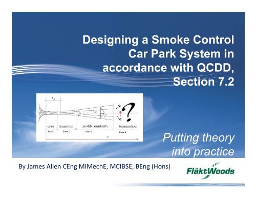
<strong>Design<strong>in</strong>g</strong> a <strong>Smoke</strong> <strong>Control</strong><br />
<strong>Car</strong> <strong>Park</strong> <strong>System</strong> <strong>in</strong><br />
accordance with QCDD,<br />
Section 7.2<br />
Putt<strong>in</strong>g theory<br />
<strong>in</strong>to practice<br />
by James Allen, Senior Applications Eng<strong>in</strong>eer<br />
By James Allen CEng MIMechE, MCIBSE, BEng (Hons)
Agenda<br />
Part 1 – Understand<strong>in</strong>g Thrust Fan capabilities<br />
• Review of velocity profile data <strong>in</strong>clud<strong>in</strong>g CAD profiles used<br />
<strong>in</strong> our design work<br />
• CFD vs measurement<br />
• Summary charts show<strong>in</strong>g maximum area coverage per fan<br />
• Modell<strong>in</strong>g jet fans <strong>in</strong> CFD (normal flow vs component<br />
velocity vectors (radial, tangential and axial velocity)
Agenda<br />
Part 2 - Considerations for both smoke clearance and smoke control<br />
• Estimation of the entra<strong>in</strong>ment effect <strong>in</strong>fluence on the extract po<strong>in</strong>t(s)<br />
• Back-flow effect caused by poor fan position<strong>in</strong>g<br />
• Effect of high <strong>in</strong>let velocities<br />
• Floor to ceil<strong>in</strong>g height <strong>in</strong>fluence<br />
• Reversibility<br />
• Incorporat<strong>in</strong>g a sensible delay period prior to operat<strong>in</strong>g fans
Agenda<br />
Part 3 – Optimal thrust fan position<strong>in</strong>g<br />
• Wall and ceil<strong>in</strong>g effects<br />
• Install<strong>in</strong>g fans <strong>in</strong> a corner<br />
• Effect of structural pillars and down-stands<br />
• Effect of <strong>in</strong>creas<strong>in</strong>g ceil<strong>in</strong>g height on the jet throw profile
INTERVAL
Agenda<br />
Part 4 – How to design for smoke control (specific to QCDD FSS-7.2)<br />
• Prediction of ceil<strong>in</strong>g jet velocity of smoke from fire plume<br />
• <strong>Smoke</strong> calculations<br />
• Mass balance calculation<br />
• Estimat<strong>in</strong>g numbers of thrust fans
Agenda<br />
Part 5 – Use of CFD<br />
• Software types<br />
• Importance of mesh<br />
• Sett<strong>in</strong>g the correct boundary conditions for the flow<br />
• Specify<strong>in</strong>g the fire source correctly<br />
• Convergence checks
Part 1<br />
Understand<strong>in</strong>g<br />
Jet fan performance
CFD modell<strong>in</strong>g of Fläkt Woods range of Thrust Fans<br />
14 profiles for Axial products 6 profiles for Induction products<br />
Knowledge of product performance<br />
(every product is different, vary<strong>in</strong>g from supplier to supplier).
Guidance on Thrust Fan selection and position<strong>in</strong>g
Guidance on Thrust Fan selection and position<strong>in</strong>g
Guidance on Thrust Fan selection and position<strong>in</strong>g
CFD modell<strong>in</strong>g translated <strong>in</strong>to CAD
Examples of CAD profiles <strong>in</strong> use
Measurement vs CFD
Measurement vs CFD
Measurement vs CFD – Plan view
Measurement vs CFD – Side view
Modell<strong>in</strong>g fans - Normal flow component vs velocity components
Modell<strong>in</strong>g Thrust Fans <strong>in</strong> CFD – Choice of mesh<br />
5cm mesh
Jet flow angle for Flakt Woods products<br />
Induction Fan<br />
Jet Fan<br />
ITF100 = 8°<br />
ITF75 = 4°<br />
ITF50 = 6°<br />
Axial fans where beams are present optimum deflector<br />
angle = 5°<br />
Flow angle of the jet from each fan product is critical to performance<br />
and position <strong>in</strong> relation to fixed objects (beams etc)
Part 2<br />
Considerations for smoke<br />
clearance and smoke control
Importance of entra<strong>in</strong>ment ratio<br />
Total flow rate = flow through the fan + entra<strong>in</strong>ment<br />
Axial fans = 4 to 6 times flow rate through the fan<br />
Induction fans = 8 to 9 times the flow rate through the fan
Importance of balanc<strong>in</strong>g Thrust fan and extract flows<br />
Thrust fans have two ma<strong>in</strong> functions – mix<strong>in</strong>g & accelerat<strong>in</strong>g air towards<br />
the extract
Importance of balanc<strong>in</strong>g Thrust fan and extract flows<br />
Thrust fans have two ma<strong>in</strong> functions – mix<strong>in</strong>g & accelerat<strong>in</strong>g air towards<br />
the extract<br />
In this example 5 fans are<br />
directed towards extract.<br />
Calculate total <strong>in</strong>duced flow that<br />
these fans provide and check that<br />
this does not exceed the extract<br />
flow rate.<br />
Consider an <strong>in</strong>stallation factor <strong>in</strong><br />
your calculations i.e.<br />
Smooth ceil<strong>in</strong>g = 0.8 to 0.9<br />
Obstructions <strong>in</strong> front of fan(s)<br />
= 0.3 to 0.6 (dependant on<br />
spac<strong>in</strong>g and depth)<br />
Installation factor is only applicable to Thrust fans
Velocity effect<br />
Velocity effect = 1 – Vc / Vf<br />
Where Vc = Velocity <strong>in</strong>duced by extract<br />
(average over car park cross-sectional<br />
area)<br />
Vf = Velocity at the outlet of the Jet fan<br />
Design velocity = required velocity /<br />
(Installation effect x velocity effect)
Importance of position<strong>in</strong>g fans at the correct spac<strong>in</strong>g<br />
Increased spac<strong>in</strong>g between Thrust Fans (>recommended limits) can<br />
mean higher extraction rates are required for smoke control.<br />
Velocity effect (1 – Vc / Vf) is reduced
Importance of position<strong>in</strong>g fans at the correct spac<strong>in</strong>g<br />
Direction of jet <strong>in</strong>duced flow<br />
Seat of fire<br />
15m spac<strong>in</strong>g<br />
Increased smoke<br />
spread upstream of<br />
fire location due to<br />
greater fan spac<strong>in</strong>g<br />
8m spac<strong>in</strong>g
Effect of high <strong>in</strong>let velocities<br />
• Too high <strong>in</strong>let velocities can caused unwanted recirculation / backflow.<br />
• Ideal <strong>in</strong>let velocity is between 1 to 2m/s.<br />
• Higher <strong>in</strong>let velocities can be designed for but need to be verified<br />
carefully us<strong>in</strong>g CFD modell<strong>in</strong>g.<br />
• Position of <strong>in</strong>lets are also important.
Reversibility<br />
zone 1 zone 2<br />
supply<br />
extract<br />
supply<br />
extract<br />
Unidirectional: 50 to 60% flow <strong>in</strong><br />
reverse. Not suitable for cont<strong>in</strong>uous<br />
operation (ok for one off)<br />
Truly symmetrical:<br />
100% <strong>in</strong> reverse<br />
Suitable for cont<strong>in</strong>uous operation
Importance of delay<strong>in</strong>g fan operation<br />
Fogg<strong>in</strong>g effect downstream of<br />
Thrust Fans due to break up of<br />
smoke layer<br />
Clear height ma<strong>in</strong>ta<strong>in</strong>ed dur<strong>in</strong>g<br />
evacuation.<br />
Delay period should be set as time taken<br />
for all occupants to evacuate (specific to<br />
each project)
Part 3<br />
Optimal Thrust fan position<strong>in</strong>g
Wall and ceil<strong>in</strong>g effects<br />
Fans <strong>in</strong> corners. Coander effect means the<br />
jet is drawn towards the wall<br />
Fans moved further away from tunnel wall<br />
the tunnel velocity <strong>in</strong>creases.<br />
Velocity effect 1-Vt / Vf is higher
Beam effects<br />
No deflector<br />
Deflector fitted<br />
Spac<strong>in</strong>g jet fans at >10 fan diameters with 5° deflection angle will m<strong>in</strong>imise<br />
effect of beam
Beam effects<br />
As much as 50% reduction <strong>in</strong><br />
Jet throw due to tightly spaced<br />
beams.<br />
Beams are 18 fan diameters<br />
apart.<br />
In this scenario use an <strong>in</strong>stallation factor of approx 0.5 when prepar<strong>in</strong>g hand<br />
calculations
Effect of floor to ceil<strong>in</strong>g height<br />
Applicable to Flakt Woods products only
Part 4<br />
How to design for smoke control<br />
(specific to QCDD FSS-7.2)
Improv<strong>in</strong>g smoke control us<strong>in</strong>g Thrust fans
<strong>Qatar</strong> civil defence requirements (FSS 7.2)<br />
• All projects <strong>in</strong> <strong>Qatar</strong> require a performance based design<br />
when design<strong>in</strong>g with Thrust Fans. Ducted can be based on 10<br />
ac/h us<strong>in</strong>g NFPA 88A and <strong>ASHRAE</strong> as reference.<br />
ref. Civil defence department m<strong>in</strong>imum standards.<br />
• 4MW or 8MW design fire dependant on whether spr<strong>in</strong>klers<br />
• 6 ac/h for pollution vent<strong>in</strong>g
<strong>Qatar</strong> civil defence requirements (FSS 7.2)<br />
• Delivery vehicles….Design fire must <strong>in</strong>crease to 10 MW or<br />
higher<br />
• Design fire must be flam<strong>in</strong>g polyurethane (Dense plastic).<br />
• Design fire considered at zone boundaries (most onerous).<br />
Justification must be provided.
<strong>Qatar</strong> civil defence requirements (FSS 7.2)<br />
• Duration of CFD simulation must be 30 m<strong>in</strong>s.<br />
• Grid size must be a maximum of 0.2m x 0.2m x 0.2m with<strong>in</strong><br />
10 metres of the fire and a maximum of 0.4m x 0.4m x 0.4m<br />
for all other areas.<br />
• Sensitivity study to be carried out to show loss of jet fan<br />
nearest fire does not impact the design
<strong>Qatar</strong> civil defence requirements (FSS 7.2)<br />
• Exhaust fans must be configured so that loss of a s<strong>in</strong>gle fan<br />
will not reduce airflow by more than 50%.<br />
• Exhaust fans must have a backup power supply such as<br />
emergency generator.<br />
• Activation of system must be automatic with manual override<br />
facility.
<strong>Smoke</strong> control – Requirements (Occupants)
<strong>Smoke</strong> control – Requirements (Fire brigade)
Fire test(s) completed by CTICM <strong>in</strong> 1995<br />
• <strong>Control</strong>led fire tests under calorimetric hood.<br />
• 1995 Peugeot 406 estate car was used.<br />
• A mean heat of combustion of 26.3MJ/kg was derived from the mass lost and<br />
energy released dur<strong>in</strong>g first 35m<strong>in</strong>s.<br />
Ref. CTICM report 2001, INC 01/410b DJ/NB.
Maximum measured heat release rate<br />
Peak heat<br />
release<br />
around 8MW<br />
• Graph shows peak heat release rate from tests performed 1998<br />
to 2001 (CTICM, France). No spr<strong>in</strong>klers <strong>in</strong>volv<strong>in</strong>g 3 cars (Renault<br />
Laguna).
More recent research by BRE<br />
• 16MW with no spr<strong>in</strong>klers! (3 car fire) – test 1<br />
•7MW with spr<strong>in</strong>klers but after 50-60 m<strong>in</strong>utes <strong>in</strong>to fire – test 2<br />
• 5MW s<strong>in</strong>gle car (medium sized) after 40 m<strong>in</strong>utes<br />
• 4MW s<strong>in</strong>gle car (Multi purpose vehicle) after 40 m<strong>in</strong>utes<br />
SLIDE 47
Why are we see<strong>in</strong>g an <strong>in</strong>crease <strong>in</strong> fire size<br />
Source: http://www.plasticsconverters.eu<br />
• Increased use of plastics to reduce weight and capital cost of production.<br />
• Vehicles generally larger - more plastics required to reduce weight<br />
i.e. plastic car body panels.
Current Standards / Guidance<br />
QCDD FSS7.2 and BS7346 Part 7 recommends:<br />
• 4 MW for s<strong>in</strong>gle car (spr<strong>in</strong>klers)<br />
• 8 MW for two cars (no spr<strong>in</strong>klers) however latest research shows it can be<br />
much higher<br />
Neither QCDD FSS7.2 or BS7346 Part 7 <strong>in</strong>forms the reader of how to design a smoke<br />
control system. Only performance objectives and guidance are given.
Tools available to the designer<br />
Three categories: EMPERICAL, ZONE MODELS, CFD<br />
M = 0.188 x P x Y 3/2<br />
HAND CALCULATION (EMPERICAL):<br />
Very simple<br />
Applicable to limited range of conditions<br />
Thomas, Alpert et al<br />
CFAST. Ozone<br />
ZONE MODELS:<br />
Simple and fast to use<br />
Application limits def<strong>in</strong>ed<br />
Multi compartments<br />
CFD MODELS:<br />
Complex<br />
Expert knowledge<br />
Most accurate but costly<br />
ANSYS, FLUENT, FDS, Flosim
How to design for smoke control - Design steps<br />
1. Determ<strong>in</strong>e design fire size accord<strong>in</strong>g to whether or not there are spr<strong>in</strong>klers –SLIDE<br />
2. Determ<strong>in</strong>e zone layout, at least one extract and one supply po<strong>in</strong>t per zone. Decide on<br />
general flow distribution and smoke travel distance<br />
3. Calculate the velocity of smoke at required control distance (10 metres upstream)<br />
4. Calculate the m<strong>in</strong>imum design flow rate for smoke control<br />
5. Calculate the mass-flow of smoke and smoke temperature at the fire<br />
6. Calculate mass-flow towards the extract<br />
7. Calculate density downstream<br />
8. Calculate the extract flow rate required<br />
9. Calculate Thrust fan quantity<br />
10. CFD analysis
Steps 1 and 2: Fire size and ventilation configuration<br />
Step 2<br />
Step 2<br />
Step 1<br />
Step 2<br />
Step 2
Step 3: <strong>Smoke</strong> control calculations<br />
SMOKE VELOCITY (Vs)<br />
energy from fire<br />
moves smoke<br />
Jet Thrust Fan<br />
>18ms -1 velocity<br />
JETFAN<br />
1.0 ms -1<br />
entra<strong>in</strong>ed air flow<br />
CAR FIRE – 3MW<br />
10 metres<br />
Step 3: V ceil<strong>in</strong>g jet =0.195*Q 1/3 *h 1/2 /r 5/6 (Albert et al)<br />
1 car = 0.6m/s at 10 metres from the fire (3 metres high car park)<br />
2 cars = 1 m/s at 10 metres from the fire (3 metres high car park)
Step 4: M<strong>in</strong>imum design flow rate<br />
Design flow rate (Qd) = (Design width x height) x M<strong>in</strong> velocity<br />
M<strong>in</strong> design velocity = V ceil<strong>in</strong>g jet / (<strong>in</strong>stallation effect x velocity effect)<br />
Where:<br />
Velocity effect = 1 – V ceil<strong>in</strong>g jet / V jetfan<br />
Step 3<br />
Design width varies accord<strong>in</strong>g to scenario but suggested start<strong>in</strong>g po<strong>in</strong>t is 28 metres<br />
(approx. 2 roadway widths + 2 car park spaces length).<br />
Typical <strong>in</strong>stallation factors:<br />
• 0.9 with pillars and no down-stand beams<br />
• 0.7 with pillars and down-stand beams where the spac<strong>in</strong>g of beams > 18 fan diameters<br />
• 0.5 with pillars and down-stand beams where the spac<strong>in</strong>g of beams
<strong>Smoke</strong> calculations<br />
The rema<strong>in</strong><strong>in</strong>g calculation methods (steps 5 to 9) are presented <strong>in</strong> a technical<br />
paper. Please contact your Fläkt Woods representative for more <strong>in</strong>formation.
Clos<strong>in</strong>g statement<br />
The method presented, developed by Mr J. Allen, has been proven to work on<br />
a number of projects however it is still relatively new. It is not presented<br />
with<strong>in</strong> any standards however a technical paper has been written. The<br />
technical paper will soon be available through the Fläkt Woods website.<br />
Further research and development is needed to f<strong>in</strong>e tune the approach.<br />
As stated by Dr H. P. Morgan, co-author of ‘Extend<strong>in</strong>g the pr<strong>in</strong>ciples of<br />
Impulse ventilation <strong>in</strong> tunnels to apply to smoke control <strong>in</strong> car parks’:<br />
“ If the <strong>in</strong>duced bulk air volume flow is greater than the extract volume flow rate, the<br />
discrepancy between what is be<strong>in</strong>g “pushed” towards the exhaust and what is be<strong>in</strong>g<br />
removed must somehow travel back past the fans to become available at the fan <strong>in</strong>lets.<br />
This can either take the form of a recirculation pattern throughout the car park, caus<strong>in</strong>g<br />
smoke to affect the areas <strong>in</strong>tended to be kept clear, or it can take the form of a local<br />
recirculation at each fan, which would have less of an adverse effect on system<br />
performance. The significance of these recirculation patterns cannot be assessed by<br />
zone- model methods but should be revealed by CFD modell<strong>in</strong>g”
Part 5<br />
Us<strong>in</strong>g Computational Fluid Dynamics<br />
(CFD)
Use of CFD – Air distribution & smoke control
CFD Software types<br />
CFX, Fluent, Flosim, Phoenics - RANS<br />
FDS, CFX - LES<br />
CFX - DES
Is all CFD software fit for purpose<br />
ITF 75 – Model <strong>in</strong> FDS5<br />
Image courtesy of <strong>in</strong>dependent fire consultant<br />
ITF 75 – Model <strong>in</strong> CFX (SST turbulence model)<br />
20cm mesh!
Is all CFD software fit for purpose<br />
ITF 75 – Model <strong>in</strong> FDS5<br />
Images courtesy of <strong>in</strong>dependent fire consultant<br />
20cm mesh!
Is all CFD software fit for purpose<br />
Images courtesy of ANSYS<br />
• CFX (RANS based) us<strong>in</strong>g SST turbulence model predicts<br />
separation and reattachment of flow where as the<br />
standard K-e model fails to capture this flow entirely
Is all software fit for purpose<br />
Conclusion:<br />
• FDS5 severely over predicts the performance of jet fans.<br />
This is due to turbulence model used (no separation and<br />
reattachment)<br />
• FDS6 is much better (due to new turbulence model) but<br />
under-predicts flow. Conservative estimate<br />
• CFX (RANS based model) provides the closest match to<br />
test data provid<strong>in</strong>g appropriate mesh sizes are used AND<br />
suitable turbulence model (SST is best at simulat<strong>in</strong>g<br />
separation and reattachment of flow)
‘Inert’ volumetric heat source model<br />
• Volume of heat release must be specified by user<br />
• Verification of volume essential prior to runn<strong>in</strong>g simulations<br />
• Uniform distribution of heat and smoke<br />
• Simple / less computationally expensive<br />
• Ideal for large complex spaces i.e. car parks<br />
• Only suitable for well ventilated fires<br />
• Can be used with any radiation sub model<br />
• Realistic temperatures and flow phenomenon are achievable
Us<strong>in</strong>g the correct fuel area / volume <strong>in</strong> CFD models<br />
• Simplest method is volumetric heat source<br />
• Volume of source needs careful consideration<br />
Incorrectly def<strong>in</strong>ed<br />
heat source volume<br />
Flame height too low<br />
Layer depth too shallow<br />
More realistic heat<br />
source volume<br />
Flame height & layer depth more consistent with empirical correlations
Volumetric heat source recommendations<br />
• Fire power density <strong>in</strong> the range from 500 kW/m³ to 1000 kW/m³<br />
Depend<strong>in</strong>g on application and geometry.<br />
• Experimentation is required to reach realistic results.<br />
• Comparison should be made aga<strong>in</strong>st calculations and / or<br />
experiment <strong>in</strong> terms of both flame temperature and flame height<br />
REALISTIC RESULTS<br />
OBTAINED SEVERAL<br />
METRES FROM THE<br />
SOURCE.<br />
See ‘Treatment of fire<br />
source <strong>in</strong> CFD’ , R. Yan, V.<br />
Cheng, R.Y<strong>in</strong>, 2003
Inert models - Volumetric heat source<br />
• Vitally important to correctly def<strong>in</strong>e the fire volume<br />
• Good reference is ‘Treatment of fire source <strong>in</strong> CFD’ , R. Yan, V. Cheng,<br />
R.Y<strong>in</strong>, 2003<br />
Max: 800 -1300 deg C<br />
Average: 400 – 500 deg C<br />
Fluid volume<br />
estimated by<br />
solver
React<strong>in</strong>g combustion model<br />
• Aims to predict heat distribution <strong>in</strong> the flam<strong>in</strong>g region<br />
• Area of fuel source must be specified by the user<br />
• Suited to simpler geometries as computationally more expensive<br />
• Significantly <strong>in</strong>creases timescale from days to weeks<br />
• The only choice for under-ventilated fires<br />
• Heat and smoke distribution non-uniform<br />
• Can be used with any radiation sub model
Example of a react<strong>in</strong>g combustion model<br />
• Def<strong>in</strong>ed as an ‘area’ source of combustible material<br />
• CFX calculates the mix<strong>in</strong>g of gaseous fuel with air and assumes the<br />
combustion rate is <strong>in</strong>f<strong>in</strong>itely fast with respect to turbulent mix<strong>in</strong>g<br />
• The distribution of combustion <strong>in</strong> the fire plume is predicted
Estimation of smoke production<br />
• Quantity of smoke and tox<strong>in</strong>s prescribed by the user as a function of the mass<br />
of combustible products.<br />
• Refer to smoke yield factors for common materials <strong>in</strong> fire eng<strong>in</strong>eer<strong>in</strong>g<br />
literature. Source: C.P. Bankston, B.T. Z<strong>in</strong>n, R.F.Browner, and E.A. Powel, Comb.<br />
and Flame, 41, 273 (1981).<br />
• Polyurethane fuel > 10 to 11% of the mass of combustible products. This falls<br />
mid way <strong>in</strong> the range which is typically 0.01 to 0.20 for flam<strong>in</strong>g combustion.<br />
• Characteristic heat of combustion (H c ) – typically 24 to 26 MJ/Kg.
Visibility through smoke<br />
Light reflect<strong>in</strong>g or light emitt<strong>in</strong>g correlations developed through scientific study.<br />
S [m] = K / (α [m 2 /kg] x mass fraction [kg/kg] x density [kg/m³] )<br />
Ref. Klote J.,J. Mike, Pr<strong>in</strong>ciples of <strong>Smoke</strong> management, 2002<br />
Where:<br />
K = proportionality constant<br />
Illum<strong>in</strong>at<strong>in</strong>g signs K = 8<br />
Reflect<strong>in</strong>g signs and build<strong>in</strong>g components K = 3<br />
α = specific ext<strong>in</strong>ction coefficient (8700 [m 2 /kg] flam<strong>in</strong>g combustion
Boundary and <strong>in</strong>itial flow specification<br />
Typical examples <strong>in</strong>clude:<br />
• Initial flows present prior to the simulation (i.e. w<strong>in</strong>d pressures)<br />
• Flows <strong>in</strong> / out through doors, w<strong>in</strong>dows, open<strong>in</strong>gs, vents or mechanical <strong>in</strong>let / extract<br />
systems<br />
• Change of momentum and / or energy <strong>in</strong> simplified representations of mechanical<br />
systems such as jet fans.<br />
• Energy transfer (<strong>in</strong> the form of heat) at (to / from) walls.<br />
• Sources of mass, momentum and / or energy, e.g. at the fire, or through the release of a<br />
suppressant.
Importance of wall boundary specification<br />
Adiabatic walls<br />
Heat flux of 25W/m²/K<br />
+ fixed temp<br />
The CFD user specifies how heat transfer is to be modelled at the walls:<br />
• Assume nil heat transfer, i.e. an adiabatic wall.<br />
<strong>Smoke</strong> layer is lower!<br />
• Assume a constant wall temperature, lead<strong>in</strong>g to maximum rates of heat transfer.<br />
Suggestion use a heat flux - typically 25W/m²/K with a fixed temperature on the other<br />
side of the wall (Ref. EN191-1-2)<br />
•Adiabatic wall condition should be used with caution s<strong>in</strong>ce less smoke is predicted at<br />
lower levels and to faster smoke propagation towards extract.
Importance of the mesh size<br />
• Mesh resolution can have a significant affect on accuracy of predictions<br />
BOTH for RANS and LES models. LES models can be particularly sensitive.<br />
0.25m<br />
0.1m (fire region)<br />
0.40m<br />
0.2m (fire region)<br />
0.50m<br />
0.225m<br />
(fire region)
Importance of the mesh size<br />
• Trade off between accuracy and run time.<br />
• Broad range of mesh sizes can be used – the user should ideally carryout a grid sensitivity check.<br />
• Important flow regions such as fans and <strong>in</strong>lets / outlets should ideally rema<strong>in</strong> constant us<strong>in</strong>g best<br />
practice guidel<strong>in</strong>es.<br />
• Inflation layers should ideally be used at wall <strong>in</strong>terfaces although it is recognised this is not available<br />
<strong>in</strong> all software.<br />
• F<strong>in</strong>er meshes should be used <strong>in</strong> the fire region to capture the complex heat exchange and flow<br />
phenomenon. Typically 0.1 to 0.2m will normally suffice.
Importance of mesh aspect ratio<br />
• Mesh aspect ratio can have a significant affect on accuracy of predictions<br />
BOTH for RANS and LES models. However LES can be more sensitive to large<br />
variations<br />
• COX and Kumar recommend 1 to 50 as max aspect ratio (RANS)<br />
• Lower aspect ratios close to the fire (1:1)<br />
• FDS models require much lower ratios, typically 1:3 (>timescale)
Use of <strong>in</strong>flation layers <strong>in</strong> ANSYS CFX<br />
F<strong>in</strong>er mesh <strong>in</strong> fire region<br />
Inflation layer at ceil<strong>in</strong>g
Effect of <strong>in</strong>flation layer on smoke spread
Effect of <strong>in</strong>flation layer on smoke spread
Effect of <strong>in</strong>flation layer on smoke spread
Effect of <strong>in</strong>flation layer on smoke spread
Effect of <strong>in</strong>flation layer on smoke spread
React<strong>in</strong>g Models: Flammability<br />
Mass fraction<br />
O2 = 0.12
React<strong>in</strong>g Models: Comparisons – Oxygen mass fraction<br />
Modified<br />
code with<br />
simple<br />
ext<strong>in</strong>ction<br />
model<br />
Burn<strong>in</strong>g still takes place<br />
right up to po<strong>in</strong>t where<br />
there is no oxygen left<br />
which is not physically<br />
valid<br />
without<br />
ext<strong>in</strong>ction<br />
model
Comparisons - Temperature<br />
Peak temperature is<br />
realistic.<br />
Modified<br />
code with<br />
simple<br />
ext<strong>in</strong>ction<br />
model<br />
Flame ext<strong>in</strong>ction<br />
corresponds with po<strong>in</strong>t<br />
where CO.mf reaches<br />
approx 0.12.<br />
Without<br />
ext<strong>in</strong>ction<br />
model<br />
Peak temperature<br />
reaches unrealistic<br />
value as the fire should<br />
have stopped burn<strong>in</strong>g.
Example of convergence checks
Check list<br />
1. The fuel area (or volume <strong>in</strong> the case of heat source method) should be sized to yield<br />
realistic average and peak temperatures. Maximum temperature should be shown <strong>in</strong> the<br />
report.<br />
2. Maximum gas temperatures should be <strong>in</strong> the range 800 to 1300 C. Maximum<br />
temperatures should not exceed 1300 C.<br />
3. An appropriate value for the Characteristic heat of combustion should be used. Usually<br />
between 24 to 26 MJ/Kg.<br />
4. Soot yield should be specified <strong>in</strong> the report. 0.1 is normally specified for polyurethane fuel<br />
(FSS7.2 – 2.3).<br />
5. Ceil<strong>in</strong>g and outer walls should have heat transfer model applied rather than adiabatic (no<br />
heat loss assumption). Suggested value for heat transfer is 25kW/m²/K (EN191-1-2).<br />
6. Mass, momentum and energy conservation should be demonstrated.<br />
7. Sensitivity to the mesh size chosen should be demonstrated.<br />
8. Residual plots should be <strong>in</strong>cluded (where available) to show that the time step value<br />
chosen is suitable. Transient time steps of typically 0.25 to 0.5 seconds are usually required<br />
to achieve reasonable convergence.