Variable Area Flow Meters - F Series, Ideal For ... - Temp-Press Inc
Variable Area Flow Meters - F Series, Ideal For ... - Temp-Press Inc
Variable Area Flow Meters - F Series, Ideal For ... - Temp-Press Inc

Create successful ePaper yourself
Turn your PDF publications into a flip-book with our unique Google optimized e-Paper software.
PDF Published January 17, 2011<br />
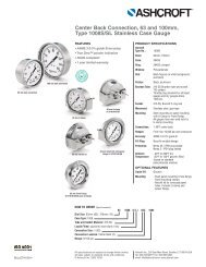
<strong>Variable</strong> <strong>Area</strong><br />
<strong>Flow</strong> <strong>Meters</strong><br />
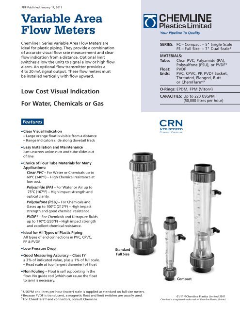
Chemline F <strong>Series</strong> <strong>Variable</strong> <strong>Area</strong> <strong>Flow</strong> <strong>Meters</strong> are<br />
ideal for plastic piping. They provide a combination<br />
of accurate visual flow rate measurement and clear<br />
flow indication from a distance. Optional limit<br />
switches allow the units to signal a low or high flow<br />
alarm. An optional flow transmitter provides a<br />
4 to 20 mA signal output. These flow meters must<br />
be installed vertically with flow upward.<br />
Low Cost Visual Indication<br />
<strong>For</strong> Water, Chemicals or Gas<br />
Your Pipeline To Quality<br />
SERIES:<br />
FC – Compact – 5" Single Scale<br />
FS – Full Size – 7" Dual Scale 1<br />
MATERIALS:<br />
Tube: Clear PVC, Polyamide (PA),<br />
Polysulfone (PSU), or PVDF 2<br />
Float: PVDF<br />
Ends: PVC, CPVC, PP, PVDF Socket,<br />
Threaded, Flanged, Butt<br />
or ChemFlare TM3<br />
O-Rings: EPDM, FPM (Viton ® )<br />
CAPACITIES: Up to 220 USGPM<br />
(50,000 litres per hour)<br />
Features<br />
● Clear Visual Indication<br />
– Large orange float is visible from a distance<br />
– Range indicators slide along dovetail track<br />
● Easy Installation and Maintenance<br />
Just unscrew union nuts and tube slides out<br />
of line<br />
● Choice of Four Tube Materials for Many<br />
Applications:<br />
Clear PVC – <strong>For</strong> Water or Chemicals up to<br />
60ºC (140ºF) – High Chemical resistance at<br />
low cost.<br />
Polyamide (PA) – <strong>For</strong> Water or Air up to<br />
75ºC (167ºF) – High impact strength and<br />
optical clarity.<br />
Polysulfone (PSU) – <strong>For</strong> Chemicals and<br />
Gases up to 100ºC (212ºF) – High impact<br />
strength and good chemical resistance.<br />
PVDF 2 – <strong>For</strong> Chemicals and Ultrapure fluids<br />
up to 110ºC (230ºF) – High impact strength<br />
and excellent chemical resistance.<br />
● <strong>Ideal</strong> for All Types of Plastic Piping<br />
All types of end connections in PVC, CPVC,<br />
PP & PVDF<br />
● Low <strong>Press</strong>ure Drop<br />
● Good Measuring Accuracy – Class IV<br />
± 3% of indicated value, plus ± 1% of full scale.<br />
– Read scale at top (largest diameter) of float<br />
● Non Fouling – Float is self supporting in the<br />
flow. No guide rod (which can cause the float<br />
to jam) is necessary.<br />
Standard<br />
Full Size<br />
Compact<br />
1 USGPM and litres per hour (water) scale is supplied as standard on full size meters.<br />
2 Because PVDF is translucent, a magnetic float and limit switches are usually used.<br />
3 <strong>For</strong> ChemFlare TM end connectors, consult Chemline.<br />
01/11 ©Chemline Plastics Limited 2011<br />
Chemline is a registered trade mark of Chemline Plastics Limited
<strong>Variable</strong> <strong>Area</strong> <strong>Flow</strong> <strong>Meters</strong><br />
NOTES:<br />
PVDF flow meters are available in all sizes. Change third letter in item number to K.<br />
1<br />
△P = <strong>Press</strong>ure loss through flow meter with water at 20ºC (68ºF).<br />
2 Dimension L is for PVC Socket ends.<br />
FC SERIES – COMPACT SIZE – 5" SCALE<br />
Single USGPM (water) scale is supplied standard.<br />
End<br />
Item Number <strong>Flow</strong> Range (water) Dimensions (inches) <strong>Press</strong>ure<br />
Conn. PVC Polyamide Polysulfone<br />
Drop (psi) 1<br />
Size Tube Tube Tube<br />
USGPM Litres per hour A L 2 D Water Air<br />
FCA00020 FCT00020 FCP00020 0.0132 – 0.106 3 – 24 6.50 8.2 1.38 0.05 0.07<br />
3/8"<br />
FCA00060 FCT00060 FCP00060 0.022 – 0.264 5 – 60 6.50 8.2 1.38 0.05 0.07<br />
FCA00100 FCT00100 FCP00100 0.04 – 0.44 10 – 100 6.50 8.2 1.38 0.05 0.07<br />
FCA00250 FCT00250 FCP00250 0.11 – 1.10 25 – 250 6.50 8.2 1.38 0.05 0.07<br />
FCA00051 FCT00051 FCP00051 0.02 – 0.22 5 – 50 6.69 8.7 1.69 0.04 0.06<br />
1/2"<br />
FCA00151 FCT00151 FCP00151 0.07 – 0.66 15 – 150 6.69 8.7 1.69 0.04 0.06<br />
FCA00251 FCT00251 FCP00251 0.11 – 1.10 25 – 250 6.69 8.7 1.69 0.04 0.06<br />
FCA00401 FCT00401 FCP00401 0.18 – 1.76 40 – 400 6.69 8.7 1.69 0.04 0.06<br />
FCA00152 FCT00152 FCP00152 0.07 – 0.66 15 – 150 7.28 9.6 2.09 0.09 0.12<br />
3/4"<br />
FCA00402 FCT00402 FCP00402 0.22 – 1.76 40 – 400 7.28 9.6 2.09 0.09 0.12<br />
FCA00602 FCT00602 FCP00602 0.26 – 2.64 60 – 600 7.28 9.6 2.09 0.09 0.12<br />
FCA01002 FCT01002 FCP01002 0.44 – 4.40 100 – 1,000 7.28 9.6 2.09 0.09 0.12<br />
FCA00253 FCT00253 FCP00253 0.11 – 1.10 25 – 250 7.87 10.5 2.36 0.09 0.12<br />
1"<br />
FCA00403 FCT00403 FCP00403 0.18 – 1.76 40 – 400 7.87 10.5 2.36 0.09 0.12<br />
FCA01003 FCT01003 FCP01003 0.44 – 4.40 100 – 1,000 7.87 10.5 2.36 0.09 0.12<br />
FCA01503 FCT01503 FCP01503 0.66 – 6.60 150 – 1,500 7.87 10.5 2.36 0.09 0.12<br />
FS SERIES – STANDARD FULL SIZE – 7" SCALE<br />
Dual USGPM (water) and litres per hour scales are supplied standard.<br />
End<br />
Item Number <strong>Flow</strong> Range (water) Dimensions (inches) <strong>Press</strong>ure<br />
Conn. PVC Polyamide Polysulfone<br />
Drop (psi) 1<br />
Size Tube Tube Tube<br />
USGPM Litres per hour A L 2 D Water Air<br />
FSA00150 FST00150 FSP00150 0.07 – 0.66 15 – 150 13.78 16.3 2.36 0.18 0.23<br />
1"<br />
FSA00300 FST00300 FSP00300 0.13 – 1.32 30 – 300 13.78 16.3 2.36 0.18 0.23<br />
FSA00600 FST00600 FSP00600 0.26 – 2.64 60 – 600 13.78 16.3 2.36 0.18 0.23<br />
FSA01000 FST01000 FSP01000 0.44 – 4.40 100 – 1,000 13.78 16.3 2.36 0.18 0.23<br />
1-1/4"<br />
FSA01500 FST01500 FSP01500 0.66 – 6.60 150 – 1,500 13.78 16.6 2.83 0.18 0.23<br />
FSA02500 FST02500 FSP02500 1.10 – 11.00 250 – 2,500 13.78 16.6 2.83 0.18 0.23<br />
1-1/2"<br />
FSA02000 FST02000 FSP02000 0.88 – 8.80 200 – 2,000 13.78 16.8 3.27 0.18 0.23<br />
FSA03000 FST03000 FSP03000 1.32 – 13.20 300 – 3,000 13.78 16.8 3.27 0.18 0.23<br />
FSA04000 FST04000 FSP04000 1.76 – 17.60 400 – 4,000 13.78 17.2 4.06 0.32 0.39<br />
2" FSA06000 FST06000 FSP06000 2.64 – 26.40 600 – 6,000 13.78 17.2 4.06 0.32 0.39<br />
FSA10000 FST10000 FSP10000 4.40 – 44.00 1,000 – 10,000 13.78 17.2 4.06 0.32 0.39<br />
FSA15000 FST15000 FSP15000 6.60 – 66.00 1,500 – 15,000 13.78 17.7 4.80 0.49 0.58<br />
2-1/2" FSA25000 FST25000 FSP25000 11.00 – 110.00 2,500 – 25,000 13.78 17.7 4.80 0.49 0.58<br />
FSA50000 FST50000 FSP50000 44.00 – 220.00 10,000 – 50,000 13.78 17.7 4.80 0.49 0.58<br />
CONVERSION CHART – FLOW UNITS<br />
From<br />
To<br />
m 3 /hr<br />
litres/hr<br />
USGPM<br />
ImpGPM<br />
ft 3 /min<br />
m 3 /hr<br />
1<br />
1000<br />
4.4029<br />
3.6662<br />
0.5886<br />
litres/hr<br />
0.001<br />
1<br />
.004403<br />
.003666<br />
.000589<br />
USGPM<br />
0.2271<br />
227.12<br />
1<br />
0.8327<br />
0.1337<br />
ImpGPM<br />
0.2728<br />
272.77<br />
1.2009<br />
1<br />
0.1605<br />
ft 3 /min<br />
1.6990<br />
1699<br />
7.4806<br />
6.2289<br />
1<br />
†Values based on water at 20ºC (68ºF).
<strong>Variable</strong> <strong>Area</strong> <strong>Flow</strong> <strong>Meters</strong><br />
6<br />
5<br />
4<br />
8<br />
1<br />
2<br />
A<br />
B<br />
L<br />
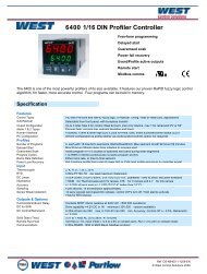
PARTS<br />
▲ Recommended Spare Parts<br />
No. Part Pcs. Materials<br />
1 Tube 1 Polyamide (PA),<br />
Polysulfone (PSU),<br />
Clear PVC, PVDF<br />
2 Float 1 PVDF (standard<br />
or magnetic)<br />
3 Lower Float Stop 1 PVDF<br />
4 Upper Float Stop 1 PVDF<br />
5 Union Nut 2 PVC, PPG, PVDF<br />
6 End Connector 2 PVC, CPVC, PP or<br />
PVDF<br />
7▲ O-Rings 2 EPDM, FPM(Viton ® )<br />
8▲ Range Indicator 2 ABS<br />
ACCESSORIES<br />
● Limit Switches – One switch for both<br />
maximum or minimum. A magnetic float is<br />
required.<br />
● Switch Ratings – P (max) = 10 VA,<br />
E (max) = 470VAC, I (max) = 0.5A<br />
● Throttling Valve for flow control<br />
● 4–20 mA Output Signal Unit must be factory<br />
calibrated for specific service<br />
OPTIONS<br />
● Custom Direct Reading Scale for services<br />
other than water<br />
● Alternate O-Rings – ie. FPM (Viton<br />
® )<br />
● End Size Reduction – Accuracy is not<br />
significantly affected by end reduction<br />
● Other Ends – Threaded, socket or flanged<br />
end connections in PVC, CPVC, PP or PVDF.<br />
Butt ends in PP or PVDF.<br />
3<br />
7<br />
D<br />
MAXIMUM WORKING PRESSURES AND TEMPERATURE RANGES<br />
Construction (‡ = Optional Materials)<br />
Tube O-Rings Union Nuts Ends<br />
PVC<br />
Polyamide (PA)<br />
Polyamide (PA)<br />
Polysulfone (PSU)<br />
Polysulfone (PSU)<br />
EPDM<br />
EPDM<br />
EPDM<br />
EPDM<br />
EPDM<br />
PVC<br />
PVC<br />
PPG‡<br />
PVC<br />
PPG‡<br />
PVC<br />
PVC<br />
PP or CPVC‡<br />
PVC<br />
PP or CPVC‡<br />
PVDF FPM(Viton ® ) PVDF PVDF<br />
Maximum<br />
<strong>Press</strong>ure 2<br />
150 psi<br />
150 psi<br />
150 psi<br />
150 psi<br />
150 psi<br />
150 psi<br />
2 150 psi is not recommended at maximum temperatures. Consult Chemline.<br />
<strong>Temp</strong>erature Range<br />
0 to 60ºC (32 to 140ºF)<br />
0 to 60ºC (32 to 140ºF)<br />
0 to 75ºC (32 to 167ºF)<br />
0 to 60ºC (32 to 140ºF)<br />
0 to 90ºC (32 to 194ºF)<br />
–40 to 110ºC (–40 to 230ºF)<br />
<strong>Flow</strong> Meter Sizing – Liquid <strong>Flow</strong><br />
Standard Scale values are for clean water flow at 20ºC (68ºF). <strong>For</strong> liquids with densities and viscosities similar to water (ie. specific gravity of<br />
1.0 and viscosities between 0.5 cP and 1.3 cP) the standard water scale will be accurate enough.<br />
The table below shows correction factors to be applied for liquids with specific gravities other then 1.0. Multiply the correction factor by the<br />
water scale value to obtain actual flow rate. Example: <strong>For</strong> a liquid of specific gravity of 1.66, the correction factor is 0.740. <strong>For</strong> water flow<br />
range of 100 to 1000 litres/hr, corrected range becomes 74 to 740 litres/hr. Viscosity should be between 0.5 cP and 1.3 cP for standard scales<br />
to be accurate.<br />
<strong>For</strong> "sizing" liquid flows ie. determining actual flow range of a tube, please advise the chemical name, concentration, temperature, specific<br />
gravity and viscosity. Custom direct reading scales in any units are available special order.<br />
SCALE CORRECTION FACTORS – FOR LIQUIDS WITH SPECIFIC GRAVITIES OTHER THAN 1.00<br />
Specific .00 .01 .02 .03 .04 .05 .06 .07<br />
Gravity<br />
Scale Correction Factor<br />
0.4<br />
0.5<br />
0.6<br />
0.7<br />
0.8<br />
0.9<br />
1.0<br />
1.1<br />
1.2<br />
1.3<br />
1.4<br />
1.5<br />
1.6<br />
1.7<br />
1.8<br />
1.9<br />
2.0<br />
1.647<br />
1.462<br />
1.326<br />
1.220<br />
1.134<br />
1.062<br />
1.000<br />
0.947<br />
0.900<br />
0.858<br />
0.820<br />
0.787<br />
0.756<br />
0.728<br />
0.701<br />
0.677<br />
0.654<br />
1.626<br />
1.447<br />
1.316<br />
1.211<br />
1.125<br />
1.055<br />
0.994<br />
0.943<br />
0.895<br />
0.854<br />
0.818<br />
0.784<br />
0.754<br />
0.726<br />
0.699<br />
0.674<br />
0.652<br />
1.605<br />
1.433<br />
1.304<br />
1.202<br />
1.117<br />
1.048<br />
0.988<br />
0.936<br />
0.891<br />
0.850<br />
0.814<br />
0.781<br />
0.751<br />
0.723<br />
0.696<br />
0.672<br />
0.650<br />
1.585<br />
1.418<br />
1.292<br />
1.192<br />
1.111<br />
1.042<br />
0.982<br />
0.932<br />
0.887<br />
0.846<br />
0.810<br />
0.778<br />
0.748<br />
0.720<br />
0.694<br />
0.669<br />
0.648<br />
1.565<br />
1.404<br />
1.282<br />
1.183<br />
1.104<br />
1.035<br />
0.978<br />
0.927<br />
0.883<br />
0.842<br />
0.806<br />
0.776<br />
0.745<br />
0.717<br />
0.691<br />
0.667<br />
0.646<br />
1.548<br />
1.391<br />
1.271<br />
1.175<br />
1.096<br />
1.030<br />
0.972<br />
0.923<br />
0.878<br />
0.838<br />
0.803<br />
0.773<br />
0.742<br />
0.714<br />
0.689<br />
0.665<br />
0.644<br />
1.529<br />
1.377<br />
1.259<br />
1.167<br />
1.089<br />
1.024<br />
0.967<br />
0.917<br />
0.874<br />
0.835<br />
0.800<br />
0.770<br />
0.740<br />
0.712<br />
0.686<br />
0.663<br />
0.641<br />
1.513<br />
1.364<br />
1.250<br />
1.157<br />
1.082<br />
1.017<br />
0.962<br />
0.913<br />
0.870<br />
0.831<br />
0.797<br />
0.767<br />
0.737<br />
0.709<br />
0.684<br />
0.661<br />
0.604<br />
.08<br />
1.495<br />
1.351<br />
1.239<br />
1.149<br />
1.075<br />
1.011<br />
0.956<br />
0.909<br />
0.866<br />
0.827<br />
0.794<br />
0.764<br />
0.734<br />
0.706<br />
0.682<br />
0.658<br />
0.637<br />
.09<br />
1.479<br />
1.339<br />
1.229<br />
1.142<br />
1.068<br />
1.005<br />
0.951<br />
0.904<br />
0.862<br />
0.824<br />
0.791<br />
0.759<br />
0.730<br />
0.704<br />
0.679<br />
0.657<br />
0.636
<strong>Variable</strong> <strong>Area</strong> <strong>Flow</strong> <strong>Meters</strong><br />
<strong>Flow</strong> Meter Sizing – Gas <strong>Flow</strong><br />
FLOW RANGES FOR AIR – AT STANDARD CONDITIONS (atmospheric pressure 14.7 psia/20 O C).<br />
FC SERIES – COMPACT SIZE – 5" SCALE<br />
FS SERIES – STANDARD FULL SIZE – 7" SCALE<br />
<strong>Flow</strong> Meter<br />
Item No.<br />
FCT00020<br />
FCT00060<br />
FCT00100<br />
FCT00250<br />
FCT00051<br />
FCT00151<br />
FCT00251<br />
FCT00401<br />
FCT00152<br />
FCT00402<br />
FCT00602<br />
FCT01002<br />
FCT00253<br />
FCT00403<br />
FCT01003<br />
FCT01503<br />
Normal<br />
m 3 /hr<br />
0.2 – 1.0<br />
0.2 – 2.5<br />
0.6 – 3.6<br />
0.5 – 9.0<br />
0.4 – 2.8<br />
0.8 – 6.2<br />
0.9 – 9.5<br />
2.0 – 15.0<br />
0.5 – 5.5<br />
2.0 – 14.0<br />
2.5 – 22.0<br />
4.0 – 34.0<br />
1.0 – 8.0<br />
2.0 – 14.0<br />
4.0 – 34.0<br />
5.0 – 50.0<br />
Standard<br />
CFM<br />
0.1 – 0.6<br />
0.1 – 1.5<br />
0.4 – 2.1<br />
0.3 – 5.3<br />
0.2 – 1.6<br />
0.5 – 3.6<br />
0.5 – 5.6<br />
1.2 – 8.8<br />
0.3 – 3.2<br />
1.2 – 8.2<br />
1.5 – 12.9<br />
2.4 – 20.0<br />
0.6 – 4.7<br />
1.2 – 8.2<br />
2.4 – 20.0<br />
2.9 – 29.4<br />
<strong>Flow</strong> Meter<br />
Item No.<br />
FST00150<br />
FST00300<br />
FST00600<br />
FST01000<br />
FST01500<br />
FST02000<br />
FST02500<br />
FST03000<br />
FST04000<br />
FST06000<br />
FST10000<br />
FST15000<br />
FST25000<br />
FST50000<br />
Normal<br />
m 3 /hr<br />
0.7 – 5.5<br />
1– 10<br />
2.5 – 20<br />
4– 34<br />
5– 50<br />
8.5 – 76<br />
8– 70<br />
10 – 90<br />
14 – 125<br />
22 – 190<br />
35 – 300<br />
50 – 500<br />
80 – 720<br />
400 – 1,500<br />
Standard<br />
CFM<br />
0.4 – 3.2<br />
0.6 – 5.9<br />
1.5 – 12<br />
2.4 – 20<br />
2.9 – 29<br />
5.0 – 45<br />
4.7 – 41<br />
5.9 – 53<br />
8.2 – 74<br />
13 – 112<br />
21 – 177<br />
29 – 294<br />
47 – 424<br />
234 – 883<br />
SCALE CORRECTION FACTORS – FOR AIR AT NON-STANDARD TEMPERATURES AND PRESSURES<br />
Air density is dependent on the actual pressure and temperature.<br />
Calculate the Scale Correction Factor using either Method 1 or 2. Multiply the<br />
standard air flow ranges above by the Factor to obtain actual flow rates.<br />
Method 1<br />
Calculate the Factor with the following formula.<br />
Factor = 1 psia<br />
3.7005 (1+0.00367t)<br />
psia = pressure of the air absolute<br />
= psig + 14.7 (atmospheric pressure = 14.7 psia)<br />
t = temperature of the air ºC<br />
Method 2<br />
Calculate the density of the air at conditions and find factor<br />
from the chart below.<br />
Air Density<br />
(g/ml) = psia<br />
11,360 (1+0.00367t)<br />
psia = pressure of the air absolute<br />
= psig + 14.7 (atmospheric pressure = 14.7 psia)<br />
t = temperature of the air ºC<br />
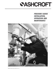
Air Density vs. <strong>Flow</strong> Factor<br />
<strong>Temp</strong>erature vs. <strong>Press</strong>ure<br />
3.50<br />
Scale Correction Factor<br />
3.00<br />
2.50<br />
2.00<br />
1.50<br />
1.00<br />
0.50<br />
<strong>Press</strong>ure in Bar<br />
10<br />
9<br />
8<br />
7<br />
6<br />
5<br />
4<br />
3<br />
2<br />
1<br />
PVC<br />
PA<br />
PVDF<br />
PSU<br />
0<br />
0.001<br />
0.002<br />
0.003<br />
0.004<br />
0.005<br />
0.006<br />
0.007<br />
0.008<br />
Air Density (g/ml)<br />
0.009<br />
0.010<br />
0.011<br />
0.012<br />
0.013<br />
0.014<br />
0<br />
-10<br />
0<br />
10<br />
20<br />
30<br />
40<br />
50<br />
60<br />
70<br />
80<br />
90<br />
<strong>Temp</strong>erature in o C<br />
100<br />
110<br />
120<br />
130<br />
55 Guardsman Road, Thornhill, Ontario, Canada, L3T 6L2<br />
Tel: 905-889-7890 request@chemline.com<br />
Fax: 905-889-8553 www.chemline.com<br />
Your Pipeline To Quality Valves, Piping, <strong>Flow</strong> <strong>Meters</strong> and Controls
LSFLO Reed Limit Switch<br />
<strong>For</strong> FC and FS <strong>Flow</strong> <strong>Meters</strong><br />
The LSFLO limit switches serve as switches for minimum<br />
and maximum or optional intermediate flow values.<br />
They are clamped to the dovetail guides (measuring<br />
tube of the FS or FC <strong>Series</strong> flow meters) and signal<br />
when the float in the measuring tube has reached or<br />
exceeded the switching position. As soon as this<br />
happens, the contact in the actual switching element<br />
(reed switch) opens or closes.<br />
The contact is closed as soon as the magnetic float<br />
moves up from below or is at the direct height of the<br />
limit switch.<br />
When exceeding the limit switch the switched<br />
condition is maintained. Only when moving down<br />
below the limit switch the switching status will be<br />
cancelled.<br />
Technical Data<br />
● Operating voltage: maximum 230 VAC<br />
● Operating current: maximum 0.5 A<br />
● Constant current when switched: maximum 1 A<br />
CONNECTIONS:<br />
● Rupturing capacity: maximum 10 W/10 VA<br />
● <strong>For</strong>ward resistance: < 150 mΩ<br />
2<br />
● Isolation resistance: > 10 10 Ω<br />
● Operating temperature: 0 o C(32 o F) to 55 o C(131 o F)<br />
● Protection: IP 65 (DIN EN 60528)<br />
● Hysteresis (switch on and off point): 3 mm<br />
● Protection: IP 65 (DIN EN 60528)<br />
2<br />
● Dimensions: 34 x 17 x 41 mm<br />
● Weight (with plug): 40 g<br />
● Connections: The polarity of the connections has<br />
no influence on the function<br />
ASV<br />
START-UP:<br />
Prior first start up it is important that the<br />
float passes the switch ZE 951 three times in<br />
order to release possible monostable<br />
behaviour due to longer off period.<br />
55 Guardsman Road, Thornhill, Ontario, Canada, L3T 6L2<br />
Tel: 905-889-7890 request@chemline.com<br />
Fax: 905-889-8553 www.chemline.com<br />
Your Pipeline To Quality Valves, Piping, <strong>Flow</strong> <strong>Meters</strong> and Controls
ZE3000 <strong>Flow</strong> Transmitter<br />
<strong>For</strong> FS <strong>Flow</strong> <strong>Meters</strong><br />
The ZE3000 flow transmitter provides a 4–20 mA output signal,<br />
generated by precise angle detection of the magnetic float.<br />
This micro-processor controlled unit is factory calibrated. This<br />
guarantees accuate flow measurement and evaluation.<br />
IMPORTANT: The flow meter to which the ZE3000 is to be fitted<br />
must be known in advance.<br />
Features<br />
● 2-Wire technology<br />
● 4–20 mA analog output (4-20.1 for 8 VDC supply; 4-22.0 for 28 VDC supply<br />
● 8–28 VDC input<br />
● Factory calibrated (flow meter to be specified when ordering)<br />
● 11 point calibration<br />
DIMENSIONS:<br />
2.95"<br />
1.42"<br />
● Non-volatile value storage<br />
0.59"<br />
● 0 Button to compensate for the surrounding magnetic influences<br />
● Factory setting of the lower limit value (low-cut-off) 0-99%<br />
according to customer’s specificaitons<br />
● Factory time lag (low-pass filter) 0.1-2.5 sec. according to<br />
customer’s specifications<br />
● Measuring accuracy: < 0.5%<br />
● <strong>Temp</strong>erature range: –30 o C(–20 o F) to 65 o C(150 o F)<br />
6.93"<br />
2.76"<br />
INSTALLATION:<br />
Screw clamps are used to fit the ZE3000 on the dovetail guide<br />
of the flow meter.<br />
During installation, ensure that the notch of the ZE3000<br />
coincides with the 50% mark on the flow meter scale.<br />
Following this, proceed with the wiring according to the<br />
diagram.<br />
WIRING:<br />
Pin 1: 8-28 VDC<br />
1.69"<br />
START-UP:<br />
After installation and wiring, press the 0 button<br />
for at least 2 sec. to compensate for<br />
surrounding magnetic influences. During this<br />
phase ensure that the float is in its bottom<br />
position, ie. no flow must take place.<br />
Pin 2: GND<br />
Concealed<br />
0 button<br />
55 Guardsman Road, Thornhill, Ontario, Canada, L3T 6L2<br />
Tel: 905-889-7890 request@chemline.com<br />
Fax: 905-889-8553 www.chemline.com<br />
Your Pipeline To Quality Valves, Piping, <strong>Flow</strong> <strong>Meters</strong> and Controls<br />
Note:<br />
Do not press button during normal operation.
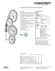
ZE3075 <strong>Flow</strong> Transmitter<br />
<strong>For</strong> FC <strong>Flow</strong> <strong>Meters</strong><br />
The ZE3075 flow transmitter provides a 2- wire 4–20 mA output<br />
signal, generated by precise height detection of the magnetic<br />
float.<br />
This micro-processor controlled unit is field calibrated. This<br />
guarantees accuate flow measurement and evaluation.<br />
The magnetic float travels along the reed chain of switches<br />
activating them.<br />
Features<br />
● 2-Wire technology<br />
● 4–20 mA analog output (4-20.1 for 8 VDC supply; 4-22.0 for 28 VDC supply<br />
● 18–30 VDC input<br />
● Field calibration<br />
● Non-volatile value storage<br />
● Measuring length: 114 mm (4.5")<br />
● Measuring resolution: 3.5 mm (0.138")<br />
● Measuring accuracy: 3%<br />
● <strong>Temp</strong>erature range: –20 o C(–4 o F) to 70 o C(158 o F)<br />
INSTALLATION:<br />
Screw clamps are used to fit the ZE3075 on the dovetail guide<br />
of the flow meter.<br />
During installation, ensure that the top and bottom notches<br />
of the ZE3075 coincide with the 10% and 100% marks on the<br />
flow meter scale.<br />
Following this, proceed with the wiring according to the<br />
diagram.<br />
WIRING:<br />
The unit is connected with a commercially available<br />
unshielded cable.<br />
Where electro-magnetic interference is to be expected, we<br />
recommend the use of a shielded cable.<br />
Cable cross section: max. 0.75 mm 2 cable outer diameter:<br />
6 ... 8 mm.<br />
Flange Connector:<br />
Circuit Diagram:<br />
3<br />
2<br />
4<br />
1<br />
1. Signal (+)<br />
2. Signal (+)<br />
3. n.c.<br />
4. n.c.<br />
U<br />
I<br />
(-)<br />
(+)<br />
2<br />
1<br />
COMPONENTS:<br />
1. Notches for the<br />
measuring range<br />
2. Potentiometer for the<br />
upper limit value of<br />
the output signal<br />
3. Potentiometer for the<br />
lower limit value of<br />
the output signal<br />
4. Plug connector<br />
55 Guardsman Road, Thornhill, Ontario, Canada, L3T 6L2<br />
Tel: 905-889-7890 request@chemline.com<br />
Fax: 905-889-8553 www.chemline.com<br />
Your Pipeline To Quality Valves, Piping, <strong>Flow</strong> <strong>Meters</strong> and Controls<br />
CALIBRATION:<br />
Compensation between the non-linear scaling<br />
of the flowmeter and the linear output signal of<br />
the flow data sensor must be performed by<br />
adjusting, preferably between 20% and 80% of<br />
the flow rate.<br />
20% corresponds to 7.2mA and 80% to 16.8mA.<br />
● Connect the ampermeter and the respective<br />
voltage supply to the flow data sensor<br />
● Allow 20% of the flow to pass the FC flow<br />
meter<br />
● Set the min. trimmer potentiometer (3) such<br />
that the corresponding current (7.2mA) is<br />
shown in the ampermeter<br />
● Allow 80% of the flow to pass the FC flow<br />
meter<br />
● Set the max. trimmer potentiometer (3) such<br />
that thecorresponding current (16.8mA) is<br />
shown in the ampermeter<br />
● Check the values at 20% and 80% several<br />
times and repeat the adjustment, if required