MK 45A Stainless Steel Design
MK 45A Stainless Steel Design
MK 45A Stainless Steel Design

You also want an ePaper? Increase the reach of your titles
YUMPU automatically turns print PDFs into web optimized ePapers that Google loves.
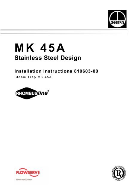
M K 4 5 A<br />
<strong>Stainless</strong> <strong>Steel</strong> <strong>Design</strong><br />
Installation Instructions 810603-00<br />
S t e a m T r a p M K 4 5 A
Capacity Chart<br />
Max. flowrate of cold condensate<br />
for <strong>MK</strong> <strong>45A</strong>-1.<br />
Max. flowrate of hot condensate<br />
for <strong>MK</strong> 45 A-2.
Part Drawings
Checking of Capsule<br />
Capsule for nozzle insert with tandem seat : 5 N 1, 5 U 1<br />
E1 F1<br />
Capsule E2for nozzle insert with tandem seat F2 : 5 N 2, 5 U 2<br />
4
Key<br />
Hexagon-head screw M 10x25 to EN 24017, made of 24 CrMo 5 (1.7258)<br />
Name plate<br />
Cover<br />
Spring<br />
Capsule<br />
E1 Capsule for tandem seat<br />
E2 Capsule for single seat<br />
Nozzle insert with non-return valve action<br />
Nozzle insert with tandem seat<br />
Nozzle insert with single seat<br />
Bush (interference-fitted and cannot be replaced)<br />
Gasket 40x48x2<br />
Body<br />
Strainer<br />
Plug gasket A24x29<br />
Plug<br />
Code number of pressure rating<br />
5= p 22 bar<br />
10<br />
N Code letter of opening temperature<br />
N = Standard, t approx. 10 K<br />
U = Undercooling, t approx. 30 K<br />
Code number of capacity<br />
1 = Low capacity<br />
2 = High capacity<br />
Manufacturing code number<br />
5
Contents<br />
Important Notes<br />
6<br />
Page<br />
Safety Note .....................................................................................................................7<br />
Danger ........................................................................................................................... 7<br />
Explanatory Notes<br />
Scope of supply .............................................................................................................. 8<br />
Description .....................................................................................................................8<br />
Function .......................................................................................................................... 8<br />
Technical data ................................................................................................................ 9<br />
Name plate .....................................................................................................................9<br />
Installation<br />
<strong>MK</strong><strong>45A</strong> ......................................................................................................................... 10<br />
Flanged traps ............................................................................................................... 10<br />
Screwed-socket traps ................................................................................................... 10<br />
Socket-weld traps ......................................................................................................... 10<br />
Heat treatment of welds ............................................................................................... 11<br />
Maintenance<br />
Check steam trap ......................................................................................................... 12<br />
Check capsule .............................................................................................................. 4<br />
Clean/exchange capsule and nozzle insert .................................................................. 12<br />
Clean/exchange strainer .............................................................................................. 12<br />
Torques ........................................................................................................................ 13<br />
Spare Parts<br />
Spare parts list ..............................................................................................................13
Important Notes<br />
Safety Note<br />
Use steam trap <strong>MK</strong> 45 A only for the discharge of condensate from steam lines.<br />
Installation must only be performed by qualified staff.<br />
Qualified staff are those persons who – through adequate training in engineering, the use<br />
and application of equipment in accordance with regulations concerning steam systems,<br />
and first aid & accident prevention – have achieved a recognised level of competence<br />
appropriate to the installation and commissioning of this device.<br />
Danger<br />
The steam trap is under pressure during operation.<br />
When loosening flanged connections or plugs, hot water and/or steam may<br />
escape. This presents the risk of severe burns to the whole body. Installation<br />
and maintenance work should only be carried out when the system is<br />
depressurized: isolate the trap from both upstream and downstream<br />
pressure.<br />
The trap becomes hot during operation.<br />
This presents the danger of severe burns to hands and arms. Installation and<br />
maintenance work should only be carried out when the system is cold.<br />
Sharp edges on internal parts present a danger of cuts to hands. Always<br />
wear industrial gloves for installation and maintenance work.<br />
7
Explanatory Notes<br />
Scope of Supply<br />
<strong>MK</strong>45 A<br />
Description<br />
8<br />
1 Steam trap <strong>MK</strong><strong>45A</strong> 1 Installation manual<br />
Thermostatic steam trap with corrosion-resistant thermostatic capsule unaffected by<br />
waterhammer. Integral Y-type strainer and non-return valve. Asbestos-free cover gasket<br />
(graphite/CrNi). Installation in any position.<br />
The traps with standard capsule “N” discharge condensate with virtually no banking-up, the<br />
traps with special capsule “U” with an undercooling of approx. 30 K (degC).<br />
n <strong>MK</strong> 45 A-1 with tandem seat (double sealing)<br />
Particularly suitable for low condensate flowrates. Optionally either with<br />
standard capsule “5 N 1” or undercooling capsule “5 U 1”.<br />
n <strong>MK</strong> 45 A-2 with single seat<br />
For larger condensate flowrates.<br />
Optionally either with standard capsule “5 N 2” or undercooling capsule “5 U<br />
2”.<br />
Function<br />
The <strong>MK</strong> 45 A is a steam trap with membrane regulator. The capsule of the regulator is<br />
filled with a liquid having an evaporation temperature which is just a few degrees below<br />
that of water. When cold condensate flows through the steam trap, the liquid filling is<br />
completely condensed due to the low ambient temperature. The pressure inside the<br />
capsule is lower than the surrounding pressure (service pressure), which means that the<br />
membrane contracts, pushing the valve disc in the opening position. As the condensate<br />
temperature rises, the liquid filling starts to evaporate. The pressure in the capsule<br />
rises, the membrane expands, moving the valve disc in the closed position.<br />
Automatic air-venting is provided both, during start-up and during normal operation. The<br />
correct functioning of the <strong>MK</strong> 45 A is unaffected by fluctuations in the inlet pressure or<br />
by back pressure.The <strong>MK</strong> 45 A can also be used as steam vent.
Technical Data<br />
Pressure /Temperature Ratings<br />
Max. service pressure [barg]<br />
[psig]<br />
Related temperature [°C]<br />
[°F]<br />
Max. differential pressure<br />
(Inlet pressure minus<br />
outlet pressure)<br />
Materials<br />
Body<br />
Cover<br />
040<br />
580<br />
020<br />
068<br />
029<br />
421<br />
300<br />
572<br />
22 barg (320 psig)<br />
024<br />
348<br />
400<br />
752<br />
DIN reference ASTM equivalent*<br />
O l d d e s i g n a t i o n N e w d e s i g n a t i o n<br />
X2CrNiMo 17132<br />
(1.4404)<br />
X2CrNiMo 17132<br />
(1.4404)<br />
A 182 F 316 L<br />
A 182 F 316 L<br />
Screws A2-70 A 193 B 8<br />
Body<br />
Graphite<br />
gasket<br />
Thermostatic<br />
Hastelloy<br />
capsule<br />
® / <strong>Stainless</strong> steel<br />
Other<br />
<strong>Stainless</strong> steel<br />
internals<br />
* Physical and chemical properties comply with DIN grade. ASTM nearest equivalent grade is<br />
stated for guidance only.<br />
Name Plate<br />
Capacity rating 1 Capacity rating 2<br />
Low flowrate High flowrate<br />
Thermostatic<br />
capsule<br />
U<br />
5N 1 1<br />
5U<br />
Reference point for Reference point for<br />
ultrasonic functional test ultrasonic functional test<br />
Fig. 4 Fig. 5<br />
Thermostatic<br />
capsule<br />
U<br />
5N2 2<br />
5U<br />
9
Installation<br />
<strong>MK</strong>45 A<br />
The steam trap <strong>MK</strong> <strong>45A</strong> can be installed in any position. In the case of a horizontal<br />
installation, make sure that the cover is at the top.<br />
Flanged Traps<br />
1. Take care of correct position of installation.<br />
2. Take care of flow direction. The flow arrow is on the trap body.<br />
3. Consider space required for opening trap. When the trap is installed a minimum<br />
space of 30 mm is required for removing cover . C<br />
4. Remove plastic plugs. They are only used as transit protection.<br />
5. Clean seating surfaces of both flanges.<br />
6. Install steam trap.<br />
Screwed-Socket Traps<br />
1. Take care of correct position of installation.<br />
2. Take care of flow direction. The flow arrow is on the trap body.<br />
3. Consider space required for opening trap. When the trap is installed a minimum<br />
space of 30 mm is required for removing the cover . C<br />
4. Remove plastic plugs. They are only used as transit protection.<br />
5. Clean threads of screwed sockets.<br />
6. Install steam trap.<br />
Socket-Weld Traps<br />
1. Take care of correct position of installation.<br />
2. Take care of flow direction. The flow arrow is on the trap body.<br />
3. Consider space required for opening trap. When the trap is installed a minimum<br />
space of 30 mm is required for removing the cover . C<br />
4. Remove plastic plugs. They are only used as transit protection.<br />
5. Clean thermostatic capsule as described under Maintenance.<br />
6. Clean socket-weld ends.<br />
7. Arc-weld trap only manually (welding process 111 and 141 in accordance with<br />
DIN EN 24063).<br />
10
Installation – con tin u ed –<br />
Attention<br />
n Only qualified welders certified e. g. according to DIN EN 287 may weld<br />
the steam trap into pressurized lines.<br />
n Do not insulate steam trap.<br />
Heat treatment of welds<br />
A subsequent heat treatment of the welds is not required.<br />
11
Maintenance<br />
GESTRA steam traps type <strong>MK</strong> 45 A do not require any special maintenance. However, if<br />
used in new installations which have not been rinsed it may be necessary to check and<br />
clean the trap.<br />
Check steam trap<br />
You can check the steam trap <strong>MK</strong> 45 A for steam loss during operation using the<br />
ultrasonic measuring unit VAPOPHONE ® or the test unit TRAPt est ® .<br />
The reference points are at the name plate on the cover, Fig. 4, Fig. 5.<br />
Should you detect any loss of live steam clean the trap and/or replace the control unit.<br />
Clean/exchange capsule and nozzle insert<br />
1. Take heed of the note “Danger” on page 7.<br />
2. Undo body screws . Remove cover from the body .<br />
A C I<br />
3. Remove and clean capsule . Unscrew nozzle insert .<br />
E F<br />
4. Replace capsule E in case of visible signs of wear or damage.<br />
5. Clean body, internals and all gasket surfaces.<br />
6. Apply heat-resistant lubricant to all threads and the seating surface of the nozzle<br />
insert and the cover (use for instance WINIX ® 2150).<br />
7. Screw in nozzle insert and tighten with a torque of 90 Nm.<br />
8. Position capsule onto the nozzle insert and press evenly, such that the<br />
E F<br />
capsule snaps into place.<br />
9. Replace gasket only if there are visual signs of damage. Use the same<br />
H<br />
cover . Always replace gasket when using a new cover or the cover of<br />
C H C<br />
another steam trap.<br />
10. Put cover onto the body. Tighten hexagon-head screws alternately and in several<br />
A<br />
steps to a torque of 25 Nm.<br />
Tools<br />
n Spanner A. F. 16 mm to DIN 3113, form B<br />
n Spanner A. F. 22 mm to DIN 3113, form B<br />
n Torque spanner 20 – 120 Nm to DIN ISO 6789<br />
Clean/exchange strainer<br />
Take heed of note “Danger” on page 7.<br />
1.<br />
2.<br />
3.<br />
4.<br />
5.<br />
6.<br />
7.<br />
12<br />
Unscrew sealing plug and remove strainer .<br />
L J<br />
Clean strainer, sealing plug and gasket seats.<br />
Exchange strainer and sealing plug in case of visible signs of wear or damage.<br />
Exchange gasket if damaged.<br />
K<br />
Apply heat-resistant lubricant to the thread of the sealing plug (use for instance<br />
WINIX ® 2150).<br />
Replace gasket and strainer and tighten sealing plug with a torque of<br />
K J L<br />
120 Nm.<br />
Tools<br />
n Spanner A. F. 30 mm to DIN 3113, form B<br />
n Torque spanner 20 – 120 Nm to DIN ISO 6789<br />
WINIX ® 2150 is a registered trademark of WINIX GmbH, Norderstedt
Maintenance – con tin u ed –<br />
Torques<br />
Item<br />
<strong>Design</strong>ation<br />
Torque [Nm]<br />
F Nozzle insert 90<br />
A Body screws 25<br />
L<br />
Sealing plug<br />
All torques are based on 20 °C room temperature.<br />
Spare Parts<br />
Spare Parts List<br />
Item <strong>Design</strong>ation<br />
E1 F1 H<br />
E2 F2 H<br />
K J L<br />
E1<br />
E2<br />
H<br />
K<br />
Membrane regulator,<br />
complete 5 N 1<br />
Membrane regulator,<br />
complete 5U 1<br />
Membrane regulator,<br />
complete 5 N 2<br />
Membrane regulator,<br />
complete 5U2<br />
Strainer set, complete<br />
Ref. no.<br />
120<br />
<strong>MK</strong> <strong>45A</strong>-1 <strong>MK</strong> <strong>45A</strong>-2<br />
375109<br />
375111<br />
Thermostatic capsule 5N 1 376165 1 )<br />
Thermostatic capsule 5U 1<br />
Thermostatic capsule 5N2<br />
375110<br />
375112<br />
375382 375382<br />
376166 1 )<br />
376167 1 )<br />
Thermostatic capsule 5U2 376168 1 )<br />
Cover gasket 2 ) 40x48x2,<br />
graphite<br />
375159 375159<br />
Plug gasket 2 ) A24x29,<br />
stainless steel<br />
375162 375162<br />
1) Packaged 10 per box. Contact your local dealer for smaller quantities.<br />
2) Minimum purchasing quantity 50 pcs. Contact your local dealer for smaller quantities.<br />
TRA GmbH · Bremen · Printed in Germany<br />
13