Product Information - VEGASWING for liquids
Product Information - VEGASWING for liquids
Product Information - VEGASWING for liquids

Create successful ePaper yourself
Turn your PDF publications into a flip-book with our unique Google optimized e-Paper software.
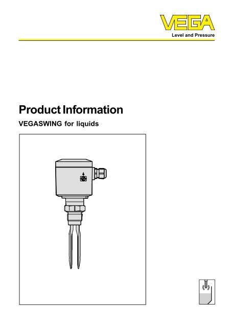
<strong>Product</strong> <strong>In<strong>for</strong>mation</strong><br />
<strong>VEGASWING</strong> <strong>for</strong> <strong>liquids</strong><br />
Level and Pressure
Contents<br />
1 <strong>Product</strong> description<br />
Contents<br />
1.1 General .................................................................................................................. 3<br />
1.3 <strong>VEGASWING</strong> series 80A ...................................................................................... 3<br />
1.2 <strong>VEGASWING</strong> series 70A ...................................................................................... 3<br />
1.4 Recurring test acc. to WHG ................................................................................. 4<br />
2 Function and application<br />
2.1 Principle of operation ............................................................................................ 5<br />
2.2 Measuring system ................................................................................................ 5<br />
3 Types and versions<br />
3.1 <strong>VEGASWING</strong> vibrating level switches - Overview ............................................. 6<br />
3.2 Technical data and dimensions ............................................................................ 8<br />
3.3 Technical data signal conditioning instruments and dimensions ..................... 21<br />
3.4 Flanges ................................................................................................................ 25<br />
3.5 Application examples ......................................................................................... 27<br />
3.6 Approvals ............................................................................................................ 28<br />
4 Electrical connection<br />
4.1 <strong>VEGASWING</strong> 71A/75A ....................................................................................... 29<br />
4.2 <strong>VEGASWING</strong> 80A ............................................................................................... 30<br />
4.3 Signal conditioning instruments series 500 and series 600 ............................. 32<br />
2 <strong>VEGASWING</strong>
1 <strong>Product</strong> description<br />
1.1 General<br />
<strong>VEGASWING</strong> vibrating level switches<br />
detect levels of <strong>liquids</strong>.<br />
The tuning <strong>for</strong>k of <strong>VEGASWING</strong> detects<br />
liquid levels. Typical applications<br />
are overfill protection and dry<br />
run protection of pumps. Vibrating<br />
level switches are available as compact<br />
instruments, i.e. with integrated<br />
processing or <strong>for</strong> connection to a signal<br />
conditioning instrument.<br />
<strong>VEGASWING</strong> vibrating level switches<br />
detect liquid levels with a viscosity of<br />
0.2 … 10.000 mPa s and a density of<br />
≥ 0.5 g/cm 3 . Modular construction<br />
enables their use in vessels, tanks<br />
and pipelines. Typical applications<br />
are overfill and dry run protections.<br />
Due to the simple and rugged measuring<br />
system, <strong>VEGASWING</strong> is virtually<br />
unaffected by the chemical and<br />
physical features of the liquid. It works<br />
even under unfavourable conditions<br />
such as turbulences, air bubbles,<br />
foam generation, buildup or varying<br />
products.<br />
integrated fault monitoring<br />
fixed, exactly reproducible switching<br />
point<br />
switching condition visible with<br />
closed instrument (LED)<br />
insensitive to buildup due to large<br />
gaps<br />
insensitive to external vibrations<br />
setup without adjustment<br />
compact<br />
individual installation position<br />
selectable min. or max. mode<br />
Operating pressure up to 40 bar<br />
<strong>Product</strong> description<br />
1.2 <strong>VEGASWING</strong> series 70A<br />
<strong>VEGASWING</strong> 71A/75A vibrating level<br />
switches are especially suitable <strong>for</strong><br />
tight installation conditions.<br />
<strong>VEGASWING</strong> 75A is mainly suitable<br />
<strong>for</strong> level detection in the food<br />
processing and pharmaceutical industry.<br />
Due to the polished sensor<br />
surface (Ra < 0.5 µm or RA < 1.5 µm)<br />
bacteria have no chance to collect.<br />
<strong>VEGASWING</strong> 75A is also suitable <strong>for</strong><br />
CIP and SIP cleaning.<br />
Many different hygienic fittings such<br />
as conus with compression nut, Tri-<br />
Clamp 1 1 / 2 " and 2", bolting, Tuchenhagen<br />
Varivent or special hygienic<br />
connections are available.<br />
transistor output PNP/NPN selectable<br />
on oscillator<br />
permanently shortcircuit proof and<br />
overload resistant<br />
operating temperature from -40°C<br />
to +150°C<br />
stainless steel housing protection<br />
IP 67<br />
simple electrical connection by plug<br />
connector<br />
<strong>VEGASWING</strong> 71<br />
1.3 <strong>VEGASWING</strong> series 80A<br />
• Four different oscillators, relay output,<br />
contactless electronic switch,<br />
transistor output, two-wire output<br />
All standard mechanical connections<br />
possible, e.g. thread, flange,<br />
hygienic fittings etc.<br />
High resistance also available in<br />
aggressive products by using suitable<br />
materials such as e.g. enamel<br />
Protection IP 66<br />
Approvals acc. to PTB Zone 0 EEx ia<br />
IIC T6, CENELEC EEx ia IIC T6, WHG<br />
Suitable <strong>for</strong> foodstuffs<br />
For use in very aggressive products,<br />
<strong>VEGASWING</strong> 81 A can be coated with<br />
ECTFE (Halar), Hastelloy or enamel<br />
or <strong>VEGASWING</strong> 83A can be coated<br />
with enamel and Halar up to 3000 mm<br />
or Säkaphen and Hastelloy C4.<br />
For product temperatures up to<br />
150°C <strong>VEGASWING</strong> 80A can be<br />
equipped with a temperature adapter.<br />
<strong>VEGASWING</strong> 81<br />
<strong>VEGASWING</strong> 3
1.4 Recurring test acc. to<br />
WHG<br />
According to the type approval acc.<br />
to WHG (Z-65.11-154) the recurring<br />
test acc. to WHG can be carried out<br />
by pushing the test key on the VEGA-<br />
TOR 536 Ex, 537 EX, 636 Ex signal<br />
conditioning instrument. The sensor<br />
must neither be removed nor response<br />
triggered by filling the vessel.<br />
This is valid <strong>for</strong> <strong>VEGASWING</strong> 81A EX<br />
and 83A EX with two-wire oscillator<br />
SWING E82B EX.<br />
In mode A (overfill protection) VEGAS-<br />
WING 81A EX and 83A EX meet the<br />
fail safe requirements acc. to class 3<br />
(AK 1 … 3) according to DIN 19 251.<br />
<strong>Product</strong> description<br />
4 <strong>VEGASWING</strong>
2 Function and application<br />
2.1 Principle of operation<br />
<strong>VEGASWING</strong> vibrating level switches<br />
detect levels of virtually all <strong>liquids</strong>.<br />
Measuring principle VEGAS-<br />
WING<br />
The tuning <strong>for</strong>k is piezoelectrically<br />
energised and vibrates at its mechanical<br />
resonance frequency of<br />
approx. 400 Hz. When the tuning <strong>for</strong>k<br />
is submerged in the product, the frequency<br />
changes. This change is detected<br />
by the integrated oscillator and<br />
converted into a switching command.<br />
The integrated fault monitoring detects:<br />
- interruption of the connection cable<br />
to the piezo elements<br />
- extreme abrasion on the tuning <strong>for</strong>k<br />
- break of the tuning <strong>for</strong>k<br />
- no vibration.<br />
If one of the stated failures is determined<br />
or in case of voltage loss, the<br />
electronics takes a defined switching<br />
condition, i.e. depending on the electronics<br />
version<br />
- the contactless electronic switch<br />
opens<br />
- the relay deenergises<br />
- the output transistor blocks.<br />
With the two-wire output version the<br />
failure is signalled via a defined current<br />
to the connected VEGATOR signal<br />
conditioning instrument.<br />
Function and application<br />
Compact instruments<br />
All vibrating level switches are available<br />
as compact instruments, i.e. all<br />
instruments can be operated without<br />
external processing. The integrated<br />
electronics processes the level signal<br />
and makes an output signal (corresponding<br />
to the installed oscillator)<br />
available. With this output signal, a<br />
connected instrument can be directly<br />
operated (e.g. a warning system, a<br />
PLC, a pump etc.).<br />
The installation of one of the following<br />
oscillators makes a compact instrument<br />
out of the vibrating level switch:<br />
- contactless electronic switch (C)<br />
- relay output (R)<br />
- transistor output (T).<br />
Vibrating level switch with<br />
signal conditioning instrument<br />
Oscillator B (two-wire output) can be<br />
mounted in <strong>VEGASWING</strong> series 80A.<br />
The vibrating level switches can be<br />
then connected to a signal conditioning<br />
instrument. Depending on the<br />
requirements, there is a choice of the<br />
following signal conditioning instruments:<br />
- VEGATOR 536 Ex<br />
- VEGATOR 537 Ex<br />
- VEGATOR 636 Ex<br />
2.2 Measuring system<br />
A measuring system with a vibrating<br />
level switch can be realized in two<br />
ways.<br />
Level detection of <strong>liquids</strong> with<br />
compact instrument<br />
Measuring system with <strong>VEGASWING</strong> as compact<br />
instrument<br />
A measuring system consists of:<br />
- a <strong>VEGASWING</strong> vibrating level switch<br />
with integrated oscillator<br />
- connected instruments operated<br />
with <strong>VEGASWING</strong>.<br />
Level detection of <strong>liquids</strong> with<br />
signal conditioning instrument<br />
Measuring system with <strong>VEGASWING</strong> with separate<br />
processing<br />
A measuring system consists of:<br />
- a <strong>VEGASWING</strong> vibrating level switch<br />
with integrated oscillator<br />
- a VEGATOR level switch or the VE-<br />
GALOG processing system<br />
<strong>VEGASWING</strong> 5<br />
!
3 Types and versions<br />
3.1 <strong>VEGASWING</strong> vibrating level switches - Overview<br />
Version<br />
Standard (fixed installation length)<br />
Tube version<br />
Approvals<br />
Ex-Zone 0 acc. to ATEX 100 a EEx ia IIC T6<br />
Ex-Zone 0 acc. to ATEX 100 a EEx d IIC T6<br />
Overfill protection acc. to WHG<br />
Mechanical connection<br />
G 1 A<br />
1" NPT<br />
Flange from DN 32, ANSI 2"<br />
Tri-Clamp 1.5"<br />
Tri-Clamp 2"<br />
Conus DN 25<br />
Bolting DN 40<br />
Bolting DN 50<br />
Hygienic connection with compression nut<br />
F40 PN 25<br />
Hygienic connection with tension flange<br />
DN 32 PN 25<br />
Varivent<br />
Tuning <strong>for</strong>k material<br />
1.4581 (316)<br />
2.4610 (Hastelloy C4)<br />
Material, mechanical connection<br />
1.4571 (316 Ti)<br />
2.4610 (Hastelloy C4)<br />
Coating<br />
ECTFE (Halar)<br />
Säkaphen<br />
Enamel<br />
Types and versions<br />
71A 71A 75A 75A 81A 81A 83A 83A 81A 81A 83A<br />
83A<br />
ExD ExD ExD ExD<br />
ExD<br />
6 <strong>VEGASWING</strong>
Oscillator<br />
Contactless electronic switch (C)<br />
Relay output (R) DPDT<br />
Transistor output (T)<br />
Two-wire output 8 mA/16 mA (B)<br />
Temperature adapter<br />
1.4571 (316 Ti)<br />
Others<br />
Locking G 1 1 / 2 A (unpressurized)<br />
Locking G 1 1 / 2 A up to 25 bar<br />
Types and versions<br />
71A 71A 75A 75A 81A 81A 83A 83A 81A 81A 83A<br />
83A<br />
ExD ExD ExD ExD<br />
ExD<br />
<strong>VEGASWING</strong> 7
3.2 Technical data and dimensions<br />
<strong>VEGASWING</strong> 71A/75A<br />
Housing<br />
Housing material stainless steel 1.4571<br />
Protection IP 67<br />
Plug connection 4-pole plug<br />
with status indication (illuminated ring)<br />
Terminals max. 1 x 1.5 mm 2<br />
Process connection<br />
<strong>VEGASWING</strong> 71A<br />
- thread G 1 A or 1" NPT<br />
- material 1.4571 (stainless steel)<br />
<strong>VEGASWING</strong> 75A<br />
- thread G 1 A or 1" NPT<br />
- conus DN 25<br />
- Tri-Clamp 1 1 / 2 " or 2"<br />
- bolting DN 40 or DN 50<br />
- Tuchenhagen Varivent<br />
- hygienic connection with compression nut F 40 PN 25<br />
- hygienic connection with tension flange DN 32 PN 25<br />
Tuning <strong>for</strong>k<br />
Material 1.4581 (stainless steel)<br />
Weight<br />
Total weight 0.4 kg (<strong>VEGASWING</strong> 71A)<br />
Ambient conditions<br />
Ambient temperature on the housing -40°C ... +70°C<br />
Storage and transport temperature -40°C … +80°C<br />
<strong>Product</strong> temperature -40°C ... +150°C<br />
Operating pressure<br />
Types and versions<br />
Permissible ambient temperature<br />
8 <strong>VEGASWING</strong><br />
70˚C<br />
50˚C<br />
30˚C<br />
80˚<br />
90˚<br />
100˚<br />
Operating pressure max. 25 bar<br />
Test pressure max. 40 bar<br />
<strong>Product</strong><br />
Viscosity 0.2 ... 10.000 mPa s<br />
Density ≥ 0.6 g/cm 3<br />
Electronics (transistor output SWING E72T)<br />
110˚ 120˚ 130˚ 140˚ 150˚C<br />
<strong>Product</strong><br />
temperature<br />
with temperature<br />
adapter<br />
Supply voltage 10 ... 55 V DC<br />
Power consumption max. 0.5 W<br />
Output floating transistor output NPN/PNP selectable<br />
Load current max. 400 mA<br />
(output - overload and permanently shortcircuit<br />
resistant)<br />
Voltage loss max. 1 V<br />
Turn-on voltage max. 55 V DC<br />
Blocking current < 10 µA<br />
Protection class II<br />
Overvoltage category III
Electronics (contactless electronic switch SWING E72C)<br />
Supply voltage 20 … 250 V AC, 50/60 Hz or 20 … 250 V DC<br />
Output contactless electronic switch<br />
Internal current requirement approx. 3 mA (via load circuit)<br />
Load current min. 10 mA<br />
max. 400 mA<br />
(at I > 300 mA the ambient temperature can be<br />
max. 60°C) max. 4 A up to 40 ms<br />
Protection class I<br />
Overvoltage category III<br />
Modes A/B mode by electrical connection in the<br />
connection plug<br />
A - max. detection, overfill protection<br />
B - min. detection, dry run protection of pumps<br />
Function<br />
Modes A/B mode by polarisation of the supply voltage<br />
A - max. detection or overfill protection<br />
B - min. detection or dry run protection of pumps<br />
Integration time approx. 0.5 sec<br />
Meas. frequency approx. 400 Hz<br />
Hysteresis approx. 4 mm with perpendicular installation<br />
Signal lamp illuminated ring with two-colour LED (green - output<br />
conducts, red - output blocks) <strong>for</strong> indication of the<br />
switching condition (only in conjunction with plug<br />
connection)<br />
CE con<strong>for</strong>mity<br />
<strong>VEGASWING</strong> 81A and 83A Housing<br />
Types and versions<br />
<strong>VEGASWING</strong> 71A and 75A vibrating level switches meet the protective regulations of EMC (89/336/<br />
EWG) and NSR (73/23/EWG). Con<strong>for</strong>mity has been judged by means of a typical configuration by<br />
means of the following standards:<br />
EMC Emission EN 50 081 - 1: 1992<br />
Susceptibility EN 50 082 - 2: 1995<br />
NSR EN 61 010 - 1: 1993<br />
Housing material PBT (Polyester)<br />
Protection IP 66<br />
Cable entry 1 x M20 x 1.5 (E82 R: 2 x M20 x 1.5)<br />
Terminals max. 1 x 1.5 mm 2<br />
Mechanical connection<br />
Thread G 1 A or 1" NPT<br />
- material 1.4571 (stainless steel) or Hastelloy C4 (2.4610)<br />
Flanges DIN and ANSI from DN 50<br />
see table "3.5 Flanges"<br />
- material 1.4571, 1.4571 with Hastelloy C4 plating<br />
DN 50 PN 40 enamelled steel<br />
Hygienic fittings<br />
- material 1.4571<br />
- conus DN 25<br />
- bolting DN 40, DN 50<br />
- Tri-Clamp 1 1 / 2 ", 2"<br />
Tuning <strong>for</strong>k<br />
Material 1.4581 (stainless steel), Hastelloy C4, Hastelloy C4<br />
enamelled, 1.4581 with Säkaphen or ECTFE coated<br />
Extension tube (<strong>VEGASWING</strong> 83A)<br />
Material 1.4571 (stainless steel), Hastelloy C4, Hastelloy C4<br />
enamelled, 1.4571 with Säkaphen or ECTFE coated<br />
Length<br />
- steel 1.4571, Hastelloy C4 200 mm … 4 m<br />
- Hastelloy C4 enamelled 200 mm… 1200 mm<br />
<strong>VEGASWING</strong> 9
Weight<br />
Plastic housing approx. 1.5 kg<br />
Stainless steel housing approx. 2.0 kg<br />
Tube extension (<strong>VEGASWING</strong> 83) approx. 0.11 kg/m<br />
Ambient conditions<br />
Ambient temperature on the housing -40°C … +70°C<br />
Storage and transport temperature -40°C … +70°C<br />
<strong>Product</strong> temperature -40°C … +100°C<br />
briefly (30 mins.) up to 150°C<br />
(only <strong>for</strong> instruments without approval)<br />
<strong>Product</strong> temperature with<br />
temperature adapter of 1.4571 (option) -40°C … +150°C<br />
Operating pressure<br />
Types and versions<br />
Permissible ambient temperature<br />
10 <strong>VEGASWING</strong><br />
70˚C<br />
60˚C<br />
50˚C<br />
Operating pressure max. 25 bar<br />
Test pressure max. 40 bar<br />
<strong>Product</strong><br />
100˚ 110˚ 120˚ 130˚ 140˚ 150˚C<br />
Viscosity<br />
- dynamic 0.2 … 10.000 mPa s (with density 1)<br />
Density 0.7 … 2.5 g/cm 3<br />
(0.5 … 0.7 g/cm 3 by readjusting)<br />
Function<br />
<strong>Product</strong><br />
temperature<br />
with temperature<br />
adapter<br />
Modes A/B mode in oscillator or definition via the signal<br />
conditioning instrument (SWING E82B)<br />
A - max. detection or overfill protection<br />
B - min. detection or dry run protection<br />
Integration time approx. 500 ms<br />
Meas. frequency approx. 380 Hz<br />
Hysteresis approx. 4 mm with perpendicular installation<br />
Signal lamp<br />
- SWING E80C, R, T LED <strong>for</strong> indication of the switching condition<br />
- SWING E80 Z, E80 Z Ex LED lights when tuning <strong>for</strong>k is covered<br />
Locking up to 25 bar or unpressurised<br />
Tube diameter of the sensor ∅ 29 mm (DIN 2463/2462 D4-T3)<br />
Material 1.4571 or 1.4435<br />
<strong>Product</strong> temperature -50°C … +150°C<br />
Operating pressure<br />
- ARV unpressurised<br />
- ARV2…B 25 bar<br />
CE con<strong>for</strong>mity<br />
<strong>VEGASWING</strong> 81A and 83A vibrating level switches meet the protective regulations of EMC (89/336/<br />
EWG) and NSR (73/23/EWG). Con<strong>for</strong>mity has been judged acc. to the following standards:<br />
EMC Emission EN 50 081 - 1: 1992<br />
Susceptibility EN 50 082 - 2: 1995<br />
NSR EN 61 010 - 1: 1993
<strong>VEGASWING</strong> 81A EXD and<br />
83A EXD<br />
1) Note the in<strong>for</strong>mation in the con<strong>for</strong>mity certificate<br />
or the EC type approval.<br />
Types and versions<br />
Housing<br />
Housing material Aluminium (plastic coated)<br />
Protection IP 66 and IP 67 (meets both protections)<br />
Cable entry<br />
Terminals<br />
1<br />
/2 “ NPT EExd<br />
max. 1 x 1.5 mm2 wire cross-section<br />
Mechanical connection<br />
Thread G 1 A or 1“ NPT<br />
- material 1.4571 (stainless steel) or 2.4610 (Hastelloy C4)<br />
Flanges DIN and ANSI ab DN 50<br />
- material 1.4571, 1.4571 with Hastelloy C4 plating<br />
DN 50 PN 40 enamelled steel<br />
or 1.4571 ECTFE coated<br />
Hygienic fittings<br />
Material 1.4571 (stainless steel)<br />
- conus DN 25<br />
- bolting DN 40, DN 50<br />
- TRI-Clamp 1 1 / 2 “, 2“<br />
- Tuchenhagen Varivent DN 50 PN 10<br />
- hygienic connection with compr. nut F40 PN 25, 14571, 14581<br />
- hygienic connection with tension flange DN 32 PN 25, 1.4571, 1.4581<br />
Tuning <strong>for</strong>k<br />
Material 1.4581, Hastelloy C4, Hastelloy C4 enamelled<br />
1.4581, with ECTFE coating<br />
Extension tube (<strong>VEGASWING</strong> 83A EXD)<br />
Material 1.4571, Hastelloy C4, Hastelloy C4 enamelled<br />
1.4571 with ECTFE coating<br />
Length<br />
- 1.4571, Hastelloy C4 180 mm … 4000 mm<br />
- Hastelloy C4 enamelled 180 mm … 1200 mm<br />
- 1.4571, ECTFE (Halar) 180 mm … 3000 mm<br />
Weight<br />
Basic weight approx. 2.5 kg<br />
Tube extension approx. 0.11 kg/m<br />
Ambient conditions 1)<br />
Ambient temperature on the housing -40°C … +70°C<br />
Storage and transport temperature -40°C … +70°C<br />
<strong>Product</strong> temperature -40°C … +100°C<br />
<strong>Product</strong> temperature with temperature<br />
adapter of 1.4571 (option) -40°C … +150°C<br />
Permissible ambient temperature<br />
70˚C<br />
Operating pressure 1)<br />
<strong>Product</strong><br />
temperature<br />
with temperature<br />
adapter<br />
<strong>VEGASWING</strong> 11<br />
60˚C<br />
50˚C<br />
100˚ 110˚ 120˚ 130˚ 140˚ 150˚C<br />
Operating pressure -1 bar … 40 bar (with locking ARV2EX0.C… up to<br />
25 bar, other locking unpressurised). For flange<br />
versions not the nominal pressure of the flange.<br />
<strong>Product</strong><br />
Viscosity<br />
- dynamic 0.2 … 10.000 mPa s (or cP)<br />
- kinematic 0.2 … 10.000 mm 2 /s (or cSt) relating to<br />
density 1.0 g/cm 3<br />
Density 0.5 … 2.5 g/cm 3<br />
0.5 … 0.7 g/cm 3 must be re-adjusted<br />
(factory setting 1.0)
Function<br />
Types and versions<br />
Mode A/B mode in the oscillator or definition via the<br />
signal conditioning instrument (SWING E82 Z)<br />
A: max. detection, overfill protection<br />
B: min. detection, dry run protection of pumps<br />
Integration time approx. 0.5 s<br />
Meas. frequency approx. 400 Hz<br />
Hysteresis approx. 4 mm with perpendicular installation<br />
CE con<strong>for</strong>mity<br />
<strong>VEGASWING</strong> 81A EXD and 83A EXD vibrating level switches meet the protective regulations of EMC<br />
(89/336/EWG) and NSR (73/23/EWG). Con<strong>for</strong>mity has been judged acc. to the following standards:<br />
EMC Emission EN 50 081 -1: 1992<br />
Susceptibility EN 50 082 -2: 1995<br />
NSR EN 61 010 -1: 1993<br />
Approvals <strong>VEGASWING</strong> 80A<br />
Water resources law (WHG)<br />
Approval as overfill protection acc. to WHG<br />
Ambient temperature on the housing -40°C … +70°C<br />
<strong>Product</strong> temperature -40°C … +100°C<br />
(test report PA VI 810.74 and Z-65.11-14)<br />
with temperature adapter up to 150°C<br />
Operating pressure max. 25 bar<br />
Explosion protection Ex-Zone 0<br />
Approval <strong>for</strong> the use in Zone 0 along with ElexV (Germany: Ex-Zone 0)<br />
Classification mark<br />
Ambient temperature on the housing<br />
depending on the temperature class<br />
EEx ia IIC T6<br />
- <strong>VEGASWING</strong> 81… Z5 Ex, 83… Z5 Ex (T6) -20°C ... +60°C<br />
- <strong>VEGASWING</strong> 81… Z5 Ex, 83… Z5 Ex (T5) -20°C … +70°C<br />
- <strong>VEGASWING</strong> 81… Z7 Ex, 83… Z7 Ex (T6) -20°C … +70°C<br />
<strong>Product</strong> temperature (statement: only if there is no<br />
Ex atmosphere, Zone 0: -20°C … +60°C)<br />
- temperature class T6 -20°C … +85°C<br />
- temperature class T5 -20°C … +100°C<br />
- temperature class T4 -20°C … +135°C<br />
(from 100°C only with temperature adapter)<br />
Operating pressure max. 4 bar (-20 … +60°C: if zone 0 is requirement)<br />
> 4 bar, if there is no Ex atmosphere<br />
Only <strong>for</strong> connection to certified intrinsically safe operating facilities with the following max. values:<br />
- voltage Uo - current Ik Internal capacitance Ci Internal inductance Li 23.1 V<br />
126 mA<br />
~ 0 µF<br />
~ 0 H<br />
Explosion protection acc. to the CENELEC Ex regulations<br />
Approval acc. to the Ex regulations<br />
Classification mark EEx ia IIC T6<br />
Ambient temperature on the housing<br />
depending on the temperature class<br />
- <strong>VEGASWING</strong> 81… Z5 Ex, 83… Z5 Ex (T6) -20°C ... +60°C<br />
- <strong>VEGASWING</strong> 81… Z5 Ex, 83… Z5 Ex (T5) -20°C … +70°C<br />
- <strong>VEGASWING</strong> 81… Z7 Ex, 83… Z7 Ex (T6) -20°C … +70°C<br />
<strong>Product</strong> temperature<br />
- temperature class T6 -20°C ... +85°C<br />
- temperature class T5 -20°C ... +100°C<br />
- temperature class T4 -20°C ... +135°C<br />
(from 100°C only with temperature adapter)<br />
12 <strong>VEGASWING</strong>
Types and versions<br />
Approvals <strong>VEGASWING</strong> 80A EXD<br />
Water resources law (WHG)<br />
Approval as overfill protection acc. to WHG applied <strong>for</strong><br />
Recurring test acc. to WHG<br />
According to the type approval acc. to WHG (Z-65.11-154 applied <strong>for</strong>) the recurring test acc. to WHG<br />
can be carried out by pushing the test key on the VEGATOR 536 EX, 537 EX, 636 EX signal conditioning<br />
instrument. The sensor must neither be removed nor response triggered by filling the vessel. This is<br />
valid <strong>for</strong> <strong>VEGASWING</strong> 81A EXD and 83A EXD with two-wire oscillator SWING E82 Z EX.<br />
Explosion protection <strong>VEGASWING</strong> 81A EXD, 83A EXD<br />
Certificate EC type approval certificate acc. to ATEX 100 a<br />
Classification mark ATEX II 2G EEx d IIC T6<br />
Permissible application range<br />
Ambient temperature depending<br />
Ex Zone 1<br />
on temperature class and Ex zone:<br />
Electrical safety-relevant<br />
see EC type approval certificate<br />
characteristics: see EC type approval certificate<br />
Oscillators<br />
C - Contactless electronic switch (SWING E82C)<br />
Supply voltage 20 … 250 V AC, 50/60 Hz or 20 … 250 V DC<br />
Output contactless electronic switch<br />
Internal current consumption approx. 3 mA (via the load circuit)<br />
Load current min. 10 mA<br />
max. 400 mA (at I > 300 mA the ambient temperature<br />
can be max. 60°C)<br />
max. 4 A up to 40 ms (not WHG specified)<br />
Protection class I<br />
Overvoltage category III<br />
Modes (switchable) A = max. detection or overfill protection<br />
B = min. detection or dry run protection<br />
R - Relay output (SWING E82R)<br />
Supply voltage 20 … 250 V AC, 50/60 Hz or 20 … 72 V DC<br />
(at U > 60 V the ambient temperature can be max.<br />
50°C)<br />
Power consumption 1 … 8 VA (AC), approx. 1 W (DC)<br />
Output relay output (DPDT)<br />
1 floating spdt<br />
Contact material AgCdO and Au plated<br />
Turn-on voltage min. 10 mV<br />
max. 250 V AC, 250 V DC<br />
Switching current min. 10 µA<br />
max. 5 A AC, 1 A DC<br />
Breaking capacitance max. 750 VA AC, 54 W DC<br />
Protection class I<br />
Overvoltage category II<br />
Modes A = max. detection or overflow protection/<br />
overfill protection<br />
B = min. detection or dry run protection of pumps<br />
<strong>VEGASWING</strong> 13
<strong>VEGASWING</strong> 71 A<br />
265<br />
129<br />
100<br />
25<br />
30,5<br />
Ø 29<br />
Front side<br />
O-ring seal<br />
Types and versions<br />
T - Transistor output (SWING E82T)<br />
Supply voltage 10 … 55 V DC<br />
Power consumption max. 0.5 W<br />
Output floating transistor output<br />
overload and permanently short circuit resistant<br />
Load current max. 400 mA<br />
Voltage loss max. 1 V<br />
Turn-on voltage max. 55 V DC<br />
Blocking current < 10 µA<br />
Protection class II<br />
Overvoltage category III<br />
Modes A = max. detection or overflow protection/<br />
overfill protection<br />
B = min. detection or dry run protection<br />
B - Two-wire output (SWING E82B)<br />
Supply voltage 12 … 36 V DC (via the VEGA signal conditioning<br />
instrument)<br />
Output two-wire output<br />
Required signal conditioning instrument VEGATOR 534 Ex, 536 Ex, 537 Ex, 636 Ex,<br />
VEGALOG 571<br />
Current consumption:<br />
- tuning <strong>for</strong>k uncovered approx. 8 mA<br />
- tuning <strong>for</strong>k covered approx. 16 mA<br />
- fault signal > 22 mA<br />
Protection class II<br />
Overvoltage category III<br />
Modes definition via the signal conditioning instrument<br />
Ex version with integrated SWING E82B Ex<br />
Voltage 12 … 23 V of VEGA … Ex instruments<br />
Required signal conditioning instrument VEGATOR 534 Ex, 536 Ex, 537 Ex, 636 Ex<br />
other signal conditioning instruments with safety<br />
barrier 145<br />
Classification mark EEx ia IIC T6<br />
Safety barrier type 145 can be used <strong>for</strong> connection of SWING E82B Ex to non-Ex signal conditioning<br />
instruments.<br />
Ø 60<br />
Ø 40<br />
14 <strong>VEGASWING</strong><br />
SW41<br />
G1A oder<br />
1" NPT<br />
Optional with<br />
weld mark
<strong>VEGASWING</strong> 75 A<br />
153<br />
113<br />
100<br />
33<br />
35<br />
25<br />
Ø 29<br />
Bolting<br />
DN 40 / 50<br />
DIN 11 851<br />
168<br />
167<br />
112<br />
25<br />
113<br />
Ø 55<br />
Ø 80<br />
Rd 65x 1 /6 Rd 65x 1 /6<br />
Ø 38<br />
Ø 43<br />
Rd 77x 1 /6<br />
Ø 49<br />
Ø 54<br />
40<br />
Types and versions<br />
125<br />
Ø 29 Ø 29 Ø 29<br />
Ø 29<br />
Conus<br />
DN 25<br />
Tuchenhagen<br />
Varivent<br />
Ø 40<br />
<strong>VEGASWING</strong> 15<br />
167<br />
146<br />
119<br />
113<br />
40<br />
21,5<br />
Ø 35,6<br />
Ø 38,6<br />
Ø 90<br />
Ø 72/6xM6<br />
Ø 79,6 Ø 79,6<br />
Housing IP 66/IP 67 of 1.4571<br />
with plug<br />
TRI-Clamp<br />
1 1 / 2 "<br />
146<br />
146<br />
116<br />
115<br />
21,5<br />
Ø 47,8<br />
Ø 50,8<br />
Ø 29 Ø 29<br />
Compression<br />
nut<br />
F40 PN 25<br />
TRI-Clamp 2"<br />
Tension<br />
flange<br />
F32 PN 25<br />
Switching<br />
point
<strong>VEGASWING</strong> 81A<br />
Thread<br />
Thread<br />
G G 1 1 A A or or 1" 1" NPT NPT<br />
NPT<br />
117 31<br />
129 20<br />
30,5<br />
100<br />
33<br />
35<br />
100<br />
Ø 60<br />
Ø 38<br />
Ø 43<br />
Ø 29<br />
25<br />
25<br />
Ø 29<br />
SW 41<br />
Bolting<br />
Bolting<br />
DN DN DN 40/50, 40/50, DIN DIN 11 11 851<br />
851<br />
120 40<br />
116 55<br />
25<br />
117 58<br />
100<br />
Ø 55<br />
Ø 80<br />
Rd 65x 1 /6 Rd 65x 1 /6<br />
Rd 78x 1 /6<br />
Ø 50<br />
Ø 55<br />
40<br />
Conus Conus DN DN 25<br />
25<br />
Ø 29<br />
25<br />
120 40<br />
117 58<br />
16 <strong>VEGASWING</strong><br />
119 30<br />
Ø 29 Ø 29 Ø 29<br />
Ø 29<br />
90<br />
Compression Compression Compression nut<br />
nut<br />
F40 F40 PN PN 25 25<br />
25<br />
85<br />
Ø 44<br />
Types and versions<br />
75<br />
40<br />
21,5<br />
Ø 35,1<br />
Ø 38,1<br />
Ø 90<br />
Ø 72/6xM6<br />
Ø 79,6 Ø 79,6<br />
TRI-Clamp TRI-Clamp 1 11<br />
/ " TRI-Clamp TRI-Clamp 2"<br />
2"<br />
2<br />
Tension ension flange<br />
flange<br />
F32 F32 PN PN 25<br />
25<br />
Ø 31<br />
120 29<br />
119 30<br />
21,5<br />
Ø 47,8<br />
Ø 50,8<br />
Tuchenhagen<br />
uchenhagen<br />
Varivent<br />
Varivent<br />
Ø 29 Ø 29<br />
Switching<br />
point<br />
Temperature adapter<br />
of 1.4571 (option)<br />
Ø 41<br />
50<br />
Switching<br />
point<br />
Switching<br />
point
<strong>VEGASWING</strong> 83A<br />
Thread Thread G G G 1 1 A A or<br />
or<br />
1" 1" NPT<br />
NPT<br />
L (min. 180, max. 4.000 mm) 20<br />
30,5<br />
100<br />
Ø 60<br />
Ø 29<br />
25<br />
SW 41<br />
55<br />
L (min. 180, max. 4.000 mm)<br />
25<br />
Ø 55<br />
Ø 80<br />
90<br />
Conus Conus DN DN DN 25<br />
25<br />
Ø 29<br />
Types and versions<br />
85<br />
Ø 44<br />
30<br />
L (min. 180, max. 4.000 mm)<br />
21,5<br />
75<br />
TRI-Clamp TRI-Clamp 1 11<br />
/ “ 2 TRI-Clamp TRI-Clamp TRI-Clamp 2“<br />
2“<br />
Ø 35,1<br />
Ø 38,1<br />
<strong>VEGASWING</strong> 17<br />
Ø 29<br />
30<br />
L (min. 180, max. 4.000 mm)<br />
21,5<br />
Ø 47,8<br />
Ø 50,8<br />
Ø 29<br />
31<br />
L (min. 180, max. 4.000 mm)<br />
Temperature adapter of<br />
1.4571 (option)<br />
33<br />
35<br />
Ø 41<br />
50<br />
Bolting<br />
Bolting<br />
DN DN DN 40/50, 40/50, DIN DIN 11 11 851<br />
851<br />
Ø 38<br />
Ø 43<br />
Ø 29<br />
Rd 65 x 1/6<br />
Rd 78 x 1/6<br />
Ø 50<br />
Ø 55<br />
Switching<br />
point
<strong>VEGASWING</strong> 83A<br />
Compression Compression nut<br />
nut<br />
F40 F40 F40 PN PN 25<br />
25<br />
58<br />
L (min. 180, max. 4.000 mm)<br />
40<br />
100<br />
25<br />
Ø 29<br />
Rd 65 x 1/6<br />
Ø 79,6<br />
58<br />
L (min. 180, max. 4.000 mm)<br />
40<br />
Tension ension flange flange<br />
flange<br />
F32 F32 PN PN PN 25<br />
25<br />
Ø 79,6<br />
Ø 29<br />
Ø 90<br />
Ø 72/6xM6<br />
29<br />
L (min. 180, max. 4.000 mm)<br />
90<br />
Tuchenhagen<br />
uchenhagen<br />
Varivent<br />
Varivent<br />
85<br />
Ø 29<br />
Ø 44<br />
SW 60<br />
SW 60<br />
Types and versions<br />
75<br />
49<br />
20<br />
40<br />
L (min. 180, max. 4.000 mm)<br />
Flange Flange DN DN DN 50<br />
50<br />
Locking up to 25 bar<br />
18 <strong>VEGASWING</strong><br />
G 1½ A<br />
1½ NPT<br />
130<br />
Ø 29<br />
40<br />
L (min. 180)<br />
(emailliert:max. 1.200 mm<br />
ECTFE: max. 1.600 mm)<br />
20<br />
G 1½ A<br />
1½ NPT<br />
Temperature adapter<br />
of 1.4571 (option)<br />
Ø 41<br />
enamelled<br />
enamelled<br />
50<br />
Ø 31<br />
Locking <strong>for</strong> height adjustment<br />
(accessory)<br />
Switching<br />
point
<strong>VEGASWING</strong> 81A ExD<br />
Thread G 1 A or<br />
1“ NPT<br />
129 20<br />
30,5<br />
100<br />
ø 60<br />
ø 29<br />
25<br />
SW 41<br />
120 40<br />
159<br />
42,5<br />
Types and versions<br />
ø 29<br />
ø 52<br />
Flange DN 50<br />
102<br />
<strong>VEGASWING</strong> 19<br />
120 40<br />
Flange DN 50<br />
enamelled<br />
ø 31<br />
Switching<br />
point<br />
Temperature adapter of<br />
1.4571 (option)<br />
ø 41<br />
50
<strong>VEGASWING</strong> 83A ExD<br />
Thread G 1 A or<br />
1“ NPT<br />
L (min. 180, max. 4.000 mm) 20<br />
30,5<br />
100<br />
ø 60<br />
ø 29<br />
25<br />
SW 41<br />
L (min. 180, max. 4.000 mm) 40<br />
159<br />
42,5<br />
Flange DN 50<br />
ø 29<br />
ø 52<br />
Types and versions<br />
20 <strong>VEGASWING</strong><br />
102<br />
40<br />
L (min. 180)<br />
ø 31<br />
Flange DN 50<br />
enamelled<br />
Temperature adapter of<br />
1.4571 (option)<br />
Switching<br />
point<br />
ø 41<br />
50
3.3 Technical data signal conditioning instruments and dimensions<br />
VEGATOR 536 Ex, 537 Ex<br />
on<br />
TEST<br />
2<br />
VEGATOR<br />
536 Ex<br />
Types and versions<br />
General<br />
Series module unit <strong>for</strong> carrier 596 Ex<br />
Dimensions W = 25.4 mm (5 TE), H = 128.4 mm, D = 162 mm<br />
Weight approx. 180 g<br />
Ambient conditions<br />
Ambient temperature -20°C … +60°C<br />
Storage and transport temperature -40°C … +70°C<br />
Power supply<br />
Operating voltage 20 … 53 V AC, 20 … 72 V DC<br />
Power consumption max. 3 W<br />
Electrical connection multiple plug DIN 41 612, series F (d, b, z) 33-pole<br />
Electrical protective measures<br />
Protection class II<br />
Overvoltage category II<br />
Protection<br />
- mounted into housing type 505 Ex IP 30<br />
Protection (mounted into carrier<br />
type 596 Ex with Ex module)<br />
- front side (completely assembled) IP 30<br />
- upper and lower side IP 20<br />
- wiring side IP 00<br />
Inputs<br />
Number of inputs<br />
- VEGATOR 536 Ex 1 sensor input<br />
- VEGATOR 537 Ex 2 sensor inputs<br />
Data transmission analogue<br />
Switching threshold 12 mA<br />
Current limitation 24 mA (permanently short circuit resistant)<br />
Sensor supply voltage approx. 15 … 18 V DC<br />
Connection cable 2-wire<br />
Resistance per wire max. 35 Ω<br />
Integration time 0.1 … 20 s, directional switching<br />
(adjustment via DIL switch)<br />
Relay output<br />
Number, function<br />
- VEGATOR 536 Ex 1 switching relay (spdt), 1 fail safe relay<br />
- VEGATOR 537 Ex 2 switching relays (spdt), 1 fail safe relay<br />
Modes A/B-mode<br />
A - max. detection or overfill protection<br />
B - min. detection or dry run protection of pumps<br />
Contact 1 spdt each<br />
Contact material AgCdO and Au-plated<br />
Turn-on voltage min. 10 mV<br />
max. 250 V AC, 250 V DC<br />
Switching current min. 10 µA<br />
max. 3 A AC, 1 A DC<br />
Breaking capacitance max. 500 VA AC, 54 W DC<br />
Transistor output<br />
Number, function<br />
- VEGATOR 536 Ex 2, synchronous switching with the relays<br />
- VEGATOR 537 Ex 3, synchronous switching with the relays<br />
Galvanic separation floating<br />
Max. values U B max. = 36 V DC<br />
I B max. = 60 mA<br />
Transistor voltage loss U CE min. - 1.5 V at I B = 60 mA<br />
Blocking current < 10 µA<br />
<strong>VEGASWING</strong> 21
Series 500<br />
Approvals<br />
15<br />
5,5<br />
Types and versions<br />
Classification intrinsic safety EEx ia IIC or EEx ia IIB<br />
Max. values U 0 = 20 V<br />
I K = 126 mA<br />
P = 627 mW<br />
Characteristics linear<br />
Circuit board 100 x 160 x 1.5<br />
European size<br />
22 <strong>VEGASWING</strong><br />
162<br />
EEx ia IIC EEx ia IIB<br />
Max. permissible outer inductance (mH) 0.5 1.0 1.5 < 0.5 0.5 … 20<br />
Max. permissible outer capacitance (nF) 97 78 68 97 486<br />
The intrinsically safe circuits are reliably galvanically separated from all non-intrinsically safe circuits<br />
up to a peak value of the nominal voltage of 375 V.<br />
The intrinsically safe circuits of channels 1 and 2 are reliably separated.<br />
Electrical connection<br />
Mounted into<br />
- carrier BGT 596 Ex 33-pole multiple plug, series F d, b, z<br />
with coding holes<br />
- housing type 505 Ex screw terminals, max. <strong>for</strong> 1.5 mm 2<br />
CE con<strong>for</strong>mity<br />
The signal conditioning instrument meets the protective regulations of EMC (89/336 EWG) and NSR<br />
(73/23/EWG).<br />
Con<strong>for</strong>mity has been judged acc. to the following standards:<br />
EMC Emission EN 50 081 - 1: 1993<br />
Susceptibility EN 50 082 - 2: 1995<br />
NSR EN 61 010 - 1: 1993<br />
Indicating elements<br />
LED in the front plate<br />
- green on operating voltage on<br />
- yellow switching point control<br />
- red fault signal<br />
Multipoint connector<br />
100<br />
5 TE<br />
on<br />
25,4<br />
128,4
VEGATOR 636 Ex<br />
1 2 3 4<br />
on<br />
TEST<br />
636<br />
5 6 7 8<br />
9 10 11 12 13 14<br />
!<br />
Types and versions<br />
General<br />
Series module unit with plug-in socket <strong>for</strong> carrier rail<br />
mounting acc. to DIN 46 277, Bl. 3<br />
Dimensions W = 36 mm (5 TE), H = 118.5 mm, D = 134 mm<br />
Weight approx. 170 g<br />
Ambient conditions<br />
Ambient temperature -20°C … +60°C<br />
at an operating voltage of 60 … 72 V DC<br />
the permissible ambient temperature reduces<br />
linear from 60°C to 40°C<br />
Storage and transport temperature -40°C … +70°C<br />
Power supply<br />
Operating voltage 20 … 250 V AC, 50/60 Hz<br />
20 … 72 V DC<br />
Power consumption max. 3 W (3 … 18 VA)<br />
Electrical protective measures<br />
Protection class II<br />
Overvoltage category II<br />
Protection<br />
- instrument IP 30<br />
- plug-in socket IP 20<br />
Electrical separating measures reliable separation (VDE 0106, part 1) between<br />
power supply, meas. data input,<br />
level relay and transistor output<br />
Inputs<br />
Number of inputs 1 current input<br />
Data transmission analogue<br />
Sensor supply voltage approx. 15 … 18 V DC<br />
Hysteresis 100 µA fix<br />
Switching threshold 12 mA<br />
Current limitation 24 mA, permanently short circuit proof<br />
Connection cable 2-wire<br />
Resistance per wire max. 35 Ω<br />
Integration time 0.1 … 20 s, directional switching<br />
Relay output<br />
Number, function 1 switching relay (spdt)<br />
Modes A/B-mode<br />
A - max. detection or overfill protection<br />
B - min. detection or dry run protection of pumps<br />
Contact 1 spdt each<br />
Contact material AgCdO and Au-plated<br />
Turn-on voltage min. 10 mV DC<br />
max. 250 V AC, 250 V DC<br />
Switching current min. 10 µA DC<br />
max. 3 A AC, 1 A DC<br />
Breaking capacitance max. 500 VA AC, 54 W DC<br />
Transistor output<br />
Number, function 1, synchronous switching with relays<br />
Galvanic separation floating<br />
Max. values U B max. = 36 V DC<br />
I B max. = 60 mA ( short circuit proof)<br />
Transistor voltage loss U CE min. - 1.5 V at I B = 60 mA<br />
Blocking current < 10 µA<br />
<strong>VEGASWING</strong> 23
Series 600<br />
Indicating elements<br />
Transparent<br />
cover<br />
Types and versions<br />
LED in the front plate<br />
- green on operating voltage on<br />
- yellow switching point control<br />
- red fault signal<br />
Approvals<br />
Classification intrinsic safety EEx ia IIC or EEx ia IIB<br />
Max. values U 0 - 20 V<br />
I K - 125 mA<br />
P - 624 mW<br />
Characteristics linear<br />
134<br />
EEx ia IIC EEx ia IIB<br />
Max. permissible outer inductance (mH) 0.5 1.0 1.5 < 0.5 0.5 … 20<br />
Max. permissible outer capacitance (nF) 97 78 68 97 486<br />
The intrinsically safe circuits are reliably galvanically separated from all non-intrinsically safe circuits<br />
up to a peak value of the nominal voltage of 375 V.<br />
The max. voltage on the non-intrinsically safe circuits must not exceed 250 V eff in case of failure.<br />
Electrical connection<br />
Screw terminal max. <strong>for</strong> 1.5 mm 2<br />
CE con<strong>for</strong>mity<br />
The signal conditioning instrument meets the protective regulations of EMC (89/336 EWG) and NSR<br />
(73/23/EWG).<br />
Con<strong>for</strong>mity has been judged acc. to the following standards:<br />
EMC Emission EN 50 081 - 1: 1993<br />
Susceptibility EN 50 082 - 2: 1995<br />
NSR EN 61 010 - 1: 1993<br />
Carrier rail 35 x 7.5 or<br />
35 x 15 acc. to EN 50 022<br />
1 2 3 4<br />
5 6 7 8<br />
9 10 11 12 13 14<br />
24 <strong>VEGASWING</strong><br />
54,5<br />
on<br />
36<br />
118,5
3.4 Flanges<br />
Welded flanges<br />
According to the DIN or ANSI standards,<br />
the welded flanges <strong>for</strong> VEGAS-<br />
WING 81F…/83F… are manufactured<br />
generally in stainless steel 1.4571.<br />
The dimensions of the standard<br />
flanges are listed in the following tables.<br />
As protection against aggressive <strong>liquids</strong><br />
the wetted parts can be provided<br />
with a plastic coating.<br />
<strong>VEGASWING</strong> 81<br />
Coating of flange and tuning <strong>for</strong>k with<br />
ECTFE (Halar) or enamel.<br />
<strong>VEGASWING</strong> 83<br />
Coating of flange, extension tube and<br />
tuning <strong>for</strong>k with Säkaphen, ECTFE<br />
(max. 1200 mm) or enamel<br />
(max. 800 mm).<br />
d 2<br />
ø k<br />
D<br />
D = outer flange diameter<br />
b = flange thickness<br />
k = diameter of hole circle<br />
d 2 = diameter of holes<br />
b<br />
Types and versions<br />
Flanges acc. to DIN<br />
Flange Dimensions Holes<br />
DN PN D b k No. Screws d 2<br />
50 6 140 14 110 4 M12 14<br />
50 40 165 20 125 4 M16 18<br />
65 6 160 14 130 4 M12 14<br />
65 40 185 22 145 8 M16 18<br />
80 6 190 16 150 4 M16 18<br />
80 40 200 24 160 8 M16 18<br />
100 16 220 20 180 8 M16 18<br />
150 16 285 22 240 8 M20 22<br />
Flanges acc. to ANSI<br />
Flange Dimensions Holes<br />
ANSI psi D b k No. Screws d 2<br />
1 1 / 2 " 150 127.0 17.5 98.4 4 M14 15.9<br />
1 1 / 2 " 300 155.6 20.6 114.4 4 M20 22.2<br />
2" 150 152.4 19.0 120.6 4 M16 19.0<br />
2" 300 165.1 22.2 127.0 4 M16 19.0<br />
2 1 / 2 " 150 177.8 22.2 139.7 4 M16 19.0<br />
2 1 / 2 " 300 190.5 25.4 149.2 8 M20 22.2<br />
3" 150 190.5 23.8 152.4 4 M16 19.0<br />
3" 300 209.5 28.6 168.3 8 M20 22.2<br />
4" 150 228.6 23.8 190.6 8 M16 19.0<br />
Note:<br />
The permissible pressure load of the flanges is partly below the value of VEGAS-<br />
WING of 25 bar.<br />
<strong>VEGASWING</strong> 25
Threaded flanges<br />
According to the DIN or ANSI standards,<br />
the threaded flanges <strong>for</strong> VEGAS-<br />
WING 81F…/83F… are manufactured<br />
generally in stainless steel 1.4571<br />
(V4A).<br />
The dimensions of the standard<br />
flanges are listed in the following tables.<br />
d 2<br />
ø k<br />
D<br />
D = outer flange diameter<br />
b = flange thickness<br />
k = diameter of hole circle<br />
d 2 = diameter of holes<br />
G 1 or 1" NPT<br />
b<br />
Types and versions<br />
Flanges acc. to DIN with G 1 or 1" NPT<br />
Flange Dimensions Holes<br />
DN PN D b k No. Screws d 2<br />
40 40 150 18 110 4 M16 18<br />
50 40 165 20 125 4 M16 18<br />
80 40 185 24 160 8 M16 18<br />
100 40 200 24 190 8 M16 20<br />
Flanges acc. to ANSI with G 1 or 1" NPT<br />
Flange Dimensions Holes<br />
ANSI psi D b k No. Screws d 2<br />
1 1 / 2 " 150 127.0 17.5 98.4 4 M14 15.9<br />
2" 150 152.4 19.0 120.6 4 M16 19.0<br />
3" 150 190.5 23.8 152.4 4 M16 19.0<br />
4" 150 228.6 23.8 190.6 8 M16 19.0<br />
Note:<br />
The permissible pressure load of the flanges is partly below the value of<br />
<strong>VEGASWING</strong> of 25 bar.<br />
26 <strong>VEGASWING</strong>
3.5 Application examples<br />
Single point control<br />
Types and versions<br />
Measuring system <strong>for</strong> detection of the max. level, e.g. overfill protection or<br />
emptying pump.<br />
Vibrating level switch at the appropriate switching point<br />
- mounted at the appropriate height<br />
- as tube version, can be mounted with locking<br />
- with tube extension in appropriate length<br />
- suitable signal conditioning instruments (in conjunction with oscillator B)<br />
VEGATOR 536 Ex, 537 Ex or 636 Ex<br />
Double point control<br />
Measuring system <strong>for</strong> detection of two levels (alternating function) e.g.<br />
pump control<br />
Vibrating level switch at the appropriate switching point<br />
- mounted at the appropriate height<br />
- as tube version, can be mounted with locking<br />
- with tube extension in appropriate length<br />
- suitable signal conditioning instruments (in conjunction with oscillator B)<br />
VEGATOR 537 Ex<br />
Double single point control<br />
Measuring system <strong>for</strong> detection of the min. and max. level<br />
Vibrating level switch at the appropriate switching point<br />
- mounted at the appropriate height<br />
- as tube version, can be mounted with locking<br />
- with tube extension in appropriate length<br />
- suitable signal conditioning instruments (in conjunction with oscillator B)<br />
VEGATOR 534 Ex or 537 Ex<br />
or<br />
Measuring system <strong>for</strong> detection of one level each in two different vessels.<br />
Instead of <strong>VEGASWING</strong> 81A any other vibrating level switch of the<br />
<strong>VEGASWING</strong> series can be used.<br />
Single point control<br />
Double point control<br />
<strong>VEGASWING</strong> 27<br />
Level<br />
Level<br />
Level<br />
Double single point control<br />
1 2<br />
Level<br />
off on off on<br />
off<br />
on<br />
Time<br />
off<br />
Time<br />
off 1 on 1 off 1 on 1<br />
off 2 on 2 off 2<br />
off 1<br />
off 2<br />
on 1<br />
Double single point control with two vessels<br />
Time<br />
on 2<br />
Time
3.6 Approvals<br />
(Germany)<br />
Level detection with fault monitoring<br />
Types and versions<br />
Instrument Con<strong>for</strong>mity Oscillator Con<strong>for</strong>mity Required signal Con<strong>for</strong>mity<br />
certificate certificate cond. instrument certificate<br />
PTB no. PTB no. VEGATOR PTB no.<br />
Vibration Ex-92.C.2181 E80B Ex Ex-92.C.2181 534 Ex Ex-93.C.4066 X<br />
<strong>VEGASWING</strong> 536 Ex Ex-95.D.2065<br />
81… Ex, 83… Ex 537 Ex Ex-95.D.2073 X<br />
Level measuring instruments acc. to CENELEC <strong>for</strong> use in hazardous areas<br />
Level detection with fault monitoring<br />
If measuring systems are installed according to the following approvals, the appropriate<br />
official documents must be noted and their regulations strictly observed.<br />
The documents are supplied with the respective measuring system.<br />
Overfill protection according to Water Resources Law (WHG)<br />
Level detection with fault monitoring<br />
Instrument Oscillator Required signal Certificate no.<br />
cond.instr.VEGATOR VEGATOR<br />
Vibration E72T compact instrument Z-65.11-141<br />
<strong>VEGASWING</strong> 71 A<br />
Vibration E72T compact instrument Z-65.11-141<br />
<strong>VEGASWING</strong> 75 A<br />
Vibration E80B Ex 534 Ex<br />
<strong>VEGASWING</strong> 536, 536 Ex<br />
81B Ex, 83B Ex 537, 537 Ex Z-65.11-23<br />
636 Ex<br />
Vibration E80C compact instrument<br />
<strong>VEGASWING</strong> E80R Z-65.11-14<br />
81…, 83…C,R,T E80T<br />
Vibration E86 Ex 526 Ex Z-65.11-31<br />
<strong>VEGASWING</strong><br />
fail safe 1)<br />
81… W5 EX.C<br />
83… W5 EX.C<br />
Level measuring instruments <strong>for</strong> use in hazardous areas PTB Zone 0<br />
636 Ex Ex-96.D.2068<br />
Instrument Con<strong>for</strong>mity Oscillator Con<strong>for</strong>mity Required signal Con<strong>for</strong>mity<br />
certificate certificate conditioning instr. certificate<br />
PTB no. PTB no. VEGATOR PTB no.<br />
Vibration Ex-92.C.2141 E80B Ex Ex-92.C.2141 534 Ex Ex-93.C.4066 X<br />
<strong>VEGASWING</strong> 536 Ex Ex-95.D.2065 X<br />
81… Ex, 83… Ex 537 Ex Ex-95.D.2073 X<br />
636 Ex Ex-96.D.2068<br />
1) Due to the proven fail-safe reaction, <strong>VEGASWING</strong> 8… W5 EX.C with VEGATOR 526 EX signal conditioning instrument is not subjected to the recurring test acc.<br />
to WHG.<br />
28 <strong>VEGASWING</strong>
4 Electrical connection<br />
4.1 <strong>VEGASWING</strong> 71A/75A<br />
Danger<br />
Switch off the power supply during<br />
connection.<br />
Floating transistor output<br />
SWING E72T<br />
Voltage supply:<br />
10 … 55 V DC<br />
(<strong>for</strong> further in<strong>for</strong>mation see following<br />
switching examples as well technical<br />
data)<br />
To determine the switching condition<br />
of the transistor output (mode A/B) the<br />
supply lines (terminal 1 and 4) must<br />
be polarised appropriately.<br />
Mode A<br />
Max. detection of overfill protection<br />
- terminal 1: +<br />
- terminal 4: –<br />
Mode B<br />
Min. detection or dry run protection<br />
of pumps<br />
- terminal 1: –<br />
- terminal 4: +<br />
By different connection of the consumer<br />
(load) NPN or PNP action can<br />
be reached. In connecting, make<br />
sure that terminal 2 always has a<br />
higher positive voltage potential than<br />
terminal 3.<br />
Electrical connection<br />
Switching examples<br />
The transistor switches the supply<br />
voltage of the oscillator to the binary<br />
input of a PLC or to an electrical load.<br />
Mode A<br />
U B U B U B U B<br />
1 2 3 4<br />
NPN action PNP action<br />
Mode B<br />
1 2 3 4<br />
+ -<br />
NPN action PNP action<br />
The transistor switches a second voltage<br />
source with the same reference<br />
potential to the binary input of a PLC<br />
or to an electrical load.<br />
Mode A<br />
1 2 3 4<br />
+<br />
+<br />
- +<br />
-<br />
1 2 3 4<br />
Mode B<br />
NPN action PNP action<br />
The transistor switches a second, galvanically<br />
separated voltage source to<br />
the binary input of a PLC or to an electrical<br />
load.<br />
Mode A<br />
For mode B the polarisation of terminals<br />
1 and 4 must be exchanged.<br />
NPN action PNP action<br />
Control of alternating current loads<br />
<strong>VEGASWING</strong> 29<br />
+<br />
U B U B U B U B<br />
-<br />
1 2 3 4<br />
+<br />
+ -<br />
U B U B U B U B<br />
1 2 3 4<br />
+<br />
NPN action PNP action<br />
-<br />
U B U B U B U B<br />
+<br />
1 2 3 4<br />
+ + -<br />
1 2 3 4<br />
+<br />
-<br />
-<br />
+<br />
1 2 3 4<br />
U B U B U B U B<br />
-<br />
+<br />
1 2 3 4<br />
+<br />
-<br />
-<br />
+
The transistor switches a galvanically<br />
separated alternating voltage<br />
10 … 42 V AC to a load.<br />
Mode A<br />
U B<br />
U B<br />
1 2 3 4<br />
+<br />
- ~ ~<br />
Note<br />
The transistor outputs of several<br />
<strong>VEGASWING</strong> 71 A or 75 A can be<br />
switched in series or in parallel to<br />
connect their signals logically. The<br />
switching must be made such that terminal<br />
2 has always higher voltage<br />
than terminal 3.<br />
Electrical connection<br />
4.2 <strong>VEGASWING</strong> 80A<br />
Danger<br />
Switch off the power supply be<strong>for</strong>e<br />
starting connection work.<br />
The electrical connection must be<br />
carried out in compliance with the integrated<br />
oscillator. Connect mains<br />
voltage according to the following<br />
wiring diagrams.<br />
Note<br />
If strong electromagnetic interference<br />
is expected, we recommend the use<br />
of shielded cable <strong>for</strong> the Z electronics.<br />
The shielding of the cable should<br />
be earthed on the sensor side<br />
(<strong>VEGASWING</strong>) via terminal 3.<br />
As a rule, connect <strong>VEGASWING</strong> to<br />
vessel ground (PA) or in plastic vessels<br />
to the next ground potential. A<br />
thread (screw M4x5) is located laterally<br />
on the hexagon of the mounting<br />
boss. This connection is used to drain<br />
off electrostatic charges.<br />
For Ex applications, the installation<br />
regulations <strong>for</strong> hazardous<br />
areas must be observed.<br />
Contactless electronic switch<br />
(SWING E82C)<br />
Power supply:<br />
20 … 250 V AC, 50/60 Hz<br />
20 … 250 V DC<br />
(<strong>for</strong> further in<strong>for</strong>mation see technical<br />
data)<br />
1 2<br />
AC L1 N<br />
DC + –<br />
or<br />
DC – +<br />
For direct control of relays, contactors,<br />
magnet valves, signal lamps,<br />
horns, etc. Must not be operated without<br />
connected load (switching in series)<br />
as otherwise the oscillator will<br />
be destroyed. Not <strong>for</strong> connection to<br />
low voltage PLC inputs.<br />
After switching off the load, the internal<br />
current is briefly lowered below 1<br />
mA so that contactors, the hold current<br />
of which is lower than the permanently<br />
flowing internal current, can be<br />
switched off reliably.<br />
If <strong>VEGASWING</strong> is used as part of an<br />
overfill protection system acc. to<br />
WHG, please note the regulations of<br />
the general type approval Z-65.11-14.<br />
Floating relay output (SWING E82R)<br />
1 2 3 4 5 6<br />
Power supply:<br />
20 … 250 V AC, 50/60 Hz<br />
20 … 60 V DC<br />
(<strong>for</strong> further in<strong>for</strong>mation see technical<br />
data)<br />
Used <strong>for</strong> switching external voltage<br />
sources to relays, contactors, magnet<br />
valves, signal lamps, horns, etc.<br />
If <strong>VEGASWING</strong> is used as part of an<br />
overfill protection system acc. to<br />
WHG, please note the regulations of<br />
the general type approval Z-65.11-14.<br />
30 <strong>VEGASWING</strong><br />
+<br />
L1<br />
-<br />
N<br />
7 8<br />
Relay output<br />
Relay output<br />
Power supply
Two-wire output (SWING E82B)<br />
For connection to a VEGATOR signal<br />
conditioning instrument, also Ex, VbF,<br />
WHG (<strong>for</strong> plastic and stainless steel<br />
housing)<br />
Power supply via the connected<br />
VEGATOR signal conditioning instrument<br />
(12 … 36 V DC)<br />
(<strong>for</strong> further in<strong>for</strong>mation see technical<br />
data)<br />
Switching example is valid <strong>for</strong> all suitable<br />
signal conditioning instruments<br />
and the stainless steel housing. The<br />
terminal assignment with stainless<br />
steel housing corresponds to that of<br />
the plastic housing.<br />
The signal lamp in the housing lights<br />
generally when the tuning <strong>for</strong>k is immersed,<br />
independent of the mode adjusted<br />
in the signal conditioning instrument.<br />
Note the operating instructions of the<br />
signal conditioning instrument. Suitable<br />
signal conditioning instruments<br />
are listed under technical data.<br />
If the <strong>VEGASWING</strong> is used in Ex area<br />
or as part of an overfill protection system<br />
acc. to WHG, the regulations of<br />
the con<strong>for</strong>mity certificates PTB no. Ex-<br />
92.C.2141 or Ex-92.C.2181 or the<br />
type approval 01/PTB no. III B/S<br />
2175 F or the test report PA-VI 810.74<br />
must be noted.<br />
If <strong>VEGASWING</strong> with oscillator<br />
SWING E80B Ex should be operated<br />
directly on the analogue input of a<br />
PLC, the ia-safety barrier type 145<br />
must be connected (PTB no.<br />
Ex-95.B.2038).<br />
+<br />
-<br />
1 2<br />
VEGATOR 636<br />
Electrical connection<br />
Floating transistor output<br />
(SWING E82T)<br />
Power supply:<br />
10 … 55 V DC<br />
+<br />
(<strong>for</strong> further in<strong>for</strong>mation see the following<br />
switching examples as well as the<br />
technical data)<br />
For control of relay, contactors, magnet<br />
valves, signal lamps, horns as<br />
well as PLC inputs. The shown<br />
switching examples are valid <strong>for</strong> the<br />
plastic housing. The terminal assignment<br />
of the stainless steel housing<br />
corresponds to that of the plastic<br />
housing. However, the stainless steel<br />
housing is equipped with a separate<br />
screw terminal <strong>for</strong> connection of protection<br />
earth; function earth is deleted.<br />
Switching examples<br />
+<br />
+<br />
-<br />
1 2 3 4<br />
-<br />
-<br />
- +<br />
1 2 3 4 1 2 3 4<br />
NPN action PNP action<br />
The transistor switches the supply<br />
voltage of the oscillator to the binary<br />
input of a PLC or to an electrical load.<br />
Through appropriate connection of<br />
the consumer (load), PNP or NPN action<br />
can be reached.<br />
NPN action PNP action<br />
The transistor switches a second voltage<br />
source with the same reference<br />
potential to the binary input of a PLC<br />
or to an electrical load. Through appropriate<br />
connection of the consumer<br />
(load), PNP or NPN action can be<br />
reached.<br />
- +<br />
1 2 3 4<br />
NPN action PNP action<br />
The transistor switches a second, galvanically<br />
isolated voltage source to<br />
the binary input of a PLC or an electrical<br />
load. Due to different connection<br />
of the consumer (load), PNP or NPN<br />
action can be reached.<br />
<strong>VEGASWING</strong> 31<br />
+<br />
-<br />
- +<br />
1 2 3 4<br />
+<br />
+<br />
+<br />
+<br />
-<br />
-<br />
-<br />
- +<br />
1 2 3 4<br />
+<br />
+<br />
- +<br />
1 2 3 4<br />
+<br />
+<br />
-<br />
-<br />
-
Control of alternating current loads<br />
- +<br />
1 2 3 4<br />
~ ~<br />
The transistor switches an alternating<br />
voltage 10 … 42 V AC, which is also<br />
supply voltage, to a load.<br />
Note<br />
The transistor outputs of several<br />
<strong>VEGASWING</strong> can be switched in series<br />
or in parallel to connect their signal<br />
logically. The switching must be<br />
carried such that terminal 2 has always<br />
higher voltage than terminal 3.<br />
Electrical connection<br />
4.3 Signal conditioning instruments series 500 and series 600<br />
If only one channel should be used on<br />
a VEGATOR signal conditioning instrument,<br />
connect a resistor of 1 kΩ<br />
(0.5 W) to the unused connection pin<br />
of the second channel. The resistor<br />
prevents the output of a fault signal<br />
triggered by a missing sensor.<br />
A transistor output operating in parallel<br />
is available to each relay output.<br />
Reset of alarm functions<br />
You can use the fail safe relay of<br />
VEGATOR 536 as second level relay<br />
<strong>for</strong> a signal lamp (horn etc.). An additional<br />
key switch opener can be connected<br />
to VEGATOR 536 to deactivate<br />
the connected signal lamp (horn etc.)<br />
in case of a level alarm (e.g. reaching<br />
of the max. permissible level). This<br />
key can deactivate a level alarm. In<br />
case of failure (e.g. line break) the<br />
alarm is not deleted.<br />
When the key-switch is connected,<br />
the fail safe relay has the same function<br />
as the level relay, however the fail<br />
safe relay can be reset by pushing the<br />
reset of alarm functions key.<br />
If an acoustic warning system is activated<br />
when max. level is reached, it<br />
can be switched off by pushing the reset<br />
of alarm functions key. The second<br />
output (level relay) signals to<br />
the process control system when<br />
max. level is reached.<br />
Note<br />
If strong electromagnetic interferences<br />
are expected, we recommend<br />
using screened cable. The screening<br />
must be earthed at one end on the<br />
sensor side. The following illustrations<br />
show the currentless condition.<br />
Module with multipoint connector<br />
acc. to DIN 41 612 <strong>for</strong> carrier (rear<br />
view)<br />
Ex separating<br />
chamber<br />
d b z<br />
2<br />
Sensor 1<br />
1 2 3 Sensor 1<br />
1 2 3<br />
Sensor<br />
channel 1<br />
32 <strong>VEGASWING</strong><br />
4<br />
6<br />
8<br />
10<br />
12<br />
14<br />
16<br />
18<br />
20<br />
22<br />
24<br />
26<br />
28<br />
30<br />
32<br />
Sensor<br />
channel 2<br />
Resistor with<br />
unused<br />
channel
VEGATOR 536 Ex<br />
Power supply<br />
Fail safe transistor<br />
Level transistor<br />
Sensor<br />
+<br />
-<br />
L1 (+)<br />
N (-)<br />
2<br />
6<br />
10<br />
12<br />
+<br />
16<br />
-<br />
18<br />
+<br />
20<br />
-<br />
22<br />
24<br />
d b z<br />
+ -<br />
28<br />
+<br />
30<br />
-<br />
32<br />
Electrical connection<br />
Reset of alarm<br />
functions<br />
VEGATOR 537 Ex<br />
Power supply<br />
Fail safe transistor<br />
Level transistor 1<br />
VEGATOR 636 Ex<br />
<strong>VEGASWING</strong> 33<br />
+ -<br />
1 2<br />
VEGATOR 636 Ex<br />
+ -<br />
5 6<br />
+<br />
-<br />
9 10 11 12 13 14<br />
+ -<br />
L1 N<br />
Sensor<br />
3 4<br />
7 8<br />
L1 (+)<br />
N (-)<br />
2<br />
6<br />
10<br />
12<br />
+<br />
16<br />
-<br />
18<br />
+<br />
20<br />
-<br />
22<br />
24<br />
d b z<br />
+ -<br />
28<br />
+<br />
30<br />
-<br />
32<br />
+<br />
-<br />
Transistor output<br />
Relay output<br />
Power supply<br />
+<br />
+<br />
-<br />
Fail safe relay<br />
Level relay 1<br />
Level relay 2<br />
Level transistor 2<br />
Sensor 1 Sensor 2<br />
-
Notes<br />
34 <strong>VEGASWING</strong>
Notes<br />
<strong>VEGASWING</strong> 35
Level and<br />
Pressure<br />
VEGA Grieshaber KG<br />
Am Hohenstein 113<br />
D-77761 Schiltach<br />
Phone +49 7836 50-0<br />
Fax +49 7836 50201<br />
e-mail info@de.vega.com<br />
www.vega.com<br />
VEGA - Your worldwide sales and service partner<br />
Argentina<br />
Australia<br />
Austria<br />
Belgium/Luxembourg<br />
Brazil<br />
Bulgaria<br />
Chile<br />
China<br />
Columbia<br />
Croatia<br />
Czech Republic<br />
Denmark<br />
Egypt<br />
Finland<br />
France<br />
Germany<br />
Greece<br />
Great Britain<br />
Hong Kong<br />
Hungary<br />
India<br />
Indonesia<br />
Iran<br />
Israel<br />
Italy<br />
Japan<br />
Korea<br />
Lithuania<br />
Malaysia<br />
Netherlands<br />
New Zealand<br />
Norway<br />
Peru<br />
Philippines<br />
Detailed in<strong>for</strong>mation on our homepage www.vega.com<br />
ISO 9001<br />
Poland<br />
Portugal<br />
Romania<br />
Singapore<br />
Slovakia<br />
Slovenia<br />
Southern Africa<br />
Spain<br />
Sweden<br />
Switzerland<br />
Taiwan<br />
Thailand<br />
Turkey<br />
USA/Canada/Mexico<br />
United Arab. Emirates<br />
Venezuela<br />
The statements on types, application, use and operating conditions of the sensors and processing systems<br />
correspond to the latest in<strong>for</strong>mation at the time of printing.<br />
36 <strong>VEGASWING</strong><br />
Technical data subject to alterations<br />
20244-EN-000501