SHR & VHR Models - HomeAire
SHR & VHR Models - HomeAire
SHR & VHR Models - HomeAire

Create successful ePaper yourself
Turn your PDF publications into a flip-book with our unique Google optimized e-Paper software.
Installation Manual<br />
IMPORTANT - PLEASE READ THIS MANUAL<br />
BEFORE INSTALLING UNIT<br />
CAUTION - Before installation, careful consideration must be given to how this system<br />
will operate if connected to any other piece of mechanical equipment, i.e. a forced air furnace<br />
or air handler, operating at a higher static. After installation, the compatibility of the two<br />
pieces of equipment must be confirmed by measuring the airflow’s of the Heat Recovery or<br />
Energy Recovery Ventilators by using the balancing procedure found in this manual.<br />
It is always important to assess how the operation of any HRV/ERV may interact with vented<br />
combustion equipment (i.e. Gas Furnaces, Oil Furnaces, Wood Stoves, etc.).<br />
NEVER - install a ventilator in a situation where its normal operation, lack of operation or<br />
partial failure may result in the backdrafting or improper functioning of vented combustion<br />
equipment!!!<br />
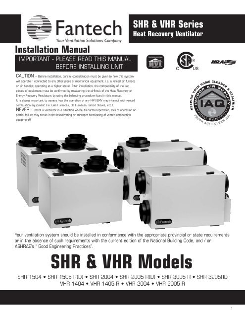
<strong>SHR</strong> & <strong>VHR</strong> Series<br />
Heat Recovery Ventilator<br />
Your ventilation system should be installed in conformance with the appropriate provincial or state requirements<br />
or in the absence of such requirements with the current edition of the National Building Code, and / or<br />
A<strong>SHR</strong>AE’s “ Good Engineering Practices”.<br />
<strong>SHR</strong> & <strong>VHR</strong> <strong>Models</strong><br />
<strong>SHR</strong> 1504 • <strong>SHR</strong> 1505 R(D) • <strong>SHR</strong> 2004 • <strong>SHR</strong> 2005 R(D) • <strong>SHR</strong> 3005 R • <strong>SHR</strong> 3205RD<br />
<strong>VHR</strong> 1404 • <strong>VHR</strong> 1405 R • <strong>VHR</strong> 2004 • <strong>VHR</strong> 2005 R<br />
1
TABLE OF CONTENTS<br />
TECHNICAL DATA<br />
<strong>SHR</strong>(D) Series . . . . . . . . . . . . . . . . . . . . . . . . . . . . . . . . . . . . . . . . . . . . . . . . . . . . . . . . . . . . . . . . . . . . . . .3<br />
<strong>SHR</strong> Series . . . . . . . . . . . . . . . . . . . . . . . . . . . . . . . . . . . . . . . . . . . . . . . . . . . . . . . . . . . . . . . . . . . . . . . . .4<br />
<strong>SHR</strong> 3005R . . . . . . . . . . . . . . . . . . . . . . . . . . . . . . . . . . . . . . . . . . . . . . . . . . . . . . . . . . . . . . . . . . . . . . . . 5<br />
<strong>VHR</strong> Series . . . . . . . . . . . . . . . . . . . . . . . . . . . . . . . . . . . . . . . . . . . . . . . . . . . . . . . . . . . . . . . . . . . . . . . . .7<br />
MODES OF OPERATION . . . . . . . . . . . . . . . . . . . . . . . . . . . . . . . . . . . . . . . . . . . . . . . . . . . . . . . . . . . . . . . . . . . . . . . .<br />
INSTALLATION . . . . . . . . . . . . . . . . . . . . . . . . . . . . . . . . . . . . . . . . . . . . . . . . . . . . . . . . . . . . . . . . . . . . . . . . . . . . . .9<br />
Mounting the Unit . . . . . . . . . . . . . . . . . . . . . . . . . . . . . . . . . . . . . . . . . . . . . . . . . . . . . . . . . . . . . . . . . . . . 9<br />
Location & Ducting . . . . . . . . . . . . . . . . . . . . . . . . . . . . . . . . . . . . . . . . . . . . . . . . . . . . . . . . . . . . . . . . . . . 10<br />
Examples . . . . . . . . . . . . . . . . . . . . . . . . . . . . . . . . . . . . . . . . . . . . . . . . . . . . . . . . . . . . . . . . . . . . . . . . .12<br />
Air Flow Balancing . . . . . . . . . . . . . . . . . . . . . . . . . . . . . . . . . . . . . . . . . . . . . . . . . . . . . . . . . . . . . . . . . . 14<br />
ELECTRICAL CONNECTIONS . . . . . . . . . . . . . . . . . . . . . . . . . . . . . . . . . . . . . . . . . . . . . . . . . . . . . . . . . . . . . . . .... 15<br />
Example for maximum airflow normally required.<br />
HRVs are typically sized to ventilate the whole house at a minimum of 0.35 air changes per<br />
hour. To calculate, simply take the square footage of the house (including basement) and multiply<br />
by the height of the ceiling to get cubic volume. Then, divide by 60 and multiply by 0.35.<br />
Example: SQFT of House 1100<br />
Basement 1100<br />
Total SQFT 2200<br />
Height of ceiling x 8<br />
Cubic volume 17600<br />
/ 60<br />
Maximum airflow required (CFM) 293<br />
x 0.35<br />
103<br />
* Always consult your local code for sizing requirements in your area.<br />
Alternate Method<br />
***Illustrations &<br />
images in this<br />
manual may not be<br />
exactly like unit<br />
purchase, these<br />
illustrations &<br />
images are for<br />
examples only.***<br />
1 cfm = 0.47189 l/s<br />
1 l/s = 3.6 m 3 /hr<br />
Room classification Number of rooms CFM (L/s) CFM Required<br />
Master bedroom x 20 cfm (10 l/s) =<br />
Basement yes or no if yes add 20 cfm / 10 l/s<br />
if no = 0<br />
=<br />
Bedrooms x 10 cfm (5 l/s) =<br />
Living room x 10 cfm (5 l/s) =<br />
Others x 10 cfm (5 l/s) =<br />
Kitchen x 10 cfm (5 l/s) =<br />
Bathroom x 10 cfm (5 l/s) =<br />
Laundry room x 10 cfm (5 l/s) =<br />
Utility room x 10 cfm (5 l/s) =<br />
2<br />
Total Ventilation Requirements (add last column ) =
<strong>SHR</strong> 1505R(D) & 2005R Series HRV<br />
Dimensions<br />
5 TH port for recirculation defrost<br />
type models only<br />
5 TH port for recirculation defrost type models only<br />
E<br />
6"<br />
A B CC C D<br />
Model A B C D E<br />
<strong>SHR</strong> 1505R(D) 2 ¹⁄₄" (56mm) 23 ¹⁄₂" (596mm) 2 ⁵⁄₈" (67mm) 17 ³⁄₈" (441mm) 17 ³⁄₈" (441mm)<br />
<strong>SHR</strong> 2005R(D) 2 ¹⁄₄" (56mm) 27 ⁷⁄₈" (707mm) 2 ⁵⁄₈" (67mm) 17 ³⁄₈" (441mm) 20 ¹⁄₂" (520mm)<br />
Fan Performance<br />
Performance Data<br />
Model<br />
Apparent<br />
Sensible<br />
Effectiveness at<br />
32ºF (0ºC)<br />
Apparent<br />
Sensible<br />
Effectiveness at<br />
-13ºF (-25ºC)<br />
<strong>SHR</strong> 1505R(D) 72 % 69 %<br />
<strong>SHR</strong> 2005R(D) 71 % 76 %<br />
AIRFLOW CAP. cfm (L/s) @ 0.4 on High Speed<br />
Power<br />
• Volts<br />
• Amperage<br />
<strong>SHR</strong> 1505R(D)<br />
<strong>SHR</strong> 2005R(D)<br />
• Phase<br />
120 VAC<br />
1.5 Amps Total<br />
1.9 Amps Total<br />
Single Phase<br />
Airflow<br />
5 TH port for recirculation defrost models<br />
only can be ducted or left open<br />
Fresh Air<br />
From Outside<br />
Stale Air<br />
From Inside<br />
Stale Air<br />
To Outside<br />
Fresh Air<br />
To Inside<br />
3
<strong>SHR</strong> 1504 & 2004 Series HRV<br />
Dimensions<br />
E<br />
6"<br />
A B C D<br />
Model A B C D E<br />
<strong>SHR</strong> 1504 2 ¹⁄₄" (56mm) 23 ¹⁄₂" (596mm) 2 ⁵⁄₈" (67mm) 17 ³⁄₈" (441mm) 16 ¹⁄₈" (413mm)<br />
<strong>SHR</strong> 2004 2 ¹⁄₄" (56mm) 27 ⁷⁄₈" (707mm) 2 ⁵⁄₈" (67mm) 17 ³⁄₈" (441mm) 20 ¹⁄₂" (520mm)<br />
Fan Performance<br />
Performance Data<br />
Model<br />
Apparent<br />
Sensible<br />
Effectiveness at<br />
32ºF (0ºC)<br />
Apparent<br />
Sensible<br />
Effectiveness at<br />
-13ºF (-25ºC)<br />
<strong>SHR</strong> 1504 72 % 69 %<br />
<strong>SHR</strong> 2004 71 % 76 %<br />
AIRFLOW CAP. cfm (L/s) @ 0.4 on High Speed<br />
Power<br />
• Volts<br />
• Amperage<br />
<strong>SHR</strong> 1504<br />
<strong>SHR</strong> 2004<br />
• Phase<br />
120 VAC<br />
1.5 Amps Total<br />
1.9 Amps Total<br />
Single Phase<br />
Airflow<br />
Fresh Air<br />
From Outside<br />
Stale Air<br />
From Inside<br />
Stale Air<br />
To Outside<br />
Fresh Air<br />
To Inside<br />
4
<strong>SHR</strong> 3005R Series HRV<br />
Dimensions<br />
5 TH port for recirculation defrost<br />
type models only<br />
E<br />
6"<br />
A B C D<br />
Model A B C D E<br />
<strong>SHR</strong> 3005R 2 ¹⁄₄" (56mm) 50 ⁷⁄₈" (1292mm) 2 ¹⁄₄" (56mm) 17 ³⁄₈" (441mm) 22 ¹⁄₄" (564mm)<br />
<strong>SHR</strong> 2005R(D) 2 ¹⁄₄" (56mm) 27 ⁷⁄₈" (707mm) 2 ⁵⁄₈" (67mm) 17 ³⁄₈" (441mm) 20 ¹⁄₂" (520mm)<br />
Fan Performance<br />
Performance Data<br />
Model<br />
Apparent<br />
Sensible<br />
Effectiveness at<br />
32ºF (0ºC)<br />
Apparent<br />
Sensible<br />
Effectiveness at<br />
-13ºF (-25ºC)<br />
<strong>SHR</strong> 3005R 92 % 91 %<br />
AIRFLOW CAP. cfm (L/s) @ 0.4 on High Speed<br />
Power<br />
• Volts<br />
• Amperage<br />
• Phase<br />
120 VAC<br />
2.7 Amps Total<br />
Single Phase<br />
Airflow<br />
5 TH port for recirculation defrost models<br />
only, can be ducted or left open<br />
Fresh Air<br />
From Outside<br />
Fresh Air<br />
To Inside<br />
Stale Air<br />
To Outside<br />
Stale Air<br />
From Inside<br />
5
<strong>SHR</strong> 3205RD Series HRV<br />
Dimensions<br />
Access<br />
Door<br />
Access<br />
Door<br />
8"<br />
200mm<br />
E<br />
A B C D<br />
Model A B C D E<br />
<strong>SHR</strong> 3005R 2 ¹⁄₄" (56mm) 27 ⁷⁄₈" (1292mm) 2 ³⁄₄" (71mm) 25 ¹⁄₈" (638mm) 22 ¹⁄₂" (520mm)<br />
<strong>SHR</strong> 2005R(D) 2 ¹⁄₄" (56mm) 27 ⁷⁄₈" (707mm) 2 ⁵⁄₈" (67mm) 17 ³⁄₈" (441mm) 20 ¹⁄₂" (520mm)<br />
Fan Performance<br />
Performance Data<br />
Model<br />
Apparent Sensible<br />
Effectiveness at<br />
32ºF (0ºC)<br />
Apparent Sensible<br />
Effectiveness at<br />
-13ºF (-25ºC)<br />
<strong>SHR</strong>3205RD 72%<br />
77%<br />
AIRFLOW CAP. cfm (L/s) @ 0.4 on High Speed<br />
Power<br />
• Volts<br />
• Amperage<br />
• Phase<br />
120VAC<br />
2.5 Amps<br />
Single Phase<br />
Airflow<br />
Damper<br />
Door<br />
Electrostatic<br />
Filters<br />
Fresh Air<br />
From Outside<br />
Stale Air<br />
From Inside<br />
Stale Air<br />
To Outside<br />
Fresh Air<br />
To Inside<br />
6<br />
EBM Motor Aluminum Core Electrical Box
<strong>VHR</strong> 1404, 1405R, 2004 & 2005R Series HRV<br />
Dimensions<br />
D<br />
C<br />
A<br />
B<br />
Model A B C D<br />
<strong>VHR</strong> 1404 23 ³⁄₄" (604mm) 17 ¹⁄₄" (438mm) 16 ¹⁄₄" (413mm) 2 ¹⁄₄" (56mm)<br />
<strong>VHR</strong> 2004 28" (711mm) 17 ¹⁄₄" (438mm) 20 ¹⁄₂" (521mm) 2 ¹⁄₄" (56mm)<br />
<strong>VHR</strong> 1405R 23 ³⁄₄" (604mm) 17 ¹⁄₄" (438mm) 16 ¹⁄₄" (413mm) 2 ¹⁄₄" (56mm)<br />
<strong>VHR</strong> 2005R 28" (711mm) 17 ¹⁄₄" (438mm) 20 ¹⁄₂" (521mm) 2 ¹⁄₄" (56mm)<br />
Fan Performance<br />
Airflow (L/s)<br />
0.00 19.00 38.00 57.00 76.00 94.00 114.00<br />
1.2<br />
300.00<br />
1<br />
250.00<br />
Performance Data<br />
Model<br />
Apparent Sensible<br />
Effectiveness at<br />
32ºF (0ºC)<br />
Apparent Sensible<br />
Effectiveness at<br />
-13ºF (-25ºC)<br />
Static Pressure (in WC)<br />
0.8<br />
0.6<br />
0.4<br />
0.2<br />
<strong>VHR</strong>1404/<br />
<strong>VHR</strong>1405R<br />
0<br />
0.00 40.00 80.00 120.00 160.00<br />
Airflow (cfm)<br />
<strong>VHR</strong>2004<br />
<strong>VHR</strong>2005R<br />
200.00<br />
150.00<br />
100.00<br />
50.00<br />
0.00<br />
200.00 240.00<br />
Static Pressure (Pa)<br />
<strong>VHR</strong> 1404/1405R 81 % 79 %<br />
<strong>VHR</strong> 2004/2005R 71 % 76 %<br />
<strong>VHR</strong> 1405R 81 % 79 %<br />
<strong>VHR</strong> 2005R 71 % 76 %<br />
AIRFLOW CAP. cfm (L/s) @ 0.4 on High Speed<br />
Power<br />
• Volts<br />
• Amperage<br />
<strong>VHR</strong> 1404/1405R<br />
<strong>VHR</strong> 2004/2005R<br />
• Phase<br />
120VAC<br />
1.4 Amps<br />
1.6 Amps<br />
Single<br />
Airflow<br />
Stale Air<br />
To Outside<br />
Fresh Air<br />
From Outside<br />
Stale Air<br />
From Inside<br />
Fresh Air<br />
To Inside<br />
Optional recirculation<br />
duct collar (provided)<br />
with <strong>VHR</strong> 1405R<br />
& <strong>VHR</strong> 2005R only<br />
* All collars on the<br />
<strong>VHR</strong> Series have a<br />
diameter of 6".<br />
7
MODES OF OPERATION<br />
The entire line of <strong>SHR</strong>(D) / <strong>VHR</strong> / SER / VER series Heat Recovery & Energy Recovery Ventilators comes equipped with Fantech's new electronic<br />
uni-control board which offers a wide variety of features making it the ultimate ventilation control system. Fantech engineers have used the latest<br />
technology to provide solid, trouble free operation under any conditions.<br />
The Fantech uni-control board offers stand alone operating capabilities as well as an exclusive 2 wire communication to most external controls.<br />
The trouble-free optional controls include: two different rotary dial dehumidistats, an air quality sensor (3 wire communication required), a 15<br />
minute remote push-button timer, as well as the most sophisticated line of remote wall mounted controls, the Intellitek EDF5 (5MR).<br />
An on-board diagnostic LED helps find problems quickly and efficiently. For example the LED can be used to signal a broken or shorted electronic<br />
wall control wire. Electronic air temperature probe gives this board accurate readings in order to minimize unnecessary defrost operation, and the<br />
on-board jumpers provide the user with the option of adjusting defrost time and sequence to optimize performance under abnormal conditions. The<br />
defrost operation is automatic and is usually never adjusted.<br />
Air from<br />
Outside<br />
Air to<br />
Outside<br />
Air from<br />
House<br />
Air to<br />
House<br />
1. Continuous / Ventilation<br />
Mode<br />
In this mode of operation<br />
both fans are operating and<br />
exchanging air with the outside.<br />
The heat recovery ventilator<br />
(HRV) constantly exchanges the air at the rate you select,<br />
either at low or medium speed, and switches to high speed when<br />
activated by an optional remote control. The "Low" and "Med" fan<br />
speed selection will cause the unit to operate in continuous exchange<br />
mode at an exchange rate of 35% and 50% maximum airflow rating<br />
respectively. Continuous mode is recommended, since pollutants are<br />
slowly but constantly being generated in your house.<br />
* no exchange of air<br />
2. Intermittent / Standby Mode (<strong>SHR</strong>(D) /<br />
<strong>VHR</strong> / SER / VER Series of HRV / ERV’s)<br />
The system is always on standby and<br />
operates at high speed when activated by<br />
an optional remote control. "Standby"<br />
should be selected if the user wishes to<br />
stop the unit from continuous exchange. We recommend that the<br />
"Standby" mode only be used if your system is equipped with an<br />
optional external control, in which case, the unit would activate to<br />
"High" fan speed, until the control is satisfied and then return to<br />
standby (off).<br />
Air from<br />
House<br />
Air to<br />
House<br />
3.Defrost/Recirculation Mode<br />
(5 port “R” <strong>Models</strong>)<br />
The automatic defrost cycle<br />
<strong>SHR</strong> R(D) / <strong>VHR</strong> R models of<br />
HRV consists of a damper<br />
defrost which allows air to<br />
recirculate throughout the unit & home. When the supply air<br />
stream temperature goes below -5°C (23°F), the exhaust motor<br />
shuts down, the supply motor goes to high speed, and a damper<br />
closes the supply, opening a 5th collar. The ambient air is then<br />
recirculated through the unit & home for a period of 5 minutes.<br />
The unit will then resume normal operation for a time period of 25<br />
minutes. This damper defrost cycle continues until the supply air<br />
stream rises above 0°C (32°F). The recirculation feature can be<br />
obtained with the use of an optional Intellitek EDF5 (5MR) control.<br />
Air to<br />
outside<br />
Air from<br />
House<br />
4. Defrost (Fan shutdown 4<br />
port models)<br />
The automatic defrost cycle<br />
<strong>SHR</strong> / <strong>VHR</strong> / SER / VER models<br />
of HRV / ERV’s consists<br />
of a fan shutdown. When the<br />
supply air stream temperature goes below -5°C (23°F), the supply<br />
motor shuts down and the exhaust motor goes into high<br />
speed. Ambient air is passed through the unit for a period of 5<br />
minutes. The supply motor will then re-start and run at the preset<br />
speed. The exhaust motor will also slow down to the preset<br />
speed, and the unit will operate in the run cycle for 25 minutes.<br />
This fan shutdown defrost cycle continues until the supply air<br />
stream rises above 0°C (32°F).<br />
NOTE: Some products may not be exactly as illustrated in the Installation, Operation and Maintenance Manual.<br />
Fantech Inc. reserves the right to modify, at any time and without notice, any or all of its products’ features, designs, components<br />
and specifications, to maintain their technological leadership position.<br />
8
INSTALLATION<br />
PRACTICAL TIPS<br />
• Install the unit close to<br />
the outside wall on<br />
which the supply and<br />
exhaust hoods will be<br />
mounted.<br />
• Have a nearby power<br />
supply 120 Volts, 60Hz.<br />
• Have the possibility of<br />
mounting the unit to<br />
supporting beams.<br />
LOCATION<br />
The HRV must be located in a heated space where it will be possible to conveniently service the<br />
unit. Typically the HRV would be located in the mechanical room or an area close to the outside<br />
wall where the weatherhoods will be mounted. If a basement area is not convenient or does not<br />
exist, a utility or laundry room may be used.<br />
Attic installations are not normally recommended due to:<br />
- the complexity of work to install<br />
- freezing conditions in the attic<br />
- difficulty of access for service and cleaning<br />
Connecting appliances to the HRV It is not recommended, including:<br />
- clothes dryer<br />
- range top<br />
- stovetop fan<br />
- central vacuum system<br />
These appliance may cause lint, dust or grease to collect in the HRV , damaging the unit.<br />
NOTE: Connecting any of these type of appliances to the HRV will invalidate your warranty<br />
MOUNTING<br />
• Mount the unit as<br />
level as possible in<br />
order to allow proper<br />
condensate drainage.<br />
• Have access to<br />
a water drain for the<br />
condensate of the unit<br />
during defrost.<br />
• Have a certain amount<br />
of heat around the unit<br />
(attic installation is not<br />
recommended).<br />
• Minimize any noise<br />
level that would be<br />
created by the unit in<br />
the living area.<br />
• Have access for future<br />
maintenance.<br />
1 Place Fastening hooks<br />
on the strapping board<br />
or the floor joists.<br />
2 Attach a hanging chain<br />
(provided) to each 10 3/4”<br />
(19 mm) bolt (provided) in<br />
the top 4 corners of the<br />
unit and tighten.<br />
3 Hang the unit by<br />
slipping a link onto the<br />
hanging hooks, making<br />
sure the unit is level.<br />
Installing Drain Line<br />
Through normal operation and during its defrost mode, the HRV may produce some condensation.<br />
This water should flow into a nearby drain, or be taken away by a condensate pump. The HRV and<br />
all condensate lines must be installed in a space where the temperature is maintained above the<br />
freezing point. A “P” trap should be made in the drain line. This will prevent odors from being<br />
drawn back up into the unit.<br />
1 Install the drain nipple.<br />
2 Install the drain hose,<br />
making a “P” trap<br />
9
INSTALLING DUCTS GOING TO / FROM OUTSIDE<br />
PRACTICAL<br />
TIPS<br />
•Decide where your intake and<br />
exhaust hoods will be located.<br />
Locating the Intake<br />
Weatherhood<br />
• Should be located upstream<br />
(if there are prevailing winds)<br />
from the exhaust outlet<br />
• At least 6’ (2m) away from<br />
dryer vents and furnace<br />
exhaust ( medium or high efficiency<br />
furnaces)<br />
• A minimum of at least 6’ (2m)<br />
from driveways, oil fill pipes,<br />
gas meters, or garbage containers<br />
• At least 18” (457mm) above<br />
the ground, or above the<br />
depth of expected snow accumulation<br />
• At least 3’ (1m) from the corner<br />
of the building<br />
• Do not locate in a garage,<br />
attic or crawl space<br />
A well designed and installed ducting system will allow the HRV to operate at its maximum efficiency.<br />
Always try to keep duct runs as short and straight as possible.<br />
See Installation Diagrams for installation examples.<br />
INSTALLING THE DUCTING<br />
TO THE WEATHERHOODS<br />
The inner liner of the flexible insulated duct<br />
must be clamped to the sleeve of the weatherhoods<br />
(as close to the outside as possible)<br />
and to the appropriate port on the HRV. The<br />
insulation should remain full and not be<br />
squished. The outer liner, which acts as a<br />
vapor barrier must be completely sealed to<br />
outer wall and the HRV using tape and or<br />
caulking. A good bead of high quality caulking<br />
(preferably acoustical sealant) will seal<br />
the inner flexible duct to both the HRV port<br />
and the weatherhood prior to clamping.<br />
To minimize air flow restriction, the flexible<br />
insulated duct that connects the two outside<br />
weatherhoods to the HRV should be<br />
stretched tightly and be as short as possible.<br />
Twisting of folding the duct will severely<br />
restrict air flow.<br />
Locating the Exhaust<br />
Weatherhood<br />
• At least 18” (457mm) above<br />
ground or above the depth of<br />
expected snow accumulation<br />
• At least 3’ (1m) away from<br />
the corner of the building<br />
• Not near a gas meter, electric<br />
meter or a walkway where fog<br />
or ice could create a hazard<br />
• Not into a garage, workshop<br />
or other unheated space<br />
When installing the weatherhood,<br />
it’s outside perimeter<br />
must be sealed with exterior<br />
caulking.<br />
1 Using the collar of<br />
the outside hood,<br />
outline the intake &<br />
exhaust holes to be<br />
cut. The holes<br />
should be slightly<br />
larger than the collar<br />
to allow for the<br />
thickness of the<br />
insulated flexible<br />
duct. Cut a hole<br />
for both the intake<br />
and exhaust hoods.<br />
2 Pull the insulated<br />
flexible duct<br />
through the<br />
opening until it is<br />
well extended and<br />
straight. Slide the<br />
duct’s inner vinyl<br />
sleeve over the<br />
hood collar and<br />
secure, pull the<br />
insulation over the<br />
duct and then the<br />
vapor barrier over<br />
the sleeve and<br />
secure with duct<br />
tape.<br />
3 Push the hood into<br />
the opening. Attach<br />
the hood to the<br />
outside wall with<br />
mounting screws.<br />
Repeat the<br />
installation<br />
procedure for both<br />
the Supply and<br />
Exhaust hood.<br />
4 Using a caulking<br />
gun, seal around<br />
both hoods to prevent<br />
any leaks.<br />
10
INSTALLING DUCTS TO / FROM INSIDE<br />
To maximize airflow in the ductwork system, all ducts should be kept short and have as few bends or elbows as possible. Forty-five<br />
degree are preferred to 90º elbows. Use “Y” tees instead of 90º elbows whenever possible.<br />
All duct joints must be fastened with screws or duct sealant and wrapped with a quality duct tape to prevent leakage. Aluminum foil<br />
duct tape is recommended. Galvanized ducting from the HRV/ERV to the living areas in the house is recommended whenever possible,<br />
although flexible duct can be used in moderation when necessary.<br />
SUPPLY AIR DUCTING<br />
In homes without a forced air furnace, fresh air should be supplied to all habitable rooms including, bedrooms and living areas. It<br />
should be supplied from high wall or ceiling locations. Grilles that diffuse the air comfortably such as Fantech grille {MGE (metal) or<br />
PGE (plastic)}s are recommended.To avoid possible noise transfer through the ductwork system, a short length (approximately 12”,<br />
300 mm) of nonmetallic flexible insulated duct should be connected between the HRV/ERV and the supply/exhaust ductwork system.<br />
The main supply and return lines to/from the HRV/ERV must be 6 inches (150 mm) minimum. Branch lines to the individual rooms<br />
may be as small as 4 inches (100 mm), but 5 inch (125 mm) lines are preferred.If the floor is the only option available, then special<br />
care should be taken in locating grilles. Areas such as under baseboard heaters will help to temper the air. Also optional inline duct<br />
heaters are available for mounting in the supply duct work to add heat if required.In homes with a forced air furnace, you may want to<br />
connect the HRV/ERV to the furnace ductwork (see information below).<br />
Exhaust Air Ducting<br />
The stale air exhaust system is used to draw air from the points in the house where the worst air quality problems occur. It is recommended<br />
that return air ducts be installed in the bathroom, kitchen, and laundry room. Additional return air ducts from strategic<br />
locations (i.e. greenhouse, atrium, swimming pool, sauna, etc.) may be installed. The furnace return duct may be also used to<br />
exhaust from. In this method, the exhaust air is not ducted back from bathrooms, kitchens, etc to the HRV/ERV with “dedicated<br />
lines”.<br />
DUCTING FIFTH PORT UNITS (R)<br />
All <strong>SHR</strong>(D) / <strong>VHR</strong> / SER / VER Series R (1405R, 1505R, 2005R & 3005R) HRV / ERV’s have a fifth duct port on top (<strong>SHR</strong>(D)/SER) or<br />
side (<strong>VHR</strong>/VER) of the unit. This duct port is for both defrost and the recirculation mode. A motorized damper installed in the port<br />
closes during defrost or recirculation temporarily blocking the incoming fresh air-stream, allowing the warm air from the house to<br />
circulate through the HRV / ERV. You may wish to duct this port to a common clean air room (living room or dining room) so when<br />
recirculation is activated, household odors from the kitchen, bathroom or basement won’t be introduced into the living spaces of the<br />
home environment.<br />
11
INSTALLATION EXAMPLES<br />
Example diagram only-duct configuration may change depending on model<br />
The recirculation function can be accessed with a optional EDF5 (5MR) intellitek control. It allows air to move gently throughout the<br />
home without exchanging air to the outside, until needed.<br />
Fully Dedicated System<br />
(new construction)<br />
Bedrooms<br />
Fresh Air<br />
1800 mm<br />
HRV<br />
FEL 4 (4” Miter Elbow)<br />
Exhaust CG 4 (4” Adjustable Grill)<br />
Bathroom<br />
Central Control - optional<br />
Exhaust Air<br />
460 mm<br />
Fresh air to living room<br />
Example diagram only-duct configuration may change depending on model<br />
DIRECT CONNECTION of the SUPPLY AIR STREAM to the FURNACE COLD AIR RETURN<br />
(Stale air drawn from key areas of home)<br />
Partially Dedicated System<br />
Bedrooms<br />
FEL 4 (4” Miter Elbow)<br />
Exhaust CG 4 (4” Adjustable Grill)<br />
Central Control - optional<br />
Bathroom<br />
Return Air<br />
Furnace thermostat<br />
NOTES:<br />
1.Furnace blower may be required to operate when HRV/ERV is on to<br />
provide good air distribution.<br />
2.Weatherhood arrangement is for drawing purposes only. 6’ (2m)<br />
minimum separation recommended.<br />
18” (460mm) above grade minimum.<br />
3.Due to the differences in pressure between the HRV/ERV and the<br />
equipment it is being connected to, the HRV/ERV’s airflow must be<br />
confirmed on site, using the balancing procedure found in the installation<br />
manual.<br />
HRV<br />
Connection<br />
1800 mm<br />
HRV<br />
Fresh Air<br />
Exhaust Air<br />
460 mm<br />
12
INSTALLATION EXAMPLES (CONT'D)<br />
Example diagram only-duct configuration may change depending on model<br />
DIRECT CONNECTION of both the HRV/ERV SUPPLY AIR STREAM and<br />
EXHAUST AIR STREAM to the FURNACE COLD AIR RETURN<br />
Simplified Installation<br />
Option 1<br />
(Return/Return Method)<br />
NOTES:<br />
1. Furnace blower must operate when ventilation from HRV/ERV is<br />
required. The furnace should be set to run continuously or interlocked<br />
with HRV/ERV.<br />
2. A minimum separation of 39 inches (1m) is recommended between the<br />
two direct connections.<br />
3. The exhaust air connection should be upstream of the supply air connection<br />
to prevent exhausting any fresh air.<br />
4. Weatherhood arrangement is for drawing purposes only.<br />
5. Due to the differences in pressure between the HRV/ERV and the equipment<br />
it is being connected to, the HR/ERV’s airflow should be confirmed<br />
on site, using the balancing procedure found in the installation manual.<br />
DIRECT CONNECTION of both the HRV/ERV SUPPLY AIR STREAM &<br />
EXHAUST AIR STREAM to the FURNACE COLD AIR RETURN & SUPPLY AIR SIDE<br />
Simplified Installation<br />
Option 2<br />
(Supply/Return Method)<br />
NOTES:<br />
1. Furnace blower may be required to operate when ventilation from<br />
HRV/ERV is required. The furnace should be set to run continuously<br />
or interlocked with HRV/ERV.<br />
2. The exhaust air connection should be upstream of the supply air connection<br />
to prevent exhausting any fresh air.<br />
3. Weatherhood arrangement is for drawing purposes only. Six feet<br />
(2m) minimum separation recommended. Eighteen inches (460 mm)<br />
above grade minimum.<br />
4. Due to the differences in pressure between the HRV/ERV and the<br />
equipment it is being connected to, the HR/ERV’s airflow must be<br />
confirmed on site, using the balancing procedure found in the installation<br />
manual.<br />
13
AIR FLOW BALANCING<br />
AIRFLOW STATION (GRID) METHOD<br />
B<br />
1 For this flow measuring station, cut<br />
the duct and place the flow<br />
measuring station between each<br />
station. Make sure that the flow<br />
measuring station’s air direction<br />
arrow points in the direction of the<br />
airflow. Secure the flow measuring<br />
station with duct tape.<br />
2 Before taking the reading, make sure<br />
that the magnehelic gauge is level<br />
and at 0. Refer to the flow<br />
measuring station’s chart to<br />
determine your unit’s airflow velocity.<br />
3 Adjust the “Supply Air Out” damper<br />
until you reach the desired velocity.<br />
Follow the previous steps to adjust<br />
the “Exhaust Air Out” damper, if<br />
needed.<br />
18”<br />
(457 mm)<br />
Measure<br />
here<br />
18”<br />
(457 mm)<br />
Measure<br />
here<br />
• To avoid airflow<br />
turbulence and incorrect<br />
readings, the airflow<br />
velocity should be<br />
measured on steel<br />
ducting a minimum of<br />
18” (457 mm) from the<br />
unit or elbow and before<br />
any transition.<br />
ADJUSTING AIRFLOWS<br />
ELECTRONIC BALANCING MOTORS<br />
[<strong>SHR</strong> 1505R(D), <strong>SHR</strong> 2005R, <strong>VHR</strong> 1405R & <strong>VHR</strong> 2005R only] -<br />
Motors will be factory set at their full potential depending on speed selected.<br />
When unit is installed you will need to balance the motors for proper operation.<br />
Insert screwdriver and turn clockwise to slow down the motor, you will notice the motor changing speeds<br />
while performing this operation. Set to desired cfm.<br />
Use slot screwdriver to<br />
adjust speed/airflow<br />
-<br />
+<br />
Fan<br />
14 14
ELECTRICAL CONNECTIONS<br />
U<br />
- +<br />
* Wiring diagram of complete unit inside of access panel<br />
Diagnostic<br />
LED<br />
Air Quality<br />
Sensor<br />
3 wires<br />
EDF5 or EDF2 (not shown)<br />
2 wires<br />
EDF<br />
FURNACE<br />
INTERLOCK<br />
+ -<br />
TIMER<br />
+ -<br />
COM<br />
DEHUM<br />
+ -<br />
N.O.<br />
CUR SW<br />
IN COM<br />
N.C.<br />
EDF1<br />
2 wires<br />
Dehumidistat<br />
2 wires<br />
RTS3 (observe plarity)<br />
15-minute timer<br />
(up to 5 timers)<br />
Mechanical<br />
Crank Timer<br />
2 wires<br />
and /<br />
or<br />
and /<br />
or<br />
(1 only)<br />
Dehumidistat<br />
On/Off<br />
4 wires<br />
15<br />
3 position mode<br />
selection switch<br />
Custom defrost<br />
mode jumper<br />
selection<br />
15
ELECTRICAL CONNECTIONS (CONT'D)<br />
WHITE<br />
BLUE<br />
YELLOW<br />
BLACK<br />
TR1 WHITE<br />
J7 J6 J5 J4 J3 J2 J1<br />
BLACK<br />
BROWN<br />
GREY<br />
BROWN<br />
DEFROST<br />
RED<br />
WHITE<br />
BLACK<br />
WHITE<br />
NO<br />
BROWN<br />
BLUE<br />
BLACK<br />
BROWN<br />
BLUE<br />
BLACK<br />
COM<br />
SUP<br />
EXH<br />
PC<br />
SW2<br />
LOW<br />
STAND BY<br />
MED<br />
SW1<br />
RED<br />
T.P<br />
CAP2<br />
GREEN<br />
BLACK<br />
CM T1 T2<br />
AUX<br />
COM<br />
N.O.<br />
N.C.<br />
CAP1<br />
RED<br />
RED<br />
EDF<br />
+<br />
FURNACE<br />
INTERLOCK<br />
DEHUM<br />
+<br />
N.O.<br />
CUR SW<br />
IN<br />
COM<br />
N.C.<br />
-<br />
WHITE<br />
ORANGE<br />
YELLOW<br />
WHT/YELLOW<br />
GREEN<br />
WHT/GREEN<br />
WHT/BLUE<br />
BLUE<br />
+<br />
TIMER<br />
-<br />
COM<br />
-<br />
PWR<br />
N.O.<br />
COM<br />
EXP<br />
PROGRAM<br />
LINE<br />
CUR SW<br />
DEHUM<br />
TIMER<br />
AQS<br />
WALL<br />
16 16<br />
BLACK
17<br />
17
18 18
The Best<br />
Limited Warranty<br />
in the Business<br />
• The heat recovery polypropylene core<br />
has a limited lifetime warranty.<br />
• The motors found in all Fantech<br />
HRV’s & ERV’s require no lubrication,<br />
and are factory balanced to prevent<br />
vibration and promote silent<br />
operation.<br />
• The limited warranty covers normal<br />
use. It does not apply to any defects,<br />
malfunctions or failures as a result of<br />
improper installation, abuse,<br />
mishandling, misapplication,<br />
fortuitous occurrence or any other<br />
circumstances outside Fantech’s<br />
control.<br />
• Inappropriate installation or<br />
maintenance may result in the<br />
cancellation of the warranty.<br />
• Any unauthorized work will result in<br />
the cancellation of the warranty.<br />
• Fantech is not responsible for any<br />
incidental or consequential damages<br />
incurred in the use of the ventilation<br />
system.<br />
• Fantech is not responsible for<br />
providing an authorized service centre<br />
near the purchaser or in the general<br />
area.<br />
• Fantech reserves the right to supply<br />
refurbished parts as replacements.<br />
• Transportation, removal and<br />
installation fees are the responsibility<br />
of the purchaser.<br />
• The purchaser is responsible to<br />
adhering to all codes in effect in his<br />
area.<br />
• The warranty is limited to 5 years on<br />
parts and 7 years on the motor from<br />
the date of purchase, including parts<br />
replaced during this time period. If<br />
there is no proof of purchase<br />
available, the date associated with<br />
the serial number will be used for<br />
the beginning of the warranty period.<br />
* This warranty is the exclusive and<br />
only warranty in effect relative to the<br />
ventilation system and all other<br />
warranties either expressed or<br />
implied are invalid.<br />
19<br />
United States<br />
1712 Northgate Blvd.,<br />
Sarasota, FL. 34234<br />
Phone: 800.747.1762;<br />
941.309.6000<br />
Fax: 800.487.9915; 941.309.6099<br />
www.fantech.net; info@fantech.net<br />
Canada<br />
50 Kanalflakt Way,<br />
Bouctouche, NB E4S 3M5<br />
Phone: 800.565.3548;<br />
506.743.9500<br />
Fax: 877.747.8116; 506.743.9600<br />
www.fantech.ca; info@fantech.ca<br />
Fantech, reserves the right to modify, at any time and without<br />
notice, any or all of its products’ features, designs, components and<br />
specifications to maintain their technological leadership position.<br />
Article #: 301038<br />
Item #: 401347<br />
Rev Date: 010307<br />
19